EP2148105B1 - Monoblock-Fahrradkurbelgarnitur - Google Patents
Monoblock-Fahrradkurbelgarnitur Download PDFInfo
- Publication number
- EP2148105B1 EP2148105B1 EP09305549A EP09305549A EP2148105B1 EP 2148105 B1 EP2148105 B1 EP 2148105B1 EP 09305549 A EP09305549 A EP 09305549A EP 09305549 A EP09305549 A EP 09305549A EP 2148105 B1 EP2148105 B1 EP 2148105B1
- Authority
- EP
- European Patent Office
- Prior art keywords
- crankset
- axis
- cycle
- fact
- piece
- Prior art date
- Legal status (The legal status is an assumption and is not a legal conclusion. Google has not performed a legal analysis and makes no representation as to the accuracy of the status listed.)
- Active
Links
- 239000000463 material Substances 0.000 claims description 15
- 239000002131 composite material Substances 0.000 claims description 12
- 238000005299 abrasion Methods 0.000 claims description 9
- 229910045601 alloy Inorganic materials 0.000 claims description 8
- 239000000956 alloy Substances 0.000 claims description 8
- 238000006116 polymerization reaction Methods 0.000 claims description 3
- 239000000543 intermediate Substances 0.000 description 12
- 229910001234 light alloy Inorganic materials 0.000 description 6
- 235000008612 Gnetum gnemon Nutrition 0.000 description 3
- 240000000018 Gnetum gnemon Species 0.000 description 3
- 238000004519 manufacturing process Methods 0.000 description 3
- 239000002184 metal Substances 0.000 description 2
- 125000006850 spacer group Chemical group 0.000 description 2
- OKTJSMMVPCPJKN-UHFFFAOYSA-N Carbon Chemical compound [C] OKTJSMMVPCPJKN-UHFFFAOYSA-N 0.000 description 1
- 238000004026 adhesive bonding Methods 0.000 description 1
- 229910052799 carbon Inorganic materials 0.000 description 1
- 238000012423 maintenance Methods 0.000 description 1
- 238000010079 rubber tapping Methods 0.000 description 1
Images


Classifications
-
- B—PERFORMING OPERATIONS; TRANSPORTING
- B62—LAND VEHICLES FOR TRAVELLING OTHERWISE THAN ON RAILS
- B62M—RIDER PROPULSION OF WHEELED VEHICLES OR SLEDGES; POWERED PROPULSION OF SLEDGES OR SINGLE-TRACK CYCLES; TRANSMISSIONS SPECIALLY ADAPTED FOR SUCH VEHICLES
- B62M3/00—Construction of cranks operated by hand or foot
- B62M3/003—Combination of crank axles and bearings housed in the bottom bracket
-
- B—PERFORMING OPERATIONS; TRANSPORTING
- B62—LAND VEHICLES FOR TRAVELLING OTHERWISE THAN ON RAILS
- B62K—CYCLES; CYCLE FRAMES; CYCLE STEERING DEVICES; RIDER-OPERATED TERMINAL CONTROLS SPECIALLY ADAPTED FOR CYCLES; CYCLE AXLE SUSPENSIONS; CYCLE SIDE-CARS, FORECARS, OR THE LIKE
- B62K19/00—Cycle frames
- B62K19/30—Frame parts shaped to receive other cycle parts or accessories
- B62K19/34—Bottom brackets
-
- Y—GENERAL TAGGING OF NEW TECHNOLOGICAL DEVELOPMENTS; GENERAL TAGGING OF CROSS-SECTIONAL TECHNOLOGIES SPANNING OVER SEVERAL SECTIONS OF THE IPC; TECHNICAL SUBJECTS COVERED BY FORMER USPC CROSS-REFERENCE ART COLLECTIONS [XRACs] AND DIGESTS
- Y10—TECHNICAL SUBJECTS COVERED BY FORMER USPC
- Y10T—TECHNICAL SUBJECTS COVERED BY FORMER US CLASSIFICATION
- Y10T74/00—Machine element or mechanism
- Y10T74/21—Elements
- Y10T74/2164—Cranks and pedals
Definitions
- the present invention relates to a cycle pedal, and in particular a monobloc pedals, and a cycle provided with such a pedal.
- the cycle cranks include a crank axle, two cranks fixed to the ends of the axle, and a large pinion integral in rotation with the crank axle.
- the cranks extend in opposite directions and comprise at their free end means for fixing a pedal axle.
- These fixing means are generally constituted by a simple tapped hole receiving the threaded end of the pedal shaft.
- crank axle is adapted to be received in a bottom bracket of a cycle frame with the interposition of bearings arranged at the ends of the bottom bracket axle and thus forming a hub allowing the rotation of the bottom bracket axis at the bottom. inside the bottom bracket tube.
- crank axle and the two cranks together form a single piece of metal which generally has the shape of a "Z".
- Such a monobloc cycle crank is known from the patent US4418584 which describes a pedal crank whose crank axle and cranks are manufactured in one piece. This document relates in particular to how to mount the large gear on the cycle pedal for easy replacement if the large pinion is damaged.
- a one-piece cycle crankset according to the preamble of claim 1 is described in the patent US4545691 which shows a similar monobloc pedals in which inner rings of the two bearings are connected to each other by a sleeve.
- the object of the invention is to overcome these disadvantages by proposing a solution allowing the use of a monobloc cycle crankset of a composite material or a light hollow alloy in order to significantly lighten the entire crankset.
- a monobloc cycle crankset of a composite material or a light hollow alloy in order to significantly lighten the entire crankset.
- the new design provides improved rigidity of the whole assembly and allows to use the maximum volume available at the same time that the walls can be made relatively thin to maintain a reduced weight.
- the object of the invention is a one-piece cycle crankset, comprising a first crank connected to a second crank by a crank axle forming with it a piece in one piece, the crank axis being adapted to being accommodated in a pedal tube of a cycle frame with the interposition of a first bearing and a second bearing arranged around the bottom bracket axis near the ends thereof to allow rotation of the crank axle within said bottom bracket tube, a large chain drive sprocket being disposed near one end of the crank axle and rotatably connected therewith, a first and a second intermediate ring made of a material with high rigidity and abrasion resistant being fixed on the bottom bracket axis near a respective end thereof to receive a respective bearing, characterized in that said brackets intermediates are fixed on the bottom bracket axle by polymerization of said composite material of the bottom bracket axle following a expanding said material.
- Another object of the invention is a cycle provided with a pedal as defined above.
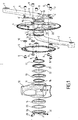
- the figure 1 shows a cycle pedal according to the invention comprising a first crank 1 connected to a second crank 2 by a crank axle 3.
- the cranks 1 and 2 extend in opposite directions from a respective end of the crankset shaft 3.
- the cranks 1 and 2 are capable of carrying at their end a respective pedal (not shown) whose threaded axis can be screwed into a threaded hole 7 at the end of the crank.
- the crankset comprises two large pinions consisting of a first circular toothed plate 4 and a second circular toothed plate 5 fixed to a star-shaped tray holder 6 integral in rotation with the bottom bracket shaft 3.
- the teeth of the first and second plates 4, 5 are able to cooperate with a drive chain (not shown) which in turn rotates the rear wheel (not shown) of a cycle.
- This pedal cycle is thus double trays, that is to say it comprises a first toothed plate 4 which is larger than the second toothed plate 5 for obtaining a large development for the use of the cycle downhill or plain, while the second plate 5, smaller, makes it easier to climb the ribs or start more easily.
- the first and second trays 4, 5 are fixed on the branches 6 'of the tray holder 6 by means of fixing means such as screws 8 which pass through holes provided in the trays and in the tray holder to cooperate with nuts 9, with the interposition of spacers 10 between the first and second plates.
- the bottom bracket shaft 3 is adapted to be housed in a bottom bracket 11 of a cycle frame 12, of which only the part concerned by the invention is shown in the figures.
- a first bearing 13 and a second bearing 14 connect the bottom bracket to the bottom bracket tube being arranged around the bottom bracket axis near the ends thereof. This arrangement will be described in detail later.
- the first and second cranks 1, 2 and the crank axis 3 are made of a composite material. According to another aspect of the invention, the first and second cranks 1, 2 and the crank axis 3 are made of a hollow light alloy, for example formed by hydroforming.
- a first and second intermediate rings 15, 16 made of a high rigidity and abrasion resistant material are fixed on the bottom bracket shaft 3 near a respective end thereof to receive in tight connection a respective bearing 13, 14.
- the high rigidity and abrasion resistant material of the first and second intermediate rings 15, 16 is preferably a light alloy having the characteristics necessary to withstand abrasion.
- the intermediate rings 15, 16 may be fixed to the bottom bracket shaft 3 by gluing or, very advantageously, in the case where the material of the one-piece crankset is a composite material, they may be fixed thereto by the polymerization of the composite material of the pedal axle following an expansion of the material which can for example be obtained by inflation with compressed air.
- the intermediate rings 15, 16 can be fixed on the crankset 3 during the manufacture of the crankset monobloc, and more precisely the rings 15, 16 are during manufacture set up on the bottom bracket to be fixed by the expansion of the alloy during hydroforming.
- the tray holder 6 is part of the integral part formed by the cranks 1, 2 and the bottom bracket 3.
- the branches 6 'of the tray carrier 6 originate directly on the end of the first crank 1 connected to the bottom bracket 3, being centered on the axis AA thereof.
- crankset with the crankset 11 of the frame 12 are illustrated on the figure 1 .
- the first bearing 13 is immobilized on the crank axle 3 by means of two stop rings 17, 18 disposed on either side of the bearing 13 and entering corresponding grooves 19, 20 provided on the axle. of bottom bracket.
- a washer 21 and a seal 22 are placed between the bearing 13 and the stop ring 17 on the side of the tray holder 6. In this way is obtained a subassembly held in place during assembly.
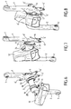
- the second bearing 14 is fixed inside the bottom bracket tube 11 against a first circular abutment rib 23, as illustrated in FIG. figure 3 .
- a second circular abutment rib 24 is provided in the bottom bracket tube 11, against which the first bearing 13 must then be supported.
- a seal 25 is in the assembly placed against the outer face of the second bearing 14 and the whole assembly is held in place by means of an assembly ring 26 which has a tapping 27 fit to cooperate with a thread 28 provided on the second intermediate ring 16, the side of the outer edge thereof.
- the connecting ring 26 is preferably slotted so that its screwing on the threading 28 is facilitated by the introduction of a shim 29 into the slot 30 of the ring which keeps it spaced at the right size and it is then easy to screw the assembly ring 26 onto the thread 28 of the second intermediate ring 16, until a free assembly is obtained without excessive play.
- the figure 5 shows the last phase of this assembly after which the shim 29 is removed after this adjustment, while the figure 4 shows the relative position of the parts assembled on the bottom bracket 3.
- the assembly ring 26 advantageously has a fixing hole 31 extending perpendicularly to the slot 30 of the ring 26 on either side of it to receive a fastening and clamping screw 32.
- the fixing hole 31 is preferably threaded to cooperate directly with the thread of the screw 32.
- the bottom bracket shaft 3 advantageously has a concave central recess 33 so that it does not interfere. assembly of the pedal with the frame. This recess 33 can be combined with a round convex conformation 34 on the nascent part of the second crank 2.
- Figures 6 to 8 illustrate three consecutive phases of the assembly of the crankset according to the invention on a cycle frame.
Landscapes
- Engineering & Computer Science (AREA)
- Mechanical Engineering (AREA)
- Chemical & Material Sciences (AREA)
- Combustion & Propulsion (AREA)
- Transportation (AREA)
- Gears, Cams (AREA)
- Devices For Conveying Motion By Means Of Endless Flexible Members (AREA)
- Shafts, Cranks, Connecting Bars, And Related Bearings (AREA)
- Transmission Devices (AREA)
Claims (12)
- Monoblock-Kettentrieb für Zweirad, der eine erste Kurbel (1) aufweist, die durch eine Kettentrieb-Achse (3) mit einer zweiten Kurbel (2) verbunden ist und mit dieser ein einziges zusammenhängendes Teil bildet, wobei die Kettentrieb-Achse (3) imstande ist, in einem Kettentrieb-Rohr (11) eines Zweiradrahmens (12) platziert zu sein mit Zwischenstellung eines ersten Lagers (13) und eines zweiten Lagers (14), die um die Kettentrieb-Achse (3) in der Nähe der Enden derselben angeordnet sind, um die Rotation der Kettentrieb-Achse im Kettentrieb-Rohr (11) zu erlauben, wobei ein großes Antriebszahnrad (4, 5) einer Kette in der Nähe eines der Enden der Kettentrieb-Achse (3) angeordnet und mit dieser rotierend verbunden ist, wobei ein erster und ein zweiter Zwischenring (15, 16) aus einem abriebfesten Werkstoff mit höherer Festigkeit auf der Kettentrieb-Achse (3) in der Nähe eines jeweiligen Endes derselben befestigt sind, um ein jeweiliges Lager (13, 14) aufzunehmen, dadurch gekennzeichnet, dass der Werkstoff des Kettentriebs ein Verbundwerkstoff ist und dass die Zwischenringe (15, 16) auf der Kettentrieb-Achse (3) durch Polymerisation des Verbundwerkstoffs der Kettentrieb-Achse nach einer Expansion des Werkstoffs befestigt sind.
- Monoblock-Kettentrieb für Zweirad nach Anspruch 1, dadurch gekennzeichnet, dass der Werkstoff des Kettentriebs eine ausgehöhlte Leichtmetall-Legierung ist.
- Monoblock-Kettentrieb für Zweirad nach Anspruch 2, dadurch gekennzeichnet, dass die Zwischenringe (15, 16) auf der Kettentrieb-Achse (3) durch Expansion der Legierung bei Formung des Kettentrieb befestigt werden.
- Monoblock-Kettentrieb für Zweirad nach einem der vorangehenden Ansprüche, dadurch gekennzeichnet, dass der vom großen Zahnrad (4, 5) am weitesten entfernte Zwischenring (16) auf seinem nach außen gerichteten Ende mit einem Gewinde (28) ausgestattet ist, das imstande ist, mit einem Verbindungsring (26) mit Gewinde zusammenzuarbeiten.
- Monoblock-Kettentrieb für Zweirad nach Anspruch 4, dadurch gekennzeichnet, dass der Verbindungsring (26) geschlitzt ist, um in seinem Schlitz (30) einen Einlagekeil (29) aufnehmen zu können, der bei der Montage die Verschraubung des Verbindungsrings (26) auf dem Gewinde (28) des Zwischenrings (16) erleichtert.
- Monoblock-Kettentrieb für Zweirad nach Anspruch 5, dadurch gekennzeichnet, dass der Verbindungsring (26) ein Befestigungsloch (31) aufweist, das sich senkrecht zum Schlitz (30) des Verbindungsrings (26) auf der einen und anderen Seite desselben erstreckt, um eine Befestigungs- und Feststellschraube (32) aufnehmen zu können.
- Monoblock-Kettentrieb für Zweirad nach einem der vorangehenden Ansprüche, dadurch gekennzeichnet, dass die Kettentrieb-Achse (3) eine konkave zentrale Aussparung (33) aufweist, die die Montage des Kettentriebs mit dem Rahmen erleichtert.
- Monoblock-Kettentrieb für Zweirad nach einem der vorangehenden Ansprüche, wobei das große Zahnrad (4, 5) aus einer kreisförmigen gezahnten Platte besteht, die von einem Plattenhalter (6) getragen wird, dadurch gekennzeichnet, dass der Plattenhalter (6) Bestandteil des zusammenhängenden Teils (1, 2, 3) ist.
- Monoblock-Kettentrieb für Zweirad nach Anspruch 8, dadurch gekennzeichnet, dass der Plattenhalter (6) die Form eines Sterns hat, dessen Strahlen (6') direkt auf dem Ende der ersten Kurbel (1) ihren Anfang nehmen, die mit der Kettentrieb-Achse (3) verbunden ist, wobei sie auf der Achse (A-A) derselben zentriert sind.
- Monoblock-Kettentrieb für Zweirad nach einem der vorangehenden Ansprüche, dadurch gekennzeichnet, dass das erste Lager (13) auf der Kettentrieb-Achse (3) mit Hilfe von zwei Feststellringen (17, 18) festgestellt ist, die auf der einen und der anderen Seite des Lagers (13) angeordnet sind und in entsprechende Aushöhlungen (19, 20) eingreifen, die auf der Kettentrieb-Achse (3) vorgesehen sind.
- Monoblock-Kettentrieb für Zweirad nach einem der vorangehenden Ansprüche, dadurch gekennzeichnet, dass der abriebfeste Werkstoff mit höherer Festigkeit des ersten und zweiten Zwischenrings (15, 16) eine Leichtmetall-Legierung ist.
- Zweirad mit Monoblock-Kettentrieb für Zweirad, dadurch gekennzeichnet, dass der Kettentrieb die Merkmale eines der Anspruche 1 bis 11 aufweist.
Applications Claiming Priority (1)
| Application Number | Priority Date | Filing Date | Title |
|---|---|---|---|
| FR0804195A FR2934239B1 (fr) | 2008-07-23 | 2008-07-23 | Pedalier de cycle monobloc |
Publications (2)
| Publication Number | Publication Date |
|---|---|
| EP2148105A1 EP2148105A1 (de) | 2010-01-27 |
| EP2148105B1 true EP2148105B1 (de) | 2012-12-26 |
Family
ID=40138385
Family Applications (1)
| Application Number | Title | Priority Date | Filing Date |
|---|---|---|---|
| EP09305549A Active EP2148105B1 (de) | 2008-07-23 | 2009-06-16 | Monoblock-Fahrradkurbelgarnitur |
Country Status (5)
| Country | Link |
|---|---|
| US (1) | US20100018345A1 (de) |
| EP (1) | EP2148105B1 (de) |
| CN (1) | CN101633389B (de) |
| FR (1) | FR2934239B1 (de) |
| TW (1) | TW201012705A (de) |
Families Citing this family (3)
| Publication number | Priority date | Publication date | Assignee | Title |
|---|---|---|---|---|
| TW201223823A (en) * | 2011-10-07 | 2012-06-16 | li-he Yao | Torque sensing device for power assisting bicycle |
| CN104828201A (zh) * | 2015-05-19 | 2015-08-12 | 天津市兴轮生产力促进有限公司 | 一体成型自行车牙盘 |
| CN109722381A (zh) * | 2019-03-05 | 2019-05-07 | 南华大学 | 用于微生物培养与生长监测的装置及方法 |
Family Cites Families (29)
| Publication number | Priority date | Publication date | Assignee | Title |
|---|---|---|---|---|
| US529110A (en) * | 1894-11-13 | Crank-shaft and bearing for velocipedes | ||
| US552376A (en) * | 1895-12-31 | William h | ||
| US604710A (en) * | 1898-05-24 | James r | ||
| US1449235A (en) * | 1921-06-08 | 1923-03-20 | Mead Cycle Company | Crank-hanger assembly |
| US3551004A (en) * | 1968-11-19 | 1970-12-29 | American Mach & Foundry | Bicycle improvement |
| JPS5943189Y2 (ja) | 1980-06-11 | 1984-12-20 | 株式会社シマノ | 自転車用ギヤクランク装置 |
| US4552468A (en) * | 1982-02-17 | 1985-11-12 | Hopper Jr Willard C | Bicycle sealed bearing kit |
| US4545691A (en) * | 1983-07-18 | 1985-10-08 | B. Linn Kastan | Bicycle crank bearing assembly |
| US4602524A (en) * | 1984-11-19 | 1986-07-29 | General Signal Corporation | Method of manufacturing bicycle chain drives |
| US4704919A (en) * | 1984-11-28 | 1987-11-10 | Durham Roger O | Two-piece crankshaft for bicycles |
| CN2052744U (zh) * | 1989-08-23 | 1990-02-14 | 于金祥 | 自行车高速比传动装置 |
| US6116114A (en) * | 1993-08-23 | 2000-09-12 | Edwards; Craig H. | Rotatable spindle assembly utilizing two-piece spindle |
| US5493937A (en) * | 1993-08-23 | 1996-02-27 | Edwards; Craig H. | Light-weight bicycle crankshaft assembly utilizing two-piece axle integrally joined to crank arms |
| JP3149374B2 (ja) | 1996-12-27 | 2001-03-26 | 株式会社シマノ | 自転車用中空クランクとその製造方法 |
| US6443033B1 (en) * | 1997-04-11 | 2002-09-03 | Timothy Eugene Brummer | Two-piece bicycle crankset |
| US5941135A (en) * | 1997-06-18 | 1999-08-24 | Schlanger; Raphael | Bicycle crankshaft assembly |
| US6829965B1 (en) * | 1999-05-28 | 2004-12-14 | Bruno Mombrinie | Two-piece bicycle crank set |
| US6164157A (en) * | 1999-07-14 | 2000-12-26 | Chen; Hsing-Lung | Bicycle crankset |
| US6264226B1 (en) * | 2000-02-07 | 2001-07-24 | Chu-Chan Chang | Pedal crank structure of children's bike |
| ITTO20010617A1 (it) * | 2001-06-27 | 2002-12-27 | Campagnolo Srl | Pedivella per bicicletta e procedimento per la sua fabbricazione. |
| CN2559552Y (zh) * | 2001-09-12 | 2003-07-09 | 王新疆 | 自行车链条传动机构 |
| EP1486412B1 (de) * | 2003-06-10 | 2014-05-07 | Campagnolo S.R.L. | Fahrradtretkurbel |
| JP2006046501A (ja) * | 2004-08-04 | 2006-02-16 | Yamamoto Seisakusho:Kk | 軸受構造 |
| US7784378B2 (en) * | 2004-11-17 | 2010-08-31 | Raphael Schlanger | Bicycle crank assembly |
| DE102005022808A1 (de) * | 2005-05-12 | 2006-11-16 | Frank Weidner | Sicherungseinrichtung für Steuerkopflagerungen und Verfahren zur Sicherung von Steuerkopflagerungen |
| EP1749736A1 (de) * | 2005-08-03 | 2007-02-07 | Campagnolo S.R.L. | Fahrradkomponente aus Verbundwerkstoff mit Einsätzen und deren Herstellung |
| US20070295157A1 (en) * | 2006-06-27 | 2007-12-27 | Specialized Bicycle Components, Inc. | Crankset assembly for a bicycle |
| US7650818B2 (en) * | 2007-03-30 | 2010-01-26 | Shimano Inc. | Bicycle shaft component |
| US20090056496A1 (en) * | 2007-09-04 | 2009-03-05 | Dodman Christopher P | Composite Crank Assembly |
-
2008
- 2008-07-23 FR FR0804195A patent/FR2934239B1/fr not_active Expired - Fee Related
-
2009
- 2009-06-16 EP EP09305549A patent/EP2148105B1/de active Active
- 2009-07-20 US US12/505,559 patent/US20100018345A1/en not_active Abandoned
- 2009-07-21 TW TW098124510A patent/TW201012705A/zh unknown
- 2009-07-23 CN CN2009101604737A patent/CN101633389B/zh active Active
Also Published As
| Publication number | Publication date |
|---|---|
| EP2148105A1 (de) | 2010-01-27 |
| FR2934239B1 (fr) | 2010-08-20 |
| FR2934239A1 (fr) | 2010-01-29 |
| CN101633389B (zh) | 2013-01-02 |
| TW201012705A (en) | 2010-04-01 |
| US20100018345A1 (en) | 2010-01-28 |
| CN101633389A (zh) | 2010-01-27 |
Similar Documents
| Publication | Publication Date | Title |
|---|---|---|
| EP0270388B1 (de) | Kurbel für Tretlager eines Fahrrads | |
| EP1780113B1 (de) | Automatische Fahrradpedale mit bügelförmiger Schuhplattenbefestigung | |
| FR2614596A1 (fr) | Pedale de bicyclette | |
| EP1741943B2 (de) | Lageranordnung zur Kraftübertragung einer Windenergieanlage | |
| FR2893303A1 (fr) | Pedalier de cycle | |
| WO1999029564A1 (fr) | Pedalier sans point mort, et ensemble comprenant un tel pedalier et un appareil de mesure | |
| EP3908512A1 (de) | Elektrische unterstützungsvorrichtung für ein fahrrad | |
| EP2148105B1 (de) | Monoblock-Fahrradkurbelgarnitur | |
| EP3908511A2 (de) | Untersetzungsgetriebe | |
| FR2629958A1 (fr) | Rotor pour machine electrique excitee par aimants permanents | |
| CH257924A (fr) | Moyeu pour roue arrière de cycles. | |
| FR2855099A1 (fr) | Moyeu central d'une roue de velo et roue equipee d'un tel moyeu | |
| FR2910866A1 (fr) | Dispositif support pour mecanisme d'essuie-glace et procede de fabrication d'un tel dispositif support | |
| FR2707559A1 (fr) | Perfectionnement pour roue destinée à équiper les cycles. | |
| EP0403714B1 (de) | Kraftfahrzeugantrieb mit elektrischen Bremsvorrichtungen | |
| EP2879943B1 (de) | In ein steckenpferd umwandelbares fahrrad | |
| EP4008929B1 (de) | Planetenbaugruppe, planetensatz mit einer solchen baugruppe und getriebe | |
| FR2843364A1 (fr) | Pedalier pour cycle avec un bras de levier optimise | |
| FR2887934A1 (fr) | Palier a bagues retenues radialement | |
| WO2004108514A1 (fr) | Dispositif de fixation d’une roue de velo sur un cadre | |
| FR2649049A1 (fr) | Perfectionnements aux transmissions de vehicules equipees de ralentisseurs electriques | |
| EP2186990B1 (de) | Antrieb für aufrollbaren Verdunkelungsvorhang | |
| FR3054521A1 (fr) | Cycle equipe d'un module d'assistance electrique, et module d'assistance electrique pour un tel cycle | |
| WO2019192789A1 (fr) | Boite de transmission mécanique pour équipement de motoculture, et procédé d'assemblage correspondant. | |
| FR3140303A1 (fr) | roue de véhicule renforcée |
Legal Events
| Date | Code | Title | Description |
|---|---|---|---|
| PUAI | Public reference made under article 153(3) epc to a published international application that has entered the european phase |
Free format text: ORIGINAL CODE: 0009012 |
|
| AK | Designated contracting states |
Kind code of ref document: A1 Designated state(s): AT BE BG CH CY CZ DE DK EE ES FI FR GB GR HR HU IE IS IT LI LT LU LV MC MK MT NL NO PL PT RO SE SI SK TR |
|
| AX | Request for extension of the european patent |
Extension state: AL BA RS |
|
| 17P | Request for examination filed |
Effective date: 20100615 |
|
| 17Q | First examination report despatched |
Effective date: 20111220 |
|
| GRAP | Despatch of communication of intention to grant a patent |
Free format text: ORIGINAL CODE: EPIDOSNIGR1 |
|
| GRAS | Grant fee paid |
Free format text: ORIGINAL CODE: EPIDOSNIGR3 |
|
| GRAA | (expected) grant |
Free format text: ORIGINAL CODE: 0009210 |
|
| AK | Designated contracting states |
Kind code of ref document: B1 Designated state(s): AT BE BG CH CY CZ DE DK EE ES FI FR GB GR HR HU IE IS IT LI LT LU LV MC MK MT NL NO PL PT RO SE SI SK TR |
|
| REG | Reference to a national code |
Ref country code: GB Ref legal event code: FG4D Free format text: NOT ENGLISH |
|
| REG | Reference to a national code |
Ref country code: CH Ref legal event code: EP |
|
| REG | Reference to a national code |
Ref country code: AT Ref legal event code: REF Ref document number: 590650 Country of ref document: AT Kind code of ref document: T Effective date: 20130115 |
|
| REG | Reference to a national code |
Ref country code: DE Ref legal event code: R096 Ref document number: 602009012211 Country of ref document: DE Effective date: 20130307 |
|
| PG25 | Lapsed in a contracting state [announced via postgrant information from national office to epo] |
Ref country code: LT Free format text: LAPSE BECAUSE OF FAILURE TO SUBMIT A TRANSLATION OF THE DESCRIPTION OR TO PAY THE FEE WITHIN THE PRESCRIBED TIME-LIMIT Effective date: 20121226 Ref country code: SE Free format text: LAPSE BECAUSE OF FAILURE TO SUBMIT A TRANSLATION OF THE DESCRIPTION OR TO PAY THE FEE WITHIN THE PRESCRIBED TIME-LIMIT Effective date: 20121226 Ref country code: HR Free format text: LAPSE BECAUSE OF FAILURE TO SUBMIT A TRANSLATION OF THE DESCRIPTION OR TO PAY THE FEE WITHIN THE PRESCRIBED TIME-LIMIT Effective date: 20121226 Ref country code: FI Free format text: LAPSE BECAUSE OF FAILURE TO SUBMIT A TRANSLATION OF THE DESCRIPTION OR TO PAY THE FEE WITHIN THE PRESCRIBED TIME-LIMIT Effective date: 20121226 Ref country code: NO Free format text: LAPSE BECAUSE OF FAILURE TO SUBMIT A TRANSLATION OF THE DESCRIPTION OR TO PAY THE FEE WITHIN THE PRESCRIBED TIME-LIMIT Effective date: 20130326 |
|
| REG | Reference to a national code |
Ref country code: NL Ref legal event code: T3 |
|
| REG | Reference to a national code |
Ref country code: AT Ref legal event code: MK05 Ref document number: 590650 Country of ref document: AT Kind code of ref document: T Effective date: 20121226 |
|
| REG | Reference to a national code |
Ref country code: LT Ref legal event code: MG4D |
|
| PG25 | Lapsed in a contracting state [announced via postgrant information from national office to epo] |
Ref country code: GR Free format text: LAPSE BECAUSE OF FAILURE TO SUBMIT A TRANSLATION OF THE DESCRIPTION OR TO PAY THE FEE WITHIN THE PRESCRIBED TIME-LIMIT Effective date: 20130327 Ref country code: SI Free format text: LAPSE BECAUSE OF FAILURE TO SUBMIT A TRANSLATION OF THE DESCRIPTION OR TO PAY THE FEE WITHIN THE PRESCRIBED TIME-LIMIT Effective date: 20121226 Ref country code: LV Free format text: LAPSE BECAUSE OF FAILURE TO SUBMIT A TRANSLATION OF THE DESCRIPTION OR TO PAY THE FEE WITHIN THE PRESCRIBED TIME-LIMIT Effective date: 20121226 |
|
| PG25 | Lapsed in a contracting state [announced via postgrant information from national office to epo] |
Ref country code: CZ Free format text: LAPSE BECAUSE OF FAILURE TO SUBMIT A TRANSLATION OF THE DESCRIPTION OR TO PAY THE FEE WITHIN THE PRESCRIBED TIME-LIMIT Effective date: 20121226 Ref country code: ES Free format text: LAPSE BECAUSE OF FAILURE TO SUBMIT A TRANSLATION OF THE DESCRIPTION OR TO PAY THE FEE WITHIN THE PRESCRIBED TIME-LIMIT Effective date: 20130406 Ref country code: SK Free format text: LAPSE BECAUSE OF FAILURE TO SUBMIT A TRANSLATION OF THE DESCRIPTION OR TO PAY THE FEE WITHIN THE PRESCRIBED TIME-LIMIT Effective date: 20121226 Ref country code: BG Free format text: LAPSE BECAUSE OF FAILURE TO SUBMIT A TRANSLATION OF THE DESCRIPTION OR TO PAY THE FEE WITHIN THE PRESCRIBED TIME-LIMIT Effective date: 20130326 Ref country code: EE Free format text: LAPSE BECAUSE OF FAILURE TO SUBMIT A TRANSLATION OF THE DESCRIPTION OR TO PAY THE FEE WITHIN THE PRESCRIBED TIME-LIMIT Effective date: 20121226 Ref country code: IS Free format text: LAPSE BECAUSE OF FAILURE TO SUBMIT A TRANSLATION OF THE DESCRIPTION OR TO PAY THE FEE WITHIN THE PRESCRIBED TIME-LIMIT Effective date: 20130426 Ref country code: AT Free format text: LAPSE BECAUSE OF FAILURE TO SUBMIT A TRANSLATION OF THE DESCRIPTION OR TO PAY THE FEE WITHIN THE PRESCRIBED TIME-LIMIT Effective date: 20121226 |
|
| PG25 | Lapsed in a contracting state [announced via postgrant information from national office to epo] |
Ref country code: PT Free format text: LAPSE BECAUSE OF FAILURE TO SUBMIT A TRANSLATION OF THE DESCRIPTION OR TO PAY THE FEE WITHIN THE PRESCRIBED TIME-LIMIT Effective date: 20130426 Ref country code: RO Free format text: LAPSE BECAUSE OF FAILURE TO SUBMIT A TRANSLATION OF THE DESCRIPTION OR TO PAY THE FEE WITHIN THE PRESCRIBED TIME-LIMIT Effective date: 20121226 Ref country code: PL Free format text: LAPSE BECAUSE OF FAILURE TO SUBMIT A TRANSLATION OF THE DESCRIPTION OR TO PAY THE FEE WITHIN THE PRESCRIBED TIME-LIMIT Effective date: 20121226 |
|
| PG25 | Lapsed in a contracting state [announced via postgrant information from national office to epo] |
Ref country code: DK Free format text: LAPSE BECAUSE OF FAILURE TO SUBMIT A TRANSLATION OF THE DESCRIPTION OR TO PAY THE FEE WITHIN THE PRESCRIBED TIME-LIMIT Effective date: 20121226 |
|
| PLBE | No opposition filed within time limit |
Free format text: ORIGINAL CODE: 0009261 |
|
| STAA | Information on the status of an ep patent application or granted ep patent |
Free format text: STATUS: NO OPPOSITION FILED WITHIN TIME LIMIT |
|
| PG25 | Lapsed in a contracting state [announced via postgrant information from national office to epo] |
Ref country code: CY Free format text: LAPSE BECAUSE OF FAILURE TO SUBMIT A TRANSLATION OF THE DESCRIPTION OR TO PAY THE FEE WITHIN THE PRESCRIBED TIME-LIMIT Effective date: 20121226 |
|
| 26N | No opposition filed |
Effective date: 20130927 |
|
| PG25 | Lapsed in a contracting state [announced via postgrant information from national office to epo] |
Ref country code: IT Free format text: LAPSE BECAUSE OF FAILURE TO SUBMIT A TRANSLATION OF THE DESCRIPTION OR TO PAY THE FEE WITHIN THE PRESCRIBED TIME-LIMIT Effective date: 20121226 |
|
| REG | Reference to a national code |
Ref country code: DE Ref legal event code: R097 Ref document number: 602009012211 Country of ref document: DE Effective date: 20130927 |
|
| PG25 | Lapsed in a contracting state [announced via postgrant information from national office to epo] |
Ref country code: MC Free format text: LAPSE BECAUSE OF FAILURE TO SUBMIT A TRANSLATION OF THE DESCRIPTION OR TO PAY THE FEE WITHIN THE PRESCRIBED TIME-LIMIT Effective date: 20121226 |
|
| REG | Reference to a national code |
Ref country code: CH Ref legal event code: PL |
|
| GBPC | Gb: european patent ceased through non-payment of renewal fee |
Effective date: 20130616 |
|
| REG | Reference to a national code |
Ref country code: IE Ref legal event code: MM4A |
|
| PG25 | Lapsed in a contracting state [announced via postgrant information from national office to epo] |
Ref country code: GB Free format text: LAPSE BECAUSE OF NON-PAYMENT OF DUE FEES Effective date: 20130616 Ref country code: IE Free format text: LAPSE BECAUSE OF NON-PAYMENT OF DUE FEES Effective date: 20130616 Ref country code: CH Free format text: LAPSE BECAUSE OF NON-PAYMENT OF DUE FEES Effective date: 20130630 Ref country code: LI Free format text: LAPSE BECAUSE OF NON-PAYMENT OF DUE FEES Effective date: 20130630 |
|
| PG25 | Lapsed in a contracting state [announced via postgrant information from national office to epo] |
Ref country code: MT Free format text: LAPSE BECAUSE OF FAILURE TO SUBMIT A TRANSLATION OF THE DESCRIPTION OR TO PAY THE FEE WITHIN THE PRESCRIBED TIME-LIMIT Effective date: 20121226 |
|
| REG | Reference to a national code |
Ref country code: DE Ref legal event code: R082 Ref document number: 602009012211 Country of ref document: DE Representative=s name: LIPPERT STACHOW PATENTANWAELTE RECHTSANWAELTE , DE Ref country code: DE Ref legal event code: R082 Ref document number: 602009012211 Country of ref document: DE Representative=s name: PATENTANWAELTE LIPPERT, STACHOW & PARTNER, DE |
|
| PG25 | Lapsed in a contracting state [announced via postgrant information from national office to epo] |
Ref country code: TR Free format text: LAPSE BECAUSE OF FAILURE TO SUBMIT A TRANSLATION OF THE DESCRIPTION OR TO PAY THE FEE WITHIN THE PRESCRIBED TIME-LIMIT Effective date: 20121226 |
|
| PG25 | Lapsed in a contracting state [announced via postgrant information from national office to epo] |
Ref country code: HU Free format text: LAPSE BECAUSE OF FAILURE TO SUBMIT A TRANSLATION OF THE DESCRIPTION OR TO PAY THE FEE WITHIN THE PRESCRIBED TIME-LIMIT; INVALID AB INITIO Effective date: 20090616 Ref country code: MK Free format text: LAPSE BECAUSE OF FAILURE TO SUBMIT A TRANSLATION OF THE DESCRIPTION OR TO PAY THE FEE WITHIN THE PRESCRIBED TIME-LIMIT Effective date: 20121226 Ref country code: LU Free format text: LAPSE BECAUSE OF NON-PAYMENT OF DUE FEES Effective date: 20130616 |
|
| REG | Reference to a national code |
Ref country code: FR Ref legal event code: PLFP Year of fee payment: 8 |
|
| REG | Reference to a national code |
Ref country code: FR Ref legal event code: PLFP Year of fee payment: 9 |
|
| REG | Reference to a national code |
Ref country code: FR Ref legal event code: PLFP Year of fee payment: 10 |
|
| PGFP | Annual fee paid to national office [announced via postgrant information from national office to epo] |
Ref country code: NL Payment date: 20220620 Year of fee payment: 14 |
|
| PGFP | Annual fee paid to national office [announced via postgrant information from national office to epo] |
Ref country code: FR Payment date: 20230627 Year of fee payment: 15 Ref country code: DE Payment date: 20230620 Year of fee payment: 15 |
|
| PGFP | Annual fee paid to national office [announced via postgrant information from national office to epo] |
Ref country code: BE Payment date: 20230620 Year of fee payment: 15 |
|
| REG | Reference to a national code |
Ref country code: NL Ref legal event code: MM Effective date: 20230701 |
|
| PG25 | Lapsed in a contracting state [announced via postgrant information from national office to epo] |
Ref country code: NL Free format text: LAPSE BECAUSE OF NON-PAYMENT OF DUE FEES Effective date: 20230701 |