EP0229958A1 - Speed-reducing gear - Google Patents
Speed-reducing gear Download PDFInfo
- Publication number
- EP0229958A1 EP0229958A1 EP86116967A EP86116967A EP0229958A1 EP 0229958 A1 EP0229958 A1 EP 0229958A1 EP 86116967 A EP86116967 A EP 86116967A EP 86116967 A EP86116967 A EP 86116967A EP 0229958 A1 EP0229958 A1 EP 0229958A1
- Authority
- EP
- European Patent Office
- Prior art keywords
- crown
- reducer according
- reducer
- planet gears
- pinion
- Prior art date
- Legal status (The legal status is an assumption and is not a legal conclusion. Google has not performed a legal analysis and makes no representation as to the accuracy of the status listed.)
- Ceased
Links
Images

Classifications
-
- F—MECHANICAL ENGINEERING; LIGHTING; HEATING; WEAPONS; BLASTING
- F16—ENGINEERING ELEMENTS AND UNITS; GENERAL MEASURES FOR PRODUCING AND MAINTAINING EFFECTIVE FUNCTIONING OF MACHINES OR INSTALLATIONS; THERMAL INSULATION IN GENERAL
- F16H—GEARING
- F16H1/00—Toothed gearings for conveying rotary motion
- F16H1/28—Toothed gearings for conveying rotary motion with gears having orbital motion
- F16H1/2809—Toothed gearings for conveying rotary motion with gears having orbital motion with means for equalising the distribution of load on the planet-wheels
- F16H1/2836—Toothed gearings for conveying rotary motion with gears having orbital motion with means for equalising the distribution of load on the planet-wheels by allowing limited movement of the planets relative to the planet carrier or by using free floating planets
-
- B—PERFORMING OPERATIONS; TRANSPORTING
- B25—HAND TOOLS; PORTABLE POWER-DRIVEN TOOLS; MANIPULATORS
- B25J—MANIPULATORS; CHAMBERS PROVIDED WITH MANIPULATION DEVICES
- B25J9/00—Programme-controlled manipulators
- B25J9/10—Programme-controlled manipulators characterised by positioning means for manipulator elements
- B25J9/102—Gears specially adapted therefor, e.g. reduction gears
- B25J9/103—Gears specially adapted therefor, e.g. reduction gears with backlash-preventing means
-
- F—MECHANICAL ENGINEERING; LIGHTING; HEATING; WEAPONS; BLASTING
- F16—ENGINEERING ELEMENTS AND UNITS; GENERAL MEASURES FOR PRODUCING AND MAINTAINING EFFECTIVE FUNCTIONING OF MACHINES OR INSTALLATIONS; THERMAL INSULATION IN GENERAL
- F16H—GEARING
- F16H1/00—Toothed gearings for conveying rotary motion
- F16H1/28—Toothed gearings for conveying rotary motion with gears having orbital motion
- F16H1/2809—Toothed gearings for conveying rotary motion with gears having orbital motion with means for equalising the distribution of load on the planet-wheels
-
- F—MECHANICAL ENGINEERING; LIGHTING; HEATING; WEAPONS; BLASTING
- F16—ENGINEERING ELEMENTS AND UNITS; GENERAL MEASURES FOR PRODUCING AND MAINTAINING EFFECTIVE FUNCTIONING OF MACHINES OR INSTALLATIONS; THERMAL INSULATION IN GENERAL
- F16H—GEARING
- F16H57/00—General details of gearing
- F16H57/08—General details of gearing of gearings with members having orbital motion
- F16H57/082—Planet carriers
Definitions
- each satellite pinion includes a flexible blade of rather complex shape, brazed or welded in its middle in a slot that has the axis of this pinion and at its ends in grooves of a hub which has an internal diameter slightly greater than the diameter of this axis around which it is placed and on which is sintered the inner ring of a needle bearing whose outer ring is toothed.
- the blade is arranged perpendicular to the straight line which joins the center of the axis of the pinion to that of the shaft which carries the sun gear. Furthermore, to prevent the blade from being subjected to unnecessary stresses and to ensure the best possible torsional rigidity to the gearbox, the pinion axis has two diametrically opposite tenons located in a direction perpendicular to the blade which slide in two corresponding grooves in the hub.
- Such a reduction gear has the advantage of being compact and of presenting not only practically zero play and very good torsional rigidity but also a very low primary inertia. In addition, it can be easily adjusted simply by changing the part of which the crown is a part.
- each satellite pinion is carried by a blade, one end of which is rigidly linked to the plate and which is elastically deformable in the direction which allows the crown to press it radially against the drive pinion, while being rigid in the other directions.
- the invention also aims to provide a reducer in which these means are simplified and this object is achieved by providing only to hold the crown of metal tongues which have one of their ends rigidly connected to it and the other secured to a fixed part of the reducer, for example its casing if it has one.
- the reduction gear speed comprises an essentially cylindrical casing 1 with a bottom 2 provided with a central opening 3 by which it is fixed by means of suitable means not shown, for example screws, at the front of a motor 4.
- the shaft 5 of this motor which thus penetrates inside the casing and which also constitutes, in this case, the input shaft of the reduction gear carries at its end a pinion of small diameter 6 with which mesh two identical satellite pinions 7 and 8, arranged substantially symmetrically with respect to its axis of rotation.
- each of these planet gears 7 and 8 is simply formed by a pin 9, respectively 10, which constitutes its axis, by a ball bearing 11, respectively 12, driven on this pin and an outer ring 13, respectively 14, which carries the toothing and which is for example hooped on that not shown of the bearing.
- the casing 1 has a flange 15 which allows a cover 16, also provided with a flange 17, to be held by screws 18.
- This cover 16 which, for a reason which will appear later, has in its middle an internal cylindrical boss 19 is pierced with a central hole 20 in which passes an output shaft 21 which can rotate by means of bearings 22 and 23 located at the two ends of this hole around an axis practically coincident with that of the shaft 5 of the motor 4 and which carries at its end a circular plate 24 centered on this axis.
- this plate 24 in turn carries two blades 25 and 26 substantially parallel to each other at the free ends of which are fixed respectively the axes of the planet gears 7 and 8 and which are elastic in the direction which makes it possible to radially press these pinions on the driving pinion 6 or move them aside, which is symbolized by the double arrows F and F 'in FIG. 2.
- these blades 25 and 26 are flexible in the direction perpendicular to their plane which is itself perpendicular to the plate.
- they are designed so as not to flex laterally, nor to twist, let alone stretch or compress, at least under the effect of the constraints that they may be brought to undergo in the reducer when it operates normally.
- each of the blades 25 and 26 has a relatively thin main part in the form of fork 27, respectively 28, of approximately constant width, with two branches 29, 30 respectively, substantially parallel.
- the blade thickens and widens to form a base 31, respectively 32, by which it is linked to the plate at a location located at the edge thereof.
- the branches 29, 30 are extended by openings 33, respectively 34, which are perpendicular to them and which have holes 35, respectively 36, in which are simply driven the ends of the axis of the satellite pinion.
- the reducer of Figures 1 and 2 also includes, of course, an internally and radially deformable ring gear 39, preferably of steel, with which also mesh the two planet gears 7 and 8 and which plays opposite vis these the same role as the crown of the known reducer which we have spoken, that is to say that it pushes them permanently against the drive pinion 6 and this thanks to the flexibility of the blades 25 and 26.
- an internally and radially deformable ring gear 39 preferably of steel, with which also mesh the two planet gears 7 and 8 and which plays opposite vis these the same role as the crown of the known reducer which we have spoken, that is to say that it pushes them permanently against the drive pinion 6 and this thanks to the flexibility of the blades 25 and 26.
- the diameter of the circle circumscribed to the pinions is for example about 40 mm
- the original diameter of the teeth of the crown may be 0.5 mm less than this. Looking also at the perspective view of FIG.
- this crown is immobilized in rotation only by two tongues 40 and 41 which are connected to it by one of their ends at two diametrically opposite points and whose the other ends are integral with a rigid ring 42 pierced with holes 43 and taken between the casing 1 and the cover 16, the whole that is to say the crown, the tongues and the ring being advantageously made in one piece .
- this shaft 21 has two shoulders which abut laterally against the bearings 22 and 23 in order to prevent it from moving axially in the direction which goes from the inside to the outside of the casing. In the other direction, this axial movement must be avoided by providing external means, not shown, on the output shaft, for example a removable output ring or pinion.
- the reduction gear shown in the drawing also includes means to ensure that the crown continues to mesh correctly with the planet gears in the event of a heavy load, means which are constituted by an internal boss 44 of the casing which surrounds this crown, leaving only a slight clearance between it and it.
- blades which carry the planet gears they could very well not have a main part of both constant width and thickness. They could also not be planar but curved but it would be desirable then that they are thick and that they have a local thinning in order to remain rigid in the desired directions.
Abstract
Description
La présente invention concerne les réducteurs de vitesse et, plus précisément, les réducteurs à trains épicycloïdaux dans lesquels un même pignon planétaire, couplé à un arbre d'entrée, entraîne plusieurs pignons satellites répartis autour de lui et couplés à un arbre de sortie.The present invention relates to speed reducers and, more precisely, planetary gear reducers in which the same planetary gear, coupled to an input shaft, drives several planet gears distributed around it and coupled to an output shaft.
Un réducteur de vitesse perfectionné de ce genre a fait l'objet de la demande de brevet français publiée sous le numéro 2 382 626.An improved speed reducer of this kind was the subject of the French patent application published under the
Tel qu'il est décrit dans cette demande, le réducteur comprend trois pignons satellites dont les axes sont solidaires d'un plateau auquel est fixé l'arbre de sortie et qui engrènent, d'une part, avec un planétaire de petit diamètre porté par l'arbre d'entrée et, d'autre part, avec la denture intérieure d'une couronne radialement déformable qui les entoure et qui est disposée concentriquement par rapport à l'arbre d'entrée.As described in this application, the reduction unit comprises three planet gears whose axes are integral with a plate to which the output shaft is fixed and which mesh, on the one hand, with a planetary gear of small diameter carried by the input shaft and, on the other hand, with the internal toothing of a radially deformable crown which surrounds them and which is arranged concentrically with respect to the input shaft.
Cette couronne, dont la denture a un diamètre primitif inférieur au diamètre du cercle circonscrit aux cercles primitifs des pignons satellites lorsque ceux-ci sont en prise avec le planétaire et en appui sur lui, est prolongée d'un côté par une partie cylindrique mince qui la relie à une autre partie cylindrique qui, elle, est relativement massive et fixée au couvercle du carter. Grâce à cette partie mince, suffisamment longue la couronne peut, tout en étant immobile en rotation, se déformer radialement sans être gênée par sa fixation. De plus, pour éviter qu'elle s'épanouisse du côté opposé à cette fixation quand les pignons satellites la déforment, elle est prolongée, de ce côté aussi, par une partie cylindrique mince, sensiblement de même longueur que l'autre, qui aboutit à une partie coudée à angle droit simulant la partie massive de fixation pour rendre l'ensemble symétrique.This crown, the teeth of which have a pitch diameter smaller than the diameter of the circle circumscribed by the pitch circles of the satellite pinions when the latter are engaged with the planet wheel and resting on it, is extended on one side by a thin cylindrical part which connects it to another cylindrical part which is relatively massive and fixed to the housing cover. Thanks to this thin, sufficiently long part, the crown can, while being stationary in rotation, deform radially without being hindered by its fixing. In addition, to prevent it from flourishing on the side opposite to this fixing when the planet gears deform it, it is extended, on this side also, by a thin cylindrical part, substantially the same length as the other, which ends to a bent part at a right angle simulating the massive fixing part to make the whole symmetrical.
Dans ce réducteur, la couronne doit normalement permettre, grâce à la possibilité qu'elle a de se déformer, de supprimer tout jeu dans le train épicycloïdal formé par les pignons mais pour cela il faut qu'elle puisse presser les pignons satellites sur le pignon d'attaque. Pour cette raison chaque pignon satellite comprend une lame flexible de forme assez complexe, brasée ou soudée en son milieu dans une fente que présente l'axe de ce pignon et à ses extrémités dans des rainures d'un moyeu qui a un diamètre interne légèrement supérieur au diamètre de cet axe autour duquel il est placé et sur lequel est frittée la bague interne d'un roulement à aiguilles dont la bague externe est dentée. Naturellement, pour permettre à la couronne de jouer son rôle, la lame est disposée perpendiculairement à la droite qui joint le centre de l'axe du pignon à celui de l'arbre qui porte le planétaire. Par ailleurs, pour éviter que la lame soit soumise à des contraintes inutiles et assurer la meilleure rigidité torsionnelle possible au réducteur, l'axe du pignon présente deux tenons diamétralement opposés et situés dans une direction perpendiculaire à la lame qui coulissent dans deux rainures correspondantes du moyeu.In this reducer, the crown should normally allow, thanks to the possibility that it has to deform, to eliminate any play in the planetary gear formed by the pinions but for this it must be able to press the satellite pinions on the pinion attack. For this reason each satellite pinion includes a flexible blade of rather complex shape, brazed or welded in its middle in a slot that has the axis of this pinion and at its ends in grooves of a hub which has an internal diameter slightly greater than the diameter of this axis around which it is placed and on which is sintered the inner ring of a needle bearing whose outer ring is toothed. Naturally, to allow the crown to play its role, the blade is arranged perpendicular to the straight line which joins the center of the axis of the pinion to that of the shaft which carries the sun gear. Furthermore, to prevent the blade from being subjected to unnecessary stresses and to ensure the best possible torsional rigidity to the gearbox, the pinion axis has two diametrically opposite tenons located in a direction perpendicular to the blade which slide in two corresponding grooves in the hub.
Enfin, pour empêcher la couronne de se dilater lorsque le réducteur est soumis à des charges élevées on prévoit autour de celle-ci un anneau très rigide monté flottant mais avec un débattement axial limité, en laissant un jeu radial aussi faible que possible entre les deux. On envisage également dans la demande de brevet en question de remplacer cet anneau par un bossage à l'intérieur du carter.Finally, to prevent the crown from expanding when the gear unit is subjected to high loads, a very rigid ring is provided around it, floating but with limited axial clearance, leaving as little radial clearance as possible between the two. . It is also envisaged in the patent application in question to replace this ring with a boss inside the casing.
Un tel réducteur a l'avantage d'être compact et de présenter non seulement un jeu pratiquement nul et une très bonne rigidité torsionnelle mais aussi une inertie primaire très faible. De plus, il peut être facilement réglé simplement en changeant la pièce dont fait partie la couronne.Such a reduction gear has the advantage of being compact and of presenting not only practically zero play and very good torsional rigidity but also a very low primary inertia. In addition, it can be easily adjusted simply by changing the part of which the crown is a part.
Le problème est qu'il se prête mal à une miniaturisation qui permettrait de l'utiliser avantageusement dans des machines, par exemple des robots, de petites dimensions et ceci essentiellement a cause de la structure particulère et relativement complexe de ses pignons satellites. Il n'est pratiquement pas possible en effet de réaliser des pignons de ce genre de petite taille sans que leur prix de revient devienne excessif.The problem is that it does not lend itself well to miniaturization which would allow it to be advantageously used in machines, for example robots, of small dimensions and this essentially because of the particular and relatively complex structure of its satellite pinions. It is practically not possible in fact to produce pinions of this kind of small size without their cost becoming excessive.
L'invention a avant tout pour but de supprimer cet inconvénient et ce but est atteint grâce au fait que dans un réducteur conforme à l'invention, qui comprend lui aussi un plateau couplé à son arbre de sortie, sur lequel sont montés les pignons satellites, et une couronne radialement déformable, dentée intérieurement et immobilisée en rotation, placée autour de ceux-ci, chaque pignon satellite est porté par une lame dont une extrémité est liée rigidement au plateau et qui est déformable élastiquement dans la direction qui permet à la couronne de le presser radialement contre le pignon d'attaque, tout en étant rigide dans les autres directions.The object of the invention is above all to eliminate this drawback and this object is achieved thanks to the fact that in a reduction gear according to the invention, which also includes a plate coupled to its output shaft, on which the planet gears are mounted. , and an radially deformable crown, internally toothed and immobilized in rotation, placed around them, each satellite pinion is carried by a blade, one end of which is rigidly linked to the plate and which is elastically deformable in the direction which allows the crown to press it radially against the drive pinion, while being rigid in the other directions.
Comme on le verra par la suite, il est possible grâce à cela d'utiliser comme pignons satellites des pignons simples que l'on trouve à bas prix dans le commerce et qui peuvent avoir des dimensions réduites.As will be seen later, it is possible thanks to this to use as satellite pinions simple pinions which are found at low cost in the trade and which can have reduced dimensions.
De plus, il est possible de s'arranger pour que ces pignons puissent être changés facilement et rapidement, ce qui n'est pas le cas dans le réducteur connu dont on a parlé.In addition, it is possible to arrange so that these pinions can be changed easily and quickly, which is not the case in the known reducer of which we have spoken.
D'autre part, dans ce réducteur connu, il n'y a pas que les pignons satellites qui sont compliqués. Il y a aussi les moyens par lesquels la couronne est immobilisée en rotation.On the other hand, in this known reducer, it is not only the planet gears which are complicated. There are also the means by which the crown is immobilized in rotation.
L'invention a également pour but de fournir un réducteur dans lequel ces moyens sont simplifiés et ce but est atteint en prévoyant seulement pour tenir la couronne des languettes métalliques qui ont une de leurs extrémités liée rigidement à elle et l'autre solidaire d'une partie fixe du réducteur, par exemple son carter si il en a un.The invention also aims to provide a reducer in which these means are simplified and this object is achieved by providing only to hold the crown of metal tongues which have one of their ends rigidly connected to it and the other secured to a fixed part of the reducer, for example its casing if it has one.
D'autres caractéristiques et avantages du réducteur selon l'invention apparaîtront à la lecture de la description qui suit d'un mode préféré d'exécution, description qui se réfère au dessin annexé sur lequel:
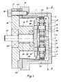
- - la figure 1 est une vue en coupe axiale de ce mode d'exécution, suivant le plan I-I de la figure 2;
- - la figure 2 est une vue en coupe radiale suivant le plan II-II de la figure 1;
- - la figure 3 est une vue en coupe axiale partielle de l'ensemble formé par l'arbre de sortie, le plateau et les lames qui portent les pignons satellites, suivant le plan III-III représenté sur la figure 2; et
- - la figure 4 est une vue en perspective de l'ensemble constitué par la couronne et les moyens qui la tiennent.
- - Figure 1 is an axial sectional view of this embodiment, along the plane II of Figure 2;
- - Figure 2 is a radial sectional view along the plane II-II of Figure 1;
- - Figure 3 is a partial axial sectional view of the assembly formed by the output shaft, the plate and the blades which carry the planet gears, along the plane III-III shown in Figure 2; and
- - Figure 4 is a perspective view of the assembly constituted by the crown and the means which hold it.
Tel qu'il est représenté aux figures 1 et 2, le réducteur de vitesse selon l'invention comprend un carter essentiellement cylindrique 1 avec un fond 2 muni d'une ouverture centrale 3 par lequel il est fixé grâce à des moyens adéquats non représentés, par exemple des vis, à l'avant d'un moteur 4. L'arbre 5 de ce moteur qui pénètre ainsi à l'intérieur du carter et qui constitue aussi, dans ce cas, l'arbre d'entrée du réducteur porte à son extrémité un pignon de petit diamètre 6 avec lequel engrènent deux pignons satellites identiques 7 et 8, disposés sensiblement symétriquement par rapport à son axe de rotation.As shown in Figures 1 and 2, the reduction gear speed according to the invention comprises an essentially cylindrical casing 1 with a
Comme on peut le voir sur la figure 1, chacun de ces pignons satellites 7 et-8 est simplement formé d'une goupille 9, respectivement 10, qui constitue son axe, d'un roulement à billes 11, respectivement 12, chassé sur cette goupille et d'une bague externe 13, respectivement 14, qui porte la denture et qui est par exemple frettée sur celle non représentée du roulement.As can be seen in FIG. 1, each of these
Par ailleurs, du côté opposé à son fond, le carter 1 présente une bride 15 qui permet à un couvercle 16 muni lui aussi d'une bride 17, d'être tenu par des vis 18.Furthermore, on the side opposite its bottom, the casing 1 has a
Ce couvercle 16 qui, pour une raison qui apparaîtra par la suite, présente en son milieu un bossage cylindrique interne 19 est percé d'un trou central 20 dans lequel passe un arbre de sortie 21 qui peut tourner grâce à des paliers 22 et 23 situés aux deux bouts de ce trou autour d'un axe pratiquement confondu avec celui de l'arbre 5 du moteur 4 et qui porte à son extrémité un plateau circulaire 24 centré sur cet axe.This
Conformément à ce qui a été dit précédemment, ce plateau 24 porte à son tour deux lames 25 et 26 sensiblement parallèles entre elles aux extrémités libres desquelles sont fixés respectivement les axes des pignons satellites 7 et 8 et qui sont élastiques dans la direction qui permet de presser radialement ces pignons sur le pignon d'attaque 6 ou de les en écarter, ce qui est symbolisé par les doubles flèches F et F' de la figure 2.In accordance with what has been said previously, this
En d'autres termes ces lames 25 et 26 sont flexibles dans la direction perpendiculaire à leur plan qui est lui-même perpendiculaire au plateau. Par contre, elles sont conçues pour ne pas fléchir latéralement, ni se tordre, ni à fortiori s'étirer ou se comprimer, tout au moins sous l'effet des contraintes qu'elles peuvent être amenées à subir dans le réducteur lorsque celui-ci fonctionne normalement.In other words, these
Avant de parler plus en détail de leur forme il faut encore préciser que dans le mode d'exécution que l'on est en train de décrire elles ne constituent en fait qu'une seule pièce, par exemple en acier ou en aluminium, avec le plateau 24 et l'arbre de sortie 21. Toutefois, il est bien clair que l'on pourrait prévoir de les usiner séparément et de les fixer ensuite sur le plateau par vissage ou soudage. Il en est de même d'ailleurs en ce qui concerne l'arbre 21.Before speaking in more detail about their shape, it should also be pointed out that in the embodiment that we are describing they in fact constitute only one piece, for example of steel or aluminum, with the
Comme le montrent surtout la figure 2 et la figure 3 qui est une vue en coupe partielle de la pièce en question suivant le plan III-III représenté sur cette figure 2, chacune des lames 25 et 26 présente une partie principale relativement mince en forme de fourche 27, respectivement 28, de largeur à peu près constante, avec deux branches 29, respectivement 30, sensiblement parallèles. D'un côté la lame s'épaissit et s'élargit pour former une embase 31, respectivement 32, par laquelle elle est liée au plateau en un endroit situé au bord de celui-ci. De l'autre côté, les branches 29, 30 se prolongent par des épanouissements 33, respectivement 34, qui leur sont perpendiculaires et qui présentent des trous 35, respectivement 36, dans lesquels sont simplement chassés les extrémités de l'axe du pignon satellite.As shown mainly in Figure 2 and Figure 3 which is a partial sectional view of the part in question along the plane III-III shown in this Figure 2, each of the
On peut donc changer facilement les pignons lorsque c'est nécessaire. De plus, rien n'empêche de prévoir dans le plateau des trous en regard de leurs axes comme ceux, 37 et 38, qui sont représentés sur la figure 1 pour faciliter encore plus leur démontage et leur remontage.We can therefore easily change the pinions when necessary. In addition, nothing prevents the provision of holes in the plate opposite their axes such as those, 37 and 38, which are shown in Figure 1 to further facilitate their disassembly and reassembly.
D'autre part, le réducteur des figures 1 et 2 comporte aussi, bien entendu, une couronne dentée intérieurement et radialement déformable 39, de préférence en acier, avec laquelle engrènent également les deux pignons satellites 7 et 8 et qui joue vis-à-vis de ceux-ci le même rôle que la couronne du réducteur connu dont on a parlé, c'est-à-dire qu'elle les pousse en permanence contre le pignon d'attaque 6 et ceci grâce à la flexibilité des lames 25 et 26. Si le diamètre du cercle circonscrit aux pignons est par exemple de 40 mm environ, le diamètre primitif de la denture de la couronne peut être inférieur de 0,5 mm à celui-ci. En regardant également la vue en perspective cavalière de la figure 4, on constate qu'ici cette couronne n'est immobilisée en rotation que par deux languettes 40 et 41 qui sont liées à elle par une de leurs extrémités en deux points diamétralement opposés et dont les autres extrémités sont solidaires d'une bague rigide 42 percée de trous 43 et prise entre le carter 1 et le couvercle 16, le tout c'est-à-dire la couronne, les languettes et la bague étant réalisé avantageusement en une seule pièce.On the other hand, the reducer of Figures 1 and 2 also includes, of course, an internally and radially
Naturellement, les languettes 40 et 41 ont non seulement une minceur mais aussi une longueur suffisantes pour ne pas s'opposer à la déformation radiale de la couronne.Naturally, the
Ceci explique la présence du bossage interne 19 du couvercle du carter car si les languettes ont besoin d'être assez longues pour être très flexibles dans la direction perpendiculaire à leur plan, il y a tout intérêt aussi, pour le bon fonctionnement du réducteur, à ce que le premier palier 22 dans lequel passe l'arbre de sortie 21 soit près du plateau 24.This explains the presence of the
A ce propos il est utile de préciser que cet arbre 21 présente deux épaulements qui viennent buter latéralement contre les paliers 22 et 23 afin de l'empêcher de se déplacer axialement dans le sens qui va de l'intérieur à l'extérieur du carter. Dans l'autre sens ce mouvement axial doit être évité en prévoyant sur l'arbre de sortie des moyens externes non représentés, par exemple une bague ou un pignon de sortie amovible.In this regard, it is useful to specify that this
Enfin, comme celui qui a fait l'objet de la demande de brevet français précitée, le réducteur représenté sur le dessin comprend également des moyens pour faire en sorte que la couronne continue à engrener correctement avec les pignons satellites en cas de charge importante, moyens qui sont constitués par un bossage interne 44 du carter qui entoure cette couronne en ne laissant qu'un faible jeu entre lui et elle.Finally, like the one which was the subject of the aforementioned French patent application, the reduction gear shown in the drawing also includes means to ensure that the crown continues to mesh correctly with the planet gears in the event of a heavy load, means which are constituted by an
Il est bien clair que l'invention n'est pas limitée au mode d'exécution qui vient d'être décrit et que l'on pourrait en imaginer beaucoup d'autres sans sortir du cadre de celle-ci.It is quite clear that the invention is not limited to the embodiment which has just been described and that one could imagine many others without departing from the scope thereof.
Par exemple, on pourrait remplacer le bossage interne dont il vient d'être question par un anneau rigide flottant comme celui que l'on trouve dans la demande de brevet français.For example, we could replace the internal boss just mentioned by a rigid floating ring like the one found in the French patent application.
On pourrait également prévoir plus de deux languettes pour tenir la couronne sans forcément les placer toutes d'un même côté de celle-ci.One could also provide more than two tabs to hold the crown without necessarily placing them all on the same side thereof.
Ces languettes pourraient présenter une ou plusieurs parties amincies pour augmenter leur flexibilité.These tabs could have one or more thinned parts to increase their flexibility.
Leurs extrémités situées du côté opposé à celui de la couronne pourraient être liées au carter, non pas par l'intermédiaire d'une bague, mais directement et pas nécessairement en étant prises entre le carter et son couvercle.Their ends situated on the side opposite that of the crown could be linked to the casing, not by means of a ring, but directly and not necessarily by being caught between the casing and its cover.
Il serait possible aussi de fixer ces languettes de façon à laisser à la couronne la liberté de se déplacer légèrement dans la direction axiale, ce qui lui permettrait de se placer automatiquement dans la meilleure position au cas où il y aurait des défauts dans le train épicycloïdal.It would also be possible to fix these tabs so as to allow the crown the freedom to move slightly in the axial direction, which would allow it to automatically place itself in the best position in case there are defects in the planetary gear .
En ce qui concerne les lames qui portent les pignons satellites, elles pourraient très bien ne pas avoir une partie principale à la fois de largeur et d'épaisseur constantes. Elles pourraient également ne pas être planes mais cintrées mais il serait souhaitable alors qu'elles soient épaisses et qu'elles présentent un amincissement local afin de rester rigides dans les directions voulues.As for the blades which carry the planet gears, they could very well not have a main part of both constant width and thickness. They could also not be planar but curved but it would be desirable then that they are thick and that they have a local thinning in order to remain rigid in the desired directions.
Il y aurait aussi la possibilité de réaliser les pignons satellites différemment, par exemple en remplaçant les roulements à billes par des roulements à aiguilles, et celle de fixer leurs axes au bout des lames non pas simplement en les chassant dans des trous mais, par exemple, en utilisant des bagues de fixation ou en les soudant.There would also be the possibility of making the planet gears differently, for example by replacing the ball bearings by needle bearings, and that of fixing their axes at the end of the blades not simply by driving them into holes but, for example , by using fixing rings or by welding them.
Par ailleurs, on pourrait en prévoir plus de deux mais sans chercher à aller au-delà de trois ou quatre car il est bien évident qu'à partir d'un certain moment il ne serait plus possible d'augmenter le nombre de ces pignons sans réduire leur diamètre et, par conséquent, le rapport de réduction du train épicycloidal. De plus, même en admettant que l'on accepte d'avoir un rapport faible, il y a deux autres raisons qui font que l'on n'a pas intérêt à trop augmenter ce nombre. Tout d'abord, plus il y a de pignons satellites, plus la couronne a de la peine à se déformer et plus la charge supportée par ces derniers et par le pignon d'attaque est importante, même lorsque le couple d'entrée est nul. Ensuite, plus il y a de pignons, plus il faut de lames pour les porter et plus le plateau auquel elles sont liées doit être grand, ce qui peut avoir pour effet d'augmenter l'encombrement du réducteur.Furthermore, we could provide more than two but without trying to go beyond three or four because it is obvious that from a certain moment it would no longer be possible to increase the number of these gables without reduce their diameter and, consequently, the reduction ratio of the planetary gear. In addition, even assuming that we accept to have a weak ratio, there are two other reasons which make it worthless to increase this number too much. First of all, the more satellite pinions, the more the crown has trouble deforming and the more the load supported by the latter and by the drive pinion is high, even when the input torque is zero. Then, the more pinions there are, the more blades are needed to carry them and the larger the plate to which they are linked must be, which can have the effect of increasing the size of the reducer.
Enfin, qu'il s'agisse ou non du mode de réalisation qui a été décrit, il y a toujours la possiblité de monter en série deux réducteurs selon l'invention ou plus dans un même carter.Finally, whether or not this is the embodiment which has been described, there is always the possibility of mounting two or more reduction gears according to the invention in series in the same casing.
Claims (17)
caractérisé par le fait que chaque pignon satellite (7, 8) est porté par une lame (25, 26) dont une extrémité (31, 32) est liée rigidement au plateau (24) et qui est déformable élastiquement dans la direction qui permet à la couronne (39) de presser ledit pignon satellite contre le pignon planétaire (6) et rigide dans les autres directions.1. Speed reducer including:
characterized in that each satellite pinion (7, 8) is carried by a blade (25, 26), one end (31, 32) of which is rigidly connected to the plate (24) and which is elastically deformable in the direction which allows the crown (39) pressing said satellite pinion against the planetary pinion (6) and rigid in the other directions.
Applications Claiming Priority (2)
| Application Number | Priority Date | Filing Date | Title |
|---|---|---|---|
| FR8519229A FR2592122B1 (en) | 1985-12-23 | 1985-12-23 | SPEED REDUCER |
| FR8519229 | 1985-12-23 |
Publications (1)
| Publication Number | Publication Date |
|---|---|
| EP0229958A1 true EP0229958A1 (en) | 1987-07-29 |
Family
ID=9326197
Family Applications (1)
| Application Number | Title | Priority Date | Filing Date |
|---|---|---|---|
| EP86116967A Ceased EP0229958A1 (en) | 1985-12-23 | 1986-12-06 | Speed-reducing gear |
Country Status (2)
| Country | Link |
|---|---|
| EP (1) | EP0229958A1 (en) |
| FR (1) | FR2592122B1 (en) |
Cited By (9)
| Publication number | Priority date | Publication date | Assignee | Title |
|---|---|---|---|---|
| WO2001049553A1 (en) * | 2000-01-05 | 2001-07-12 | Robert Bosch Gmbh | Actuator for an automotive steering device |
| WO2001092759A1 (en) * | 2000-05-27 | 2001-12-06 | Alpha Getriebebau Gmbh | Planetary gear with little play |
| WO2002083479A1 (en) * | 2001-04-14 | 2002-10-24 | Zf Lenksysteme Gmbh | Actuating device for a vehicle steering system |
| US7104918B2 (en) | 2003-07-29 | 2006-09-12 | Pratt & Whitney Canada Corp. | Compact epicyclic gear carrier |
| CN110345233A (en) * | 2019-07-26 | 2019-10-18 | 江苏摩多利传动机械制造有限公司 | A kind of planetary reducer with deformation gear ring structure |
| US10662879B2 (en) | 2017-08-08 | 2020-05-26 | Pratt & Whitney Canada Corp. | Epicyclic gear stage |
| US10760677B2 (en) | 2018-01-31 | 2020-09-01 | Pratt & Whitney Canada Corp. | Epicyclic gear train with balanced carrier stiffness |
| US10927944B2 (en) | 2018-01-26 | 2021-02-23 | Pratt & Whitney Canada Corp. | Compact, twist controlled planet carrier and epicyclic gear train having same |
| DE102021120463A1 (en) | 2021-08-06 | 2023-02-09 | Schaeffler Technologies AG & Co. KG | Planetary gear and roll stabilizer with such a planetary gear |
Families Citing this family (3)
| Publication number | Priority date | Publication date | Assignee | Title |
|---|---|---|---|---|
| FR2651185B1 (en) * | 1989-08-31 | 1991-10-25 | Cousin Freres Sa | REDUCING MECHANISM FOR JOINT WITHOUT GAME USABLE IN PARTICULAR FOR THE ADJUSTMENT OF VARIOUS PARTS OF A MOTOR VEHICLE SEAT. |
| KR100851578B1 (en) * | 2000-08-29 | 2008-08-12 | 가부시키카이샤 나브코 | A driving unit that comprizes a hydraulic motor and a reduction gear |
| DE102013208660A1 (en) * | 2013-05-10 | 2014-11-13 | Schwäbische Hüttenwerke Automotive GmbH | Drive for a compressor to increase the boost pressure of an internal combustion engine |
Citations (7)
| Publication number | Priority date | Publication date | Assignee | Title |
|---|---|---|---|---|
| US2666344A (en) * | 1950-08-14 | 1954-01-19 | Gunther A Boeck | Gear system |
| US2971407A (en) * | 1959-11-09 | 1961-02-14 | Gen Motors Corp | Precision gear train for servo control mechanism |
| US3143899A (en) * | 1962-01-16 | 1964-08-11 | South African Council For Seci | Speed reducer unit or drive |
| US3257869A (en) * | 1963-09-20 | 1966-06-28 | Pennsalt Chemicals Corp | Planetary gearing |
| US3314310A (en) * | 1964-10-08 | 1967-04-18 | United Aircraft Corp | Planet gear construction |
| FR2382626A1 (en) * | 1977-03-03 | 1978-09-29 | Renault | PERFECTED SPEED REDUCER |
| FR2447491A1 (en) * | 1979-01-23 | 1980-08-22 | Renault | Epicyclic gear train with high ratio speed reduction - has elastically deformable toothed ring to eliminate backlash |
Family Cites Families (1)
| Publication number | Priority date | Publication date | Assignee | Title |
|---|---|---|---|---|
| US3142899A (en) * | 1960-10-12 | 1964-08-04 | Edward S Meyer | Extractor |
-
1985
- 1985-12-23 FR FR8519229A patent/FR2592122B1/en not_active Expired
-
1986
- 1986-12-06 EP EP86116967A patent/EP0229958A1/en not_active Ceased
Patent Citations (7)
| Publication number | Priority date | Publication date | Assignee | Title |
|---|---|---|---|---|
| US2666344A (en) * | 1950-08-14 | 1954-01-19 | Gunther A Boeck | Gear system |
| US2971407A (en) * | 1959-11-09 | 1961-02-14 | Gen Motors Corp | Precision gear train for servo control mechanism |
| US3143899A (en) * | 1962-01-16 | 1964-08-11 | South African Council For Seci | Speed reducer unit or drive |
| US3257869A (en) * | 1963-09-20 | 1966-06-28 | Pennsalt Chemicals Corp | Planetary gearing |
| US3314310A (en) * | 1964-10-08 | 1967-04-18 | United Aircraft Corp | Planet gear construction |
| FR2382626A1 (en) * | 1977-03-03 | 1978-09-29 | Renault | PERFECTED SPEED REDUCER |
| FR2447491A1 (en) * | 1979-01-23 | 1980-08-22 | Renault | Epicyclic gear train with high ratio speed reduction - has elastically deformable toothed ring to eliminate backlash |
Cited By (11)
| Publication number | Priority date | Publication date | Assignee | Title |
|---|---|---|---|---|
| WO2001049553A1 (en) * | 2000-01-05 | 2001-07-12 | Robert Bosch Gmbh | Actuator for an automotive steering device |
| WO2001092759A1 (en) * | 2000-05-27 | 2001-12-06 | Alpha Getriebebau Gmbh | Planetary gear with little play |
| US6893375B2 (en) * | 2000-05-27 | 2005-05-17 | Alpha Getriebebau Gmbh | Planetary gear with little play |
| WO2002083479A1 (en) * | 2001-04-14 | 2002-10-24 | Zf Lenksysteme Gmbh | Actuating device for a vehicle steering system |
| US7104918B2 (en) | 2003-07-29 | 2006-09-12 | Pratt & Whitney Canada Corp. | Compact epicyclic gear carrier |
| US10662879B2 (en) | 2017-08-08 | 2020-05-26 | Pratt & Whitney Canada Corp. | Epicyclic gear stage |
| US11208957B2 (en) | 2017-08-08 | 2021-12-28 | Pratt & Whitney Canada Corp. | Epicyclic gear stage |
| US10927944B2 (en) | 2018-01-26 | 2021-02-23 | Pratt & Whitney Canada Corp. | Compact, twist controlled planet carrier and epicyclic gear train having same |
| US10760677B2 (en) | 2018-01-31 | 2020-09-01 | Pratt & Whitney Canada Corp. | Epicyclic gear train with balanced carrier stiffness |
| CN110345233A (en) * | 2019-07-26 | 2019-10-18 | 江苏摩多利传动机械制造有限公司 | A kind of planetary reducer with deformation gear ring structure |
| DE102021120463A1 (en) | 2021-08-06 | 2023-02-09 | Schaeffler Technologies AG & Co. KG | Planetary gear and roll stabilizer with such a planetary gear |
Also Published As
| Publication number | Publication date |
|---|---|
| FR2592122A1 (en) | 1987-06-26 |
| FR2592122B1 (en) | 1988-02-19 |
Similar Documents
| Publication | Publication Date | Title |
|---|---|---|
| EP1046965B1 (en) | Self-winding watch | |
| EP0217842B1 (en) | Crank-gear for bicycle or similar locomotion vehicle | |
| EP0229958A1 (en) | Speed-reducing gear | |
| FR2571112A1 (en) | TRANSMISSION COMPRISING DOUBLE OUTPUT TREES ANIMATED BY A ROTATION MOTION IN CONTRARY DIRECTION | |
| FR2542835A1 (en) | PLANETARY AXIAL TYPE TORQUE CONVERTER | |
| FR2634848A1 (en) | CONTINUOUS VARIATION TRANSMISSION WITH FLAT BELT | |
| EP0543755B1 (en) | Epicyclic reduction gearing for robots and other industrial manipulators | |
| EP0863331B1 (en) | Planetary speed reducer with opposing oblique teeth | |
| FR3042816A1 (en) | THERMAL MOTOR PROVIDED WITH A SYSTEM OF VARIATION OF THE COMPRESSION RATE | |
| FR2561070A1 (en) | DRIVE MECHANISM FOR FISHING REEL | |
| FR2720706A1 (en) | Geared motor comprising a hollow casing provided with a closing plate, in particular wiping geared motor. | |
| EP1509705B1 (en) | Actuator with two motors, a differential reducer and a torque limiter | |
| FR2513192A1 (en) | ||
| FR2599454A1 (en) | Transmission with planetary gears especially for an industrial robot | |
| FR2647058A1 (en) | CHAIN PINION STRUCTURE FOR DRIVING THE FEED BELT OF A PAPER TRANSFER MEMBER | |
| WO2018024551A1 (en) | Cycle equipped with an electrical assistance module, and electrical assistance module for such a cycle | |
| FR2568090A1 (en) | DEVICE FOR DRIVING A HARVESTER CUTTING BAR | |
| FR2934239A1 (en) | MONOBLOC CYCLE PEDAL | |
| FR2561341A1 (en) | SPEED REDUCER WITH BALANCED AXIAL AND CROSS-SECTIONAL COMPONENTS | |
| FR3014954A1 (en) | GEARBOX FOR ATTACHING TO A TURBOMACHINE COMPRISING A DIVISION OF THE CINEMATIC CHAIN | |
| FR2887832A1 (en) | TRAINING MECHANISM IN PARTICULAR FOR ELLIPTICAL SCANNING WIPING DEVICE | |
| FR2804727A1 (en) | HIGH EFFICIENCY TORQUE TRANSMISSION DEVICE, ESPECIALLY FOR A WIND TURBINE | |
| WO2011045233A1 (en) | Energy source for a striking mechanism, and timepiece provided with such an energy source | |
| EP2186990B1 (en) | Actuator for roll-up concealing screen | |
| EP0253034B1 (en) | Power transmission device between a motor means and a driven component |
Legal Events
| Date | Code | Title | Description |
|---|---|---|---|
| PUAI | Public reference made under article 153(3) epc to a published international application that has entered the european phase |
Free format text: ORIGINAL CODE: 0009012 |
|
| AK | Designated contracting states |
Kind code of ref document: A1 Designated state(s): CH DE GB LI |
|
| 17P | Request for examination filed |
Effective date: 19871031 |
|
| 17Q | First examination report despatched |
Effective date: 19881213 |
|
| STAA | Information on the status of an ep patent application or granted ep patent |
Free format text: STATUS: THE APPLICATION HAS BEEN REFUSED |
|
| 18R | Application refused |
Effective date: 19890613 |
|
| RIN1 | Information on inventor provided before grant (corrected) |
Inventor name: PRUVOT, SYLVAIN |