EP2147883B1 - Elevator apparatus - Google Patents
Elevator apparatus Download PDFInfo
- Publication number
- EP2147883B1 EP2147883B1 EP07744009.7A EP07744009A EP2147883B1 EP 2147883 B1 EP2147883 B1 EP 2147883B1 EP 07744009 A EP07744009 A EP 07744009A EP 2147883 B1 EP2147883 B1 EP 2147883B1
- Authority
- EP
- European Patent Office
- Prior art keywords
- car
- calculation portion
- brake
- calculation
- elevator apparatus
- Prior art date
- Legal status (The legal status is an assumption and is not a legal conclusion. Google has not performed a legal analysis and makes no representation as to the accuracy of the status listed.)
- Active
Links
- 230000007257 malfunction Effects 0.000 claims description 44
- 238000001514 detection method Methods 0.000 claims description 19
- 238000012544 monitoring process Methods 0.000 claims description 16
- 238000012545 processing Methods 0.000 claims description 16
- 230000005856 abnormality Effects 0.000 claims description 8
- 239000000725 suspension Substances 0.000 claims description 6
- 230000003247 decreasing effect Effects 0.000 claims 1
- 239000000872 buffer Substances 0.000 description 30
- 238000010586 diagram Methods 0.000 description 10
- 239000004065 semiconductor Substances 0.000 description 6
- SAZUGELZHZOXHB-UHFFFAOYSA-N acecarbromal Chemical compound CCC(Br)(CC)C(=O)NC(=O)NC(C)=O SAZUGELZHZOXHB-UHFFFAOYSA-N 0.000 description 4
- 238000003745 diagnosis Methods 0.000 description 4
- 230000005540 biological transmission Effects 0.000 description 2
- 230000007423 decrease Effects 0.000 description 2
- 230000003287 optical effect Effects 0.000 description 2
- 230000003139 buffering effect Effects 0.000 description 1
- 230000005284 excitation Effects 0.000 description 1
- 230000006698 induction Effects 0.000 description 1
- 230000002401 inhibitory effect Effects 0.000 description 1
- 238000000034 method Methods 0.000 description 1
- 238000005070 sampling Methods 0.000 description 1
Images


Classifications
-
- B—PERFORMING OPERATIONS; TRANSPORTING
- B66—HOISTING; LIFTING; HAULING
- B66B—ELEVATORS; ESCALATORS OR MOVING WALKWAYS
- B66B1/00—Control systems of elevators in general
- B66B1/24—Control systems with regulation, i.e. with retroactive action, for influencing travelling speed, acceleration, or deceleration
- B66B1/28—Control systems with regulation, i.e. with retroactive action, for influencing travelling speed, acceleration, or deceleration electrical
- B66B1/32—Control systems with regulation, i.e. with retroactive action, for influencing travelling speed, acceleration, or deceleration electrical effective on braking devices, e.g. acting on electrically controlled brakes
-
- B—PERFORMING OPERATIONS; TRANSPORTING
- B66—HOISTING; LIFTING; HAULING
- B66B—ELEVATORS; ESCALATORS OR MOVING WALKWAYS
- B66B1/00—Control systems of elevators in general
- B66B1/24—Control systems with regulation, i.e. with retroactive action, for influencing travelling speed, acceleration, or deceleration
- B66B1/28—Control systems with regulation, i.e. with retroactive action, for influencing travelling speed, acceleration, or deceleration electrical
- B66B1/30—Control systems with regulation, i.e. with retroactive action, for influencing travelling speed, acceleration, or deceleration electrical effective on driving gear, e.g. acting on power electronics, on inverter or rectifier controlled motor
-
- B—PERFORMING OPERATIONS; TRANSPORTING
- B66—HOISTING; LIFTING; HAULING
- B66B—ELEVATORS; ESCALATORS OR MOVING WALKWAYS
- B66B5/00—Applications of checking, fault-correcting, or safety devices in elevators
- B66B5/02—Applications of checking, fault-correcting, or safety devices in elevators responsive to abnormal operating conditions
- B66B5/04—Applications of checking, fault-correcting, or safety devices in elevators responsive to abnormal operating conditions for detecting excessive speed
Definitions
- the present invention relates to an elevator apparatus including a brake control device capable of controlling a deceleration of a car at a time of emergency braking.
- a braking force of an electromagnetic brake is controlled at a time of emergency braking so that a deceleration of a car becomes equal to a predetermined value, based on a deceleration command value and a speed signal (for example, see Patent Document 1).
- Document JP-H-0840662 presents an elevator apparatus with control portions for the brake, including a control portion of emergency brake and control portion of for reducing the braking force to lower the deceleration.
- the present invention has been made to solve the above-mentioned problems, and has an object of obtaining an elevator apparatus that makes it possible to stop a car more reliably even in event of a malfunction in a deceleration control portion and to prevent generation of a great difference in riding comfort at the time of emergency stop depending on the position of the car.
- An elevator apparatus comprises: a hoisting machine including a drive sheave and a motor for rotating the drive sheave; suspension means wound around the drive sheave; a car suspended by the suspension means to be raised and lowered by the hoisting machine; a brake device for braking running of the car; and a brake control device for controlling the brake device, wherein: the brake control device includes: a first brake control portion for operating the brake device upon detection of an abnormality to stop the car as an emergency measure; and a second brake control portion for reducing a braking force of the brake device when a deceleration of the car becomes equal to or higher than a threshold value at a time of an emergency braking operation of the first brake control portion; the second brake control portion includes a first calculation portion and a second calculation portion, each independently executing an operation of reducing the braking force of the brake device by calculation processing; the threshold value is set in the first calculation portion to vary according to a car position; and the threshold value is set in the second calculation portion as in a case
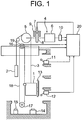
- FIG. 1 is a schematic diagram illustrating an elevator apparatus according to a first embodiment of the present invention.
- a car 1 and a counterweight 2 which are suspended within a hoistway by a main rope 3 as suspension means, are raised/lowered within the hoistway due to a driving force of a hoisting machine 4.
- the hoisting machine 4 has a drive sheave 5 around which the main rope 3 is wound, a hoisting machine motor 6 for rotating the drive sheave 5, and a brake device 7 for braking rotation of the drive sheave 5.
- the brake device 7 includes a brake drum (brake wheel) 8 connected to the same shaft to which the drive sheave 5 is connected, a brake shoe 9 which is moved into contact with and away from the brake drum, a brake spring for pressing the brake shoe 9 against the brake drum 8 to apply a braking force to the brake drum 8, and an electromagnetic magnet for separating the brake shoe 9 away from the brake drum 8 against the brake spring to release the braking force.
- the hoisting machine motor 6 is provided with a hoisting machine encoder portion 10 for generating a signal according to a rotational speed of a rotary shaft of the hoisting machine motor, that is, a rotational speed of the drive sheave 5.
- the hoisting machine encoder portion 10 includes a first hoisting machine encoder 10a and a secondhoistingmachine encoder 10b ( FIG. 2 ), each for generating an independent detection signal.
- a top hoistway switch 11 In the proximity of a top terminal landing of the hoistway, a top hoistway switch 11 is provided. In the proximity of a bottom terminal landing of the hoistway, a bottom hoistway switch 12 is provided. Each of the hoistway switches 11 and 12 is used as a position correction switch for detecting an absolute position of the car 1 to correct car position information. An operation cam 13 for operating the hoistway switches 11 and 12 is mounted to the car 1.
- a car buffer 14 and a counterweight buffer 15 are provided.
- the car buffer 14 is located immediately below the car 1, whereas the counterweight buffer 15 is located immediately below the counterweight 2.
- a governor sheave 16 In an upper part of the hoistway, a governor sheave 16 is provided. In a lower part of the hoistway, a tension sheave 17 is provided. A governor rope (overspeed detection rope) 18 is wound around the governor sheave 16 and the tension sheave 17. Both ends of the governor rope 18 are connected to the car 1. The governor rope 18 is made to circulate along with the lowering/raising of the car 1. As a result, the governor sheave 16 and the tension sheave 17 are rotated at a speed according to a running speed of the car 1.
- the governor sheave 16 is provided with a governor encoder portion 19 for generating a signal according to a rotational speed of the governor sheave 16 , that is , a speed of the car 1.
- the governor encoder portion 19 includes a first governor encoder 19a and a second governor encoder 19b ( FIG. 10 ), each for generating an independent detection signal.
- the brake device 7 is controlled by a brake control device 20. Signals from the hoisting machine encoder portion 10, the hoistway switches 11 and 12, and the governor encoder portion 19 are input to the brake control device 20. A signal according to a current of the electromagnetic magnet of the brake device 7 is also input to the brake control device 20.
- the brake control device 20 controls a braking force of the brake device 7 in response to the signal from the hoisting machine encoder portion 10 and the current signal of the electromagnetic magnet. Moreover, for emergency stop of the car 1, the brake control device 20 controls the braking force of the brake device 7 to prevent a deceleration of the car 1 from being excessively large.
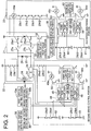
- FIG. 2 is a circuit diagram illustrating the brake control device 20 of FIG. 1 .
- the brake control device 20 has a first brake control portion 21 and a second brake control portion 22 that control the brake device 7 independently of each other, and an overspeed monitoring portion 23.
- the electromagnet of the brake device 7 is provided with a brake coil (electromagnetic coil) 24.
- a brake coil electromagnet
- the electromagnet is excited to generate an electromagnetic force for canceling the braking force of the brake device 7, whereby the brake shoe 9 is opened away from the brake drum 8.
- the braking force of the brake device 7 can be controlled.
- a circuit in which a discharge resistor 25 and a first discharge diode 26 are connected in series is connected in parallel to the brake coil 24.
- a second discharge diode 31 is connected in parallel to the brake coil 24 at both ends thereof via a first electromagnetic relay 27a and a second electromagnetic relay 27b, and a third electromagnetic relay 29e1 and a fourth electromagnetic relay 29e2, respectively.
- the third and fourth electromagnetic relays 29e1 and 29e2 are normally-closed relays.
- the third electromagnetic relay 29e1 is connected in series to the first electromagnetic relay 27a.
- the fourth electromagnetic relay 29e2 is connected in series to the second electromagnetic relay 27b.
- the brake coil 24 is connected on the first electromagnetic relay 27a side and the third electromagnetic relay 29e1 side thereof to a power supply.
- the brake coil 24 is connected on the second electromagnetic relay 27b side and the fourth electromagnetic relay 29e2 side thereof to a ground via a brake switch 32.
- a semiconductor switch is employed as the brake switch 32.
- the turning ON/OFF of the brake switch 32 is controlled by a brake determination portion 33.
- the brake determination portion 33 turns the brake switch 32 ON to energize the brake coil 24, thereby canceling the braking force of the brake device 7.
- the brake determination portion 33 turns the brake switch 32 OFF to deenergize the brake coil 24, thereby causing the brake device 7 to generate the braking force (to hold the car 1 stationary).
- the brake determination portion 33 turns the brake switch 32 OFF and opens the electromagnetic relays 27a and 27b, thereby deenergizing the brake coil 24 and causing the brake device 7 to perform braking operation.
- the car 1 is stopped as an emergency measure.
- the electromagnetic relays 27a and 27b are opened, the discharge resistor 25 and the first discharge diode 26 swiftly reduce an induction current flowing through the brake coil 24 to precipitate generation of the braking force.
- a function of the brake determination portion 33 is realized by, for example, a first microcomputer provided in an elevator control device for controlling traveling of the car 1. That is, a program for realizing the function of the brake determination portion 33 is stored in the first microcomputer.
- the first brake control portion (main control portion) 21 includes the electromagnetic relays 27a, 27b, 29e1, and 29e2, the second discharge diode 31, the brake switch 32, and the brake determination portion 33.
- a first car position detecting portion 38 includes the first governor encoder 19a and the hoistway switches 11 and 12.
- a second car position detecting portion 39 includes the second governor encoder 19b and the hoistway switches 11 and 12.
- An endpoint node between the brake coil 24 and the first electromagnetic relay 27a is connected to the power supply via a circuit in which a fifth electromagnetic relay 29a1 and a sixth electromagnetic relay 29b1 are connected in series.
- An endpoint node between the brake coil 24 and the second electromagnetic relay 27b is connected to the ground via a circuit in which a seventh electromagnetic relay 29a2, an eighth electromagnetic relay 29b2, a first deceleration control switch 42, and a second deceleration control switch 43 are connected in series.
- a third discharge diode 44 is connected in parallel to a circuit in which the fifth electromagnetic relay 29a1, the sixth electromagnetic relay 29b1, the brake coil 24, the seventh electromagnetic relay 29a2, and the eighth electromagnetic relay 29b2 are connected in series.
- the first deceleration control switch 42 and the second deceleration control switch 43 each are switches for controlling the deceleration of the car 1 at the time of emergency braking of the car 1.
- Semiconductor switches are employed as the deceleration control switches 42 and 43.
- the deceleration control performed by the first deceleration control switch 42 and the second deceleration control switch 43 is validated when all the electromagnetic relays 29a1, 29b1, 29a2, and 29b2 are closed, and is invalidated when any one of the electromagnetic relays 29a1, 29b1, 29a2, and 29b2 is open.
- the turning ON/OFF of the first deceleration control switch 42 is controlled by a first calculation portion 45.
- the first calculation portion 45 calculates a position y[m] of the car, a speed V[m/s] of the car, and a deceleration ⁇ [m/s 2 ] of the car based on the signals from the first and second encoders 10a and 10b and signals from the first and second car position detecting portions 38 and 39.
- the first calculation portion 45 controls the turning ON/OFF of the first deceleration control switch 42 based on the position of the car, the speed of the car, the deceleration of the car, and the current value of the brake coil 24.
- the first calculation portion 45 is constituted by a second microcomputer.
- the turning ON/OFF of the second deceleration control switch 43 is controlled by a second calculation portion 46.
- the second calculation portion 46 calculates the position y[m] of the car, the speed V[m/s] of the car, and the deceleration ⁇ [m/s 2 ] of the car independently of the first calculation portion 45 based on the signals from the first and second encoders 10a and 10b and the signals from the first and second car position detecting portions 38 and 39.
- the second calculation portion 46 also controls the turning ON/OFF of the second deceleration control switch 43 based on the position of the car, the speed of the car, the deceleration of the car, and the current value of the brake coil 24.
- the second calculation portion 46 is constituted by a third microcomputer.
- a two-port RAM 47 is connected between the first calculation portion 45 and the second calculation portion 46.
- a deceleration control determination portion 48 has the first calculation portion 45, the second calculation portion 46, and the two-port RAM 47.
- the fifth electromagnetic relay 29a1 and the seventh electromagnetic relay 29a2 are opened/closed by a first drive coil 49a.
- a first drive coil control switch 50 for turning ON/OFF the supply of a current to the first drive coil 49a is connected between the first drive coil 49a and the ground.
- a semiconductor switch is employed as the first drive coil control switch 50. The turning ON/OFF of the first drive coil control switch 50 is controlled by the first calculation portion 45.
- the sixth electromagnetic relay 29b1 and the eighth electromagnetic relay 29b2 are opened/closed by a second drive coil 49b.
- a second drive coil control switch 51 for turning ON/OFF the supply of a current to the second drive coil 49b is connected between the second drive coil 49b and the ground.
- a semiconductor switch is employed as the second drive coil control switch 51. The turning ON/OFF of the second drive coil control switch 51 is controlled by the second calculation portion 46.
- a ninth electromagnetic relay 29a3 that is opened/closed in accordance with the opening/closing of the fifth electromagnetic relay 29a1, and a tenth electromagnetic relay 29a4 that is opened/closed in accordance with the opening/closing of the seventh electromagnetic relay 29a2 are connected in series between the power supply and the ground via a resistor 52.
- the first calculation portion 45 detects a voltage of the resistor 52 on the power supply side. Thus, the first calculation portion 45 monitors the open/closed states of the fifth electromagnetic relay 29a1 and the seventh electromagnetic relay 29a2.
- An eleventh electromagnetic relay 29b3 that is opened/closed in accordance with the opening/closing of the sixth electromagnetic relay 29b1, and a twelfth electromagnetic relay 29b4 that is opened/closed in accordance with the opening/closing of the eighth electromagnetic relay 29b2 are connected in series between the power supply and the ground via a resistor 53.
- the second calculation portion 46 detects a voltage of the resistor 53 on the power supply side.
- the second calculation portion 46 monitors the open/closed states of the sixth electromagnetic relay 29b1 and the eighth electromagnetic relay 29b2.
- the first calculation portion 45 and the second calculation portion 46 make a comparison between a command for the drive coil control switch 50 and the open/closed states of the electromagnetic relays 29a1, 29b1, 29a2, and 29b2 and a comparison between a command for the drive coil control switch 51 and the open/closed states of the electromagnetic relays 29a1, 29b1, 29a2, and 29b2, respectively, thereby determining whether or not a malfunction such as an adhesion of a contact or the like has occurred in each of the electromagnetic relays 29a1, 29b1, 29a2, and 29b2.
- the first calculation portion 45 compares a signal from the first current detector 34 with a signal from the second current detector 35 to determine whether or not a malfunction has occurred in the first current detector 34 and the second current detector 35.
- the first calculation portion 45 compares the signal from the first hoisting machine encoder 10a with the signal from the second hoisting machine encoder 10b to determine whether or not a malfunction has occurred in the first hoisting machine encoder 10a and the second hoisting machine encoder 10b.
- the first calculation portion 45 compares the signal from the first car position detecting portion 38 and the signal from the second car position detecting portion 39 with each other to determine whether or nor a malfunction has occurred in the first car position detecting portion 38 and the second car position detecting portion 39.
- the first calculation portion 45 receives a calculation result obtained by the second calculation portion 46 via the two-port RAM 47 , and compares the received calculation result with a calculation result obtained by the first calculation portion 45, thereby determining whether or not a malfunction has occurred in the first calculation portion 45 and the second calculation portion 46.
- the second calculation portion 46 compares the signal from the first current detector 34 with the signal from the second current detector 35 to determine whether or not a malfunction has occurred in the first current detector 34 and the second current detector 35.
- the second calculation portion 46 compares the signal from the first hoisting machine encoder 10a with the signal from the second hoisting machine encoder 10b to determine whether or not a malfunction has occurred in the first hoisting machine encoder 10a and the second hoisting machine encoder 10b.
- the second calculation portion 46 compares the signal from the first car position detecting portion 45 and the signal from the second car position detecting portion 39 with each other to determine whether or nor a malfunction has occurred in the first car position detecting portion 38 and the second car position detecting portion 39.
- the second calculation portion 46 receives a calculation result obtained by the first calculation portion 45 via the two-port RAM 47 , and compares the received calculation result with a calculation result obtained by the second calculation portion 46, thereby determining whether or not a malfunction has occurred in the first calculation portion 45 and the second calculation portion 46.
- each of the first calculation portion 45 and the second calculation portion 46 outputs a command to open corresponding ones of the electromagnetic relays 29a1, 29b1, 29a2, and 29b2, and outputs a malfunction detection signal to a first malfunction reporting portion 54.
- the malfunction reporting portion 54 informs the elevator control device that some malfunction has occurred in the second brake control portion 22.
- the elevator control device stops the car 1 at, for example, the nearest floor, halts the traveling of the elevator apparatus, and causes the elevator apparatus to operate to report the occurrence of the malfunction to the outside.
- the second brake control portion (deceleration control portion) 22 has the electromagnetic relays 29a1, 29a2, 29a3, 29a4, 29b1, 29b2, 29b3, and 29b4, the deceleration control switches 42 and 43, the discharge diode 44, the deceleration control determination portion 48, the drive coils 49a and 49b, the drive coil control switches 50 and 51, the resistors 52 and 53, and the first malfunction reporting portion 54.
- the third electromagnetic relay 29e1 and the fourth electromagnetic relay 29e2 are driven by a fifth drive coil 49e.
- a thirteenth electromagnetic relay 29c1, a fourteenth electromagnetic relay 29c2, a fifteenth electromagnetic relay 29d1, and a sixteenth electromagnetic relay 29d2 are connected in series between the fifth drive coil 49e and the ground.
- the thirteenth electromagnetic relay 29c1 and the fourteenth electromagnetic relay 29c2 are opened/closed by a third drive coil 49c.
- a third drive coil control switch 55 for turning ON/OFF the supply of a current to the third drive coil 49c is connected between the third drive coil 49c and the ground.
- a semiconductor switch is employed as the third drive coil control switch 55.
- the turning ON/OFF of the third drive coil control switch 55 is controlled by a third calculation portion 56.
- the third calculation portion 56 calculates the position of the car and the speed of the car based on the signals from the first and second car position detecting portions 38 and 39.
- the third calculation portion 56 controls the turning ON/OFF of the third drive coil control switch 55 based on the position of the car and the speed of the car.
- the third calculation portion 56 is constituted by a fourth microcomputer.
- the fifteenth electromagnetic relay 29d1 and the sixteenth electromagnetic relay 29d2 are opened/closed by a fourth drive coil 49d.
- a fourth drive coil control switch 57 for turning ON/OFF the supply of a current to the fourth drive coil 49d is connected between the fourth drive coil 49d and the ground.
- a semiconductor switch is employed as the fourth drive coil control switch 57.
- the turning ON/OFF of the fourth drive coil control switch 57 is controlled by a fourth calculation portion 58.
- the fourth calculation portion 58 calculates the position of the car and the speed of the car based on the signals from the first and second car position detecting portions 38 and 39.
- the fourth calculation portion 58 controls the turning ON/OFF of the fourth drive coil control switch 57 based on the position of the car and the speed of the car.
- the fourth calculation portion 58 is constituted by a fifth microcomputer.
- a two-port RAM 59 is connected between the third calculation portion 56 and the fourth calculation portion 58.
- a seventeenth electromagnetic relay 29c3 that is opened/closed in accordance with the opening/closing of the thirteenth electromagnetic relay 29c1, and an eighteenth electromagnetic relay 29c4 that is opened/closed in accordance with the opening/closing of the fourteenth electromagnetic relay 29c2 are connected in series between the power supply and the ground via a resistor 60.
- the third calculation portion 56 detects a voltage of the resistor 60 on the power supply side.
- the third calculation portion 56 monitors the open/closed states of the thirteenth electromagnetic relay 29c1 and the fourteenth electromagnetic relay 29c2.
- a nineteenth electromagnetic relay 29d3 that is opened/closed in accordance with the opening/closing of the fifteenth electromagnetic relay 29d1, and a twentieth electromagnetic relay 29d4 that is opened/closed in accordance with the opening/closing of the sixteenth electromagnetic relay 29d2 are connected in series between the power supply and the ground via a resistor 61.
- the fourth calculation portion 58 detects a voltage of the resistor 61 on the power supply side.
- the fourth calculation portion 58 monitors the open/closed states of the fifteenth electromagnetic relay 29d1 and the sixteenth electromagnetic relay 29d2.
- the third calculation portion 56 and the fourth calculation portion 58 make a comparison between a command for the drive coil control switch 55 and the open/closed states of the electromagnetic relays 29c1, 29c2 , 29d1, and 29d2 and a comparison between a command for the drive coil control switch 57 and the open/closed states of the electromagnetic relays 29c1, 29c2, 29d1, and 29d2, respectively, thereby determining whether or not a malfunction such as an adhesion of a contact or the like has occurred in each of the electromagnetic relays 29c1, 29c2, 29d1, and 29d2.
- the third calculation portion 56 receives a calculation result obtained by the fourth calculation portion 58 via the two-port RAM 59, and compares the received calculation result with a calculation result obtained by the third calculation portion 56, thereby determining whether or not a malfunction has occurred in the third calculation portion 56 and the fourth calculation portion 58.
- the fourth calculation portion 58 receives a calculation result obtained by the third calculation portion 56 via the two-port RAM 59, and compares the received calculation result with a calculation result obtained by the fourth calculation portion 58, thereby determining whether or not a malfunction has occurred in the third calculation portion 56 and the fourth calculation portion 58.
- each of the third calculation portion 56 and the fourth calculation portion 58 outputs a malfunction detection signal to a second malfunction reporting portion 62.
- the malfunction detection signal is input to the second malfunction reporting portion 62
- the second malfunction reporting portion 62 informs the elevator control device that some malfunction has occurred in the overspeed monitoring portion 23.
- the elevator control device stops the car 1 at, for example, the nearest floor, halts the traveling of the elevator apparatus, and causes the elevator apparatus to operate to report the occurrence of the malfunction to the outside.
- the overspeed monitoring portion 23 has the electromagnetic relays 29c1, 29c2, 29c3, 29c4, 29d1, 29d2, 29d3, and29d4, the drive coils 49c, 49d, and 49e, the drive coil control switches 55 and 57, the third calculation portion 56 and the fourth calculation portion 58, the two-port RAM 59, the resistors 60 and 61, and the second malfunction reporting portion 62.
- the overspeed monitoring portion 23 can stop the car 1 as an emergency measure, independently of the first brake control portion 21. Moreover, the overspeed monitoring portion 23 monitors the speed of the car 1 independently to detect the overspeed of the car 1 independently, without using the signals from the first brake control portion 21 and the elevator control device.
- FIG. 3 is a flowchart illustrating deceleration control operation of each of the first calculation portion 45 and the second calculation portion 46 of FIG. 2 .
- the first calculation portion 45 and the second calculation portion 46 perform the processings illustrated in FIG. 3 at the same time and in tandem with each other.
- the first calculation portion 45 and the second calculation portion 46 first perform initial settings of a plurality of parameters required for the processings (Step S1).
- a speed (drive sheave speed) V0[m/s] of the car which is used to determine whether or not the car 1 is stopped, a speed V1[m/s] of the car at which deceleration control is stopped, a threshold value I0[A] of the current value of the brake coil 24, a first threshold value ⁇ 1[m/s 2 ] of the deceleration of the car, and a second threshold value ⁇ 2[m/s 2 ] of the deceleration of the car ( ⁇ 1 ⁇ 2) are set as the parameters.
- each of the first calculation portion 45 and the second calculation portion 46 acquires signals from the first encoder 10a and the second encoder 10b, signals from the first current detector 34 and the second current detector 35, and signals from the first car position detecting portion 38 and the second car position detecting portion 39 in a predetermined cycle (Step S2). Then, the first calculation portion 45 and the second calculation portion 46 calculate the speed V[m/s] of the car and the deceleration ⁇ [m/s 2 ] of the car based on the signals from the first encoder 10a and the second encoder 10b (Step S3).
- the first calculation portion 45 and the second calculation portion 46 determine whether or not the car 1 is in emergency stop operation (Step S4). More specifically, when the speed of the car (rotational speed of the motor) is higher than the speed V0 for determining whether or not the car is stopped and the current value of the brake coil 24 is smaller than the current value 10 for determining whether or not the car is stopped, the first calculation portion 45 and the second calculation portion 46 determine that the car 1 is in emergency stop operation. When the car 1 is not in emergency stop operation, the first calculation portion 45 and the second calculation portion 46 open all the electromagnetic relays 29a1, 29b1, 29a2, and 29b2 (Step S10).
- the first calculation portion 45 and the second calculation portion 46 determine whether or not the deceleration ⁇ of the car is higher than the first threshold value ⁇ 1 (Step S5). When ⁇ 1, the first calculation portion 45 and the second calculation portion 46 open all the electromagnetic relays 29a1, 29b1, 29a2, and 29b2 (Step S10). When ⁇ > ⁇ 1, the first calculation portion 45 and the second calculation portion 46 close all the electromagnetic relays 29a1, 29b1, 29a2, and 29b2 (Step S6).
- the supply of a current to the hoisting machine motor 6 is also shut off. Therefore, the car 1 may be accelerated or decelerated due to an imbalance between a load on the car 1 side and a load of the counterweight 2 from a moment when an emergency stop command is issued to a moment when a braking force is actually applied.
- the first calculation portion 45 and the second calculation portion 46 determine that the car 1 is accelerated immediately after the issuance of the emergency stop command, and open the electromagnetic relays 29a1, 29b1, 29a2, and 29b2 to apply the braking force swiftly.
- the first calculation portion 45 and the second calculation portion 46 determine that the car 1 is decelerated, and close the electromagnetic relays 29a1, 29b1, 29a2, and 29b2 to perform deceleration control, with a view to preventing the deceleration from becoming excessively high.
- the first calculation portion 45 and the second calculation portion 46 determine whether or not the deceleration ⁇ of the car is larger than the second threshold value ⁇ 2 (Step S7).
- the first calculation portion 45 and the second calculation portion 46 turn the deceleration control switches 42 and 43 ON/OFF with a preset switching duty (e.g. , 50%) to suppress the deceleration ⁇ of the car (Step S8).
- a preset switching duty e.g. , 50%
- the first calculation portion 45 and the second calculation portion 46 hold the deceleration control switches 42 and 43 open. After that, the first calculation portion 45 and the second calculation portion 46 determine whether to stop control or not (Step S9). In determining whether to stop control or not, the first calculation portion 45 and the second calculation portion 46 determine whether or not the speed V of the car is smaller than the threshold value V1.
- V ⁇ V1 the first calculation portion 45 and the second calculation portion 46 directly return to an input processing (Step S2).
- V ⁇ V1 the first calculation portion 45 and the second calculation portion 46 open all the electromagnetic relays 29a1, 29b1, 29a2, and 29b2 (Step S10), and then return to the input processing (Step S2).
- FIG. 4 is an explanatory diagram illustrating how the speed of the car, the deceleration of the car, the current of the brake coil 24, the states of the electromagnetic relays 29a1, 29b1, 29a2, and 29b2, and the states of the deceleration control switches 42 and 43 change with time in the case where the car 1 decelerates immediately after the issuance of an emergency stop command.
- the car 1 When the emergency stop command is issued, the car 1 immediately starts to decelerate. Then, when the deceleration reaches ⁇ 1 at a time instant T2, the electromagnetic relays 29a1, 29b1, 29a2, and 29b2 are closed. When the deceleration reaches ⁇ 2 at a time instant T3, the deceleration control switches 42 and 43 are turned ON/OFF. After that, when the speed of the car becomes lower than V1, the electromagnetic relays 29a1, 29b1, 29a2, and 29b2 are opened, whereby deceleration control performed by the deceleration control switches 42 and 43 is stopped.
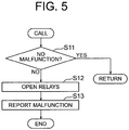
- FIG. 5 is a flowchart illustrating abnormality diagnosis operation of each of the first calculation portion 45 and the second calculation portion 46 of FIG. 2 .
- the first calculation portion 45 and the second calculation portion 46 call diagnosis processings illustrated in FIG. 5 as soon as the processings following the input processing (Step S2) of FIG. 3 are completed.
- the first calculation portion 45 and the second calculation portion 46 make a determination on the consistency of values input from the sensors and values calculated by the calculation portions 45 and 46 (Step S11). More specifically, when a difference between the input values and a difference between the calculated values are within each of predetermined ranges , the first calculation portion 45 and the second calculation portion 46 determine that there is no abnormality, and return to the subsequent processing illustrated in FIG. 3 .
- the first calculation portion 45 and the second calculation portion 46 determine that there is an abnormality, open the electromagnetic relays 29a1, 29b1, 29a2, and 29b2 (Step S12), and output malfunction detection signals to the first malfunction reporting portion 54 (Step S13).
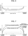
- FIG. 6 is a graph illustrating a relation between the first threshold value and the second threshold value of the deceleration of the car, which are set in each of the first calculation portion 45 and the second calculation portion 46 illustrated in FIG. 2 , and the position of the car.
- the first threshold value ⁇ 1 and the second threshold value ⁇ 2 are set in the first calculation portion 45 to vary according to the position of the car.
- the first threshold value ⁇ 1 and the second threshold value ⁇ 2 are also set in the second calculation portion 46. More specifically, the first threshold value ⁇ 1 and the second threshold value ⁇ 2 in the proximity of the terminal landings are set to gradually increase toward the terminal landings.
- FIG. 7 is a graph illustrating an overspeed monitoring pattern set in each of the third calculation portion 56 and the fourth calculation portion 58 illustrated in FIG. 2 .
- the overspeed monitoring pattern is set to vary according to the position of the car. Specifically, the overspeedmonitoring pattern is set to ensure a predetermined margin with respect to a normal running pattern when the car 1 normally runs from one of the terminal landings to the other terminal landing. Therefore, the overspeed monitoring pattern in the proximity of each of the terminal landings is set to gradually decrease toward the terminal landing.
- Each of the third calculation portion 56 and the fourth calculation portion 58 monitors the speed of the car in an independent fashion.
- each of the third calculation portion 56 and the fourth calculation portion 58 turns OFF a corresponding one of the drive coil control switches 55 and 57.
- the drive coils 49c and 49d are deenergized.
- the electromagnetic relays 29c1, 29c2, 29d1 and 29d2 are opened to deenergize the drive coil 49e.
- the electromagnetic relays 29e1 and 29e2 are opened to stop the car 1 as an emergency measure.
- the deceleration control at this time is performed by the second brake control portion 22.
- the second brake control portion 22 corresponding to the deceleration control portion is provided independently of the first brake control portion 21 corresponding to the main control portion. Therefore, even when a malfunction occurs in the deceleration control portion, the car can be stopped more reliably.
- the second brake control portion 22 includes the first calculation portion 45 and the second calculation portion 46 , each for executing the operation of reducing the braking force of the brake device 7 by the calculation processing independently of each other, and hence the reliability can be improved.
- the second threshold value ⁇ 2 is set to vary according to the position of the car in each of the first calculation portion 45 and the second calculation portion 46 as illustrated in FIG. 6 . Therefore, a great difference in riding comfort at the time of emergency stop depending on the position of the car can be prevented from being generated.
- the second threshold value ⁇ 2 in the proximity of each of the terminal landings is set to gradually increase toward the terminal landing. Therefore, in the proximity of the terminal landing, a stop distance from the issuance of the emergency stop command to the stop of the car 1 can be reduced. In addition, a speed at which the car 1 and the counterweight 2 respectively collide against the car buffer 14 and the counterweight buffer 15 can be reduced. Accordingly, a volume of each of the car buffer 14 and the counterweight buffer 15 can be reduced.
- first calculation portion 45 and the second calculation portion 46 compare calculation results thereof with each other to detect the occurrence of a malfunction in at least one of the first calculation portion 45 and the second calculation portion 46. Therefore, further improvement of reliability can be achieved.
- the second brake control portion 22 invalidates deceleration control performed by the second brake control portion 22. Therefore, the car 1 can be stopped more reliably even in the event of a malfunction in at least one of the calculation portions 45 and 46.
- the second brake control portion 22 determines that the brake device 7 is in emergency stop operation. Therefore, emergency braking operation can be detected more reliably, independently of the first brake control portion 21.
- the brake control device 20 further includes the overspeedmonitoring portion 23 for stopping the car 1 as an emergency measure when the speed of the car reaches the preset overspeed.
- the overspeed monitoring portion 23 the overspeed monitoring pattern which gradually decreases in the proximity of each of the terminal landings toward each of the terminal landings is set. Therefore, the speed at which the car 1 and the counterweight 2 respectively collide against the car buffer 14 and the counterweight buffer 15 can be further reduced, and accordingly the volume of each of the car buffer 14 and the counterweight buffer 15 can be further reduced. Moreover, a pit depth size and an overhead size of the hoistway can be reduced.
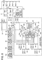
- FIG. 8 is a circuit diagram illustrating a brake control device of an elevator apparatus according to a second embodiment of the present invention.
- the function of the third calculation portion 56 according to the first embodiment is included in the first calculation portion 45, whereas the function of the fourth calculation portion 58 according to the first embodiment is included in the second calculation portion 46.
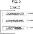
- FIG. 9 is a flowchart illustrating an operation of each of the first calculation portion 45 and the second calculation portion 46 illustrated in FIG. 8 .
- Each of the first calculation portion 45 and the second calculation portion 46 repeatedly executes malfunction detection processing (Step S14), overspeed detection processing (Step S15), and brake control processing (Step S16) in a predetermined cycle.
- each of the first calculation portion 45 and the second calculation portion 46 sequentially executes the above-mentioned processing in a one-by-one manner by single tasking.
- the remaining structure is the same as that of the first embodiment.
- the size and the cost of the brake control device can be reduced while the reliability provided by a duplex system is maintained.
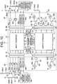
- FIG. 10 is a circuit diagram illustrating a brake control device of an elevator apparatus according to a third embodiment of the present invention.
- input/output signals to/from the first calculation portion 45 and the second calculation portion 46 in the circuit configuration described in the second embodiment are integrated by using a plurality of interfaces.
- a multiplex calculation portion 71 includes the first calculation portion 45, the second calculation portion 46, the two-port RAM 47, the malfunction reporting portion 54, an input interface 72, an output interface 73, a first input connector 74, a second input connector 75, a first output connector 76, a second output connector 77, and first to fourth data buses 78 to 81.
- Input signals from the exterior of the multiplex calculation portion 71 are input to the input interface 72 through the first input connector 74 and the second input connector 75.
- the input signals are distributed to the first data bus 78 and the second data bus 79 through the input interface 72 to be input to the first calculation portion 45 and the second calculation portion 46.
- Output signals from the first calculation portion 45 and the second calculation portion 46 are input to the output interface 73 through the third data bus 80 and the fourth data bus 81 to be externally output from the output interface 73 through the first output connector 76 and the second output connector 77.
- each of the input interface 72 and the output interface 73 has a buffering function of increasing the stability of each of the signals.
- a car position detection interface portion 82 includes a car position signal connector 83, an overspeed detection signal connector 84, first to sixth buffers 85a to 85f, a first governor encoder interface 86a, and a second governor encoder interface 86b.
- the car position signal connector 83 is connected to the first input connector 74.
- the overspeed detection signal connector 84 is connected to the first output connector 76.
- the buffers 85a to 85f serve to increase the stability and a noise resistance characteristic of each of the signals.
- an optical coupler is used as each of the buffers 85a to 85f.
- Voltage signals of the resistors 60 and 61 are transmitted to the car position signal connector 83 through the first buffer 85a and the second buffer 85b. Signals from the hoistway switches 11 and 12 are transmitted to the car position signal connector 83 through the third buffer 85c and the fourth buffer 85d. Signals from the first governor encoder 19a and the second governor encoder 19b are transmitted to the car position signal connector 83 through the encoder interfaces 86a and 86b.
- the fifth buffer 85e is provided between the third drive coil control switch 55 and the overspeed detection signal connector 84, whereas the sixth buffer 85f is provided between the fourth drive coil control switch 57 and the overspeed detection signal connector 84.
- a brake control interface portion 87 includes a car speed signal connector 88, a deceleration control signal connector 89, seventh to twelfth buffers 85g to 851, a first hoisting machine encoder interface 90a, and a second hoisting machine encoder interface 90b.
- the car speed signal connector 88 is connected to the second input connector 75.
- the deceleration control signal connector 89 is connected to the second output connector 77.
- the buffers 85g to 851 serve to increase the stability and the noise resistance characteristic of each of the signals.
- an optical coupler is used as each of the buffers 85g to 851, for example.
- Voltage signals of the resistors 52 and 53 are transmitted to the car speed signal connector 88 through the seventh buffer 85g and the eighth buffer 85h. Signals from the first hoisting machine encoder 10a and the second hoisting machine encoder 10b are transmitted to the car speed signal connector 88 through the encoder interfaces 90a and 90b.
- a ninth buffer 85i is provided between the first drive coil control switch 50 and the deceleration control signal connector 89, a tenth buffer 85j is provided between the first deceleration control switch 42 and the deceleration control signal connector 89, an eleventh buffer 85k is provided between the second deceleration control switch 43 and the deceleration control signal connector 89, and a twelfth buffer 851 is provided between the second drive coil control switch 51 and the deceleration control signal connector 89.
- the signals are transmitted and received between each of the interfaces 82 and 87 and the multiplex calculation portion 71 according to the same protocol.
- the reception/transmission of the signals of the duplex system is performed in an integrated fashion by using the single input interface 72 and the single output interface 73. Therefore, the number of components can be reduced to simplify the configuration.
- the input signals to the input interface 72 are collectively input through the two input connectors 74 and 75 , whereas the output signals from the output interface 73 are collectively output through the two output connectors 76 and 77. Therefore, the configuration can be further simplified.
- the same protocol is used for the transmission/reception of the signals through the connectors 74, 75, 76, 77, 83, 84, 88, and 89, and hence, for example, a function of inhibiting the car 1 from running with a car door or a landing door being open can be easily realized by the multiplex calculation portion 71.
- the determination on emergency stop is made from the speed of the car and the current value of the brake coil 24.
- the determination on emergency stop may be made in consideration of a derivative value of the current value of the brake coil 24 as well as the above-mentioned values. More specifically, when the speed of the car is higher than a predetermined speed, the current of the brake coil 24 is smaller than a predetermined value, and the derivative value of the current value of the brake coil 24 is negative, it is determined that the car is being stopped as an emergency measure. Thus, the occurrence of erroneous detection resulting from vibrations within the car in the process of stopping the car can be avoided.
- the single brake device 7 is illustrated in the foregoing examples.
- a plurality of the brake devices 7 connected in parallel may be employed.
- the other brake devices are in operation. Therefore, the reliability of the entire elevator apparatus can be improved.
- the brake device 7 is provided on the hoisting machine 4.
- the brake device 7 may be provided at another location.
- the brake device may be a car brake mounted on the car, or a rope brake for gripping the main rope to brake the car.
- suspension means for example, a rope having a circular cross section or a belt having a flat sectional shape can be used.
Description
- The present invention relates to an elevator apparatus including a brake control device capable of controlling a deceleration of a car at a time of emergency braking.
- In a conventional brake device for an elevator, a braking force of an electromagnetic brake is controlled at a time of emergency braking so that a deceleration of a car becomes equal to a predetermined value, based on a deceleration command value and a speed signal (for example, see Patent Document 1).
- Moreover, in a conventional elevator apparatus, if the car is running toward a terminal landing in proximity of the terminal landing at a time of issuance of an emergency stop command, the car is decelerated swiftly at a high deceleration to be stopped. At the time of issuance of the emergency stop command, the car is decelerated at a sufficiently low deceleration to be stopped except for a case where the car is running toward the terminal landing in the proximity thereof (for example, see Patent Document 2).
-
- Patent Document 1:
JP 07-157211 A - Patent Document 2:
JP 2006-306517 A - Document
JP-H-0840662 - In the conventional brake device described in
Patent Document 1, both a basic operation of emergency braking and an operation of controlling the braking force are performed by a single brake control unit. Therefore, when the deceleration of the car becomes excessively high due to a malfunction in the brake control unit or the like, passengers feel uncomfortable. On the contrary, when the deceleration of the car becomes excessively low, a braking distance of the car becomes longer. Further, in the case of the conventional elevator apparatus described inPatent Document 2, the deceleration of the car at the time of emergency stop intermittently changes depending on a position of the car. Therefore, a great difference is generated in riding comfort at the time of emergency stop between the proximity of the terminal landing and a middle landing. - The present invention has been made to solve the above-mentioned problems, and has an object of obtaining an elevator apparatus that makes it possible to stop a car more reliably even in event of a malfunction in a deceleration control portion and to prevent generation of a great difference in riding comfort at the time of emergency stop depending on the position of the car.
- An elevator apparatus according to the present invention comprises: a hoisting machine including a drive sheave and a motor for rotating the drive sheave; suspension means wound around the drive sheave; a car suspended by the suspension means to be raised and lowered by the hoisting machine; a brake device for braking running of the car; and a brake control device for controlling the brake device, wherein: the brake control device includes: a first brake control portion for operating the brake device upon detection of an abnormality to stop the car as an emergency measure; and a second brake control portion for reducing a braking force of the brake device when a deceleration of the car becomes equal to or higher than a threshold value at a time of an emergency braking operation of the first brake control portion; the second brake control portion includes a first calculation portion and a second calculation portion, each independently executing an operation of reducing the braking force of the brake device by calculation processing; the threshold value is set in the first calculation portion to vary according to a car position; and the threshold value is set in the second calculation portion as in a case of the first calculation portion.
-
-
FIG. 1 is a configuration diagram illustrating an elevator apparatus according to a first embodiment of the present invention. -
FIG. 2 is a circuit diagram illustrating a brake control device illustrated inFIG. 1 . -
FIG. 3 is a flowchart illustrating a deceleration control operation of each of first and second calculation portions illustrated inFIG. 2 . -
FIG. 4 is an explanatory diagram illustrating how a speed of a car, a deceleration of the car, a current of a brake coil, a state of each of electromagnetic relays , and a state of each of deceleration control switches change with time in a case where the car decelerates immediately after issuance of an emergency stop command. -
FIG. 5 is a flowchart illustrating an abnormality diagnosis operation of each of the first and second calculation portions illustrated inFIG. 2 . -
FIG. 6 is a graph illustrating a relation between first and second threshold values of the deceleration of the car, which are set in each of the first and second calculation portions illustrated inFIG. 2 , and a position of the car. -
FIG. 7 is a graph illustrating an overspeed monitoring pattern set in each of third and fourth calculation portions illustrated inFIG. 2 . -
FIG. 8 is a circuit diagram illustrating a brake control device of an elevator apparatus according to a second embodiment of the present invention. -
FIG. 9 is a flowchart illustrating an operation of each of first and second calculation portions illustrated inFIG. 8 . -
FIG. 10 is a circuit diagram illustrating a brake control device of an elevator apparatus according to a third embodiment of the present invention. - Preferred embodiments of the present invention are described hereinafter with reference to the drawings.
-
FIG. 1 is a schematic diagram illustrating an elevator apparatus according to a first embodiment of the present invention. InFIG. 1 , acar 1 and acounterweight 2, which are suspended within a hoistway by a main rope 3 as suspension means, are raised/lowered within the hoistway due to a driving force of a hoistingmachine 4. - The hoisting
machine 4 has adrive sheave 5 around which the main rope 3 is wound, a hoistingmachine motor 6 for rotating thedrive sheave 5, and a brake device 7 for braking rotation of thedrive sheave 5. The brake device 7 includes a brake drum (brake wheel) 8 connected to the same shaft to which thedrive sheave 5 is connected, a brake shoe 9 which is moved into contact with and away from the brake drum, a brake spring for pressing the brake shoe 9 against thebrake drum 8 to apply a braking force to thebrake drum 8, and an electromagnetic magnet for separating the brake shoe 9 away from thebrake drum 8 against the brake spring to release the braking force. - The hoisting
machine motor 6 is provided with a hoistingmachine encoder portion 10 for generating a signal according to a rotational speed of a rotary shaft of the hoisting machine motor, that is, a rotational speed of thedrive sheave 5. The hoistingmachine encoder portion 10 includes a firsthoisting machine encoder 10a and asecondhoistingmachine encoder 10b (FIG. 2 ), each for generating an independent detection signal. - In the proximity of a top terminal landing of the hoistway, a
top hoistway switch 11 is provided. In the proximity of a bottom terminal landing of the hoistway, abottom hoistway switch 12 is provided. Each of thehoistway switches car 1 to correct car position information. Anoperation cam 13 for operating thehoistway switches car 1. - At a bottom (in a pit) of the hoistway, a
car buffer 14 and acounterweight buffer 15 are provided. Thecar buffer 14 is located immediately below thecar 1, whereas thecounterweight buffer 15 is located immediately below thecounterweight 2. - In an upper part of the hoistway, a governor sheave 16 is provided. In a lower part of the hoistway, a
tension sheave 17 is provided. A governor rope (overspeed detection rope) 18 is wound around the governor sheave 16 and thetension sheave 17. Both ends of thegovernor rope 18 are connected to thecar 1. Thegovernor rope 18 is made to circulate along with the lowering/raising of thecar 1. As a result, the governor sheave 16 and thetension sheave 17 are rotated at a speed according to a running speed of thecar 1. - The governor sheave 16 is provided with a
governor encoder portion 19 for generating a signal according to a rotational speed of the governor sheave 16 , that is , a speed of thecar 1. Thegovernor encoder portion 19 includes afirst governor encoder 19a and asecond governor encoder 19b (FIG. 10 ), each for generating an independent detection signal. - The brake device 7 is controlled by a
brake control device 20. Signals from the hoistingmachine encoder portion 10, the hoistway switches 11 and 12, and thegovernor encoder portion 19 are input to thebrake control device 20. A signal according to a current of the electromagnetic magnet of the brake device 7 is also input to thebrake control device 20. - The
brake control device 20 controls a braking force of the brake device 7 in response to the signal from the hoistingmachine encoder portion 10 and the current signal of the electromagnetic magnet. Moreover, for emergency stop of thecar 1, thebrake control device 20 controls the braking force of the brake device 7 to prevent a deceleration of thecar 1 from being excessively large. - Next,
FIG. 2 is a circuit diagram illustrating thebrake control device 20 ofFIG. 1 . Thebrake control device 20 has a firstbrake control portion 21 and a secondbrake control portion 22 that control the brake device 7 independently of each other, and anoverspeed monitoring portion 23. - The electromagnet of the brake device 7 is provided with a brake coil (electromagnetic coil) 24. By causing a current to flow through the
brake coil 24, the electromagnet is excited to generate an electromagnetic force for canceling the braking force of the brake device 7, whereby the brake shoe 9 is opened away from thebrake drum 8. By shutting off supply of a current to thebrake coil 24, excitation of the electromagnet is canceled, whereby the brake shoe 9 is pressed against thebrake drum 8 due to a spring force of the brake spring. In addition, by controlling a value of the current flowing through thebrake coil 24, the braking force of the brake device 7 can be controlled. - A circuit in which a
discharge resistor 25 and afirst discharge diode 26 are connected in series is connected in parallel to thebrake coil 24. Asecond discharge diode 31 is connected in parallel to thebrake coil 24 at both ends thereof via a firstelectromagnetic relay 27a and a secondelectromagnetic relay 27b, and a third electromagnetic relay 29e1 and a fourth electromagnetic relay 29e2, respectively. The third and fourth electromagnetic relays 29e1 and 29e2 are normally-closed relays. - The third electromagnetic relay 29e1 is connected in series to the first
electromagnetic relay 27a. The fourth electromagnetic relay 29e2 is connected in series to the secondelectromagnetic relay 27b. Thebrake coil 24 is connected on the firstelectromagnetic relay 27a side and the third electromagnetic relay 29e1 side thereof to a power supply. Thebrake coil 24 is connected on the secondelectromagnetic relay 27b side and the fourth electromagnetic relay 29e2 side thereof to a ground via abrake switch 32. A semiconductor switch is employed as thebrake switch 32. - The turning ON/OFF of the
brake switch 32 is controlled by abrake determination portion 33. In raising/lowering thecar 1, thebrake determination portion 33 turns thebrake switch 32 ON to energize thebrake coil 24, thereby canceling the braking force of the brake device 7. In stopping thecar 1, thebrake determination portion 33 turns thebrake switch 32 OFF to deenergize thebrake coil 24, thereby causing the brake device 7 to generate the braking force (to hold thecar 1 stationary). - Further, when some abnormality is detected in the elevator apparatus , the
brake determination portion 33 turns thebrake switch 32 OFF and opens theelectromagnetic relays brake coil 24 and causing the brake device 7 to perform braking operation. Thus , thecar 1 is stopped as an emergency measure. After theelectromagnetic relays discharge resistor 25 and thefirst discharge diode 26 swiftly reduce an induction current flowing through thebrake coil 24 to precipitate generation of the braking force. - A function of the
brake determination portion 33 is realized by, for example, a first microcomputer provided in an elevator control device for controlling traveling of thecar 1. That is, a program for realizing the function of thebrake determination portion 33 is stored in the first microcomputer. - The first brake control portion (main control portion) 21 includes the
electromagnetic relays second discharge diode 31, thebrake switch 32, and thebrake determination portion 33. - The current flowing through the
brake coil 24 is detected by a firstcurrent detector 34 and a secondcurrent detector 35. A first carposition detecting portion 38 includes thefirst governor encoder 19a and the hoistway switches 11 and 12. A second carposition detecting portion 39 includes thesecond governor encoder 19b and the hoistway switches 11 and 12. - An endpoint node between the
brake coil 24 and the firstelectromagnetic relay 27a is connected to the power supply via a circuit in which a fifth electromagnetic relay 29a1 and a sixth electromagnetic relay 29b1 are connected in series. An endpoint node between thebrake coil 24 and the secondelectromagnetic relay 27b is connected to the ground via a circuit in which a seventh electromagnetic relay 29a2, an eighth electromagnetic relay 29b2, a firstdeceleration control switch 42, and a seconddeceleration control switch 43 are connected in series. - A
third discharge diode 44 is connected in parallel to a circuit in which the fifth electromagnetic relay 29a1, the sixth electromagnetic relay 29b1, thebrake coil 24, the seventh electromagnetic relay 29a2, and the eighth electromagnetic relay 29b2 are connected in series. - The first
deceleration control switch 42 and the seconddeceleration control switch 43 each are switches for controlling the deceleration of thecar 1 at the time of emergency braking of thecar 1. Semiconductor switches are employed as the deceleration control switches 42 and 43. The deceleration control performed by the firstdeceleration control switch 42 and the seconddeceleration control switch 43 is validated when all the electromagnetic relays 29a1, 29b1, 29a2, and 29b2 are closed, and is invalidated when any one of the electromagnetic relays 29a1, 29b1, 29a2, and 29b2 is open. - The turning ON/OFF of the first
deceleration control switch 42 is controlled by afirst calculation portion 45. Thefirst calculation portion 45 calculates a position y[m] of the car, a speed V[m/s] of the car, and a deceleration γ[m/s2] of the car based on the signals from the first andsecond encoders position detecting portions first calculation portion 45 controls the turning ON/OFF of the firstdeceleration control switch 42 based on the position of the car, the speed of the car, the deceleration of the car, and the current value of thebrake coil 24. Thefirst calculation portion 45 is constituted by a second microcomputer. - The turning ON/OFF of the second
deceleration control switch 43 is controlled by asecond calculation portion 46. Thesecond calculation portion 46 calculates the position y[m] of the car, the speed V[m/s] of the car, and the deceleration γ[m/s2] of the car independently of thefirst calculation portion 45 based on the signals from the first andsecond encoders position detecting portions second calculation portion 46 also controls the turning ON/OFF of the seconddeceleration control switch 43 based on the position of the car, the speed of the car, the deceleration of the car, and the current value of thebrake coil 24. Thesecond calculation portion 46 is constituted by a third microcomputer. - A two-
port RAM 47 is connected between thefirst calculation portion 45 and thesecond calculation portion 46. A decelerationcontrol determination portion 48 has thefirst calculation portion 45, thesecond calculation portion 46, and the two-port RAM 47. - The fifth electromagnetic relay 29a1 and the seventh electromagnetic relay 29a2 are opened/closed by a
first drive coil 49a. A first drive coil control switch 50 for turning ON/OFF the supply of a current to thefirst drive coil 49a is connected between thefirst drive coil 49a and the ground. A semiconductor switch is employed as the first drivecoil control switch 50. The turning ON/OFF of the first drivecoil control switch 50 is controlled by thefirst calculation portion 45. - The sixth electromagnetic relay 29b1 and the eighth electromagnetic relay 29b2 are opened/closed by a
second drive coil 49b. A second drive coil control switch 51 for turning ON/OFF the supply of a current to thesecond drive coil 49b is connected between thesecond drive coil 49b and the ground. A semiconductor switch is employed as the second drivecoil control switch 51. The turning ON/OFF of the second drivecoil control switch 51 is controlled by thesecond calculation portion 46. - A ninth electromagnetic relay 29a3 that is opened/closed in accordance with the opening/closing of the fifth electromagnetic relay 29a1, and a tenth electromagnetic relay 29a4 that is opened/closed in accordance with the opening/closing of the seventh electromagnetic relay 29a2 are connected in series between the power supply and the ground via a
resistor 52. Thefirst calculation portion 45 detects a voltage of theresistor 52 on the power supply side. Thus, thefirst calculation portion 45 monitors the open/closed states of the fifth electromagnetic relay 29a1 and the seventh electromagnetic relay 29a2. - An eleventh electromagnetic relay 29b3 that is opened/closed in accordance with the opening/closing of the sixth electromagnetic relay 29b1, and a twelfth electromagnetic relay 29b4 that is opened/closed in accordance with the opening/closing of the eighth electromagnetic relay 29b2 are connected in series between the power supply and the ground via a
resistor 53. Thesecond calculation portion 46 detects a voltage of theresistor 53 on the power supply side. Thus, thesecond calculation portion 46 monitors the open/closed states of the sixth electromagnetic relay 29b1 and the eighth electromagnetic relay 29b2. - The
first calculation portion 45 and thesecond calculation portion 46 make a comparison between a command for the drivecoil control switch 50 and the open/closed states of the electromagnetic relays 29a1, 29b1, 29a2, and 29b2 and a comparison between a command for the drivecoil control switch 51 and the open/closed states of the electromagnetic relays 29a1, 29b1, 29a2, and 29b2, respectively, thereby determining whether or not a malfunction such as an adhesion of a contact or the like has occurred in each of the electromagnetic relays 29a1, 29b1, 29a2, and 29b2. - The
first calculation portion 45 compares a signal from the firstcurrent detector 34 with a signal from the secondcurrent detector 35 to determine whether or not a malfunction has occurred in the firstcurrent detector 34 and the secondcurrent detector 35. Thefirst calculation portion 45 compares the signal from the firsthoisting machine encoder 10a with the signal from the secondhoisting machine encoder 10b to determine whether or not a malfunction has occurred in the firsthoisting machine encoder 10a and the secondhoisting machine encoder 10b. - Further, the
first calculation portion 45 compares the signal from the first carposition detecting portion 38 and the signal from the second carposition detecting portion 39 with each other to determine whether or nor a malfunction has occurred in the first carposition detecting portion 38 and the second carposition detecting portion 39. - Still further, the
first calculation portion 45 receives a calculation result obtained by thesecond calculation portion 46 via the two-port RAM 47 , and compares the received calculation result with a calculation result obtained by thefirst calculation portion 45, thereby determining whether or not a malfunction has occurred in thefirst calculation portion 45 and thesecond calculation portion 46. - The
second calculation portion 46 compares the signal from the firstcurrent detector 34 with the signal from the secondcurrent detector 35 to determine whether or not a malfunction has occurred in the firstcurrent detector 34 and the secondcurrent detector 35. Thesecond calculation portion 46 compares the signal from the firsthoisting machine encoder 10a with the signal from the secondhoisting machine encoder 10b to determine whether or not a malfunction has occurred in the firsthoisting machine encoder 10a and the secondhoisting machine encoder 10b. - Further, the
second calculation portion 46 compares the signal from the first carposition detecting portion 45 and the signal from the second carposition detecting portion 39 with each other to determine whether or nor a malfunction has occurred in the first carposition detecting portion 38 and the second carposition detecting portion 39. - Still further, the
second calculation portion 46 receives a calculation result obtained by thefirst calculation portion 45 via the two-port RAM 47 , and compares the received calculation result with a calculation result obtained by thesecond calculation portion 46, thereby determining whether or not a malfunction has occurred in thefirst calculation portion 45 and thesecond calculation portion 46. - When the above-mentioned malfunction occurs , each of the
first calculation portion 45 and thesecond calculation portion 46 outputs a command to open corresponding ones of the electromagnetic relays 29a1, 29b1, 29a2, and 29b2, and outputs a malfunction detection signal to a firstmalfunction reporting portion 54. When the malfunction detection signal is input to the firstmalfunction reporting portion 54, themalfunction reporting portion 54 informs the elevator control device that some malfunction has occurred in the secondbrake control portion 22. When a malfunction occurs in the secondbrake control portion 22, the elevator control device stops thecar 1 at, for example, the nearest floor, halts the traveling of the elevator apparatus, and causes the elevator apparatus to operate to report the occurrence of the malfunction to the outside. - The second brake control portion (deceleration control portion) 22 has the electromagnetic relays 29a1, 29a2, 29a3, 29a4, 29b1, 29b2, 29b3, and 29b4, the deceleration control switches 42 and 43, the
discharge diode 44, the decelerationcontrol determination portion 48, the drive coils 49a and 49b, the drive coil control switches 50 and 51, theresistors malfunction reporting portion 54. - The third electromagnetic relay 29e1 and the fourth electromagnetic relay 29e2 are driven by a
fifth drive coil 49e. A thirteenth electromagnetic relay 29c1, a fourteenth electromagnetic relay 29c2, a fifteenth electromagnetic relay 29d1, and a sixteenth electromagnetic relay 29d2 are connected in series between thefifth drive coil 49e and the ground. - The thirteenth electromagnetic relay 29c1 and the fourteenth electromagnetic relay 29c2 are opened/closed by a
third drive coil 49c. A third drive coil control switch 55 for turning ON/OFF the supply of a current to thethird drive coil 49c is connected between thethird drive coil 49c and the ground. A semiconductor switch is employed as the third drivecoil control switch 55. - The turning ON/OFF of the third drive
coil control switch 55 is controlled by athird calculation portion 56. Thethird calculation portion 56 calculates the position of the car and the speed of the car based on the signals from the first and second carposition detecting portions third calculation portion 56 controls the turning ON/OFF of the third drive coil control switch 55 based on the position of the car and the speed of the car. Thethird calculation portion 56 is constituted by a fourth microcomputer. - The fifteenth electromagnetic relay 29d1 and the sixteenth electromagnetic relay 29d2 are opened/closed by a
fourth drive coil 49d. A fourth drive coil control switch 57 for turning ON/OFF the supply of a current to thefourth drive coil 49d is connected between thefourth drive coil 49d and the ground. A semiconductor switch is employed as the fourth drivecoil control switch 57. - The turning ON/OFF of the fourth drive
coil control switch 57 is controlled by afourth calculation portion 58. Thefourth calculation portion 58 calculates the position of the car and the speed of the car based on the signals from the first and second carposition detecting portions fourth calculation portion 58 controls the turning ON/OFF of the fourth drive coil control switch 57 based on the position of the car and the speed of the car. Thefourth calculation portion 58 is constituted by a fifth microcomputer. - A two-
port RAM 59 is connected between thethird calculation portion 56 and thefourth calculation portion 58. - A seventeenth electromagnetic relay 29c3 that is opened/closed in accordance with the opening/closing of the thirteenth electromagnetic relay 29c1, and an eighteenth electromagnetic relay 29c4 that is opened/closed in accordance with the opening/closing of the fourteenth electromagnetic relay 29c2 are connected in series between the power supply and the ground via a
resistor 60. Thethird calculation portion 56 detects a voltage of theresistor 60 on the power supply side. Thus, thethird calculation portion 56 monitors the open/closed states of the thirteenth electromagnetic relay 29c1 and the fourteenth electromagnetic relay 29c2. - A nineteenth electromagnetic relay 29d3 that is opened/closed in accordance with the opening/closing of the fifteenth electromagnetic relay 29d1, and a twentieth electromagnetic relay 29d4 that is opened/closed in accordance with the opening/closing of the sixteenth electromagnetic relay 29d2 are connected in series between the power supply and the ground via a
resistor 61. Thefourth calculation portion 58 detects a voltage of theresistor 61 on the power supply side. Thus, thefourth calculation portion 58 monitors the open/closed states of the fifteenth electromagnetic relay 29d1 and the sixteenth electromagnetic relay 29d2. - The
third calculation portion 56 and thefourth calculation portion 58 make a comparison between a command for the drivecoil control switch 55 and the open/closed states of the electromagnetic relays 29c1, 29c2 , 29d1, and 29d2 and a comparison between a command for the drivecoil control switch 57 and the open/closed states of the electromagnetic relays 29c1, 29c2, 29d1, and 29d2, respectively, thereby determining whether or not a malfunction such as an adhesion of a contact or the like has occurred in each of the electromagnetic relays 29c1, 29c2, 29d1, and 29d2. - The
third calculation portion 56 receives a calculation result obtained by thefourth calculation portion 58 via the two-port RAM 59, and compares the received calculation result with a calculation result obtained by thethird calculation portion 56, thereby determining whether or not a malfunction has occurred in thethird calculation portion 56 and thefourth calculation portion 58. - The
fourth calculation portion 58 receives a calculation result obtained by thethird calculation portion 56 via the two-port RAM 59, and compares the received calculation result with a calculation result obtained by thefourth calculation portion 58, thereby determining whether or not a malfunction has occurred in thethird calculation portion 56 and thefourth calculation portion 58. - When the above-mentioned malfunction occurs , each of the
third calculation portion 56 and thefourth calculation portion 58 outputs a malfunction detection signal to a secondmalfunction reporting portion 62. When the malfunction detection signal is input to the secondmalfunction reporting portion 62, the secondmalfunction reporting portion 62 informs the elevator control device that some malfunction has occurred in theoverspeed monitoring portion 23. When a malfunction occurs in theoverspeed monitoring portion 23, the elevator control device stops thecar 1 at, for example, the nearest floor, halts the traveling of the elevator apparatus, and causes the elevator apparatus to operate to report the occurrence of the malfunction to the outside. - The
overspeed monitoring portion 23 has the electromagnetic relays 29c1, 29c2, 29c3, 29c4, 29d1, 29d2, 29d3, and29d4, the drive coils 49c, 49d, and 49e, the drive coil control switches 55 and 57, thethird calculation portion 56 and thefourth calculation portion 58, the two-port RAM 59, theresistors malfunction reporting portion 62. - Upon detection of overspeed running of the
car 1, theoverspeed monitoring portion 23 can stop thecar 1 as an emergency measure, independently of the firstbrake control portion 21. Moreover, theoverspeed monitoring portion 23 monitors the speed of thecar 1 independently to detect the overspeed of thecar 1 independently, without using the signals from the firstbrake control portion 21 and the elevator control device. - Next, operations are described.
FIG. 3 is a flowchart illustrating deceleration control operation of each of thefirst calculation portion 45 and thesecond calculation portion 46 ofFIG. 2 . Thefirst calculation portion 45 and thesecond calculation portion 46 perform the processings illustrated inFIG. 3 at the same time and in tandem with each other. Referring toFIG. 3 , thefirst calculation portion 45 and thesecond calculation portion 46 first perform initial settings of a plurality of parameters required for the processings (Step S1). In this example, a speed (drive sheave speed) V0[m/s] of the car which is used to determine whether or not thecar 1 is stopped, a speed V1[m/s] of the car at which deceleration control is stopped, a threshold value I0[A] of the current value of thebrake coil 24, a first threshold value γ1[m/s2] of the deceleration of the car, and a second threshold value γ2[m/s2] of the deceleration of the car (γ1<γ2) are set as the parameters. - The processings following the initial settings are performed repeatedly and periodically at intervals of a preset sampling period. That is, each of the
first calculation portion 45 and thesecond calculation portion 46 acquires signals from thefirst encoder 10a and thesecond encoder 10b, signals from the firstcurrent detector 34 and the secondcurrent detector 35, and signals from the first carposition detecting portion 38 and the second carposition detecting portion 39 in a predetermined cycle (Step S2). Then, thefirst calculation portion 45 and thesecond calculation portion 46 calculate the speed V[m/s] of the car and the deceleration γ[m/s2] of the car based on the signals from thefirst encoder 10a and thesecond encoder 10b (Step S3). - After that, the
first calculation portion 45 and thesecond calculation portion 46 determine whether or not thecar 1 is in emergency stop operation (Step S4). More specifically, when the speed of the car (rotational speed of the motor) is higher than the speed V0 for determining whether or not the car is stopped and the current value of thebrake coil 24 is smaller than thecurrent value 10 for determining whether or not the car is stopped, thefirst calculation portion 45 and thesecond calculation portion 46 determine that thecar 1 is in emergency stop operation. When thecar 1 is not in emergency stop operation, thefirst calculation portion 45 and thesecond calculation portion 46 open all the electromagnetic relays 29a1, 29b1, 29a2, and 29b2 (Step S10). - When the
car 1 is in emergency stop operation, thefirst calculation portion 45 and thesecond calculation portion 46 determine whether or not the deceleration γ of the car is higher than the first threshold value γ1 (Step S5). When γ≤γ1, thefirst calculation portion 45 and thesecond calculation portion 46 open all the electromagnetic relays 29a1, 29b1, 29a2, and 29b2 (Step S10). When γ>γ1, thefirst calculation portion 45 and thesecond calculation portion 46 close all the electromagnetic relays 29a1, 29b1, 29a2, and 29b2 (Step S6). - In stopping the
car 1 as an emergency measure, the supply of a current to the hoistingmachine motor 6 is also shut off. Therefore, thecar 1 may be accelerated or decelerated due to an imbalance between a load on thecar 1 side and a load of thecounterweight 2 from a moment when an emergency stop command is issued to a moment when a braking force is actually applied. - When γ≤γ1, the
first calculation portion 45 and thesecond calculation portion 46 determine that thecar 1 is accelerated immediately after the issuance of the emergency stop command, and open the electromagnetic relays 29a1, 29b1, 29a2, and 29b2 to apply the braking force swiftly. When γ>γ1, thefirst calculation portion 45 and thesecond calculation portion 46 determine that thecar 1 is decelerated, and close the electromagnetic relays 29a1, 29b1, 29a2, and 29b2 to perform deceleration control, with a view to preventing the deceleration from becoming excessively high. - During the deceleration control, the
first calculation portion 45 and thesecond calculation portion 46 determine whether or not the deceleration γ of the car is larger than the second threshold value γ2 (Step S7). When γ>γ2, thefirst calculation portion 45 and thesecond calculation portion 46 turn the deceleration control switches 42 and 43 ON/OFF with a preset switching duty (e.g. , 50%) to suppress the deceleration γ of the car (Step S8). Thus, a predetermined voltage is applied to thebrake coil 24, whereby the braking force of the brake device 7 is controlled. At this moment, the deceleration control switches 42 and 43 are turned ON/OFF in synchronization with each other. - In addition, when γ≤γ2, the
first calculation portion 45 and thesecond calculation portion 46 hold the deceleration control switches 42 and 43 open. After that, thefirst calculation portion 45 and thesecond calculation portion 46 determine whether to stop control or not (Step S9). In determining whether to stop control or not, thefirst calculation portion 45 and thesecond calculation portion 46 determine whether or not the speed V of the car is smaller than the threshold value V1. When V≥V1, thefirst calculation portion 45 and thesecond calculation portion 46 directly return to an input processing (Step S2). When V<V1, thefirst calculation portion 45 and thesecond calculation portion 46 open all the electromagnetic relays 29a1, 29b1, 29a2, and 29b2 (Step S10), and then return to the input processing (Step S2). - Here,
FIG. 4 is an explanatory diagram illustrating how the speed of the car, the deceleration of the car, the current of thebrake coil 24, the states of the electromagnetic relays 29a1, 29b1, 29a2, and 29b2, and the states of the deceleration control switches 42 and 43 change with time in the case where thecar 1 decelerates immediately after the issuance of an emergency stop command. - When the emergency stop command is issued, the
car 1 immediately starts to decelerate. Then, when the deceleration reaches γ1 at a time instant T2, the electromagnetic relays 29a1, 29b1, 29a2, and 29b2 are closed. When the deceleration reaches γ2 at a time instant T3, the deceleration control switches 42 and 43 are turned ON/OFF. After that, when the speed of the car becomes lower than V1, the electromagnetic relays 29a1, 29b1, 29a2, and 29b2 are opened, whereby deceleration control performed by the deceleration control switches 42 and 43 is stopped. -
FIG. 5 is a flowchart illustrating abnormality diagnosis operation of each of thefirst calculation portion 45 and thesecond calculation portion 46 ofFIG. 2 . Thefirst calculation portion 45 and thesecond calculation portion 46 call diagnosis processings illustrated inFIG. 5 as soon as the processings following the input processing (Step S2) ofFIG. 3 are completed. - In the abnormality diagnosis operation, the
first calculation portion 45 and thesecond calculation portion 46 make a determination on the consistency of values input from the sensors and values calculated by thecalculation portions 45 and 46 (Step S11). More specifically, when a difference between the input values and a difference between the calculated values are within each of predetermined ranges , thefirst calculation portion 45 and thesecond calculation portion 46 determine that there is no abnormality, and return to the subsequent processing illustrated inFIG. 3 . When the difference between the input values or the difference between the calculated values exceeds a corresponding one of the predetermined ranges , thefirst calculation portion 45 and thesecond calculation portion 46 determine that there is an abnormality, open the electromagnetic relays 29a1, 29b1, 29a2, and 29b2 (Step S12), and output malfunction detection signals to the first malfunction reporting portion 54 (Step S13). -
FIG. 6 is a graph illustrating a relation between the first threshold value and the second threshold value of the deceleration of the car, which are set in each of thefirst calculation portion 45 and thesecond calculation portion 46 illustrated inFIG. 2 , and the position of the car. As illustrated inFIG. 6 , the first threshold value γ1 and the second threshold value γ2 are set in thefirst calculation portion 45 to vary according to the position of the car. As in the case of thefirst calculation portion 45, the first threshold value γ1 and the second threshold value γ2 are also set in thesecond calculation portion 46. More specifically, the first threshold value γ1 and the second threshold value γ2 in the proximity of the terminal landings are set to gradually increase toward the terminal landings. -
FIG. 7 is a graph illustrating an overspeed monitoring pattern set in each of thethird calculation portion 56 and thefourth calculation portion 58 illustrated inFIG. 2 . The overspeed monitoring pattern is set to vary according to the position of the car. Specifically, the overspeedmonitoring pattern is set to ensure a predetermined margin with respect to a normal running pattern when thecar 1 normally runs from one of the terminal landings to the other terminal landing. Therefore, the overspeed monitoring pattern in the proximity of each of the terminal landings is set to gradually decrease toward the terminal landing. - Each of the
third calculation portion 56 and thefourth calculation portion 58 monitors the speed of the car in an independent fashion. When the speed of the car exceeds the overspeed monitoring pattern, each of thethird calculation portion 56 and thefourth calculation portion 58 turns OFF a corresponding one of the drive coil control switches 55 and 57. As a result, the drive coils 49c and 49d are deenergized. Then, the electromagnetic relays 29c1, 29c2, 29d1 and 29d2 are opened to deenergize thedrive coil 49e. Upon deenergization of thedrive coil 49e, the electromagnetic relays 29e1 and 29e2 are opened to stop thecar 1 as an emergency measure. The deceleration control at this time is performed by the secondbrake control portion 22. - In the elevator apparatus described above, the second
brake control portion 22 corresponding to the deceleration control portion is provided independently of the firstbrake control portion 21 corresponding to the main control portion. Therefore, even when a malfunction occurs in the deceleration control portion, the car can be stopped more reliably. Moreover, the secondbrake control portion 22 includes thefirst calculation portion 45 and thesecond calculation portion 46 , each for executing the operation of reducing the braking force of the brake device 7 by the calculation processing independently of each other, and hence the reliability can be improved. Further, the second threshold value γ2 is set to vary according to the position of the car in each of thefirst calculation portion 45 and thesecond calculation portion 46 as illustrated inFIG. 6 . Therefore, a great difference in riding comfort at the time of emergency stop depending on the position of the car can be prevented from being generated. - Further, the second threshold value γ2 in the proximity of each of the terminal landings is set to gradually increase toward the terminal landing. Therefore, in the proximity of the terminal landing, a stop distance from the issuance of the emergency stop command to the stop of the
car 1 can be reduced. In addition, a speed at which thecar 1 and thecounterweight 2 respectively collide against thecar buffer 14 and thecounterweight buffer 15 can be reduced. Accordingly, a volume of each of thecar buffer 14 and thecounterweight buffer 15 can be reduced. - Further, the
first calculation portion 45 and thesecond calculation portion 46 compare calculation results thereof with each other to detect the occurrence of a malfunction in at least one of thefirst calculation portion 45 and thesecond calculation portion 46. Therefore, further improvement of reliability can be achieved. - When a malfunction occurs in at least one of the
first calculation portion 45 and thesecond calculation portion 46, the secondbrake control portion 22 invalidates deceleration control performed by the secondbrake control portion 22. Therefore, thecar 1 can be stopped more reliably even in the event of a malfunction in at least one of thecalculation portions - In addition, when the speed of the car is higher than the predetermined speed V0 and the current of the
brake coil 24 is smaller than the predetermined value I0, the secondbrake control portion 22 determines that the brake device 7 is in emergency stop operation. Therefore, emergency braking operation can be detected more reliably, independently of the firstbrake control portion 21. - Moreover, the
brake control device 20 further includes theoverspeedmonitoring portion 23 for stopping thecar 1 as an emergency measure when the speed of the car reaches the preset overspeed. In theoverspeed monitoring portion 23, the overspeed monitoring pattern which gradually decreases in the proximity of each of the terminal landings toward each of the terminal landings is set. Therefore, the speed at which thecar 1 and thecounterweight 2 respectively collide against thecar buffer 14 and thecounterweight buffer 15 can be further reduced, and accordingly the volume of each of thecar buffer 14 and thecounterweight buffer 15 can be further reduced. Moreover, a pit depth size and an overhead size of the hoistway can be reduced. - Next,
FIG. 8 is a circuit diagram illustrating a brake control device of an elevator apparatus according to a second embodiment of the present invention. In this embodiment, the function of thethird calculation portion 56 according to the first embodiment is included in thefirst calculation portion 45, whereas the function of thefourth calculation portion 58 according to the first embodiment is included in thesecond calculation portion 46. -
FIG. 9 is a flowchart illustrating an operation of each of thefirst calculation portion 45 and thesecond calculation portion 46 illustrated inFIG. 8 . Each of thefirst calculation portion 45 and thesecond calculation portion 46 repeatedly executes malfunction detection processing (Step S14), overspeed detection processing (Step S15), and brake control processing (Step S16) in a predetermined cycle. Moreover, each of thefirst calculation portion 45 and thesecond calculation portion 46 sequentially executes the above-mentioned processing in a one-by-one manner by single tasking. The remaining structure is the same as that of the first embodiment. - According to the elevator apparatus described above, the size and the cost of the brake control device can be reduced while the reliability provided by a duplex system is maintained.
- Next,
FIG. 10 is a circuit diagram illustrating a brake control device of an elevator apparatus according to a third embodiment of the present invention. In this embodiment, input/output signals to/from thefirst calculation portion 45 and thesecond calculation portion 46 in the circuit configuration described in the second embodiment are integrated by using a plurality of interfaces. - In
FIG. 10 , amultiplex calculation portion 71 includes thefirst calculation portion 45, thesecond calculation portion 46, the two-port RAM 47, themalfunction reporting portion 54, aninput interface 72, anoutput interface 73, afirst input connector 74, asecond input connector 75, afirst output connector 76, asecond output connector 77, and first tofourth data buses 78 to 81. - Input signals from the exterior of the
multiplex calculation portion 71 are input to theinput interface 72 through thefirst input connector 74 and thesecond input connector 75. The input signals are distributed to thefirst data bus 78 and thesecond data bus 79 through theinput interface 72 to be input to thefirst calculation portion 45 and thesecond calculation portion 46. - Output signals from the
first calculation portion 45 and thesecond calculation portion 46 are input to theoutput interface 73 through thethird data bus 80 and the fourth data bus 81 to be externally output from theoutput interface 73 through thefirst output connector 76 and thesecond output connector 77. - Specifically, the input signals to the
first calculation portion 45 and thesecond calculation portion 46 are input to thefirst calculation portion 45 and thesecond calculation portion 46 through thecommon input interface 72, whereas the output signals from thefirst calculation portion 45 and thesecond calculation portion 46 are externally output through thecommon output interface 73. At this time, each of theinput interface 72 and theoutput interface 73 has a buffering function of increasing the stability of each of the signals. - A car position
detection interface portion 82 includes a carposition signal connector 83, an overspeeddetection signal connector 84, first tosixth buffers 85a to 85f, a first governor encoder interface 86a, and a secondgovernor encoder interface 86b. - The car
position signal connector 83 is connected to thefirst input connector 74. The overspeeddetection signal connector 84 is connected to thefirst output connector 76. Thebuffers 85a to 85f serve to increase the stability and a noise resistance characteristic of each of the signals. As each of thebuffers 85a to 85f, for example, an optical coupler is used. - Voltage signals of the
resistors position signal connector 83 through thefirst buffer 85a and thesecond buffer 85b. Signals from the hoistway switches 11 and 12 are transmitted to the carposition signal connector 83 through thethird buffer 85c and thefourth buffer 85d. Signals from thefirst governor encoder 19a and thesecond governor encoder 19b are transmitted to the carposition signal connector 83 through theencoder interfaces 86a and 86b. - The
fifth buffer 85e is provided between the third drivecoil control switch 55 and the overspeeddetection signal connector 84, whereas thesixth buffer 85f is provided between the fourth drivecoil control switch 57 and the overspeeddetection signal connector 84. - A brake
control interface portion 87 includes a carspeed signal connector 88, a decelerationcontrol signal connector 89, seventh to twelfth buffers 85g to 851, a first hoistingmachine encoder interface 90a, and a second hoistingmachine encoder interface 90b. - The car
speed signal connector 88 is connected to thesecond input connector 75. The decelerationcontrol signal connector 89 is connected to thesecond output connector 77. The buffers 85g to 851 serve to increase the stability and the noise resistance characteristic of each of the signals. As each of the buffers 85g to 851, for example, an optical coupler is used. - Voltage signals of the
resistors speed signal connector 88 through the seventh buffer 85g and theeighth buffer 85h. Signals from the firsthoisting machine encoder 10a and the secondhoisting machine encoder 10b are transmitted to the carspeed signal connector 88 through theencoder interfaces - A
ninth buffer 85i is provided between the first drivecoil control switch 50 and the decelerationcontrol signal connector 89, atenth buffer 85j is provided between the firstdeceleration control switch 42 and the decelerationcontrol signal connector 89, aneleventh buffer 85k is provided between the seconddeceleration control switch 43 and the decelerationcontrol signal connector 89, and a twelfth buffer 851 is provided between the second drivecoil control switch 51 and the decelerationcontrol signal connector 89. - The signals are transmitted and received between each of the
interfaces multiplex calculation portion 71 according to the same protocol. - In the elevator apparatus described above, the reception/transmission of the signals of the duplex system is performed in an integrated fashion by using the
single input interface 72 and thesingle output interface 73. Therefore, the number of components can be reduced to simplify the configuration. - Moreover, the input signals to the
input interface 72 are collectively input through the twoinput connectors output interface 73 are collectively output through the twooutput connectors - Further, the same protocol is used for the transmission/reception of the signals through the
connectors car 1 from running with a car door or a landing door being open can be easily realized by themultiplex calculation portion 71. - Note that in the foregoing examples, the determination on emergency stop is made from the speed of the car and the current value of the
brake coil 24. However, the determination on emergency stop may be made in consideration of a derivative value of the current value of thebrake coil 24 as well as the above-mentioned values. More specifically, when the speed of the car is higher than a predetermined speed, the current of thebrake coil 24 is smaller than a predetermined value, and the derivative value of the current value of thebrake coil 24 is negative, it is determined that the car is being stopped as an emergency measure. Thus, the occurrence of erroneous detection resulting from vibrations within the car in the process of stopping the car can be avoided. - In addition, though no concrete threshold values are exemplified in the foregoing examples, an average emergency stop degree of deceleration of the car is about 3.0[m/s2] when, for example, V0=0.5[m/s], V1=0.1[m/s], γ1=2.0[m/s2], γ2=3.0[m/s2], and I0=1[A]. Therefore, the burden imposed on passengers within the
car 1 is light, and the braking distance of thecar 1 does not become long. - Further, only the single brake device 7 is illustrated in the foregoing examples. However, a plurality of the brake devices 7 connected in parallel may be employed. Thus, even when one of the brake devices breaks down, the other brake devices are in operation. Therefore, the reliability of the entire elevator apparatus can be improved.
- Still further, in the foregoing examples, the brake device 7 is provided on the hoisting
machine 4. However, the brake device 7 may be provided at another location. For example, the brake device may be a car brake mounted on the car, or a rope brake for gripping the main rope to brake the car. - Moreover, as the suspension means, for example, a rope having a circular cross section or a belt having a flat sectional shape can be used.
Claims (7)
- An elevator apparatus, comprising:a hoisting machine (4) including a drive sheave (5) and a motor (6) for rotating the drive sheave (5);suspension means (3) wound around the drive sheave (5);a car (1) suspended by the suspension means (3) to be raised and lowered by the hoisting machine (4);a brake device (7) for braking running of the car (1);and a brake control device (20) for controlling the brake device (7),the brake control device (20) includes:a first brake control portion (21) for operating the brake device (7) upon detection of an abnormality to stop the car (1) as an emergency measure; anda second brake control portion (22) for reducing a braking force of the brake device (7) when a deceleration of the car (1) becomes equal to or higher than a threshold value at a time of an emergency braking operation of the first brake control portion (21); the elevator apparatus being characterised in that the second brake control portion (22) includes a first calculation portion (45) and a second calculation portion (46), each independently executing an operation of reducing the braking force of the brake device (7) by calculation processing;the threshold value is set in the first calculation portion (45) to vary according to a car position; andthe threshold value is set in the second calculation portion (46) as in a case of the first calculation portion (45).
- An elevator apparatus according to Claim 1, wherein the threshold value is set to gradually increase in proximity of a terminal landing toward the terminal landing.
- An elevator apparatus according to Claim 1, wherein the first calculation portion (45) and the second calculation portion (46) compare their own results of calculation with each other to detect occurrence of a malfunction in at least one of the first calculation portion (45) and the second calculation portion (46).
- An elevator apparatus according to Claim 3, wherein the second brake control portion (22) invalidates control of the deceleration of the car (1) performed by the second brake control portion (22) when the malfunction occurs in the at least one of the first calculation portion (45) and the second calculation portion (46).
- An elevator apparatus according to Claim 1, wherein:the brake device (7) includes a brake coil (24),energizes the brake coil (24) to generate an electromagnetic force for canceling the braking force,and shuts off supply of a current to the brake coil (24) to generate the braking force; andthe second brake control portion (22) determines that the brake device (7) performs an emergency stop operation, when a speed of the car (1) is higher than a predetermined speed and the current of the brake coil (24) is smaller than a predetermined value.
- An elevator apparatus according to Claim 1, wherein:the brake control device (20) further includes an overspeed monitoring portion (23) for stopping the car (1) as the emergency measure when a car speed reaches a preset overspeed; andan overspeed monitoring pattern gradually decreasing in proximity of a terminal landing toward the terminal landing is set in the overspeed monitoring portion (23).
- An elevator apparatus according to Claim 1, wherein:input signals to the first calculation portion (45) and the second calculation portion (46) are input to the first calculation portion (45) and the second calculation portion (46) through a common input interface (72); andoutput signals from the first calculation portion (45) and the second calculation portion (46) are externally output through a common output interface (73).
Applications Claiming Priority (1)
| Application Number | Priority Date | Filing Date | Title |
|---|---|---|---|
| PCT/JP2007/060575 WO2008142790A1 (en) | 2007-05-24 | 2007-05-24 | Elevator apparatus |
Publications (3)
| Publication Number | Publication Date |
|---|---|
| EP2147883A1 EP2147883A1 (en) | 2010-01-27 |
| EP2147883A4 EP2147883A4 (en) | 2013-12-18 |
| EP2147883B1 true EP2147883B1 (en) | 2017-11-29 |
Family
ID=40031517
Family Applications (1)
| Application Number | Title | Priority Date | Filing Date |
|---|---|---|---|
| EP07744009.7A Active EP2147883B1 (en) | 2007-05-24 | 2007-05-24 | Elevator apparatus |
Country Status (5)
| Country | Link |
|---|---|
| EP (1) | EP2147883B1 (en) |
| JP (1) | JP5111502B2 (en) |
| KR (1) | KR101121343B1 (en) |
| CN (1) | CN101663218B (en) |
| WO (1) | WO2008142790A1 (en) |
Families Citing this family (7)
| Publication number | Priority date | Publication date | Assignee | Title |
|---|---|---|---|---|
| EP2364947B1 (en) | 2008-12-05 | 2016-08-24 | Mitsubishi Electric Corporation | Elevator device |
| JPWO2010125689A1 (en) * | 2009-05-01 | 2012-10-25 | 三菱電機株式会社 | Elevator equipment |
| WO2012105986A1 (en) | 2011-02-04 | 2012-08-09 | Otis Elevator Company | Stop sequencing for braking device |
| US9385637B2 (en) * | 2014-05-21 | 2016-07-05 | Hamilton Sundstrand Corporation | Brake controller |
| CN104044964A (en) * | 2014-07-02 | 2014-09-17 | 吴优良 | Intelligent elevator device |
| DE112014007218B4 (en) * | 2014-11-27 | 2019-11-21 | Mitsubishi Electric Corporation | LIFT POSITION DETECTION DEVICE |
| US11415191B2 (en) * | 2019-10-04 | 2022-08-16 | Otis Elevator Company | System and method configured to identify conditions indicative of electromagnetic brake temperature |
Citations (1)
| Publication number | Priority date | Publication date | Assignee | Title |
|---|---|---|---|---|
| JPH07206288A (en) | 1994-01-14 | 1995-08-08 | Toshiba Corp | Elevator |
Family Cites Families (7)
| Publication number | Priority date | Publication date | Assignee | Title |
|---|---|---|---|---|
| JPH07157211A (en) | 1993-12-03 | 1995-06-20 | Mitsubishi Electric Corp | Brake device for elevator |
| JPH0840662A (en) * | 1994-07-28 | 1996-02-13 | Hitachi Ltd | Elevator device |
| JP2001233553A (en) | 2000-02-24 | 2001-08-28 | Toshiba Corp | Control device for double deck elevator |
| EP1864935B1 (en) * | 2005-03-31 | 2018-11-28 | Mitsubishi Denki Kabushiki Kaisha | Elevator apparatus |
| JP4689337B2 (en) | 2005-04-26 | 2011-05-25 | 三菱電機株式会社 | Elevator equipment |
| JP5138361B2 (en) * | 2006-03-02 | 2013-02-06 | 三菱電機株式会社 | Elevator equipment |
| US7938231B2 (en) * | 2006-07-27 | 2011-05-10 | Mitsubishi Electric Corporation | Elevator apparatus having independent second brake control |
-
2007
- 2007-05-24 KR KR1020097018449A patent/KR101121343B1/en active IP Right Grant
- 2007-05-24 JP JP2009515058A patent/JP5111502B2/en active Active
- 2007-05-24 CN CN2007800525879A patent/CN101663218B/en active Active
- 2007-05-24 EP EP07744009.7A patent/EP2147883B1/en active Active
- 2007-05-24 WO PCT/JP2007/060575 patent/WO2008142790A1/en active Application Filing
Patent Citations (1)
| Publication number | Priority date | Publication date | Assignee | Title |
|---|---|---|---|---|
| JPH07206288A (en) | 1994-01-14 | 1995-08-08 | Toshiba Corp | Elevator |
Non-Patent Citations (2)
| Title |
|---|
| "Safety rules for the construction and installation of lifts- Part 1: Electric lifts", EUROPEAN STANDARD EN 81-1, August 1998 (1998-08-01) |
| "Sicherheitsregeln für dieKonstruktion und den Einbau von Aufzügen - Teil 1: Elektrisch betriebene Personen- und Lastenaufzüge", EUROPÄISCHE NORM SCHLUSS-ENTWURF EN 81-1:1998/PRA1, July 2003 (2003-07-01) |
Also Published As
| Publication number | Publication date |
|---|---|
| EP2147883A4 (en) | 2013-12-18 |
| EP2147883A1 (en) | 2010-01-27 |
| JPWO2008142790A1 (en) | 2010-08-05 |
| JP5111502B2 (en) | 2013-01-09 |
| WO2008142790A1 (en) | 2008-11-27 |
| CN101663218A (en) | 2010-03-03 |
| CN101663218B (en) | 2013-03-20 |
| KR20100004999A (en) | 2010-01-13 |
| KR101121343B1 (en) | 2012-03-09 |
Similar Documents
| Publication | Publication Date | Title |
|---|---|---|
| EP2048104B1 (en) | Elevator device | |
| US8167094B2 (en) | Elevator apparatus | |
| EP1990305B1 (en) | Elevator device | |
| EP2147883B1 (en) | Elevator apparatus | |
| JP5214239B2 (en) | Elevator equipment | |
| EP2163502B2 (en) | Elevator with a semiconductor switch for brake control | |
| EP2627595B1 (en) | Method for managing an emergency stop situation of an elevator, and also a safety arrangement for an elevator | |
| EP2289832A1 (en) | Elevator apparatus and operating method thereof | |
| JP5355543B2 (en) | Elevator equipment | |
| US20200024105A1 (en) | Elevator | |
| JP5114972B2 (en) | Elevator control device | |
| EP2058261B1 (en) | Elevator apparatus | |
| EP2364947B1 (en) | Elevator device | |
| JP4901446B2 (en) | Elevator control system | |
| KR20050105245A (en) | Elevator governor |
Legal Events
| Date | Code | Title | Description |
|---|---|---|---|
| PUAI | Public reference made under article 153(3) epc to a published international application that has entered the european phase |
Free format text: ORIGINAL CODE: 0009012 |
|
| 17P | Request for examination filed |
Effective date: 20090819 |
|
| AK | Designated contracting states |
Kind code of ref document: A1 Designated state(s): AT BE BG CH CY CZ DE DK EE ES FI FR GB GR HU IE IS IT LI LT LU LV MC MT NL PL PT RO SE SI SK TR |
|
| AX | Request for extension of the european patent |
Extension state: AL BA HR MK RS |
|
| DAX | Request for extension of the european patent (deleted) | ||
| A4 | Supplementary search report drawn up and despatched |
Effective date: 20131119 |
|
| RIC1 | Information provided on ipc code assigned before grant |
Ipc: B66B 1/32 20060101AFI20131113BHEP Ipc: B66B 5/02 20060101ALI20131113BHEP |
|
| GRAP | Despatch of communication of intention to grant a patent |
Free format text: ORIGINAL CODE: EPIDOSNIGR1 |
|
| STAA | Information on the status of an ep patent application or granted ep patent |
Free format text: STATUS: GRANT OF PATENT IS INTENDED |
|
| INTG | Intention to grant announced |
Effective date: 20170817 |
|
| GRAS | Grant fee paid |
Free format text: ORIGINAL CODE: EPIDOSNIGR3 |
|
| GRAA | (expected) grant |
Free format text: ORIGINAL CODE: 0009210 |
|
| STAA | Information on the status of an ep patent application or granted ep patent |
Free format text: STATUS: THE PATENT HAS BEEN GRANTED |
|
| AK | Designated contracting states |
Kind code of ref document: B1 Designated state(s): AT BE BG CH CY CZ DE DK EE ES FI FR GB GR HU IE IS IT LI LT LU LV MC MT NL PL PT RO SE SI SK TR |
|
| REG | Reference to a national code |
Ref country code: GB Ref legal event code: FG4D |
|
| REG | Reference to a national code |
Ref country code: CH Ref legal event code: EP |
|
| REG | Reference to a national code |
Ref country code: AT Ref legal event code: REF Ref document number: 950177 Country of ref document: AT Kind code of ref document: T Effective date: 20171215 |
|
| REG | Reference to a national code |
Ref country code: IE Ref legal event code: FG4D |
|
| REG | Reference to a national code |
Ref country code: DE Ref legal event code: R096 Ref document number: 602007053207 Country of ref document: DE |
|
| REG | Reference to a national code |
Ref country code: NL Ref legal event code: MP Effective date: 20171129 |
|
| REG | Reference to a national code |
Ref country code: LT Ref legal event code: MG4D |
|
| REG | Reference to a national code |
Ref country code: AT Ref legal event code: MK05 Ref document number: 950177 Country of ref document: AT Kind code of ref document: T Effective date: 20171129 |
|
| PG25 | Lapsed in a contracting state [announced via postgrant information from national office to epo] |
Ref country code: SE Free format text: LAPSE BECAUSE OF FAILURE TO SUBMIT A TRANSLATION OF THE DESCRIPTION OR TO PAY THE FEE WITHIN THE PRESCRIBED TIME-LIMIT Effective date: 20171129 Ref country code: ES Free format text: LAPSE BECAUSE OF FAILURE TO SUBMIT A TRANSLATION OF THE DESCRIPTION OR TO PAY THE FEE WITHIN THE PRESCRIBED TIME-LIMIT Effective date: 20171129 Ref country code: LT Free format text: LAPSE BECAUSE OF FAILURE TO SUBMIT A TRANSLATION OF THE DESCRIPTION OR TO PAY THE FEE WITHIN THE PRESCRIBED TIME-LIMIT Effective date: 20171129 Ref country code: FI Free format text: LAPSE BECAUSE OF FAILURE TO SUBMIT A TRANSLATION OF THE DESCRIPTION OR TO PAY THE FEE WITHIN THE PRESCRIBED TIME-LIMIT Effective date: 20171129 |
|
| PG25 | Lapsed in a contracting state [announced via postgrant information from national office to epo] |
Ref country code: LV Free format text: LAPSE BECAUSE OF FAILURE TO SUBMIT A TRANSLATION OF THE DESCRIPTION OR TO PAY THE FEE WITHIN THE PRESCRIBED TIME-LIMIT Effective date: 20171129 Ref country code: BG Free format text: LAPSE BECAUSE OF FAILURE TO SUBMIT A TRANSLATION OF THE DESCRIPTION OR TO PAY THE FEE WITHIN THE PRESCRIBED TIME-LIMIT Effective date: 20180228 Ref country code: PT Free format text: LAPSE BECAUSE OF FAILURE TO SUBMIT A TRANSLATION OF THE DESCRIPTION OR TO PAY THE FEE WITHIN THE PRESCRIBED TIME-LIMIT Effective date: 20180329 Ref country code: AT Free format text: LAPSE BECAUSE OF FAILURE TO SUBMIT A TRANSLATION OF THE DESCRIPTION OR TO PAY THE FEE WITHIN THE PRESCRIBED TIME-LIMIT Effective date: 20171129 Ref country code: GR Free format text: LAPSE BECAUSE OF FAILURE TO SUBMIT A TRANSLATION OF THE DESCRIPTION OR TO PAY THE FEE WITHIN THE PRESCRIBED TIME-LIMIT Effective date: 20180301 |
|
| PG25 | Lapsed in a contracting state [announced via postgrant information from national office to epo] |
Ref country code: NL Free format text: LAPSE BECAUSE OF FAILURE TO SUBMIT A TRANSLATION OF THE DESCRIPTION OR TO PAY THE FEE WITHIN THE PRESCRIBED TIME-LIMIT Effective date: 20171129 |
|
| PG25 | Lapsed in a contracting state [announced via postgrant information from national office to epo] |
Ref country code: CZ Free format text: LAPSE BECAUSE OF FAILURE TO SUBMIT A TRANSLATION OF THE DESCRIPTION OR TO PAY THE FEE WITHIN THE PRESCRIBED TIME-LIMIT Effective date: 20171129 Ref country code: SK Free format text: LAPSE BECAUSE OF FAILURE TO SUBMIT A TRANSLATION OF THE DESCRIPTION OR TO PAY THE FEE WITHIN THE PRESCRIBED TIME-LIMIT Effective date: 20171129 Ref country code: DK Free format text: LAPSE BECAUSE OF FAILURE TO SUBMIT A TRANSLATION OF THE DESCRIPTION OR TO PAY THE FEE WITHIN THE PRESCRIBED TIME-LIMIT Effective date: 20171129 Ref country code: CY Free format text: LAPSE BECAUSE OF FAILURE TO SUBMIT A TRANSLATION OF THE DESCRIPTION OR TO PAY THE FEE WITHIN THE PRESCRIBED TIME-LIMIT Effective date: 20171129 Ref country code: EE Free format text: LAPSE BECAUSE OF FAILURE TO SUBMIT A TRANSLATION OF THE DESCRIPTION OR TO PAY THE FEE WITHIN THE PRESCRIBED TIME-LIMIT Effective date: 20171129 |
|
| REG | Reference to a national code |
Ref country code: DE Ref legal event code: R026 Ref document number: 602007053207 Country of ref document: DE |
|
| PG25 | Lapsed in a contracting state [announced via postgrant information from national office to epo] |
Ref country code: PL Free format text: LAPSE BECAUSE OF FAILURE TO SUBMIT A TRANSLATION OF THE DESCRIPTION OR TO PAY THE FEE WITHIN THE PRESCRIBED TIME-LIMIT Effective date: 20171129 Ref country code: RO Free format text: LAPSE BECAUSE OF FAILURE TO SUBMIT A TRANSLATION OF THE DESCRIPTION OR TO PAY THE FEE WITHIN THE PRESCRIBED TIME-LIMIT Effective date: 20171129 Ref country code: IT Free format text: LAPSE BECAUSE OF FAILURE TO SUBMIT A TRANSLATION OF THE DESCRIPTION OR TO PAY THE FEE WITHIN THE PRESCRIBED TIME-LIMIT Effective date: 20171129 |
|
| PLBI | Opposition filed |
Free format text: ORIGINAL CODE: 0009260 |
|
| 26 | Opposition filed |
Opponent name: WITTUR HOLDING GMBH Effective date: 20180829 |
|
| PG25 | Lapsed in a contracting state [announced via postgrant information from national office to epo] |
Ref country code: SI Free format text: LAPSE BECAUSE OF FAILURE TO SUBMIT A TRANSLATION OF THE DESCRIPTION OR TO PAY THE FEE WITHIN THE PRESCRIBED TIME-LIMIT Effective date: 20171129 |
|
| REG | Reference to a national code |
Ref country code: CH Ref legal event code: PL |
|
| GBPC | Gb: european patent ceased through non-payment of renewal fee |
Effective date: 20180524 |
|
| REG | Reference to a national code |
Ref country code: BE Ref legal event code: MM Effective date: 20180531 |
|
| PG25 | Lapsed in a contracting state [announced via postgrant information from national office to epo] |
Ref country code: MC Free format text: LAPSE BECAUSE OF FAILURE TO SUBMIT A TRANSLATION OF THE DESCRIPTION OR TO PAY THE FEE WITHIN THE PRESCRIBED TIME-LIMIT Effective date: 20171129 |
|
| PLAX | Notice of opposition and request to file observation + time limit sent |
Free format text: ORIGINAL CODE: EPIDOSNOBS2 |
|
| REG | Reference to a national code |
Ref country code: IE Ref legal event code: MM4A |
|
| PG25 | Lapsed in a contracting state [announced via postgrant information from national office to epo] |
Ref country code: CH Free format text: LAPSE BECAUSE OF NON-PAYMENT OF DUE FEES Effective date: 20180531 Ref country code: LI Free format text: LAPSE BECAUSE OF NON-PAYMENT OF DUE FEES Effective date: 20180531 |
|
| PG25 | Lapsed in a contracting state [announced via postgrant information from national office to epo] |
Ref country code: LU Free format text: LAPSE BECAUSE OF NON-PAYMENT OF DUE FEES Effective date: 20180524 |
|
| PG25 | Lapsed in a contracting state [announced via postgrant information from national office to epo] |
Ref country code: GB Free format text: LAPSE BECAUSE OF NON-PAYMENT OF DUE FEES Effective date: 20180524 Ref country code: IE Free format text: LAPSE BECAUSE OF NON-PAYMENT OF DUE FEES Effective date: 20180524 Ref country code: FR Free format text: LAPSE BECAUSE OF NON-PAYMENT OF DUE FEES Effective date: 20180531 |
|
| PG25 | Lapsed in a contracting state [announced via postgrant information from national office to epo] |
Ref country code: BE Free format text: LAPSE BECAUSE OF NON-PAYMENT OF DUE FEES Effective date: 20180531 |
|
| PLBB | Reply of patent proprietor to notice(s) of opposition received |
Free format text: ORIGINAL CODE: EPIDOSNOBS3 |
|
| PG25 | Lapsed in a contracting state [announced via postgrant information from national office to epo] |
Ref country code: MT Free format text: LAPSE BECAUSE OF NON-PAYMENT OF DUE FEES Effective date: 20180524 |
|
| PG25 | Lapsed in a contracting state [announced via postgrant information from national office to epo] |
Ref country code: TR Free format text: LAPSE BECAUSE OF FAILURE TO SUBMIT A TRANSLATION OF THE DESCRIPTION OR TO PAY THE FEE WITHIN THE PRESCRIBED TIME-LIMIT Effective date: 20171129 |
|
| PG25 | Lapsed in a contracting state [announced via postgrant information from national office to epo] |
Ref country code: HU Free format text: LAPSE BECAUSE OF FAILURE TO SUBMIT A TRANSLATION OF THE DESCRIPTION OR TO PAY THE FEE WITHIN THE PRESCRIBED TIME-LIMIT; INVALID AB INITIO Effective date: 20070524 |
|
| PG25 | Lapsed in a contracting state [announced via postgrant information from national office to epo] |
Ref country code: IS Free format text: LAPSE BECAUSE OF FAILURE TO SUBMIT A TRANSLATION OF THE DESCRIPTION OR TO PAY THE FEE WITHIN THE PRESCRIBED TIME-LIMIT Effective date: 20180329 |
|
| REG | Reference to a national code |
Ref country code: DE Ref legal event code: R100 Ref document number: 602007053207 Country of ref document: DE |
|
| PLCK | Communication despatched that opposition was rejected |
Free format text: ORIGINAL CODE: EPIDOSNREJ1 |
|
| PLBN | Opposition rejected |
Free format text: ORIGINAL CODE: 0009273 |
|
| STAA | Information on the status of an ep patent application or granted ep patent |
Free format text: STATUS: OPPOSITION REJECTED |
|
| 27O | Opposition rejected |
Effective date: 20220310 |
|
| P01 | Opt-out of the competence of the unified patent court (upc) registered |
Effective date: 20230512 |
|
| PGFP | Annual fee paid to national office [announced via postgrant information from national office to epo] |
Ref country code: DE Payment date: 20230331 Year of fee payment: 17 |
|
| REG | Reference to a national code |
Ref country code: DE Ref legal event code: R084 Ref document number: 602007053207 Country of ref document: DE |