EP2147864A1 - Bundling machine - Google Patents
Bundling machine Download PDFInfo
- Publication number
- EP2147864A1 EP2147864A1 EP09009403A EP09009403A EP2147864A1 EP 2147864 A1 EP2147864 A1 EP 2147864A1 EP 09009403 A EP09009403 A EP 09009403A EP 09009403 A EP09009403 A EP 09009403A EP 2147864 A1 EP2147864 A1 EP 2147864A1
- Authority
- EP
- European Patent Office
- Prior art keywords
- piece
- bundling machine
- essentially characterized
- brake
- roller
- Prior art date
- Legal status (The legal status is an assumption and is not a legal conclusion. Google has not performed a legal analysis and makes no representation as to the accuracy of the status listed.)
- Granted
Links
Images
Classifications
-
- B—PERFORMING OPERATIONS; TRANSPORTING
- B65—CONVEYING; PACKING; STORING; HANDLING THIN OR FILAMENTARY MATERIAL
- B65B—MACHINES, APPARATUS OR DEVICES FOR, OR METHODS OF, PACKAGING ARTICLES OR MATERIALS; UNPACKING
- B65B11/00—Wrapping, e.g. partially or wholly enclosing, articles or quantities of material, in strips, sheets or blanks, of flexible material
- B65B11/02—Wrapping articles or quantities of material, without changing their position during the wrapping operation, e.g. in moulds with hinged folders
- B65B11/025—Wrapping articles or quantities of material, without changing their position during the wrapping operation, e.g. in moulds with hinged folders by webs revolving around stationary articles
-
- B—PERFORMING OPERATIONS; TRANSPORTING
- B65—CONVEYING; PACKING; STORING; HANDLING THIN OR FILAMENTARY MATERIAL
- B65B—MACHINES, APPARATUS OR DEVICES FOR, OR METHODS OF, PACKAGING ARTICLES OR MATERIALS; UNPACKING
- B65B11/00—Wrapping, e.g. partially or wholly enclosing, articles or quantities of material, in strips, sheets or blanks, of flexible material
- B65B11/04—Wrapping, e.g. partially or wholly enclosing, articles or quantities of material, in strips, sheets or blanks, of flexible material the articles being rotated
- B65B11/045—Wrapping, e.g. partially or wholly enclosing, articles or quantities of material, in strips, sheets or blanks, of flexible material the articles being rotated by rotating platforms supporting the articles
-
- B—PERFORMING OPERATIONS; TRANSPORTING
- B65—CONVEYING; PACKING; STORING; HANDLING THIN OR FILAMENTARY MATERIAL
- B65B—MACHINES, APPARATUS OR DEVICES FOR, OR METHODS OF, PACKAGING ARTICLES OR MATERIALS; UNPACKING
- B65B2210/00—Specific aspects of the packaging machine
- B65B2210/14—Details of wrapping machines with web dispensers for application of a continuous web in layers onto the articles
- B65B2210/20—Details of wrapping machines with web dispensers for application of a continuous web in layers onto the articles the web dispenser being mounted on a rotary arm
Definitions
- the invention consists of a bundling machine of the type defined by a main body with an inverted-L shape and an inner rotating arm, also with an inverted-L shape and smaller in size, the two bodies being joined at the end of their horizontal branches by a shaft engaged to a motor.
- the rotating arm incorporates in its vertical branch a roll-holding carriage that carries the roll of bundling material, normally plastic, fabric or mesh, and generates the tension needed for bundling.
- a roll-holding carriage that carries the roll of bundling material, normally plastic, fabric or mesh, and generates the tension needed for bundling.
- the item to be wrapped is placed static inside the turning radius of the rotating arm, and it is wrapped helically by the combined action of said arm and the upward and downward motion of the device that supplies and tenses the wrapping material.
- the structure is made from profiles of a lightweight material, such as aluminum, strategically incorporating reinforcement pieces, guard pieces and coating pieces of a slightly deformable material, such as polyethylene.
- the main body of the machine is inserted and attached on its bottom part in a box, which is in turn attached to a C-shaped stand with a flat surface that is bolted to the floor.
- the technical field to which this invention relates is bundling machines.
- Machines are well known in which the package to bundle is kept still while a moving arm, which incorporates means for supplying the packaging material, revolves about itself while the roll-holding carriage moves vertically, upward and downward, thereby generating a helical bundling.
- these machines are generally made with steel structures in which the various parts are welded to each other.
- This construction method implies a high weight and complexity in repairs when it is necessary to replace a damaged element.
- Some of these machines are transportable, such as DE10220803 , ES2271738 or US4282700 , and some are attached to the floor, either with a double support structure such as ES2113244 or with a single support structure such as U8600325 , U9001550 , U9002880 or attached to the wall, as in ES522381 .
- the roll-holding carriage which in general includes, in addition to the roll of this material, means for generating the tensions needed in the packing material so that it fits snugly on the object to wrap, as shown in EP1300339 , ES285252 , ES2001227 or ES2000877 , one of the solutions found being a brake such as that described in FR2608140 , EP1522494 , FI81539 .
- EP1522494 presents a roll carriage with one or two retainer rollers in which a brake has been included, essentially consisting of spring that acts directly on the retainer roller, allowing to adjust the spring pressure by turning an eccentric piece with three positions fitted on the spring.
- This system has certain limitations, as on one hand it only allows three degrees of pressure, while the brake proposed in the present invention is linear and precise, and on another hand as it is mounted directly on the roller it hinders the roller replacement operation, as the brake must also be disassembled, potentially leading to adjustment problems when it is reassembled.
- the roll carriage provided in the present invention overcomes the aforementioned drawbacks as it allows a linear and accurate adjustment of the braking force, and due to its configuration simplifies the assembly and disassembly operations, not requiring any subsequent adjustments as the brake body remains compact during the replacement operation of the retainer roller.
- the machine proposed has the following characteristics.
- the machine has a lightweight structure made from different profiles of a light material, such as aluminum.
- the unions are effected by engaging and bolting, so that they can be fully disassembled to simplify the replacement operations of damaged elements.
- the machine is completely coated with a deformable material that can absorb kinetic energy, such as polyethylene; this coating can be removed by parts.
- This provides a structure that is light yet resistant to both the work of the machine itself and to its loads, as well as to the possible knocks that it may receive in its normal use.
- the structure made of profiles of a light material and assembled by engagement and bolting instead of welding provides substantial advantages over existing machines, particularly regarding weight, ease of replacement of damaged parts and even adaptation to specific dimensions.
- the low weight of the structure allows, among other things, to reduce the thickness of the stand and for the stand to have a smooth surface, without ribs or rods, facilitating passage and preventing trips and falls.
- the reduced weight of the structure provides a margin for including sturdier or more powerful mechanical means that improve the performance of the machine and minimize repairs, such as a more powerful motor, allowing to eliminate gear elements in the transmission of the rotation to the shaft of the rotating arm.
- Another of the substantial improvements relates to the device used to supply the wrapping material.
- the wrapping material must be tightly wrapped about the object, which means that while it is applied it must be under a suitable tension, without allowing it to unroll freely from the roll due to the movement of the rotation arm.
- the invention proposed includes a vertical roller with an adhesive surface with a shaft that on its lower part turns about means provided on the base of the roll holding carriage, while on its upper part it engages an adjustable brake, both the brake and the roller shaft being inserted in a plate.
- This plate is attached to the carriage by means allowing a simple disassembly.
- the vertical shaft is fitted through an orifice made in the upper part of the carriage, above which orifice the aforementioned plate will be attached.
- the carriage where the aforementioned elements are placed is configured by a lower laminar piece and an upper laminar piece, and means for joining these pieces.
- the lower piece includes a freely rotating shaft in which is placed the roll of wrapping material and the housing for the shaft of the retainer roller.
- the adjustable brake consists of a casing inside which is a series of springs that exert their force on the upper and lower closing pieces of said casing, which can move.
- the upper closing piece is crossed by a screw, the outer end of which is attached to a wheel or knob so that turning this wheel or knob and the screw joined to it causes the upward or downward displacement of this upper closing piece, increasing or decreasing the pressure exerted on the inner springs, which transmit this pressure to the lower closing piece, which will also move, pressing or releasing a rotating part essentially coaxial to the screw.
- the brake and the roller are placed non-coaxially and connected by two toothed wheels, one coaxial to the roller which turns together with it and another engaged to the former which is essentially coaxial to the aforementioned drum-shaped box.
- roller assembly and disassembly operations do not require manipulating the brake, thereby preventing potential maladjustment problems thereof.
- the main structure of the machine consists of two inverted-L shaped arms, one of them fixed and larger in size (1) and the other rotating and slightly smaller (3), the two being connected by a shaft (12) placed on the end of their corresponding horizontal branches.
- These arms are made from profiles of a lightweight material, such as aluminum, all the unions being established by screws.
- each of its straight segments is composed of two identical profiles, parallel to each other and firmly joined, with the unions, particularly the one at an angle of 90°, being reinforced by additional pieces (2) joined to the structure by screws.
- the structure of the rotating arm (3) consists on its upper part by a central profile and two lateral profiles with a smaller cross-section, one of which is shorter in length that the piece, and the vertical arm constituted by two profiles, one having a greater cross-section and length than the other.
- the unions are established by screws and incorporate reinforcement pieces (4) at certain unions.
- a recess (10) in which is housed the motor, which transmits the rotation to the shaft (12) and the rotating arm by means of a belt and a pulley.
- a torque limiter acts on the transmission in such a way that the motor rotation is disengaged from the arm rotation if it encounters a certain resistance to its motion.
- a guard piece (13) is provided to protect the pulley and the end of the main arm.
- the main arm (1) is inserted and fixed in a scarfed box (8) which is in turn fixed to the C-shaped stand (5) at a part in which it is slightly raised (7).
- the inner part of this C-shaped stand (5) has a flange (6) by way of a guard.
- the upper part of the stand has a smooth surface, free of ribs or rods.
- the roll-holding carriage (14) is anchored to the vertical branch of the rotation arm, and moves upward and downward, combining this movement to that of the rotation of the arm to define a helical wrapping.
- the roll-holding carriage (14) is made of a lower laminar piece (16) and an upper laminar piece (20) joined to each other by conventional means (24).
- the retainer roller (18) has a surface that adheres to the wrapping material, either by an adhesive, magnetization, friction or any other method.
- the upper laminar piece (20), smaller in size, has a sufficiently large orifice (32) to allow the retaining roller to pass.
- Attached to this upper piece (20) is a plate (21), in which are inserted the end of the shaft of the retainer roller (25) and the circular piece (22) that turns together with it, as well as a brake (23) of adjustable strength, the plate (21) and the brake (23) constituting, together with the piece (22) attached to the shaft of the retainer roller and the retainer roller itself, the group that allows a controlled tension of the wrapping material so that it is tightly wrapped on the bundle.
- the brake (23) is composed of a case in which is housed a series of springs (29), the upper piece (28) and lower piece (30) of this casing being free to move.
- the upper piece (28) moves by the action of a screw (27) that crosses it, this screw being firmly attached to a wheel or knob that can be manipulated to turn the screw (27) and therefore move the upper piece (28).
- This screw changes along its path, in its lower end part having a shape which, when turning, meets against the piece (33) to prevent an excessive tightening of the springs.
Landscapes
- Engineering & Computer Science (AREA)
- Mechanical Engineering (AREA)
- Basic Packing Technique (AREA)
- Unwinding Webs (AREA)
- Tension Adjustment In Filamentary Materials (AREA)
Abstract
Description
- As indicated by its name, the invention consists of a bundling machine of the type defined by a main body with an inverted-L shape and an inner rotating arm, also with an inverted-L shape and smaller in size, the two bodies being joined at the end of their horizontal branches by a shaft engaged to a motor.
- The rotating arm incorporates in its vertical branch a roll-holding carriage that carries the roll of bundling material, normally plastic, fabric or mesh, and generates the tension needed for bundling.
- In this type of machine, the item to be wrapped is placed static inside the turning radius of the rotating arm, and it is wrapped helically by the combined action of said arm and the upward and downward motion of the device that supplies and tenses the wrapping material.
- In the invention proposed, the structure is made from profiles of a lightweight material, such as aluminum, strategically incorporating reinforcement pieces, guard pieces and coating pieces of a slightly deformable material, such as polyethylene.
- The profiles that conform the main structure of the machine are connected to each other by screws, allowing to disassemble the machine entirely as well as simplifying the replacement of parts.
- Certain unions and strategic zones incorporate reinforcement parts.
- The main body of the machine is inserted and attached on its bottom part in a box, which is in turn attached to a C-shaped stand with a flat surface that is bolted to the floor.
- Another of the main improvements of this machine is in the roll-holding carriage, which incorporates a precise adjustable brake engaged to the shaft of a retainer roller.
- The technical field to which this invention relates is bundling machines.
- Machines are well known in which the package to bundle is kept still while a moving arm, which incorporates means for supplying the packaging material, revolves about itself while the roll-holding carriage moves vertically, upward and downward, thereby generating a helical bundling.
- References to this type of machines are found, among other places, in patents
ES522381 U8600325 U9001550 U9002880 - Their manner of operation, which requires depositing the objects to be bundled within their radius of action, often leads to knocks and breakages.
- To provide sturdiness, these machines are generally made with steel structures in which the various parts are welded to each other.
- This construction method implies a high weight and complexity in repairs when it is necessary to replace a damaged element.
- To counter the heavy weight of the structure of these machines and prevent increasing it excessively, motors with limited power and structures with limited strength are mounted, even failing to include additional safety elements.
- Some of these machines are transportable, such as
DE10220803 ,ES2271738 US4282700 , and some are attached to the floor, either with a double support structure such asES2113244 U8600325 U9001550 U9002880 ES522381 - Those attached to the floor require, due to the weight and movement of the elements of the machines, stands with surfaces crossed by ribs or strengthening rods, which can cause trips and falls.
- Another of the issues on which many patents can be found is the roll-holding carriage which in general includes, in addition to the roll of this material, means for generating the tensions needed in the packing material so that it fits snugly on the object to wrap, as shown in
EP1300339 ,ES285252 ES2001227 ES2000877 FR2608140 EP1522494 ,FI81539
Specifically,EP1522494 presents a roll carriage with one or two retainer rollers in which a brake has been included, essentially consisting of spring that acts directly on the retainer roller, allowing to adjust the spring pressure by turning an eccentric piece with three positions fitted on the spring. - This system has certain limitations, as on one hand it only allows three degrees of pressure, while the brake proposed in the present invention is linear and precise, and on another hand as it is mounted directly on the roller it hinders the roller replacement operation, as the brake must also be disassembled, potentially leading to adjustment problems when it is reassembled.
- The roll carriage provided in the present invention overcomes the aforementioned drawbacks as it allows a linear and accurate adjustment of the braking force, and due to its configuration simplifies the assembly and disassembly operations, not requiring any subsequent adjustments as the brake body remains compact during the replacement operation of the retainer roller.
- To overcome the aforementioned drawbacks, the machine proposed has the following characteristics.
- The machine has a lightweight structure made from different profiles of a light material, such as aluminum.
- The unions are effected by engaging and bolting, so that they can be fully disassembled to simplify the replacement operations of damaged elements.
- At strategic union points reinforcement pieces are used and guards are incorporated at specific points with higher risk of knocks and breakage, particularly at the union between the main body and the stand, at the end area of the horizontal branches of the structure and in the inside of the stand.
- To further protect the structure and the mechanical and electronic elements, the machine is completely coated with a deformable material that can absorb kinetic energy, such as polyethylene; this coating can be removed by parts.
- This provides a structure that is light yet resistant to both the work of the machine itself and to its loads, as well as to the possible knocks that it may receive in its normal use.
- As foreseen, the structure made of profiles of a light material and assembled by engagement and bolting instead of welding, provides substantial advantages over existing machines, particularly regarding weight, ease of replacement of damaged parts and even adaptation to specific dimensions.
- The low weight of the structure allows, among other things, to reduce the thickness of the stand and for the stand to have a smooth surface, without ribs or rods, facilitating passage and preventing trips and falls.
- On another hand, the reduced weight of the structure provides a margin for including sturdier or more powerful mechanical means that improve the performance of the machine and minimize repairs, such as a more powerful motor, allowing to eliminate gear elements in the transmission of the rotation to the shaft of the rotating arm.
- It also allows including safety elements, such as a torque limiter, so that in case of an obstacle in the path of the rotating arm the motor rotation will be uncoupled from the rotation of the arm, making it a safer machine to operate.
- Another of the substantial improvements relates to the device used to supply the wrapping material.
- To provide an effective bundling, the wrapping material must be tightly wrapped about the object, which means that while it is applied it must be under a suitable tension, without allowing it to unroll freely from the roll due to the movement of the rotation arm.
- Depending on the type of wrapping material used and the material to be bundled, more or less tension will be required. Thus, different stiffness is required when bundling a load of bricks, for which mesh can be used, as no water tightness is required and the tension applied will be high, since a compact bundle must be obtained and there is no risk of squashing the merchandise, compared to a set of toilet paper boxes, which require water tightness, so that plastic will be used, without too much tension as the merchandise may be damaged otherwise.
- The greater the power of the motor, the greater the pulling force it can generate, so that higher tensions of the wrapping material can be reached.
- To generate this tension while at the same time allowing a simple replacement of the tensioning piece when it is damaged, the invention proposed includes a vertical roller with an adhesive surface with a shaft that on its lower part turns about means provided on the base of the roll holding carriage, while on its upper part it engages an adjustable brake, both the brake and the roller shaft being inserted in a plate.
- This plate is attached to the carriage by means allowing a simple disassembly.
- The vertical shaft is fitted through an orifice made in the upper part of the carriage, above which orifice the aforementioned plate will be attached.
- The carriage where the aforementioned elements are placed is configured by a lower laminar piece and an upper laminar piece, and means for joining these pieces.
- The lower piece includes a freely rotating shaft in which is placed the roll of wrapping material and the housing for the shaft of the retainer roller.
- The adjustable brake consists of a casing inside which is a series of springs that exert their force on the upper and lower closing pieces of said casing, which can move.
- The upper closing piece is crossed by a screw, the outer end of which is attached to a wheel or knob so that turning this wheel or knob and the screw joined to it causes the upward or downward displacement of this upper closing piece, increasing or decreasing the pressure exerted on the inner springs, which transmit this pressure to the lower closing piece, which will also move, pressing or releasing a rotating part essentially coaxial to the screw.
- The brake and the roller are placed non-coaxially and connected by two toothed wheels, one coaxial to the roller which turns together with it and another engaged to the former which is essentially coaxial to the aforementioned drum-shaped box.
- The action of the brake on the toothed wheel essentially coaxial to it is transmitted through the gears to the roller.
- In this way, the roller assembly and disassembly operations do not require manipulating the brake, thereby preventing potential maladjustment problems thereof.
-
-
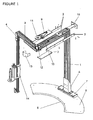
FIGURE 1 is a general view, with some parts in exploded view, of the structure of the machine with some of its elements, showing:- The fixed main arm (1) with an inverted-L shape made from the union of two profiles of a lightweight materials and its reinforcement pieces (2);
- The rotating arm (3) with an inverted-L shape and a smaller size, and its reinforcement pieces (4);
- The C-shaped stand (5) with a guard in its inner part (6) and a raised area (7) in which the scarfed box (8) is attached, where the main arm (1) is housed and attached;
- The motor, transmission and torque limiter group (9) meant to be housed in the space (10) provided in the upper horizontal branch of the main piece, the pulley (11) and the shaft joining the two arms (12) being protected by an additional guard (13);
- The vertical branch of the rotating arm includes the roll-holding carriage (14).
- The outer angle of the main arm houses a support and stabilization piece (15) that will be attached to the wall or another vertical element.
-
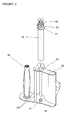
FIGURE 2 is a detailed view of the roll-holding carriage, showing:- A lower laminar piece (16) with means (17) that are inserted in the retaining roller (18) allowing it to turn and the shaft (19) on which the roll of wrapping material will be placed;
- An upper laminar piece (20) with an orifice (32) sufficiently large to allow passing the retaining roller through it (18);
- A plate (21) in which are inserted the shaft of the retaining roller (18), to which a toothed wheel (22) is firmly attached, and the adjustable brake (23);
- Means (24) for joining the upper and lower pieces of the roll-holding carriage.
-
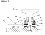
FIGURE 3 is a cross-section of the assembly formed by the adjustable brake (23), the plate (21) and the upper part of the shaft of the retainer roller inserted in the plate (25), showing:- The adjustable brake is essentially constituted by a wheel or knob (26) used to adjust the braking strength, a rotating piece with a different cross-section in each of its segments in which at least its upper part is screwed (27), firmly joined to the wheel and which when it turns displaces either upward or downward a piece (28) that presses or releases a set of springs (29) that in turn transmit the pressure to another lower piece (30) that can be constituted of or incorporate a friction piece which when it moves catches a coaxial rotating piece (31).
- The rotating piece (31) coaxial to the brake engaged to the wheel (22) that turns together with the shaft (25) of the retainer roller.
- A stop (33) to limit the rotation of the screw.
-
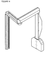
FIGURE 4 shows the protective casing of the machine made of a deformable material that allows absorbing knocks and made from different pieces, all of them joined to the structure of the machine with screws, simplifying the replacement when necessary of any damaged pieces. - A non-limiting example of an embodiment of the invention will be described below.
- For sake of clarity, the description will begin with an example of embodiment of the structure, then an example of embodiment of the roll-holding carriage and finally a detailed description of an embodiment of the assembly consisting of the adjustable brake and its relation to the retaining roller.
- The main structure of the machine consists of two inverted-L shaped arms, one of them fixed and larger in size (1) and the other rotating and slightly smaller (3), the two being connected by a shaft (12) placed on the end of their corresponding horizontal branches.
- These arms are made from profiles of a lightweight material, such as aluminum, all the unions being established by screws.
- To provide sturdiness to the fixed arm, each of its straight segments is composed of two identical profiles, parallel to each other and firmly joined, with the unions, particularly the one at an angle of 90°, being reinforced by additional pieces (2) joined to the structure by screws.
- The structure of the rotating arm (3) consists on its upper part by a central profile and two lateral profiles with a smaller cross-section, one of which is shorter in length that the piece, and the vertical arm constituted by two profiles, one having a greater cross-section and length than the other.
- The unions are established by screws and incorporate reinforcement pieces (4) at certain unions.
- In the horizontal branch of the main arm is a recess (10) in which is housed the motor, which transmits the rotation to the shaft (12) and the rotating arm by means of a belt and a pulley.
- A torque limiter acts on the transmission in such a way that the motor rotation is disengaged from the arm rotation if it encounters a certain resistance to its motion.
- A guard piece (13) is provided to protect the pulley and the end of the main arm.
- The main arm (1) is inserted and fixed in a scarfed box (8) which is in turn fixed to the C-shaped stand (5) at a part in which it is slightly raised (7).
- The inner part of this C-shaped stand (5) has a flange (6) by way of a guard.
- The upper part of the stand has a smooth surface, free of ribs or rods.
- The roll-holding carriage (14) is anchored to the vertical branch of the rotation arm, and moves upward and downward, combining this movement to that of the rotation of the arm to define a helical wrapping.
- The roll-holding carriage (14) is made of a lower laminar piece (16) and an upper laminar piece (20) joined to each other by conventional means (24).
- In the lower laminar piece are established means (17) for coupling to the shaft of the retainer roller (18) as well as the shaft (19) in which the roll or wrapping material is inserted, the latter shaft being free to turn.
- The retainer roller (18) has a surface that adheres to the wrapping material, either by an adhesive, magnetization, friction or any other method.
- The upper laminar piece (20), smaller in size, has a sufficiently large orifice (32) to allow the retaining roller to pass.
- Attached to this upper piece (20) is a plate (21), in which are inserted the end of the shaft of the retainer roller (25) and the circular piece (22) that turns together with it, as well as a brake (23) of adjustable strength, the plate (21) and the brake (23) constituting, together with the piece (22) attached to the shaft of the retainer roller and the retainer roller itself, the group that allows a controlled tension of the wrapping material so that it is tightly wrapped on the bundle.
- The brake (23) is composed of a case in which is housed a series of springs (29), the upper piece (28) and lower piece (30) of this casing being free to move.
- The upper piece (28) moves by the action of a screw (27) that crosses it, this screw being firmly attached to a wheel or knob that can be manipulated to turn the screw (27) and therefore move the upper piece (28).
- The cross-section of this screw changes along its path, in its lower end part having a shape which, when turning, meets against the piece (33) to prevent an excessive tightening of the springs.
- When the upper piece (28) moves to press the springs (29), these move the lower piece (30), which can consist in full or in part by a brake pad, which hinders the rotation of a coaxial turning piece (31) engaged to the rotating piece (22) that is firmly joined to the shaft of the retainer roller.
Claims (13)
- Bundling machine of the type having a main fixed body with an inverted-L shape and an inner rotating arm with an inverted-L shape of a smaller size, these two bodies being joined by a shaft at the end of their corresponding horizontal branches which constitutes the rotation shaft of the smaller inner piece with an inverted-L shape driven by a motor and a gear, wherein said rotating piece incorporates on its vertical branch a roll-holding carriage that contains the roll of the material used to bundle, such as plastic, mesh or fabric, among others, and the tensioning element for the wrapping material, the item to be packed remaining static inside the turning radius of this rotating arm and being wrapped in a helical manner by the combined action of the rotation of said arm and the upward and downward movement of the roll-holding carriage, essentially characterized in that the main body of the machine consists of profiles of different sizes of a lightweight material, such as aluminum, which incorporate reinforcement pieces, guard pieces and kinetic energy absorbing coating elements, in that the bundling machine has a C-shaped stand with a smooth surface traversed by several through orifices, a box being attached to said laminar piece in which is inserted the main body of the machine, in that the support on which the roll of wrapping machine is placed that is on the rotating arm essentially consists of two laminar pieces, an upper and a lower one, and union elements, the upper piece having an orifice large enough to allow passage of the retainer roller, this retainer roller being engaged non-coaxially to a brake with linear and continuous regulation, the support of the brake and roller being a plate that is attached to the carriage by means that allow a simple disassembly.
- Bundling machine essentially characterized in that the structure of the main fixed body, with an inverted-L shape, consists of at least two elongated parts of a profile of a lightweight material, such as aluminum, joined by screws, the union of these profile bodies being reinforced by pieces of a resistant material, incorporating on the end of the horizontal branch of said body a guard made of a resistant material.
- Bundling machine according to the previous claim, essentially characterized in that in an area near the end of the upper horizontal branch there is a recess in which is housed the motor that will move the rotating arm.
- Bundling machine essentially characterized in that the structure of the rotating arm with an inverted-L shape consists of the union of at least to elongated parts of a profile of a lightweight material, such as aluminum, the union point being reinforced by additional pieces of resistant materials.
- Bundling machine essentially characterized in that the stand has a smooth surface and a raised area, said stand having a number of through orifices in which are inserted the bolts that anchor it to the floor.
- Bundling machine as claimed in claim 5 essentially characterized in that the stand is provided on its inner part with a guard consisting of a flange placed on its inner perimeter.
- Bundling machine essentially characterized in that joined to the stand, in an area raised above the rest of the surface, is attached a box that can be scarfed, in which the vertical branch of the main structure of the machine is inserted.
- Bundling machine as claimed in claims 3 and 4 essentially characterized in that the motor located in the horizontal branch of the fixed body is joined through a suitable transmission means, such as a transmission belt, to the shaft that connects the rotation of the motor and the rotating arm, this union being disengaged by the action of a torque limiter if the rotating arm encounters a certain resistance in its path.
- Bundling machine essentially characterized in that the roll-holding carriage is configured by two laminar pieces, an upper and a lower piece, joined by a series of union pieces, wherein the lower piece includes a freely-rotating shaft in which is inserted the roll of packaging material and also means for housing the shaft of the retainer roller, engaged in a non-coaxial manner by its upper part to an adjustable brake, the roller and the brake being inserted in a plate, the upper laminar piece having an orifice that allows the retainer roller to pass.
- Bundling machine according to claim 9 essentially characterized in that the plate, brake and roller form an integral assembly that can be disassembled, and in that said assembly is attached to the upper laminar piece of the frame through the plate by means that allow a simple disassembly, the retainer roller being inserted in the orifice provided in the upper laminar piece.
- Bundling machine essentially characterized in that the means that allow controlling the rotation of the retainer roller are:An adjustable brake consisting of a box or case inside which are house a series of springs in constant contact with an upper closing piece and a lower closing piece, both of which are free to move, wherein the upper closing pieced is crossed and interacts with a screw that is firmly joined at its end to a wheel or knob, such by moving the knob and thereby turning the screw will raise or lower the upper closing piece, increasing or reducing the pressure exerted by it on the springs, which in turn transfer said pressure to the lower closing piece, which will also move to press against or release a rotating piece essentially coaxial to the drum described.A circular piece coaxial to the retainer roller that turns together with it, said piece being engaged to the circular rotating piece coaxial to the brake.The plate referred to in claim 9 that joins all the aforementioned elements.
- Bundling machine as claimed in claim 1 essentially characterized in that it may incorporate means for attachment and stabilization with respect to a vertical or horizontal captive screws and a series of orifices meant to house the attachment screws.
- Bundling machine according to previous claims essentially characterized in that its body is coated by a series of pieces made of a deformable material, such as polyethylene, with a shape allowing to absorb impacts.
Applications Claiming Priority (1)
| Application Number | Priority Date | Filing Date | Title |
|---|---|---|---|
| ES200802243A ES2341209B1 (en) | 2008-07-22 | 2008-07-22 | ENFARDING MACHINE. |
Publications (2)
| Publication Number | Publication Date |
|---|---|
| EP2147864A1 true EP2147864A1 (en) | 2010-01-27 |
| EP2147864B1 EP2147864B1 (en) | 2012-05-16 |
Family
ID=41226327
Family Applications (1)
| Application Number | Title | Priority Date | Filing Date |
|---|---|---|---|
| EP09009403A Active EP2147864B1 (en) | 2008-07-22 | 2009-07-20 | Wrapping device |
Country Status (3)
| Country | Link |
|---|---|
| EP (1) | EP2147864B1 (en) |
| ES (1) | ES2341209B1 (en) |
| PT (1) | PT2147864E (en) |
Cited By (7)
| Publication number | Priority date | Publication date | Assignee | Title |
|---|---|---|---|---|
| DK201370780A1 (en) * | 2013-12-17 | 2015-06-29 | Hovmand As | Device and kit for handling a supply roll of flexible sheet material |
| EP3081526A1 (en) | 2015-04-14 | 2016-10-19 | Aranguren Comercial del Embalaje SL | Transportable wrapper stacker machine |
| EP3835221A2 (en) | 2019-12-13 | 2021-06-16 | Aranguren Comercial del Embalaje SL | Autonomous wrapping machine |
| CN114476249A (en) * | 2022-03-09 | 2022-05-13 | 浙江鼎业机械设备有限公司 | Winding case sealer |
| WO2023152405A2 (en) | 2022-12-13 | 2023-08-17 | Aranguren Comercial del Embalaje, S.L.U. | Procedure and device for film counting and controlling for wrapping machine |
| CN117886138A (en) * | 2024-03-14 | 2024-04-16 | 山西新元自动化仪表有限公司 | A dust suppression bucket that is easy to accurately control |
| WO2024126884A1 (en) | 2022-12-13 | 2024-06-20 | Aranguren Comercial del Embalaje, S.L.U. | Method and device for counting and controlling film for a wrapping machine |
Families Citing this family (5)
| Publication number | Priority date | Publication date | Assignee | Title |
|---|---|---|---|---|
| ES1077170Y (en) | 2012-05-14 | 2012-09-07 | Aranguren Com Del Embalaje S L | FILM ELECTRIC CUTTING AND WELDING MODULAR DEVICE FOR COOLING MACHINES |
| CN109911278B (en) * | 2019-04-10 | 2024-01-16 | 北京印刷学院 | Mobilizable portable twines membrane machine |
| ES1260337Y (en) | 2020-11-20 | 2021-04-30 | Aranguren Com Del Embalaje S L U | CUTTING AND WELDING DEVICE FOR A BALER |
| ES1270355Y (en) | 2021-03-11 | 2021-09-29 | Aranguren Com Del Embalaje S L U | FILM PRE-EXTRACTING AND BRAKING DEVICE FOR REEL CARRIAGE ON A BALER |
| ES1290845Y (en) | 2022-03-24 | 2022-08-24 | Aranguren Com Del Embalaje S L U | STRUCTURE FOR WRAPPING MACHINE |
Citations (16)
| Publication number | Priority date | Publication date | Assignee | Title |
|---|---|---|---|---|
| US4282700A (en) | 1979-04-12 | 1981-08-11 | Joseph Goldstein | Stretch wrapper for palletized load |
| ES522381A0 (en) | 1983-05-13 | 1984-05-01 | Carnes Y Conservas Espanolas S | PALLET BANDING MACHINE. |
| ES285252U (en) | 1985-02-25 | 1986-03-01 | Serpack, S.A. | Self-regulating supplier for packing band, in a boiler (Machine-translation by Google Translate, not legally binding) |
| ES2000877A6 (en) | 1986-08-22 | 1988-03-16 | Dow Chemical Co | Mono:- or di:chloro-tri:fluoromethyl -pyridine cpds. prepn. |
| ES2001227A6 (en) | 1986-07-08 | 1988-05-01 | Serpack Sa | Filler with apparatus to stretch a packing band (Machine-translation by Google Translate, not legally binding) |
| FR2608140A3 (en) | 1986-12-09 | 1988-06-17 | Deome Plastiques | Braked manual pay-out support for a reel of stretchable film |
| US4914891A (en) * | 1987-05-27 | 1990-04-10 | Oy M. Haloila Ab | Method and apparatus for exchanging film rolls in a wrapping machine |
| WO1990006261A1 (en) * | 1988-11-25 | 1990-06-14 | Newtec International | Mobile film dispenser carrying device for a packaging machine |
| ES1013952U (en) * | 1990-05-18 | 1991-02-01 | Serpack, S.A. | Baler rotating arm. (Machine-translation by Google Translate, not legally binding) |
| ES2113244A2 (en) | 1993-12-16 | 1998-04-16 | Mar Srl | Machine for wrapping packages with film extensible film. (Machine-translation by Google Translate, not legally binding) |
| EP1300339A1 (en) | 2001-09-24 | 2003-04-09 | Heikaus Vertriebs-GmbH | Wrapping apparatus |
| DE10220803A1 (en) | 2002-05-10 | 2003-12-24 | Heikaus Unternehmensbeteiligun | Procedure for wrapping of objects on pallet with film sheet entails unwinding film from roll which during producing of lower film layer is guided so that lower layer at least partially overlaps pallet |
| EP1522494A1 (en) | 2002-10-01 | 2005-04-13 | Illinois Tool Works Inc. | Apparatus for wrapping and braking a film |
| EP1690792A1 (en) * | 2005-02-09 | 2006-08-16 | Lorenzo Pozzato | Assisted-delivery, pre-stretching unit for a pallet-wrapping apparatus |
| EP1733967A1 (en) * | 2005-06-17 | 2006-12-20 | E.R.I.M. Sarl | Device for wrapping products on a pallet |
| ES2271738T3 (en) | 2003-06-16 | 2007-04-16 | Illinois Tool Works Inc. | DEVELOPMENT DEVICE. |
Family Cites Families (4)
| Publication number | Priority date | Publication date | Assignee | Title |
|---|---|---|---|---|
| US6293074B1 (en) * | 1998-02-20 | 2001-09-25 | Lantech Management Corp. | Method and apparatus for stretch wrapping a load |
| IT1319650B1 (en) * | 2000-11-14 | 2003-10-23 | Sestese Off Mec | UNWINDING REEL EQUIPPED WITH DRIVING DEACTIVATION VEHICLES. |
| US6539690B2 (en) * | 2001-06-27 | 2003-04-01 | Illinois Tool Works Inc. | Semi-automatic film cut/clamp device and method of operating the same |
| ITBO20050258A1 (en) * | 2005-04-19 | 2006-10-20 | Noxon S R L | WRAPPING MACHINE |
-
2008
- 2008-07-22 ES ES200802243A patent/ES2341209B1/en active Active
-
2009
- 2009-07-20 PT PT09009403T patent/PT2147864E/en unknown
- 2009-07-20 EP EP09009403A patent/EP2147864B1/en active Active
Patent Citations (17)
| Publication number | Priority date | Publication date | Assignee | Title |
|---|---|---|---|---|
| US4282700A (en) | 1979-04-12 | 1981-08-11 | Joseph Goldstein | Stretch wrapper for palletized load |
| ES522381A0 (en) | 1983-05-13 | 1984-05-01 | Carnes Y Conservas Espanolas S | PALLET BANDING MACHINE. |
| ES285252U (en) | 1985-02-25 | 1986-03-01 | Serpack, S.A. | Self-regulating supplier for packing band, in a boiler (Machine-translation by Google Translate, not legally binding) |
| ES2001227A6 (en) | 1986-07-08 | 1988-05-01 | Serpack Sa | Filler with apparatus to stretch a packing band (Machine-translation by Google Translate, not legally binding) |
| ES2000877A6 (en) | 1986-08-22 | 1988-03-16 | Dow Chemical Co | Mono:- or di:chloro-tri:fluoromethyl -pyridine cpds. prepn. |
| FR2608140A3 (en) | 1986-12-09 | 1988-06-17 | Deome Plastiques | Braked manual pay-out support for a reel of stretchable film |
| US4914891A (en) * | 1987-05-27 | 1990-04-10 | Oy M. Haloila Ab | Method and apparatus for exchanging film rolls in a wrapping machine |
| FI81539B (en) | 1988-11-25 | 1990-07-31 | Newtec Int | FILMDELNINGSKAELKE FOER EN VECKLINGSMASKIN. |
| WO1990006261A1 (en) * | 1988-11-25 | 1990-06-14 | Newtec International | Mobile film dispenser carrying device for a packaging machine |
| ES1013952U (en) * | 1990-05-18 | 1991-02-01 | Serpack, S.A. | Baler rotating arm. (Machine-translation by Google Translate, not legally binding) |
| ES2113244A2 (en) | 1993-12-16 | 1998-04-16 | Mar Srl | Machine for wrapping packages with film extensible film. (Machine-translation by Google Translate, not legally binding) |
| EP1300339A1 (en) | 2001-09-24 | 2003-04-09 | Heikaus Vertriebs-GmbH | Wrapping apparatus |
| DE10220803A1 (en) | 2002-05-10 | 2003-12-24 | Heikaus Unternehmensbeteiligun | Procedure for wrapping of objects on pallet with film sheet entails unwinding film from roll which during producing of lower film layer is guided so that lower layer at least partially overlaps pallet |
| EP1522494A1 (en) | 2002-10-01 | 2005-04-13 | Illinois Tool Works Inc. | Apparatus for wrapping and braking a film |
| ES2271738T3 (en) | 2003-06-16 | 2007-04-16 | Illinois Tool Works Inc. | DEVELOPMENT DEVICE. |
| EP1690792A1 (en) * | 2005-02-09 | 2006-08-16 | Lorenzo Pozzato | Assisted-delivery, pre-stretching unit for a pallet-wrapping apparatus |
| EP1733967A1 (en) * | 2005-06-17 | 2006-12-20 | E.R.I.M. Sarl | Device for wrapping products on a pallet |
Cited By (10)
| Publication number | Priority date | Publication date | Assignee | Title |
|---|---|---|---|---|
| DK201370780A1 (en) * | 2013-12-17 | 2015-06-29 | Hovmand As | Device and kit for handling a supply roll of flexible sheet material |
| EP3081526A1 (en) | 2015-04-14 | 2016-10-19 | Aranguren Comercial del Embalaje SL | Transportable wrapper stacker machine |
| EP3835221A2 (en) | 2019-12-13 | 2021-06-16 | Aranguren Comercial del Embalaje SL | Autonomous wrapping machine |
| CN114476249A (en) * | 2022-03-09 | 2022-05-13 | 浙江鼎业机械设备有限公司 | Winding case sealer |
| CN114476249B (en) * | 2022-03-09 | 2023-07-04 | 浙江鼎业机械设备有限公司 | Winding case sealer |
| WO2023152405A2 (en) | 2022-12-13 | 2023-08-17 | Aranguren Comercial del Embalaje, S.L.U. | Procedure and device for film counting and controlling for wrapping machine |
| WO2024126884A1 (en) | 2022-12-13 | 2024-06-20 | Aranguren Comercial del Embalaje, S.L.U. | Method and device for counting and controlling film for a wrapping machine |
| EP4635861A1 (en) | 2022-12-13 | 2025-10-22 | Aranguren Comercial del Embalaje, S.L.U. | Method and device for counting and controlling film for a wrapping machine |
| CN117886138A (en) * | 2024-03-14 | 2024-04-16 | 山西新元自动化仪表有限公司 | A dust suppression bucket that is easy to accurately control |
| CN117886138B (en) * | 2024-03-14 | 2024-05-28 | 山西新元自动化仪表有限公司 | A dust suppression bucket that is easy to accurately control |
Also Published As
| Publication number | Publication date |
|---|---|
| EP2147864B1 (en) | 2012-05-16 |
| ES2341209A1 (en) | 2010-06-16 |
| ES2341209B1 (en) | 2011-05-11 |
| PT2147864E (en) | 2012-07-25 |
Similar Documents
| Publication | Publication Date | Title |
|---|---|---|
| EP2147864B1 (en) | Wrapping device | |
| CN107719735B (en) | Multifunctional bundling machine | |
| CN201895719U (en) | Road building machinery and crawler belt transmission unit | |
| CN201566850U (en) | Dual purpose stretch wrapping machine | |
| CN202911132U (en) | Film flattening device under tension control | |
| US8888033B2 (en) | Spring-driven reel | |
| ITMI962394A1 (en) | EPICYCLOIDAL BAND PACKER | |
| US9440757B2 (en) | Process for forming and filling a pouch on a VFFS machine | |
| CN107984295A (en) | A kind of lathe protective device | |
| CN106184903A (en) | A kind of full-automatic binding machine for many specifications express box and method of work | |
| CN111204610B (en) | Large-caliber polarization wire grating winding device | |
| SI22800A (en) | Hydraulic driving and guiding assembly of a line supporting element, in particularly pulley of a forestry winch | |
| CN201584292U (en) | Tensioning device for coil winding | |
| CN108181935A (en) | A kind of single shaft sun tracker | |
| AU2013330217A1 (en) | Level winder | |
| CN214767929U (en) | Steel coil feeding and uncoiling device | |
| CN207433884U (en) | A kind of Multifunctional strapping machine | |
| CN102390582B (en) | Unpacking and feeding machine | |
| CN203111542U (en) | Plastic steel belt strapping machine belt strapping plate device | |
| CN201890366U (en) | Jelly product packaging and feeding machine | |
| CN207973138U (en) | A kind of light belt conveyer | |
| KR20160018100A (en) | Transmission tower | |
| KR101006628B1 (en) | Electric conveying device using wire rope | |
| KR20140066870A (en) | Power sprayer and winder drum for medicine supply hose | |
| CN212891141U (en) | Device is hugged closely to coiled material packaging material |
Legal Events
| Date | Code | Title | Description |
|---|---|---|---|
| PUAI | Public reference made under article 153(3) epc to a published international application that has entered the european phase |
Free format text: ORIGINAL CODE: 0009012 |
|
| AK | Designated contracting states |
Kind code of ref document: A1 Designated state(s): AT BE BG CH CY CZ DE DK EE ES FI FR GB GR HR HU IE IS IT LI LT LU LV MC MK MT NL NO PL PT RO SE SI SK SM TR |
|
| AX | Request for extension of the european patent |
Extension state: AL BA RS |
|
| 17P | Request for examination filed |
Effective date: 20100726 |
|
| 17Q | First examination report despatched |
Effective date: 20110119 |
|
| GRAP | Despatch of communication of intention to grant a patent |
Free format text: ORIGINAL CODE: EPIDOSNIGR1 |
|
| RTI1 | Title (correction) |
Free format text: WRAPPING DEVICE |
|
| GRAS | Grant fee paid |
Free format text: ORIGINAL CODE: EPIDOSNIGR3 |
|
| GRAA | (expected) grant |
Free format text: ORIGINAL CODE: 0009210 |
|
| AK | Designated contracting states |
Kind code of ref document: B1 Designated state(s): AT BE BG CH CY CZ DE DK EE ES FI FR GB GR HR HU IE IS IT LI LT LU LV MC MK MT NL NO PL PT RO SE SI SK SM TR |
|
| REG | Reference to a national code |
Ref country code: GB Ref legal event code: FG4D |
|
| REG | Reference to a national code |
Ref country code: CH Ref legal event code: EP |
|
| REG | Reference to a national code |
Ref country code: AT Ref legal event code: REF Ref document number: 557971 Country of ref document: AT Kind code of ref document: T Effective date: 20120615 |
|
| REG | Reference to a national code |
Ref country code: IE Ref legal event code: FG4D |
|
| REG | Reference to a national code |
Ref country code: DE Ref legal event code: R096 Ref document number: 602009006923 Country of ref document: DE Effective date: 20120719 |
|
| REG | Reference to a national code |
Ref country code: PT Ref legal event code: SC4A Free format text: AVAILABILITY OF NATIONAL TRANSLATION Effective date: 20120718 |
|
| REG | Reference to a national code |
Ref country code: NL Ref legal event code: VDEP Effective date: 20120516 |
|
| REG | Reference to a national code |
Ref country code: LT Ref legal event code: MG4D Effective date: 20120516 |
|
| PG25 | Lapsed in a contracting state [announced via postgrant information from national office to epo] |
Ref country code: SE Free format text: LAPSE BECAUSE OF FAILURE TO SUBMIT A TRANSLATION OF THE DESCRIPTION OR TO PAY THE FEE WITHIN THE PRESCRIBED TIME-LIMIT Effective date: 20120516 Ref country code: IS Free format text: LAPSE BECAUSE OF FAILURE TO SUBMIT A TRANSLATION OF THE DESCRIPTION OR TO PAY THE FEE WITHIN THE PRESCRIBED TIME-LIMIT Effective date: 20120916 Ref country code: PL Free format text: LAPSE BECAUSE OF FAILURE TO SUBMIT A TRANSLATION OF THE DESCRIPTION OR TO PAY THE FEE WITHIN THE PRESCRIBED TIME-LIMIT Effective date: 20120516 Ref country code: LT Free format text: LAPSE BECAUSE OF FAILURE TO SUBMIT A TRANSLATION OF THE DESCRIPTION OR TO PAY THE FEE WITHIN THE PRESCRIBED TIME-LIMIT Effective date: 20120516 Ref country code: FI Free format text: LAPSE BECAUSE OF FAILURE TO SUBMIT A TRANSLATION OF THE DESCRIPTION OR TO PAY THE FEE WITHIN THE PRESCRIBED TIME-LIMIT Effective date: 20120516 Ref country code: CY Free format text: LAPSE BECAUSE OF FAILURE TO SUBMIT A TRANSLATION OF THE DESCRIPTION OR TO PAY THE FEE WITHIN THE PRESCRIBED TIME-LIMIT Effective date: 20120516 Ref country code: NO Free format text: LAPSE BECAUSE OF FAILURE TO SUBMIT A TRANSLATION OF THE DESCRIPTION OR TO PAY THE FEE WITHIN THE PRESCRIBED TIME-LIMIT Effective date: 20120816 |
|
| REG | Reference to a national code |
Ref country code: AT Ref legal event code: MK05 Ref document number: 557971 Country of ref document: AT Kind code of ref document: T Effective date: 20120516 |
|
| PG25 | Lapsed in a contracting state [announced via postgrant information from national office to epo] |
Ref country code: LV Free format text: LAPSE BECAUSE OF FAILURE TO SUBMIT A TRANSLATION OF THE DESCRIPTION OR TO PAY THE FEE WITHIN THE PRESCRIBED TIME-LIMIT Effective date: 20120516 Ref country code: GR Free format text: LAPSE BECAUSE OF FAILURE TO SUBMIT A TRANSLATION OF THE DESCRIPTION OR TO PAY THE FEE WITHIN THE PRESCRIBED TIME-LIMIT Effective date: 20120817 Ref country code: HR Free format text: LAPSE BECAUSE OF FAILURE TO SUBMIT A TRANSLATION OF THE DESCRIPTION OR TO PAY THE FEE WITHIN THE PRESCRIBED TIME-LIMIT Effective date: 20120516 Ref country code: SI Free format text: LAPSE BECAUSE OF FAILURE TO SUBMIT A TRANSLATION OF THE DESCRIPTION OR TO PAY THE FEE WITHIN THE PRESCRIBED TIME-LIMIT Effective date: 20120516 |
|
| PG25 | Lapsed in a contracting state [announced via postgrant information from national office to epo] |
Ref country code: BE Free format text: LAPSE BECAUSE OF FAILURE TO SUBMIT A TRANSLATION OF THE DESCRIPTION OR TO PAY THE FEE WITHIN THE PRESCRIBED TIME-LIMIT Effective date: 20120516 |
|
| PG25 | Lapsed in a contracting state [announced via postgrant information from national office to epo] |
Ref country code: DK Free format text: LAPSE BECAUSE OF FAILURE TO SUBMIT A TRANSLATION OF THE DESCRIPTION OR TO PAY THE FEE WITHIN THE PRESCRIBED TIME-LIMIT Effective date: 20120516 Ref country code: RO Free format text: LAPSE BECAUSE OF FAILURE TO SUBMIT A TRANSLATION OF THE DESCRIPTION OR TO PAY THE FEE WITHIN THE PRESCRIBED TIME-LIMIT Effective date: 20120516 Ref country code: EE Free format text: LAPSE BECAUSE OF FAILURE TO SUBMIT A TRANSLATION OF THE DESCRIPTION OR TO PAY THE FEE WITHIN THE PRESCRIBED TIME-LIMIT Effective date: 20120516 Ref country code: CZ Free format text: LAPSE BECAUSE OF FAILURE TO SUBMIT A TRANSLATION OF THE DESCRIPTION OR TO PAY THE FEE WITHIN THE PRESCRIBED TIME-LIMIT Effective date: 20120516 Ref country code: NL Free format text: LAPSE BECAUSE OF FAILURE TO SUBMIT A TRANSLATION OF THE DESCRIPTION OR TO PAY THE FEE WITHIN THE PRESCRIBED TIME-LIMIT Effective date: 20120516 Ref country code: AT Free format text: LAPSE BECAUSE OF FAILURE TO SUBMIT A TRANSLATION OF THE DESCRIPTION OR TO PAY THE FEE WITHIN THE PRESCRIBED TIME-LIMIT Effective date: 20120516 Ref country code: SK Free format text: LAPSE BECAUSE OF FAILURE TO SUBMIT A TRANSLATION OF THE DESCRIPTION OR TO PAY THE FEE WITHIN THE PRESCRIBED TIME-LIMIT Effective date: 20120516 |
|
| PG25 | Lapsed in a contracting state [announced via postgrant information from national office to epo] |
Ref country code: MC Free format text: LAPSE BECAUSE OF NON-PAYMENT OF DUE FEES Effective date: 20120731 Ref country code: MK Free format text: LAPSE BECAUSE OF FAILURE TO SUBMIT A TRANSLATION OF THE DESCRIPTION OR TO PAY THE FEE WITHIN THE PRESCRIBED TIME-LIMIT Effective date: 20120516 |
|
| PLBE | No opposition filed within time limit |
Free format text: ORIGINAL CODE: 0009261 |
|
| STAA | Information on the status of an ep patent application or granted ep patent |
Free format text: STATUS: NO OPPOSITION FILED WITHIN TIME LIMIT |
|
| 26N | No opposition filed |
Effective date: 20130219 |
|
| PG25 | Lapsed in a contracting state [announced via postgrant information from national office to epo] |
Ref country code: ES Free format text: LAPSE BECAUSE OF FAILURE TO SUBMIT A TRANSLATION OF THE DESCRIPTION OR TO PAY THE FEE WITHIN THE PRESCRIBED TIME-LIMIT Effective date: 20120827 |
|
| REG | Reference to a national code |
Ref country code: IE Ref legal event code: MM4A |
|
| REG | Reference to a national code |
Ref country code: DE Ref legal event code: R097 Ref document number: 602009006923 Country of ref document: DE Effective date: 20130219 |
|
| PG25 | Lapsed in a contracting state [announced via postgrant information from national office to epo] |
Ref country code: MT Free format text: LAPSE BECAUSE OF FAILURE TO SUBMIT A TRANSLATION OF THE DESCRIPTION OR TO PAY THE FEE WITHIN THE PRESCRIBED TIME-LIMIT Effective date: 20120516 Ref country code: IE Free format text: LAPSE BECAUSE OF NON-PAYMENT OF DUE FEES Effective date: 20120720 Ref country code: BG Free format text: LAPSE BECAUSE OF FAILURE TO SUBMIT A TRANSLATION OF THE DESCRIPTION OR TO PAY THE FEE WITHIN THE PRESCRIBED TIME-LIMIT Effective date: 20120816 |
|
| REG | Reference to a national code |
Ref country code: CH Ref legal event code: PL |
|
| PG25 | Lapsed in a contracting state [announced via postgrant information from national office to epo] |
Ref country code: LI Free format text: LAPSE BECAUSE OF NON-PAYMENT OF DUE FEES Effective date: 20130731 Ref country code: TR Free format text: LAPSE BECAUSE OF FAILURE TO SUBMIT A TRANSLATION OF THE DESCRIPTION OR TO PAY THE FEE WITHIN THE PRESCRIBED TIME-LIMIT Effective date: 20120516 Ref country code: CH Free format text: LAPSE BECAUSE OF NON-PAYMENT OF DUE FEES Effective date: 20130731 |
|
| PG25 | Lapsed in a contracting state [announced via postgrant information from national office to epo] |
Ref country code: LU Free format text: LAPSE BECAUSE OF NON-PAYMENT OF DUE FEES Effective date: 20120720 Ref country code: SM Free format text: LAPSE BECAUSE OF FAILURE TO SUBMIT A TRANSLATION OF THE DESCRIPTION OR TO PAY THE FEE WITHIN THE PRESCRIBED TIME-LIMIT Effective date: 20120516 |
|
| PG25 | Lapsed in a contracting state [announced via postgrant information from national office to epo] |
Ref country code: HU Free format text: LAPSE BECAUSE OF FAILURE TO SUBMIT A TRANSLATION OF THE DESCRIPTION OR TO PAY THE FEE WITHIN THE PRESCRIBED TIME-LIMIT Effective date: 20090720 |
|
| REG | Reference to a national code |
Ref country code: FR Ref legal event code: PLFP Year of fee payment: 8 |
|
| REG | Reference to a national code |
Ref country code: FR Ref legal event code: PLFP Year of fee payment: 9 |
|
| REG | Reference to a national code |
Ref country code: FR Ref legal event code: PLFP Year of fee payment: 10 |
|
| P01 | Opt-out of the competence of the unified patent court (upc) registered |
Free format text: CASE NUMBER: APP_20764/2025 Effective date: 20250430 |
|
| PGFP | Annual fee paid to national office [announced via postgrant information from national office to epo] |
Ref country code: PT Payment date: 20250721 Year of fee payment: 17 |
|
| PGFP | Annual fee paid to national office [announced via postgrant information from national office to epo] |
Ref country code: DE Payment date: 20250710 Year of fee payment: 17 |
|
| PGFP | Annual fee paid to national office [announced via postgrant information from national office to epo] |
Ref country code: IT Payment date: 20250721 Year of fee payment: 17 |
|
| PGFP | Annual fee paid to national office [announced via postgrant information from national office to epo] |
Ref country code: GB Payment date: 20250710 Year of fee payment: 17 |
|
| PGFP | Annual fee paid to national office [announced via postgrant information from national office to epo] |
Ref country code: FR Payment date: 20250711 Year of fee payment: 17 |