EP1300339A1 - Wrapping apparatus - Google Patents
Wrapping apparatus Download PDFInfo
- Publication number
- EP1300339A1 EP1300339A1 EP02021144A EP02021144A EP1300339A1 EP 1300339 A1 EP1300339 A1 EP 1300339A1 EP 02021144 A EP02021144 A EP 02021144A EP 02021144 A EP02021144 A EP 02021144A EP 1300339 A1 EP1300339 A1 EP 1300339A1
- Authority
- EP
- European Patent Office
- Prior art keywords
- holder
- roll
- winding
- film
- roll holder
- Prior art date
- Legal status (The legal status is an assumption and is not a legal conclusion. Google has not performed a legal analysis and makes no representation as to the accuracy of the status listed.)
- Withdrawn
Links
Images

Classifications
-
- B—PERFORMING OPERATIONS; TRANSPORTING
- B65—CONVEYING; PACKING; STORING; HANDLING THIN OR FILAMENTARY MATERIAL
- B65B—MACHINES, APPARATUS OR DEVICES FOR, OR METHODS OF, PACKAGING ARTICLES OR MATERIALS; UNPACKING
- B65B11/00—Wrapping, e.g. partially or wholly enclosing, articles or quantities of material, in strips, sheets or blanks, of flexible material
- B65B11/04—Wrapping, e.g. partially or wholly enclosing, articles or quantities of material, in strips, sheets or blanks, of flexible material the articles being rotated
- B65B11/045—Wrapping, e.g. partially or wholly enclosing, articles or quantities of material, in strips, sheets or blanks, of flexible material the articles being rotated by rotating platforms supporting the articles
-
- B—PERFORMING OPERATIONS; TRANSPORTING
- B65—CONVEYING; PACKING; STORING; HANDLING THIN OR FILAMENTARY MATERIAL
- B65B—MACHINES, APPARATUS OR DEVICES FOR, OR METHODS OF, PACKAGING ARTICLES OR MATERIALS; UNPACKING
- B65B11/00—Wrapping, e.g. partially or wholly enclosing, articles or quantities of material, in strips, sheets or blanks, of flexible material
- B65B2011/002—Prestretching mechanism in wrapping machines
Definitions
- the invention relates to a winding device for wrapping objects.
- winding devices for wrapping on Objects arranged on pallets with foils, in particular stretch foils used.
- the items on the. are like cardboard boxes with a thin plastic film Pallet fixed for transport, for example.
- the film used to increase the Packaging security can also be pre-stretched, has essentially that Task that the objects on the pallet are held securely.
- the slide that usually wound as a 40 to 60 cm wide film tape on a roll is often wrapped around the pallet by hand.
- winding devices such as pallet wrapping machines
- a receiving device for receiving the to be wrapped with boxes or the like have loaded pallets.
- the receiving device is for example, around a turntable on which the pallet is placed and around hers own axis can be rotated.
- Such devices also have a Roll holder to hold the film roll.
- To wrap the for example, objects stacked on a pallet will be the beginning of the slide connected to the pallet and by rotating the pick-up device, i.e. by rotating the pallet, the film is unwound from the film roll and simultaneous wrapping of the objects on the pallet.
- winding devices have a vertical displacement device that carries the roll holder. Through the vertical shifting device becomes the film roll while wrapping the object vertically shifted. This is necessary, for example, on the to wrap stacked objects over their entire height and to keep it safe on the pallet.
- the roll holder In known winding devices, the roll holder is freely accessible attached to a vertical strut, the vertical strut the vertical displacement device wearing. Since the roll holder is freely accessible, Avoiding injuries ensure that the wrapping process is automatic is interrupted. To do this, for example, are below the vertical slidable roll holder pressure plates or other sensors provided, or the like when touched by a foot. cancel the wrapping process. This ensures, for example, that when shutting down the Roller holder in the down position not an operator's foot from the Roll holder is injured.
- Known winding devices also have the Disadvantage that the roll holder and the vertical displacement device easily contaminate and are therefore prone to failure.
- the object of the invention is to provide a winding device, in particular for Wrapping objects arranged on pallets is also suitable create in which the risk of injury is reduced in a simple manner.
- the winding device has a receiving device as well a roll holder, wherein for wrapping the object or objects that are preferably arranged on a pallet, the receiving device rotated and / or the roller holder around the object or objects is led around. Both by moving the film roll around the Object around as well as by rotating the object itself Wrapping and in most applications, fixing the objects on the pallet. Furthermore, there is a vertical displacement device, which Roller holder carries, provided. According to the invention, the vertical displacement device and the roll holder during the winding process arranged in a closed housing. The roll holder is thus during the entire winding process, i.e. during the vertical Displacement with the help of the vertical displacement device from a housing surround. From the housing is only the film, for example by an im Slit running essentially over the entire height of the housing, led out. There is no risk of injury to the film itself as this for example, if a hand gets between the film and the object, tears very easily.
- the roll holder for changing the film roll preferably movable out of the housing into an exchange position.
- the roll holder In this replacement position, the roll holder is easily accessible, so that the Role can be changed easily. This avoids that the housing has large voids.
- has a movable Roll holder has the advantage that the roll, for example, from a roll load-bearing mandrel can be pulled off, since the roller holder at least partially in their replacement position at a distance from the Housing is in which the film roll simply upwards from the mandrel can be pulled down or attached to it from above.
- the roller holder is preferably pivotable with the vertical sliding holder connected so that the roll holder from a The winding position can be swiveled into or out of the Exchange position can be pivoted back into the winding position.
- the roll holder is pivoted here, for example, by one vertical axis.
- the roll holder or the roll holder supporting element preferably a holding or locking element to the To be able to fix the roll holder in the winding and / or replacement position.
- the roll holder is one horizontal axis swiveling.
- the horizontal axis is preferred related to one in the winding tower or the like.
- vertically arranged roll holder provided the lower end.
- the Roll holder In an exchange position, the Roll holder preferably at an angle of 30 ° to a vertical up to 60 °.
- the like can be used as a mandrel.
- formed Roll holder the film roll can be easily attached from above.
- the roll holder or an element that carries the roll holder is again preferably provided with a holding or fixing element through which the Roll holder can be fixed in the winding and / or replacement position. Since in this embodiment the roll holder is folded into the winding position a stop in the replacement position is also sufficient provided.
- the roll holder is between the The winding position and the exchange position can be shifted with the vertical shifting device connected.
- the vertical shifting device for example, telescopic rails provided in order to be able to pull the roll holder out of the housing, to put them in the exchange position.
- the exchange position is preferably at working height arranged.
- the roll holder is thus for changing the Foil roll not in its lowest position.
- the roll holder is located rather when replacing the film roll in an ergonomically favorable position.
- the vertical displacement device has a particularly preferred Embodiment on a platen.
- On the platen lies in the Mainly the weight of the film roll on while it is in the Winding position, i.e. is vertically displaceable.
- the Roll holder on a support or support plate for example, when swung in or inserted roller holder rests on the support plate.
- This has the advantage that the position of the roll in the winding position is clear is defined and the weight of the film roll is carried by a support plate can be, which can be correspondingly massive.
- the weight of the Film roll therefore does not have to be continuously by one, for example swiveling arm or the telescopic rails can be carried.
- the roller holder is preferably also connected to a deflection roller which is movable together with the roller holder in the exchange position.
- the Deflection roller serves to deflect the film so that the film is in the winding position the roll holder, for example through a slot or other opening can be led out of the housing or the like without housing edges. to touch and get damaged.
- the guide roller is movable together with the roller holder in the exchange position and preferably firmly connected to the roll holder, it is very easy to Foil before moving the roll holder from the replacement position to the Place the winding position around the pulley and then the roll holder to move back to its winding position. Moving the film around one in the deflection roller arranged in the housing or in the winding position is considerable more difficult and therefore more time consuming.
- the deflection roller preferably lies against a pressure roller in the winding position, so that the film is guided between the deflection roller and the pressure roller. There the deflection roller can be moved into the exchange position together with the roller holder is and in this position already moving the film around the Deflection roller takes place when the roller holder is moved back into the Winding position automatically pressing the film between the guide roller and the pressure roller.
- the location of the film is clearly fixed in the housing of the winding device. Furthermore, for example, by varying the pressing force, a tension in the film be generated.
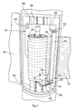
- a winding device for wrapping around a pallet 10, for example arranged objects 12, such as stacked one above the other Cartons, has a receiving device 14 on which the pallet 10th is arranged.
- the receiving device 14 is a turntable, which is about an axis 16 is rotatable.
- the winding device has a winding tower 18, within which a film roll is held 24 and in the direction of an arrow 20 vertically is movable.
- a film 22 is unwound from the film roll 24 and the pallet 10 wrapped together with the cartons 12.
- By slowly moving the Film roll in the direction of arrow 20 is wrapped around the cartons 12 the entire height.
- a height sensor is usually provided, through which the Height of the objects stacked on the pallet 10 is perceived, so that the vertical movement of the film roll is automatically stopped.
- a sensor can be provided that emits light and sensor receives light reflected from the objects 12.
- a roll holder 26 (FIG. 2) is used to hold a film roll 24. intended. 2, the roller holder 26 is in an exchange position shown. In the exchange position, the roller holder 26 is made of one Housing 28 of the winding tower 18 in the illustrated embodiment folded out or swiveled. This can be done ergonomically Favorable working height arranged door 30 of the housing to be opened to pivot the roll holder into the shown replacement position.
- the roller holder 26 In a winding position, the roller holder 26 is in the housing 28 pivoted so that the door 30 can be closed again.
- the Roll bracket 26 is then inside the housing over the entire height of the winding tower 18 vertically by means of a vertical displacement device 32 (FIG. 3) postponed.
- the film 22 is essentially covered by the entire height of the winding tower 18 or the housing 28 extending slot 34 out of the housing in the direction of the receiving device 14.
- the film roll 24 is placed on a mandrel 36 of the roll holder 26.
- the film roll 24 can easily Pulled upwards from the mandrel 36 or plugged onto the mandrel 36 become.
- the roller holder in the exchange position moved out of the housing 28, for example is swung out or pulled out.
- the roller holder 26 a carrier plate 38 connected to the mandrel.
- the mandrel 36 is here preferably rotatably connected to the carrier plate 38.
- the carrier plate 38 can about a pivot axis 40 in the exchange position (Fig. 2) or Winding position (Fig. 3) are pivoted.
- the pivot axis 40 is with a Support plate 42 of the vertical displacement device 32 connected.
- the winding position is the carrier plate 38 of the roller holder 26 on the Support plate 42 of the vertical displacement device 32, so that the support plate 42 essentially carries the weight of the film roll.
- This has the advantage that the pivot axis 40 can be made relatively thin.
- the roller holder 26 also has a deflection roller 44.
- the pulley 44 serves that the film 22 of the film roll 24 in the winding position by the Slot 34 is guided out of the housing 28 without the edges of the Slot 34 are touched. This will damage the film 22 when Avoid wrapping the objects 12.
- the deflection roller 44 is also present a pressure roller 46 connected to the vertical displacement device 32, so that the film 22 between the deflection roller 44 and the pressure roller 46 runs. For example, by setting a contact pressure between the The two rollers 44, 46 can adjust the tension of the film and, if necessary, at The objects 12 are wrapped and the film is stretched or stretched. For this purpose it is also known, preferably in the case of one of the two rollers 44, 46 the pressure roller 46 to provide a brake to determine the amount of extension of the To be able to adjust film 22 during the winding process.
- the deflection roller 44 is on an L-shaped bracket 48, which with the vertical displacement device 32 is connected via a pin 50 in a slot held.
- the opposite end of the deflection roller 44 has an arm 52 connected and rotatably mounted on this.
- the arm 52 is at a distance too the carrier plate 38 arranged and fastened to a bolt 54.
- a spring is provided through which the Deflection roller 44 is pressed against the pressure roller 46.
- the pin 50 must be removed from the the holder 48 connected to the vertical displacement device 32 can be released. Since the holder 52 is at a distance from the carrier plate 38, the Deflection roller 44 can be tilted slightly. By pivoting the pin 50 can loosened the slot and then the roller holder 26 into that shown in Fig. 2 Exchange position can be pivoted.
- the roller holder has a lock or a locking pin 58.
- the locking pin 58 can for example be pulled up against a spring and snaps into a recess in the support plate 42 in the winding position on.
- the vertical displacement device 32 has a vertically arranged one Base plate 60 on which the bracket 48 and the support plate 42, is fastened, for example, by welding.
- the base plate is inside the Housing 28, i.e. a cavity located within the housing vertically in the direction of arrow 20 (Fig. 1), the base plate with four rollers 62 are connected which guide the base plate along Ensure guide rails 64.
- a chain 66 connected to a motor, one of the two chain strands are firmly connected to the base plate 60.
- the vertical displacement device 32 and the roll holder 26 arranged and vertical is displaceable, also all other control and drive units of the Winding device provided.
- the drive and / or the control for driving the Receiving device 14 can be arranged in the winding tower 18. All required units of the winding device are thus in a slim, provided a winding tower requiring little space.
Abstract
Description
Die Erfindung betrifft eine Wickelvorrichtung zum Umwickeln von Gegenständen. Insbesondere werden derartige Wickelvorrichtungen zum Umwickeln von auf Paletten angeordneten Gegenständen mit Folien, insbesondere Streckfolien eingesetzt.The invention relates to a winding device for wrapping objects. In particular, such winding devices for wrapping on Objects arranged on pallets with foils, in particular stretch foils used.
Durch das Umwickeln von beispielsweise auf Paletten gestapelten Gegenständen wie Kartons mit einer dünnen Kunststofffolie werden die Gegenstände auf der Palette beispielsweise für den Transport fixiert. Die Folie, die zum Erhöhen der Verpackungssicherheit auch vorgestreckt sein kann, hat im Wesentlichen die Aufgabe, dass die Gegenstände auf der Palette sicher gehalten sind. Die Folie, die üblicherweise als etwa 40 bis 60 cm breites Folienband auf einer Rolle aufgewickelt ist, wird häufig per Hand um die Palette gewickelt.By wrapping objects stacked on pallets, for example The items on the. are like cardboard boxes with a thin plastic film Pallet fixed for transport, for example. The film used to increase the Packaging security can also be pre-stretched, has essentially that Task that the objects on the pallet are held securely. The slide that usually wound as a 40 to 60 cm wide film tape on a roll is often wrapped around the pallet by hand.
Ferner sind Wickelvorrichtungen, wie Paletteneinwickelmaschinen bekannt, die eine Aufnahmeeinrichtung zur Aufnahme der zu umwickelnden mit Kartons o.dgl. bestückten Paletten aufweisen. Bei der Aufnahmeeinrichtung handelt es sich beispielsweise um einen Drehtisch, auf den die Palette gestellt und um ihre eigene Achse gedreht werden kann. Ferner weisen derartige Vorrichtungen eine Rollenhalterung zur Aufnahme der Folienrolle auf. Zum Umwickeln der beispielsweise auf einer Palette gestapelten Gegenstände wird der Folienanfang mit der Palette verbunden und durch Drehen der Aufnahmeeinrichtung, d.h. durch Drehen der Palette erfolgt ein Abwickeln der Folie von der Folienrolle und ein gleichzeitiges Umwickeln der auf der Palette befindlichen Gegenstände. Furthermore, winding devices, such as pallet wrapping machines, are known which a receiving device for receiving the to be wrapped with boxes or the like. have loaded pallets. The receiving device is for example, around a turntable on which the pallet is placed and around hers own axis can be rotated. Such devices also have a Roll holder to hold the film roll. To wrap the for example, objects stacked on a pallet will be the beginning of the slide connected to the pallet and by rotating the pick-up device, i.e. by rotating the pallet, the film is unwound from the film roll and simultaneous wrapping of the objects on the pallet.
Zusätzlich weisen derartige Wickelvorrichtungen eine Vertikal-Verschiebeeinrichtung auf, die die Rollenhalterung trägt. Durch die Vertikal-Verschiebeeinrichtung wird die Folienrolle während des Umwickeln des Gegenstandes vertikal verschoben. Dies ist erforderlich, um die beispielsweise auf der Palette gestapelten Gegenstände über ihre gesamte Höhe zu umwickeln und somit sicher auf der Palette zu halten.In addition, such winding devices have a vertical displacement device that carries the roll holder. Through the vertical shifting device becomes the film roll while wrapping the object vertically shifted. This is necessary, for example, on the to wrap stacked objects over their entire height and to keep it safe on the pallet.
Bei bekannten Wickelvorrichtungen ist die Rollenhalterung frei zugänglich an einer vertikalen Strebe befestigt, wobei die vertikale Strebe die Vertikal-Verschiebeeinrichtung trägt. Da die Rollenhalterung frei zugänglich ist, muss zur Vermeidung von Verletzungen sichergestellt sein, dass der Wickelvorgang automatisch unterbrochen wird. Hierzu sind beispielsweise unterhalb der vertikal verschiebbaren Rollenhalterung Druckplatten oder andere Sensoren vorgesehen, die beim Berühren durch einen Fuß o.dgl. den Wickelvorgang abbrechen. Hierdurch ist beispielsweise sichergestellt, dass beim Herunterfahren der Rollenhalterung in die untere Position nicht der Fuß eines Bedieners von der Rollenhalterung verletzt wird. Ferner weisen bekannte Wickelvorrichtungen den Nachteil auf, dass die Rollenhalterung sowie die Vertikal-Verschiebeeinrichtung leicht verschmutzen und hierdurch störanfällig sind.In known winding devices, the roll holder is freely accessible attached to a vertical strut, the vertical strut the vertical displacement device wearing. Since the roll holder is freely accessible, Avoiding injuries ensure that the wrapping process is automatic is interrupted. To do this, for example, are below the vertical slidable roll holder pressure plates or other sensors provided, or the like when touched by a foot. cancel the wrapping process. This ensures, for example, that when shutting down the Roller holder in the down position not an operator's foot from the Roll holder is injured. Known winding devices also have the Disadvantage that the roll holder and the vertical displacement device easily contaminate and are therefore prone to failure.
Aufgabe der Erfindung ist es, eine Wickelvorrichtung, die insbesondere zum Umwickeln von auf Paletten angeordneten Gegenständen geeignet ist zu schaffen, bei der die Gefahr von Verletzungen auf einfache Weise verringert ist.The object of the invention is to provide a winding device, in particular for Wrapping objects arranged on pallets is also suitable create in which the risk of injury is reduced in a simple manner.
Die Lösung der Aufgabe erfolgt erfindungsgemäß durch die Merkmale des Anspruchs 1.The object is achieved according to the invention by the features of Claim 1.
Die erfindungsgemäße Wickelvorrichtung weist eine Aufnahmeeinrichtung sowie eine Rollenhalterung auf, wobei zum Umwickeln des bzw. der Gegenstände, die vorzugsweise auf einer Palette angeordnet sind, die Aufnahmevorrichtung gedreht und/oder die Rollenhalterung um den Gegenstand bzw. die Gegenstände herumgeführt wird. Sowohl durch eine Bewegung der Folienrolle um den Gegenstand herum als auch durch Drehen des Gegenstandes selbst erfolgt ein Umwickeln und in den meisten Anwendungsfällen ein Fixieren der Gegenstände auf der Palette. Ferner ist eine Vertikal-Verschiebeeinrichtung, die die Rollenhalterung trägt, vorgesehen. Erfindungsgemäß ist die Vertikal-Verschiebeeinrichtung und die Rollenhalterung während des Wickelvorganges in einem geschlossenen Gehäuse angeordnet. Die Rollenhalterung ist somit während des gesamten Wickelvorgangs, d.h. während der vertikalen Verschiebung mit Hilfe der Vertikal-Verschiebeeinrichtung von einem Gehäuse umgeben. Aus dem Gehäuse ist lediglich die Folie, beispielsweise durch einen im Wesentlichen über die gesamte Höhe des Gehäuses verlaufenden Schlitz, herausgeführt. Bei der Folie selbst besteht keine Verletzungsgefahr, da diese beispielsweise, wenn eine Hand zwischen die Folie und den Gegenstand gelangt, sehr leicht reißt.The winding device according to the invention has a receiving device as well a roll holder, wherein for wrapping the object or objects that are preferably arranged on a pallet, the receiving device rotated and / or the roller holder around the object or objects is led around. Both by moving the film roll around the Object around as well as by rotating the object itself Wrapping and in most applications, fixing the objects on the pallet. Furthermore, there is a vertical displacement device, which Roller holder carries, provided. According to the invention, the vertical displacement device and the roll holder during the winding process arranged in a closed housing. The roll holder is thus during the entire winding process, i.e. during the vertical Displacement with the help of the vertical displacement device from a housing surround. From the housing is only the film, for example by an im Slit running essentially over the entire height of the housing, led out. There is no risk of injury to the film itself as this for example, if a hand gets between the film and the object, tears very easily.
Da erfindungsgemäß auch die Vertikal-Verschiebeeinrichtung von dem Gehäuse umgeben ist, kann auch beim Herunterfahren der Rollenhalterung durch die Vertikal-Verschiebeeinrichtung ein Verletzen von Bedienpersonal nicht auftreten.Since according to the invention also the vertical displacement device from the housing is also surrounded by the roller holder when it is shut down Vertical shifting device does not injure operating personnel.
Um das Gehäuse möglichst klein und insbesondere schlank in Form eines Turms zu gestalten, ist die Rollenhalterung zum Auswechseln der Folienrolle vorzugsweise aus dem Gehäuse in eine Auswechselposition heraus bewegbar. In dieser Auswechselposition ist die Rollenhalterung gut zugänglich, so dass die Rolle auf einfache Weise gewechselt werden kann. Hierdurch ist es vermieden, dass das Gehäuse große Hohlräume aufweist. Ferner weist ein herausbewegbare Rollenhalterung den Vorteil auf, dass die Rolle beispielsweise von einem die Rolle tragenden Dorn nach oben abgezogen werden kann, da sich die Rollenhalterung zumindest teilweise in ihrer Auswechselposition in einem Abstand zu dem Gehäuse befindet, in dem die Folienrolle einfach nach oben von dem Aufnahmedorn heruntergezogen bzw. auf diesen von oben aufgesteckt werden kann. To make the housing as small as possible and especially slim in the form of a tower to be designed, the roll holder for changing the film roll preferably movable out of the housing into an exchange position. In this replacement position, the roll holder is easily accessible, so that the Role can be changed easily. This avoids that the housing has large voids. Furthermore, has a movable Roll holder has the advantage that the roll, for example, from a roll load-bearing mandrel can be pulled off, since the roller holder at least partially in their replacement position at a distance from the Housing is in which the film roll simply upwards from the mandrel can be pulled down or attached to it from above.
Vorzugsweise ist die Rollenhalterung schwenkbar mit der Vertikal-Verschiebehalterung verbunden, so dass die Rollenhalterung aus einer Wickelposition in die Auswechselposition verschwenkbar bzw. aus der Auswechselposition wieder in die Wickelposition zurückschwenkbar ist. Das Verschwenken der Rollenhalterung erfolgt hierbei beispielsweise um eine vertikale Achse. Hierbei weist die Rollenhalterung oder ein die Rollenhalterung tragendes Element vorzugsweise ein Halte- oder Rastelement auf, um die Rollenhalterung in der Wickel- und/oder Auswechselposition fixieren zu können.The roller holder is preferably pivotable with the vertical sliding holder connected so that the roll holder from a The winding position can be swiveled into or out of the Exchange position can be pivoted back into the winding position. The The roll holder is pivoted here, for example, by one vertical axis. Here, the roll holder or the roll holder supporting element preferably a holding or locking element to the To be able to fix the roll holder in the winding and / or replacement position.
Bei einer weiteren bevorzugten Ausführungsform ist die Rollenhalterung um eine horizontale Achse schwenkbar. Die horizontale Achse ist hierbei vorzugsweise bezogen auf eine im Wickelturm o.dgl. vertikal angeordneten Rollenhalterung an deren unterem Ende vorgesehen. In einer Auswechselposition weist die Rollenhalterung vorzugsweise gegenüber einer Vertikalen einen Winkel von 30° bis 60° auf. Hierdurch kann bei einer als Dorn o.dgl. ausgebildeten Rollenhalterung die Folienrolle auf einfache Weise von oben aufgesteckt werden. Die Rollenhalterung oder ein Element, das die Rollenhalterung trägt, ist wiederum vorzugsweise mit einem Halte- oder Fixierelement versehen, durch das die Rollenhalterung in der Wickel- und/oder Auswechselposition fixiert werden kann. Da bei dieser Ausführungsform die Rollenhalterung in die Wickelposition geklappt wird, ist es ebenfalls ausreichend, in der Auswechselposition einen Anschlag vorzusehen.In a further preferred embodiment, the roll holder is one horizontal axis swiveling. The horizontal axis is preferred related to one in the winding tower or the like. vertically arranged roll holder provided the lower end. In an exchange position, the Roll holder preferably at an angle of 30 ° to a vertical up to 60 °. As a result, the like can be used as a mandrel. formed Roll holder the film roll can be easily attached from above. The roll holder or an element that carries the roll holder is again preferably provided with a holding or fixing element through which the Roll holder can be fixed in the winding and / or replacement position. Since in this embodiment the roll holder is folded into the winding position a stop in the replacement position is also sufficient provided.
Bei einer alternativen Ausführungsform ist die Rollenhalterung zwischen der Wickelposition und der Auswechselposition verschiebbar mit der Vertikal-Verschiebeeinrichtung verbunden. Hierzu sind beispielsweise Teleskopschienen vorgesehen, um die Rollenhalterung aus dem Gehäuse herausziehen zu können, um diese in die Auswechselposition zu bringen. Bei beiden Ausführungsformen ist es so auf einfache Weise möglich, die Rollenhalterung in die Auswechselposition zu bewegen und in dieser die Folienrolle zu wechseln. In an alternative embodiment, the roll holder is between the The winding position and the exchange position can be shifted with the vertical shifting device connected. For this purpose, for example, telescopic rails provided in order to be able to pull the roll holder out of the housing, to put them in the exchange position. In both embodiments it is possible in a simple way to move the roll holder into the replacement position to move and change the film roll in this.
Um das Wechseln der Folienrolle in der Auswechselposition weiter zu vereinfachen, ist die Auswechselposition vorzugsweise auf Arbeitshöhe angeordnet. Die Rollenhalterung befindet sich somit zum Auswechseln der Folienrolle nicht in ihrer tiefsten Stellung. Die Rollenhalterung befindet sich vielmehr beim Auswechseln der Folienrolle in einer ergonomisch günstigen Lage.To continue changing the film roll in the exchange position simplify, the exchange position is preferably at working height arranged. The roll holder is thus for changing the Foil roll not in its lowest position. The roll holder is located rather when replacing the film roll in an ergonomically favorable position.
Die Vertikal-Verschiebeeinrichtung weist bei einer besonders bevorzugten Ausführungsform eine Auflageplatte auf. Auf der Auflageplatte liegt im Wesentlichen das Gewicht der Folienrolle auf, während sie sich in der Wickelposition befindet, d.h. vertikal verschiebbar ist. Hierzu weist die Rollenhalterung eine Träger- oder Abstützplatte auf, die bei beispielsweise eingeschwenkter oder eingeschobener Rollenhalterung auf der Auflageplatte aufliegt. Dies hat den Vorteil, dass die Lage der Rolle in der Wickelposition eindeutig definiert ist und das Gewicht der Folienrolle von einer Auflageplatte getragen werden kann, die entsprechend massiv ausgebildet sein kann. Das Gewicht der Folienrolle muss somit nicht ununterbrochen von einem beispielsweise schwenkbaren Arm oder den Teleskopschienen getragen werden.The vertical displacement device has a particularly preferred Embodiment on a platen. On the platen lies in the Mainly the weight of the film roll on while it is in the Winding position, i.e. is vertically displaceable. The Roll holder on a support or support plate, for example, when swung in or inserted roller holder rests on the support plate. This has the advantage that the position of the roll in the winding position is clear is defined and the weight of the film roll is carried by a support plate can be, which can be correspondingly massive. The weight of the Film roll therefore does not have to be continuously by one, for example swiveling arm or the telescopic rails can be carried.
Vorzugsweise ist die Rollenhalterung ferner mit einer Umlenkrolle verbunden, die zusammen mit der Rollenhalterung in die Auswechselposition bewegbar ist. Die Umlenkrolle dient zur Umlenkung der Folie, so dass die Folie in der Wickelposition der Rollenhalterung, beispielsweise durch einen Schlitz oder eine andere Öffnung aus dem Gehäuse herausgeführt werden kann, ohne Gehäusekanten o.dgl. zu berühren und dabei beschädigt zu werden. Da erfindungsgemäß die Umlenkrolle zusammen mit der Rollenhalterung in die Auswechselposition bewegbar ist und vorzugsweise fest mit der Rollenhalterung verbunden ist, ist es sehr einfach, die Folie vor dem Bewegen der Rollenhalterung aus der Auswechselposition in die Wickelposition um die Umlenkrolle herumzulegen und sodann die Rollenhalterung in ihre Wickelposition zurückzubewegen. Ein Herumführen der Folie um eine in dem Gehäuse angeordnete Umlenkrolle bzw. in der Wickelposition ist erheblich schwieriger und somit zeitaufwendiger. The roller holder is preferably also connected to a deflection roller which is movable together with the roller holder in the exchange position. The Deflection roller serves to deflect the film so that the film is in the winding position the roll holder, for example through a slot or other opening can be led out of the housing or the like without housing edges. to touch and get damaged. Since according to the invention the guide roller is movable together with the roller holder in the exchange position and preferably firmly connected to the roll holder, it is very easy to Foil before moving the roll holder from the replacement position to the Place the winding position around the pulley and then the roll holder to move back to its winding position. Moving the film around one in the deflection roller arranged in the housing or in the winding position is considerable more difficult and therefore more time consuming.
Vorzugsweise liegt die Umlenkrolle in der Wickelposition an einer Andrückrolle an, so dass die Folie zwischen der Umlenkrolle und der Andrückrolle geführt ist. Da die Umlenkrolle zusammen mit der Rollenhalterung in die Auswechselposition bewegbar ist und in dieser Position bereits ein Herumführen der Folie um die Umlenkrolle erfolgt, erfolgt beim Zurückbewegen der Rollenhalterung in die Wickelposition automatisch ein Andrücken der Folie zwischen die Umlenkrolle und die Andrückrolle. Durch das Vorsehen dieser beiden Rollen ist die Lage der Folie in dem Gehäuse der Wickelvorrichtung eindeutig fixiert. Ferner kann beispielsweise durch Variieren der Andrückkraft eine Spannung in der Folie erzeugt werden.The deflection roller preferably lies against a pressure roller in the winding position, so that the film is guided between the deflection roller and the pressure roller. There the deflection roller can be moved into the exchange position together with the roller holder is and in this position already moving the film around the Deflection roller takes place when the roller holder is moved back into the Winding position automatically pressing the film between the guide roller and the pressure roller. By providing these two roles, the location of the film is clearly fixed in the housing of the winding device. Furthermore, for example, by varying the pressing force, a tension in the film be generated.
Nachfolgend wird die Erfindung anhand einer bevorzugten Ausführungsform unter Bezugnahme auf die anliegenden Zeichnungen näher erläutert.The invention is described below on the basis of a preferred embodiment with reference to the accompanying drawings.
Es zeigen:
- Fig. 1
- eine schematische Seitenansicht der erfindungsgemäßen Wickelvorrichtung,
- Fig. 2
- eine schematische Vorderansicht der erfindungsgemäßen Wickelvorrichtung, und
- Fig. 3
- eine schematische perspektivische Detailansicht der Rollenhalterung.
- Fig. 1
- is a schematic side view of the winding device according to the invention,
- Fig. 2
- is a schematic front view of the winding device according to the invention, and
- Fig. 3
- a schematic perspective detailed view of the roll holder.
Eine Wickelvorrichtung zum Umwickeln von beispielsweise auf einer Palette 10
angeordneten Gegenständen 12, wie beispielsweise übereinander gestapelten
Kartons, weist eine Aufnahmeeinrichtung 14 auf, auf der die Palette 10
angeordnet ist. Die Aufnahmeeinrichtung 14 ist ein Drehteller, der um eine Achse
16 drehbar ist. Ferner weist die Wickelvorrichtung einen Wickelturm 18 auf,
innerhalb dem eine Folienrolle gehalten 24 und in Richtung eines Pfeils 20 vertikal
verschiebbar ist. Durch Drehen der Palette 10 zusammen mit den Kartons 12 um
die Achse 16 wird eine Folie 22 von der Folienrolle 24 abgewickelt und die Palette
10 zusammen mit den Kartons 12 umwickelt. Durch langsames Verschieben der
Folienrolle in Richtung des Pfeils 20 erfolgt ein Umwickeln der Kartons 12 über
die gesamte Höhe. Üblicherweise ist ein Höhensensor vorgesehen, durch den die
Höhe der auf der Palette 10 gestapelten Gegenstände wahrgenommen wird, so
dass die vertikale Verschiebung der Folienrolle automatisch angehalten wird. Als
Sensor kann beispielsweise ein Lichtsensor vorgesehen sein, der Licht abgibt und
von den Gegenständen 12 reflektiertes Licht empfängt.A winding device for wrapping around a
Zur Aufnahme einer Folienrolle 24 ist eine Rollenhalterung 26 (Fig. 2)
vorgesehen. In Fig. 2 ist die Rollenhalterung 26 in einer Auswechselposition
dargestellt. In der Auswechselposition ist die Rollenhalterung 26 aus einem
Gehäuse 28 des Wickelturms 18 in der dargestellten Ausführungsform
herausgeklappt bzw. geschwenkt. Hierzu kann eine auf einer ergonomisch
günstigen Arbeitshöhe angeordneten Tür 30 des Gehäuses geöffnet werden, um
die Rollenhalterung in die dargestellte Auswechselposition zu verschwenken.A roll holder 26 (FIG. 2) is used to hold a
In einer Wickelposition ist die Rollenhalterung 26 in das Gehäuse 28
eingeschwenkt, so dass die Tür 30 wieder verschlossen werden kann. Die
Rollenhalterung 26 wird sodann innerhalb des Gehäuses über die gesamte Höhe
des Wickelturms 18 durch eine Vertikal-Verschiebeeinrichtung 32 (Fig. 3) vertikal
verschoben. Hierbei ist die Folie 22 durch einen sich im Wesentlichen über die
gesamte Höhe des Wickelturms 18 bzw. des Gehäuses 28 erstreckenden Schlitz
34 aus dem Gehäuse heraus in Richtung der Aufnahmeeinrichtung 14 geführt.In a winding position, the
Die Folienrolle 24 ist auf einen Dorn 36 der Rollenhalterung 26 aufgesteckt. In
der in Fig. 2 dargestellten Auswechselposition kann die Folienrolle 24 auf einfache
Weise nach oben von dem Dorn 36 abgezogen bzw. auf den Dorn 36 aufgesteckt
werden. Dies ist erfindungsgemäß dadurch möglich, dass die Rollenhalterung in
der Auswechselposition aus dem Gehäuse 28 herausbewegt, beispielsweise
herausgeschwenkt oder herausgezogen ist. Hierzu weist die Rollenhalterung 26
eine mit dem Dorn verbundene Trägerplatte 38 auf. Der Dorn 36 ist hierbei
vorzugsweise drehbar mit der Trägerplatte 38 verbunden. Die Trägerplatte 38
kann um eine Schwenkachse 40 in die Auswechselposition (Fig. 2) oder die
Wickelposition (Fig. 3) geschwenkt werden. Die Schwenkachse 40 ist mit einer
Auflageplatte 42 der Vertikal-Verschiebeeinrichtung 32 verbunden. In der
Wickelposition liegt die Trägerplatte 38 der Rollenhalterung 26 auf der
Auflageplatte 42 der Vertikal-Verschiebeeinrichtung 32 auf, so dass die Auflageplatte
42 im Wesentlichen das Gewicht der Folienrolle trägt. Dies hat den Vorteil,
dass die Schwenkachse 40 relativ dünn ausgebildet sein kann.The
Die Rollenhalterung 26 weist ferner eine Umlenkrolle 44 auf. Die Umlenkrolle 44
dient dazu, dass die Folie 22 der Folienrolle 24 in der Wickelposition durch den
Schlitz 34 aus dem Gehäuse 28 herausgeführt wird, ohne dass die Kanten des
Schlitzes 34 berührt werden. Hierdurch ist ein Beschädigen der Folie 22 beim
Umwickeln der Gegenstände 12 vermieden. Die Umlenkrolle 44 liegt ferner an
einer mit der Vertikal-Verschiebeeinrichtung 32 verbundenen Andrückrolle 46 an,
so dass die Folie 22 zwischen der Umlenkrolle 44 und der Andrückrolle 46
verläuft. Beispielsweise durch Einstellen eines Anpressdruckes zwischen den
beiden Rollen 44,46 kann die Spannung der Folie eingestellt und ggf. beim
Umwickeln der Gegenstände 12 ein Dehnen bzw. Strecken der Folie erfolgen.
Hierzu ist es auch bekannt, bei einer der beiden Rollen 44,46 vorzugsweise bei
der Andrückrolle 46 eine Bremse vorzusehen, um die Größe der Streckung der
Folie 22 während des Wickelvorgangs einstellen zu können.The
Da die Umlenkrolle 44 mit der Rollenhalterung 26 verbunden ist, erfolgt beim
Schwenken der Rollenhalterung 26 in die Auslenkposition (Fig. 2) ebenfalls ein
Herausschwenken der Umlenkrolle 44, wie in Fig. 2 dargestellt. Es ist somit
möglich, in der Auswechselposition die neue Folienrolle 24 auf den Dorn 36 aufzustecken
und die Folie 22 bereits um die Umlenkrolle 44 herumzuführen, bevor
die Rollenhalterung 26 in die Wickelposition (Fig. 3) zurückgeschwenkt wird. Es
ist somit vermieden, dass in der Wickelposition die Folie 22 zwischen den beiden
Rollen 44,46 hindurchgeführt werden muss. Dies ist äußerst schwierig und
zeitaufwendig.Since the
Die Umlenkrolle 44 ist an einer L-förmigen Halterung 48, die mit der Vertikal-Verschiebeeinrichtung
32 verbunden ist, über einen Zapfen 50 in einem Schlitz
gehalten. Das gegenüberliegende Ende der Umlenkrolle 44 ist mit einem Arm 52
verbunden und an diesem drehbar gelagert. Der Arm 52 ist in einem Abstand zu
der Trägerplatte 38 angeordnet und an einem Bolzen 54 befestigt. Zwischen dem
Bolzen 54 und der Halterung 52 ist eine Feder vorgesehen, durch die die
Umlenkrolle 44 an die Andrückrolle 46 gedrückt wird. Um die Rollenhalterung 26
in die Auswechselposition schwenken zu können, muss der Zapfen 50 aus der mit
der Vertikal-Verschiebeeinrichtung 32 verbundenen Halterung 48 gelöst werden.
Da die Halterung 52 einen Abstand zu der Trägerplatte 38 aufweist, kann die
Umlenkrolle 44 leicht gekippt werden. Durch das Kippen kann der Zapfen 50 aus
dem Schlitz gelöst und sodann die Rollenhalterung 26 in die in Fig. 2 dargestellte
Auswechselposition verschwenkt werden.The
Ferner weist die Rollenhalterung eine Arretierung bzw. einen Arretierstift 58 auf.
Der Arretierstift 58 kann beispielsweise gegen eine Feder nach oben gezogen
werden und rastet in der Wickelposition in eine Ausnehmung der Auflageplatte 42
ein.Furthermore, the roller holder has a lock or a
Die Vertikal-Verschiebeeinrichtung 32 weist eine vertikal angeordnete
Grundplatte 60 auf, an der die Halterung 48 sowie die Auflageplatte 42,
beispielsweise durch Verschweißen befestigt ist. Die Grundplatte ist innerhalb des
Gehäuses 28, d.h. einem innerhalb des Gehäuses angeordneten Hohlraum
vertikal in Richtung des Pfeils 20 (Fig. 1) verschiebbar, wobei die Grundplatte mit
vier Rollen 62 verbunden ist, die ein Führen der Grundplatte entlang
Führungsschienen 64 gewährleisten. Zum vertikalen Verschieben der Grundplatte
60 ist eine mit einem Motor verbundene Kette 66 vorgesehen, wobei eine der
beiden Kettenstränge fest mit der Grundplatte 60 verbunden ist.The
In dem Wickelturm 18 sind neben dem Gehäuse 28, in dem die Vertikal-Verschiebeeinrichtung
32 sowie der Rollenhalter 26 angeordnet und vertikal
verschiebbar ist, auch sämtliche andere Steuer- und Antriebsaggregate der
Wickeleinrichtung vorgesehen. Insbesondere ist der Motor zum Antrieb der
Vertikal-Verschiebeeinrichtung 32 innerhalb des Wickelturms 18 sowie sämtliche
Steuerungs- und Sicherungselemente innerhalb des Wickelturms 18 angeordnet.
Zusätzlich kann auch der Antrieb und/oder die Steuerung für den Antrieb der
Aufnahmeeinrichtung 14 in dem Wickelturm 18 angeordnet sein. Sämtliche
erforderlichen Aggregate der Wickelvorrichtung sind somit in einem schlanken,
einen geringen Platzbedarf benötigenden Wickelturm vorgesehen.In the winding
Claims (9)
einer Aufnahmeeinrichtung (14) zur Aufnahme der zu umwickelnden Gegenstände (10,12),
einer Rollenhalterung (26) zur Aufnahme einer Folienrolle (24), wobei zum Umwickeln der Gegenstände (10,12) die Gegenstände (10,12) gedreht und/oder die Rollenhalterung (26) um den Gegenstand (10,12) herumgeführt wird, und
einer die Rollenhalterung (26) tragenden Vertikal-Verschiebeeinrichtung (32) zum vertikalen Verschieben der Folienrolle (24) während des Umwickelns des Gegenstandes (10,12)
dadurch gekennzeichnet, dass die Vertikal-Verschiebeeinrichtung (32) und die Rollenhalterung (26) während eines Wickelvorgangs in einem geschlossenen Gehäuse (28) angeordnet sind, und
die Rollenhalterung (26) zum Auswechseln der Folienrolle (24) aus dem Gehäuse (28) in eine Auswechselposition heraus bewegbar ist.Wrapping device for wrapping objects (12) arranged on a pallet (10) with film (22), in particular
a receiving device (14) for receiving the objects to be wrapped (10, 12),
a roll holder (26) for receiving a film roll (24), the articles (10, 12) being rotated and / or the roll holder (26) being guided around the article (10, 12) to wrap the articles (10, 12), and
a vertical displacement device (32) carrying the roll holder (26) for vertically displacing the film roll (24) while wrapping the object (10, 12)
characterized in that the vertical displacement device (32) and the roller holder (26) are arranged in a closed housing (28) during a winding process, and
the roll holder (26) for exchanging the film roll (24) can be moved out of the housing (28) into a replacement position.
Applications Claiming Priority (2)
| Application Number | Priority Date | Filing Date | Title |
|---|---|---|---|
| DE20115650U | 2001-09-24 | ||
| DE20115650U DE20115650U1 (en) | 2001-09-24 | 2001-09-24 | winder |
Publications (1)
| Publication Number | Publication Date |
|---|---|
| EP1300339A1 true EP1300339A1 (en) | 2003-04-09 |
Family
ID=7962037
Family Applications (1)
| Application Number | Title | Priority Date | Filing Date |
|---|---|---|---|
| EP02021144A Withdrawn EP1300339A1 (en) | 2001-09-24 | 2002-09-24 | Wrapping apparatus |
Country Status (2)
| Country | Link |
|---|---|
| EP (1) | EP1300339A1 (en) |
| DE (1) | DE20115650U1 (en) |
Cited By (2)
| Publication number | Priority date | Publication date | Assignee | Title |
|---|---|---|---|---|
| EP2147864A1 (en) | 2008-07-22 | 2010-01-27 | Aranguren Comercial del Embalaje SL | Bundling machine |
| US20100313525A1 (en) * | 2009-06-15 | 2010-12-16 | Martin Curtis W | Wrapping apparatus having top loading and threading dispenser |
Citations (3)
| Publication number | Priority date | Publication date | Assignee | Title |
|---|---|---|---|---|
| US5794418A (en) * | 1997-07-21 | 1998-08-18 | Lai; Robert | Pallet stretch wrapping machine |
| WO1999001347A1 (en) * | 1997-07-02 | 1999-01-14 | C.B. S.P.A. | Portable device for wrapping loads in extensible prestretched film |
| US6082081A (en) * | 1998-07-10 | 2000-07-04 | Mucha; Jacek | Powered prestretched film delivery apparatus |
Family Cites Families (3)
| Publication number | Priority date | Publication date | Assignee | Title |
|---|---|---|---|---|
| IT1235937B (en) * | 1989-11-08 | 1992-12-09 | Derifan Spa | AUTOMATIC PLASTIC FILM WRAPPING MACHINE PARTICULARLY SUITABLE FOR SUITCASES. |
| US5911666A (en) * | 1997-06-12 | 1999-06-15 | Lantech Management Corp. And Lantech Holding Corp. | Method and apparatus for disposing of packaging material |
| GB2338695B (en) * | 1998-06-23 | 2002-07-31 | Orion Packaging Systems | Stretch wrapping machine |
-
2001
- 2001-09-24 DE DE20115650U patent/DE20115650U1/en not_active Expired - Lifetime
-
2002
- 2002-09-24 EP EP02021144A patent/EP1300339A1/en not_active Withdrawn
Patent Citations (3)
| Publication number | Priority date | Publication date | Assignee | Title |
|---|---|---|---|---|
| WO1999001347A1 (en) * | 1997-07-02 | 1999-01-14 | C.B. S.P.A. | Portable device for wrapping loads in extensible prestretched film |
| US5794418A (en) * | 1997-07-21 | 1998-08-18 | Lai; Robert | Pallet stretch wrapping machine |
| US6082081A (en) * | 1998-07-10 | 2000-07-04 | Mucha; Jacek | Powered prestretched film delivery apparatus |
Cited By (2)
| Publication number | Priority date | Publication date | Assignee | Title |
|---|---|---|---|---|
| EP2147864A1 (en) | 2008-07-22 | 2010-01-27 | Aranguren Comercial del Embalaje SL | Bundling machine |
| US20100313525A1 (en) * | 2009-06-15 | 2010-12-16 | Martin Curtis W | Wrapping apparatus having top loading and threading dispenser |
Also Published As
| Publication number | Publication date |
|---|---|
| DE20115650U1 (en) | 2003-02-13 |
Similar Documents
| Publication | Publication Date | Title |
|---|---|---|
| DE60133334T2 (en) | Method and device for wrapping objects | |
| DE3726274C2 (en) | ||
| EP2058253B1 (en) | Unrolling device for winders | |
| EP0243861B1 (en) | Machine for spirally enveloping packaging goods with a web of plastic stretch foil | |
| DE3727888A1 (en) | TEXTILE RAIL DISPENSER | |
| EP0719720A1 (en) | Bearing device for a roll and device for handling printed products | |
| DE1635428B2 (en) | UNWINDING DEVICE, IN PARTICULAR. FOR FABRIC WEB IN FABRIC MAKING MACHINES | |
| EP0289749B1 (en) | Device for unwinding a web from a roll | |
| EP1300339A1 (en) | Wrapping apparatus | |
| DE2649289B2 (en) | Roll changing device in a roll-up device for webs | |
| CH668761A5 (en) | DEVICE FOR REWINDING A CONTINUOUSLY INCREASING SHEATH CURRENT FROM FLEXIBLE SURFACES TO A WRAP. | |
| DE2026813B2 (en) | Device for feeding winding rolls from a supply station to an unwinding station | |
| DE2540947C2 (en) | ||
| EP0853579B1 (en) | Automatic wrapping machine with automatic change of wrapping material | |
| DE1574320B2 (en) | HOLDING DEVICE FOR A REEL, IN PARTICULAR. FABRIC WRAPS IN FABRIC MAKING MACHINES | |
| DE102005000083A1 (en) | roll magazine | |
| EP1283184A2 (en) | Method and device for the preparation of a stockage paper web for the flying roll exchange | |
| EP1464580B1 (en) | Device for bundling | |
| EP3360805B1 (en) | Strapping device | |
| DE1574320C3 (en) | Holding device for a lap, esp. Fabric lap in fabric laying machines | |
| DE19603487A1 (en) | Device for packing an object with a fabric web | |
| DE10220803A1 (en) | Procedure for wrapping of objects on pallet with film sheet entails unwinding film from roll which during producing of lower film layer is guided so that lower layer at least partially overlaps pallet | |
| DE3033189C2 (en) | ||
| DE4141216A1 (en) | Mechanism handling feed rolls for rewinding machines - has two upright spaced support member on base with spaced support arms, holding hollow winding cores | |
| DE1635428C3 (en) | Unwinding device, especially for fabric webs in fabric laying machines |
Legal Events
| Date | Code | Title | Description |
|---|---|---|---|
| PUAI | Public reference made under article 153(3) epc to a published international application that has entered the european phase |
Free format text: ORIGINAL CODE: 0009012 |
|
| AK | Designated contracting states |
Kind code of ref document: A1 Designated state(s): AT BE BG CH CY CZ DE DK EE ES FI FR GB GR IE IT LI LU MC NL PT SE SK TR Designated state(s): AT BE BG CH CY CZ DE DK EE ES FI FR GB GR IE IT LI LU MC NL PT SE SK TR |
|
| AX | Request for extension of the european patent |
Extension state: AL LT LV MK RO SI |
|
| 17P | Request for examination filed |
Effective date: 20030903 |
|
| AKX | Designation fees paid |
Designated state(s): AT BE BG CH CY CZ DE DK EE ES FI FR GB GR IE IT LI LU MC NL PT SE SK TR |
|
| GRAP | Despatch of communication of intention to grant a patent |
Free format text: ORIGINAL CODE: EPIDOSNIGR1 |
|
| RAP1 | Party data changed (applicant data changed or rights of an application transferred) |
Owner name: ILLINOIS TOOL WORKS INC. |
|
| STAA | Information on the status of an ep patent application or granted ep patent |
Free format text: STATUS: THE APPLICATION IS DEEMED TO BE WITHDRAWN |
|
| 18D | Application deemed to be withdrawn |
Effective date: 20041112 |