EP2147498B1 - Motoranordnung mit elektronischem trennrelais-modul - Google Patents
Motoranordnung mit elektronischem trennrelais-modul Download PDFInfo
- Publication number
- EP2147498B1 EP2147498B1 EP08718019.6A EP08718019A EP2147498B1 EP 2147498 B1 EP2147498 B1 EP 2147498B1 EP 08718019 A EP08718019 A EP 08718019A EP 2147498 B1 EP2147498 B1 EP 2147498B1
- Authority
- EP
- European Patent Office
- Prior art keywords
- motor
- housing
- relay module
- housing element
- isolating relay
- Prior art date
- Legal status (The legal status is an assumption and is not a legal conclusion. Google has not performed a legal analysis and makes no representation as to the accuracy of the status listed.)
- Active
Links
Images


Classifications
-
- H—ELECTRICITY
- H02—GENERATION; CONVERSION OR DISTRIBUTION OF ELECTRIC POWER
- H02K—DYNAMO-ELECTRIC MACHINES
- H02K11/00—Structural association of dynamo-electric machines with electric components or with devices for shielding, monitoring or protection
- H02K11/30—Structural association with control circuits or drive circuits
- H02K11/33—Drive circuits, e.g. power electronics
-
- H—ELECTRICITY
- H02—GENERATION; CONVERSION OR DISTRIBUTION OF ELECTRIC POWER
- H02K—DYNAMO-ELECTRIC MACHINES
- H02K11/00—Structural association of dynamo-electric machines with electric components or with devices for shielding, monitoring or protection
- H02K11/20—Structural association of dynamo-electric machines with electric components or with devices for shielding, monitoring or protection for measuring, monitoring, testing, protecting or switching
- H02K11/27—Devices for sensing current, or actuated thereby
Definitions
- the invention relates to a motor assembly, in particular a servo drive for an electronic steering system, in which a separation relay module is provided for Stromlos circuit of the motor phases.
- the motor phases are often connected in a star-point circuit in a synchronous motor.
- a mechanically or electronically designed star point relay can be provided, which separates the motor phases at the neutral point in the event of a fault.
- a typical shortcoming of mechanical relays is their lower reliability due to mechanical fatigue or due to blocked mechanical components, which limits the reliability of the separation of the motor phases.
- the publication WO 98/10971 discloses an electrically assisted power steering system that includes an engine system.
- the motor system has an electric motor with a plurality of phase windings, which are connected as a star point circuit.
- the phases can be separated in the event of an error at the star point by means of a switching device.
- the switching device is arranged on a housing part of the electric motor.
- the publication EP 0561 587 B1 discloses an electric motor having two chambers inside a housing, with a controller disposed in one of the chambers.
- an engine assembly is provided, particularly for use in an electronic steering system.
- the motor assembly includes a polyphase motor in a motor housing, a housing member forming part of the motor housing, and an electronic disconnect relay module to de-energize one or more motor phases in the event of a fault.
- the isolating relay module is arranged on one side of the housing element in the housing interior.
- the motor assembly provides to arrange an electronic isolating relay module for switching off the motor phase strands so that a particularly compact motor arrangement is realized, which is particularly suitable for use in an electronic steering system.
- the isolation relay module inside the housing to a housing element arranged so that the isolation relay module receives both a suitable heat dissipation through the housing element, and is protected by the motor housing from environmental influences.
- a contact guide element is provided, which is provided non-conductive with a through conductor and extends into a passage opening of the housing element in order to create a contact between an inner side and outer side of the housing element.
- the separation relay module can be arranged on a printed circuit board, in particular a ceramic printed circuit board, which is arranged on a protrusion which is formed on a surface of the housing element directed inside the housing.
- the isolation relay module is designed as a star point relay module or as a phase separation relay module.
- the contact guide element may further be formed with a leg which extends at least partially on the side of the housing element, and a holding element, in particular a nose, which cooperates with a corresponding holding element, in particular a recess, to hold the contact guide element.
- a control device may be provided to control the operation of the motor and in particular of the isolation relay module.
- the housing element is formed flat to cover a cylindrical housing part.
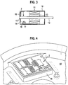
- Fig. 1 shows a circuit diagram representing the interconnection between the motor phase strands U, V, W of a synchronous motor 1 with a star point relay module 2.
- Each of the motor phase strands U, V, W is connected to a neutral point S via a suitable power switch 3, such as a MOSFET.
- the circuit breakers 3 are operated so that they are closed during normal operation of the engine system, so that the motor phase strands U, V, W are electrically connected to each other via the neutral point S.
- the star point relay module 2 comprises, as a carrier plate 21, a ceramic substrate on which conductor track structures are arranged as copper conductor tracks 22.
- the copper interconnects 22 form the terminals to the motor phase strands U, V, W of the synchronous motor 1.
- the neutral point S is formed as a conductor surface on the Keramiksubstart 21.
- On the support plate 21 further copper surfaces are provided, on which the MOSFET 3 are arranged so that the best possible heat dissipation from the MOSFET 3 to the copper surfaces 23 is possible. The contacting of the MOSFETs 3 takes place at least partially from the copper conductor tracks 22 opposite surface of the support plate 21.
- Fig. 3 is a cross-sectional view of a motor assembly according to an embodiment of the invention shown.
- the motor assembly comprises a motor housing 10, which is formed as a cylindrical sleeve, on the inner peripheral surface of motor coils are arranged to drive in a known manner, a motor shaft 12 via the permanent-magnet rotor 13 thereon by suitable control.
- the motor shaft 12 protrudes at one end of the motor housing 10 and serves as a motor output.
- a disc-shaped housing member 14 is provided, with which the corresponding side of the sleeve-shaped motor housing 10 is closed.
- the housing member 14 has an inwardly offset, substantially perpendicular from the main surface of the housing member 14 projecting, circumferential insertion edge 9, which is pushed into the interior of the motor housing 10 to position the housing member 14 on the motor housing 10.
- the housing element 14 has a central opening 15 through which an output of the opposite end of the motor shaft 12 projects, which is thereby mounted in the central opening.
- phase-strand connection 16 which in the assembled state is connected to a corresponding second phase-phase connection 17 which is fastened in the motor housing 10 so as to make contact with the motor phase strands U, V, W to allow from the outside via the housing member 14.
- the star point relay module 2 is arranged on the inside of the housing element 14 and it is thus possible that it has short connection lines to the motor phase strands, so that in normal operation, i. in the closed state of the circuit breaker 3 lowest possible connections of the motor phase strands can be realized with each other via the neutral point S.
- a control device 18 is preferably provided, which takes over the control of the synchronous motor in a suitable manner.
- the controller may continue to have the necessary functions.
- Fig. 4 a section of the housing element 14 is shown in perspective. It can be seen there that star point relay module 2 is arranged on a base 19 of the housing element 14.
- the base 19 protrudes from an inner surface of the housing member 14 in the motor interior and forms a surface against which the star point relay module 2.
- Base 19 and housing member 14 are preferably integrally formed and formed of a good heat conducting material such as a metal, or also of a non-conductive material such as a plastic material.
- the star point relay module 2 is placed on the base 19 of the Housing element 14 preferably glued or fastened by means of fasteners. In the latter case, a heat conducting paste can be provided between the base 19 and the housing element 14.
- the housing member 14 having a through hole 32.
- a contact guide member 30 is provided, which comprises a non-conductive plastic element or an element made of another non-conductive material.
- a via conductor 31 is embedded in the contact guide member 30, a via conductor 31 is embedded.
- the via conductor 31 may correspond to the control line for driving the power switches 3, and communicates with the star point relay module 2 on the inside of the case member 14 and with the controller 18 on the outside of the case member 14.
- the contact guide element 30 is formed substantially T-shaped and inserted from the inside of the housing member 14 in the through hole so that the legs of the contact guide element 30 abut against the inside of the housing member 14.
- One leg of the contact guide element 30 has a nose 33, which engages in a recess 34 on the inside of the contact guide element 30 in order to fix this.
- the invention is not limited to provide the star point relay module 2 on the housing element 14, which is provided as a flat completion of the cylindrical motor housing 10.
- the star point relay module 2 may be located at almost any location within the motor housing, as long as it does not affect the function of the motor.
- the arrangement of the star point relay module 2 in or on the housing of the motor assembly can be dispensed with additional housing components for secure recording of the star point relay module 2.
- the star point relay module 2 can as in Fig. 6 also be provided an electronic phase separation relay module 40.
- the motor phase strands U, V, W of the synchronous motor 1 are connected to each other as a star connection.
- the corresponding power switch 3 of the phase separation relay module 40 are arranged, which are closed in normal operation.
- Each of the power switches 3 is driven separately with a control line. In the event of a fault, the circuit breaker 3 are opened, so that no current can flow through the motor phase strands.
Landscapes
- Engineering & Computer Science (AREA)
- Microelectronics & Electronic Packaging (AREA)
- Power Engineering (AREA)
- Power Steering Mechanism (AREA)
- Motor Or Generator Frames (AREA)
Description
- Die Erfindung betrifft eine Motoranordnung, insbesondere einen Servoantrieb für ein elektronisches Lenksystem, in dem ein Trennrelais-Modul zur Stromlos-Schaltung der Motorphasen vorgesehen ist.
- Bei Servoantrieben, insbesondere bei elektronischen Lenksystemen, die z.B. einen Synchronmotor aufweisen, besteht im Falle eines Kurzschlusses der Motorphasen die Gefahr der Blockierung, sodass im oben genannten Beispiel das Fahrzeug unlenkbar werden könnte. Der Grund hierfür liegt darin, dass im Kurzschlussfall der Motor im Generatorbetrieb arbeitet, sodass ein Fahrzeuglenker dann zusätzlich zu den vollen Lenkkräften auf der Lenkachse noch gegen das Generatormoment des Synchronmotors arbeiten muss.
- Die Motorphasen sind bei einem Synchronmotor häufig in einer Sternpunktschaltung verschaltet. Zur Vermeidung eines Generatorbetriebs im Kurzschlussfall einer Phase kann ein mechanisch oder elektronisch ausgebildetes Sternpunktrelais vorgesehen sein, das im Fehlerfall die Motorphasen am Sternpunkt voneinander trennt.
- Ein typischer Mangel mechanischer Relais ist ihre geringere Ausfallssicherheit aufgrund mechanischer Ermüdung bzw. aufgrund blockierter Mechanikkomponenten, wodurch die Zuverlässigkeit des Trennens der Motorphasen eingeschränkt ist.
- Eine Steigerung der Zuverlässigkeit wird durch die Verwendung elektronischer Relais ermöglicht. Damit dieses auch unter schwierigen Umfeldbedingungen verwendet werden kann, muss dieses in geeigneter Weise mit dem Motorsystem verbunden sein. Weiterhin weisen die in elektronischen Sternpunktrelais verwendeten Leistungstransistoren im Normalbetrieb eine Wärmeentwicklung auf, die ein geeignetes Design zum Gewährleisten der Wärmeabfuhr notwendig macht. Dadurch wird eine geeignete Aufbau- und Verbindungstechnik erforderlich.
- Die Druckschrift
WO 98/10971 - Die Druckschrift
EP 0561 587 B1 offenbart einen Elektromotor mit zwei Kammern im Inneren eines Gehäuses, wobei ein Steuergerät in einer der Kammern angeordnet ist. - Es ist daher Aufgabe der vorliegenden Erfindung, ein Motorsystem, insbesondere für den Einsatz in einem elektronischen Lenksystem, zur Verfügung zu stellen, bei dem ein elektronisches Sternpunktrelais in vorteilhafter Weise integriert ist, niederohmig mit den Motorphasen verbunden werden kann und in besonderer Platz sparender Weise so angeordnet ist, dass weiterhin die Zuverlässigkeit und Ausfallsicherheit erhöht ist.
- Diese Aufgabe wird durch das Motorsystem nach Anspruch 1 gelöst.
- Weitere vorteilhafte Ausgestaltungen der Erfindung sind in den abhängigen Ansprüchen angegeben.
- Gemäß einem Aspekt ist eine Motoranordnung, insbesondere zur Verwendung in einem elektronischen Lenksystem, vorgesehen. Die Motoranordnung umfasst einen mehrphasigen Motor in einem Motorgehäuse, ein Gehäuseelement, das ein Teil des Motorgehäuses bildet, sowie ein elektronisches Trennrelais-Modul, um in einem Fehlerfall eine oder mehrere Motorphasen stromlos zu schalten. Das Trennrelais-Modul ist an einer Seite des Gehäuseelementes im Gehäuseinneren angeordnet.
- Die Motoranordnung sieht vor, ein elektronisches Trennrelais-Modul zur Abschaltung der Motorphasenstränge so anzuordnen, dass eine besonders kompakte Motoranordnung realisiert wird, die sich zum Einsatz in einem elektronischen Lenksystem besonders eignet. Dabei wird das Trennrelais-Modul im Gehäuseinneren an einem Gehäuseelement angeordnet, so dass das Trennrelais-Modul sowohl eine geeignete Wärmeableitung durch das Gehäuseelement erhält, als auch durch das Motorgehäuse vor Umgebungseinflüssen geschützt ist.
- Erfindungsgemäß wird ein Kontaktführungselement vorgesehen sein, das nicht-leitend mit einem Durchgangsleiter vorgesehen ist und in eine Durchgangsöffnung des Gehäuseelementes reicht, um eine Kontaktierung zwischen einer Innenseite und Außenseite des Gehäuseelementes zu schaffen.
- Weiterhin kann das Trennrelais-Modul auf einer Leiterplatte, insbesondere einer Keramik-Leiterplatte, angeordnet sein, die auf einer Erhebung, die auf einer ins Gehäuseinneren gerichteten Fläche des Gehäuseelementes ausgebildet ist, angeordnet ist.
- Gemäß einer Ausführungsform ist das Trennrelais-Modul als Sternpunktrelais-Modul oder als Phasentrennrelais-Modul ausgebildet.
- Das Kontaktführungselement kann weiterhin mit einem Schenkel ausgebildet sein, der sich zumindest teilweise an der Seite des Gehäuseelementes erstreckt, und ein Halteelement, insbesondere eine Nase, aufweist, das mit einem entsprechenden Haltelement, insbesondere einer Ausnehmung, zusammenwirkt, um das Kontaktführungselement zu halten.
- Weiterhin kann auf einer gegenüberliegenden Seite des Gehäuseelementes ein Steuergerät vorgesehen sein, um den Betrieb des Motors und insbesondere des Trennrelais-Moduls zu steuern.
- Gemäß einer Ausführungsform ist das Gehäuseelement flächig ausgebildet, um ein zylinderförmiges Gehäuseteil abzudecken.
- Bevorzugte Ausführungsformen der Erfindung werden nachfolgend anhand der beigefügten Zeichnung näher erläutert. Es zeigen:
- Fig. 1
- ein Schaltbild einer Motoranordnung mit drei Phasen, die in einer Sternschaltung mit einem Sternpunktrelais verschaltet sind;
- Fig. 2
- eine perspektivische Ansicht eines SternpunktrelaisModul zum Einsatz in einer Motoranordnung gemäß einer Ausführungsform der Erfindung;
- Fig. 3
- einen Querschnitt durch eine Motoranordnung eines Synchronmotors mit einem eingebauten Sternpunktrelais-Modul gemäß der Ausführungsform der vorliegenden Erfindung;
- Fig. 4
- eine perspektivische Ansicht eines Ausschnitts eines Gehäuseelementes der Motoranordnung mit dem darauf angeordneten Sternpunktrelais-Modul gemäß einer Ausführungsform der Erfindung;
- Fig. 5
- einen Querschnitt durch einen Abschnitt des Gehäuseelementes mit einem Durchkontaktierungselement zur Verbindung des Sternpunktrelais-Moduls mit einem Steuergerät zum Ansteuern des Motors in der Motoranordnung; und
- Fig. 6
- ein Schaltbild einer Motoranordnung mit drei Phasen, die in einer Sternschaltung verschaltet sind und durch ein Phasentrennrelais-Modul stromlos geschaltet werden können.
-
Fig. 1 zeigt ein Schaltbild, das die Verschaltung zwischen den Motorphasensträngen U, V, W eines Synchronmotors 1 mit einem Sternpunktrelais-Modul 2 darstellt. Jeder der Motorphasenstränge U, V, W ist über einen geeigneten Leistungsschalter 3, wie z.B. ein MOSFET, mit einem Sternpunkt S verbunden. Die Leistungsschalter 3 werden so betrieben, dass sie im Normalbetriebsfall des Motorsystems geschlossen sind, sodass die Motorphasenstränge U, V, W über den Sternpunkt S miteinander elektrisch verbunden sind. - Im Fehlerfall, z. B. bei einem Kurzschluss in einem der Motorphasenstränge U, V, W oder ähnlichem, werden die Leistungsschalter 3 geöffnet und somit die Motorphasenstränge U, V, W von dem Sternpunkt S getrennt. Dadurch wird der Stromfluss in den Motorphasensträngen unmittelbar unterbrochen und ein Bremsmoment des Synchronmotors bzw. ein Generatormoment kann vermieden werden, da die Motorphasenstränge sofort mit dem Öffnen der Leistungsschalter 3 stromlos geschaltet sind. Das Schalten der Leistungsschalter 3 wird mit Hilfe eines Ansteuersignals auf einer Steuerleitung vorgenommen, die bei einer Ausgestaltung mit MOSFETs mit deren Gate-Anschlüssen verbunden ist.
- In
Fig. 2 ist eine Ausführungsform eines Sternpunktrelais-Moduls 2 perspektivisch dargestellt. Das Sternpunktrelais-Modul 2 umfasst als eine Trägerplatte 21 ein Keramiksubstrat, auf dem Leiterbahnstrukturen als Kupferleiterbahnen 22 angeordnet sind. Die Kupferleiterbahnen 22 bilden die Anschlüsse zu den Motorphasensträngen U, V, W des Synchronmotors 1. Weiterhin wird auch der Sternpunkt S als Leiterfläche auf dem Keramiksubstart 21 ausgebildet. Auf der Trägerplatte 21 sind weitere Kupferflächen vorgesehen, auf denen die MOSFET 3 so angeordnet sind, dass eine möglichst gute Wärmeableitung von dem MOSFET 3 zu den Kupferflächen 23 möglich ist. Die Kontaktierung der MOSFETs 3 erfolgt zumindest teilweise von der den Kupferleiterbahnen 22 gegenüberliegenden Fläche der Trägerplatte 21 aus. - In
Fig. 3 ist eine Querschnittsansicht einer Motoranordnung gemäß einer Ausführungsform der Erfindung dargestellt. Die Motoranordnung umfasst ein Motorgehäuse 10, das als zylindrische Hülse ausgebildet ist, an deren inneren Umfangsfläche Motorspulen angeordnet sind, um in bekannter Weise eine Motorachse 12 über die daran befindlichen Permanentrotormagnete 13 durch geeignete Ansteuerung anzutreiben. Die Motorachse 12 ragt an einem Ende des Motorgehäuses 10 heraus und dient als Motorabtrieb. An einem dem Motorabtrieb gegenüberliegenden Ende des Motorgehäuses 10 ist ein scheibenförmiges Gehäuseelement 14 vorgesehen, mit dem die entsprechende Seite des hülsenförmigen Motorgehäuses 10 verschlossen ist. Das Gehäuseelement 14 weist eine nach innen versetzte, im wesentlichen senkrecht von der Hauptfläche des Gehäuseelementes 14 abstehende, umlaufende Einschubkante 9 auf, die in das Innere des Motorgehäuses 10 geschoben wird, um das Gehäuseelement 14 am Motorgehäuse 10 zu positionieren. Das Gehäuseelement 14 weist eine Mittenöffnung 15 auf, durch die ein dem Abtrieb gegenüberliegendes Ende der Motorachse 12 ragt, die dadurch in der Mittenöffnung gelagert ist. - Eine in Richtung des Motorgehäuses 10 gerichtete Innenseite des Gehäuseelementes 14 ist mit einem Phasenstranganschluss 16 versehen, der im zusammengesetzten Zustand mit einem entsprechenden zweiten Phasenstranganschluss 17, der im Motorgehäuse 10 befestigt ist, verbunden ist, um so eine Kontaktierung der Motorphasenstränge U, V, W von außen über das Gehäuseelement 14 zu ermöglichen.
- Das Sternpunktrelais-Modul 2 ist an der Innenseite des Gehäuseelementes 14 angeordnet und es ist somit möglich, das es kurze Verbindungsleitungen zu den Motorphasenstränge aufweist, sodass im Normalbetrieb, d.h. im geschlossenen Zustand der Leistungsschalter 3 möglichst niederohmige Verbindungen der Motorphasenstränge miteinander über den Sternpunkt S realisiert werden können.
- Auf der der Innenseite gegenüberliegende Außenseite des Gehäuseelementes 14 ist vorzugsweise ein Steuergerät 18 vorgesehen, das die Steuerung des Synchronmotors in geeigneter Weise übernimmt. Bei einem Einsatz der Motoranordnung in einem elektronischen Lenksystem kann das Steuergerät weiterhin die dafür notwendigen Funktionen aufweisen.
- In
Fig. 4 ist ein Ausschnitt des Gehäuseelementes 14 perspektivisch dargestellt. Man erkennt dort, dass Sternpunktrelais-Modul 2 auf einem Sockel 19 des Gehäuseelementes 14 angeordnet ist. Der Sockel 19 ragt von einer Innenfläche des Gehäuseelementes 14 in das Motorinnere und bildet eine Fläche, an der das Sternpunktrelais-Modul 2 anliegt. Sockel 19 und Gehäuseelement 14 sind vorzugsweise einstückig ausgebildet und aus einem gut wärmeleitenden Material wie z.B. einem Metall, oder auch aus einem nicht leitenden Material wie z.B. einem Kunststoffmaterial gebildet. Das Sternpunktrelais-Modul 2 wird auf den Sockel 19 des Gehäuseelementes 14 vorzugsweise geklebt oder mit Hilfe von Befestigungselementen befestigt. Im letzteren Fall ist kann zwischen Sockel 19 und Gehäuseelement 14 eine Wärmeleitepaste vorgesehen sein. - Wie in dem Ausschnitt des Gehäuseelementes der
Fig. 5 gezeigt kann zur Realisierung der Durchkontaktierung für zumindest die Steuerleitung das Gehäuseelement 14 eine Durchgangsöffnung 32 aufweisen. Darin ist ein Kontaktführungselement 30 vorgesehen, das ein nicht leitendes Kunststoffelement oder ein Element aus einem anderen nicht-leitenden Material aufweist. In dem Kontaktführungselement 30 ist ein Durchgangsleiter 31 eingebettet. Der Durchgangsleiter 31 kann der Steuerleitung zum Ansteuern der Leistungsschalter 3 entsprechen und steht mit dem Sternpunktrelais-Modul 2 auf der Innenseite des Gehäuseelementes 14 und mit dem Steuergerät 18 an der Außenseite des Gehäuseelements 14 in Verbindung. - Das Kontaktführungselement 30 ist im wesentlichen T-förmig ausgebildet und von der Innenseite des Gehäuseelementes 14 so in die Durchgangsöffnung hindurch gesteckt, dass die Schenkel des Kontaktführungselementes 30 an der Innenseite des Gehäuseelementes 14 anliegen. Ein Schenkel des Kontaktführungselement 30 weist ein Nase 33 auf, die in eine Ausnehmung 34 an der Innenseite des Kontaktführungselementes 30 eingreift, um dieses zu fixieren.
- Die Erfindung ist nicht darauf beschränkt, das Sternpunktrelais-Modul 2 an dem Gehäuseelement 14 vorzusehen, das als flächiger Abschluss des zylinderförmigen Motorgehäuses 10 vorgesehen ist. Bei anderen Motoranordnungen kann das Sternpunktrelais-Modul 2 an nahezu beliebiger Stelle innerhalb des Motorgehäuses angeordnet sein, so lange es die Funktion des Motors nicht beeinträchtigt. Durch die Anordnung des Sternpunktrelais-Moduls 2 in bzw. am Gehäuse der Motoranordnung kann auf zusätzliche Gehäusekomponenten zur sicheren Aufnahme des Sternpunktrelais-Moduls 2 verzichtet werden.
- An Stelle des Sternpunktrelais-Moduls 2 kann wie in
Fig. 6 gezeigt auch ein elektronisches Phasentrennrelaismodul 40 vorgesehen sein. Bei dieser Ausführungsform sind die Motorphasenstränge U, V, W des Synchronmotors 1 als Sternschaltung miteinander verbunden. Zwischen dem Steuergerät 18 und den Motorphasensträngen U, V, W sind die entsprechenden Leistungsschalter 3 des Phasentrennrelaismoduls 40 angeordnet, die im Normalbetriebsfall geschlossen sind. Jeder der Leistungsschalter 3 ist separat mit einer Steuerleitung angesteuert. Im Fehlerfall werden die Leistungsschalter 3 geöffnet, sodass durch die Motorphasenstränge kein Strom mehr fließen kann.
Claims (6)
- Motoranordnung, insbesondere zur Verwendung in einem elektronischen Lenksystem, umfassend:- einen mehrphasigen Motor (1) in einem Motorgehäuse (10);- ein Gehäuseelement (14), das ein Teil des Motorgehäuses (10) bildet;- ein elektronisches Trennrelais-Modul (2, 40), um in einem Fehlerfall eine oder mehrere Motorphasen stromlos zu schalten, dadurch gekennzeichnet, dass das Trennrelais-Modul (2, 40) an einer Innenseite des Gehäuseelementes (14) im Gehäuseinneren des Motorgehäuses (10) angeordnet ist,und dass
ein Kontaktführungselement (30) vorgesehen ist, das nichtleitend mit einem Durchgangsleiter (31) versehen ist und in eine Durchgangsöffnung (32) des Gehäuseelementes (14) reicht, um eine Kontaktierung zwischen einer Innenseite und Außenseite des Gehäuseelementes (14) zu schaffen, und dass der Durchgangsleiter (31) das Trennrelais-Modul (2; 40) auf der Innenseite des Gehäuseelements (14) und ein Steuergerät (18) an der gegenüberliegenden Außenseite des Gehäuseelements (14) miteinander verbindet, wobei das Steuergerät (18) vorgesehen ist , um den Betrieb des Motors (1) und des Trennrelais-Moduls (2, 40) zu steuern. - Motoranordnung nach Anspruch 1, dadurch gekennzeichnet, dass das Trennrelais-Modul (2, 40) auf einer Leiterplatte (21), insbesondere einer Keramik-Leiterplatte, angeordnet ist, die auf einer Erhebung (19), die auf einer ins Gehäuseinneren gerichteten Fläche des Gehäuseelementes (14) ausgebildet ist, angeordnet ist.
- Motoranordnung nach Anspruch 1 oder 2, dadurch gekennzeichnet, dass das Trennrelais-Modul (2, 40) als Sternpunktrelais-Modul oder als Phasentrennrelais-Modul ausgebildet ist.
- Motoranordnung nach einem der Ansprüche 1 bis 3, dadurch gekennzeichnet, dass das Kontaktführungselement (30) mit einem Schenkel ausgebildet ist, der sich zumindest teilweise an der Seite des Gehäuseelementes (14) erstreckt, und ein Halteelement (33), insbesondere eine Nase, aufweist, das mit einem entsprechenden Haltelement (34), insbesondere einer Ausnehmung, zusammenwirkt, um das Kontaktführungselement (30) zu halten.
- Motoranordnung nach einem der Ansprüche 1 bis 4, dadurch gekennzeichnet, dass das Gehäuseelement (14) flächig ausgebildet ist, um ein zylinderförmiges Gehäuseteil (10) abzudecken.
- Verwendung der Motoranordnung nach einem der Ansprüche 1 bis 5 in einem elektronischen Lenksystem.
Applications Claiming Priority (2)
| Application Number | Priority Date | Filing Date | Title |
|---|---|---|---|
| DE102007021491A DE102007021491A1 (de) | 2007-05-08 | 2007-05-08 | Motoranordnung mit elektronischem Trennrelais-Modul |
| PCT/EP2008/053298 WO2008135309A1 (de) | 2007-05-08 | 2008-03-19 | Motoranordnung mit elektronischem trennrelais-modul |
Publications (2)
| Publication Number | Publication Date |
|---|---|
| EP2147498A1 EP2147498A1 (de) | 2010-01-27 |
| EP2147498B1 true EP2147498B1 (de) | 2016-02-24 |
Family
ID=39657061
Family Applications (1)
| Application Number | Title | Priority Date | Filing Date |
|---|---|---|---|
| EP08718019.6A Active EP2147498B1 (de) | 2007-05-08 | 2008-03-19 | Motoranordnung mit elektronischem trennrelais-modul |
Country Status (6)
| Country | Link |
|---|---|
| US (1) | US8314584B2 (de) |
| EP (1) | EP2147498B1 (de) |
| JP (1) | JP5174892B2 (de) |
| CN (1) | CN101682235B (de) |
| DE (1) | DE102007021491A1 (de) |
| WO (1) | WO2008135309A1 (de) |
Families Citing this family (5)
| Publication number | Priority date | Publication date | Assignee | Title |
|---|---|---|---|---|
| ITMO20030259A1 (it) | 2003-09-25 | 2005-03-26 | Gambro Lundia Ab | User interface per una macchina per il trattamento |
| EP2597757B1 (de) * | 2011-11-24 | 2014-01-08 | Maxon Motor AG | Elektromotor für Hochtemperaturanwendungen |
| US9634604B2 (en) | 2013-04-30 | 2017-04-25 | Nxp Usa, Inc. | Device for controlling a multi-phase motor |
| DE102016106558A1 (de) | 2016-04-11 | 2017-10-12 | Festool Gmbh | Hand-Werkzeugmaschine mit einem Trennschalter |
| KR102898740B1 (ko) * | 2023-10-12 | 2025-12-11 | (주)비젼테크 | 수중 모터 누설 전류 제한 포집망 |
Family Cites Families (14)
| Publication number | Priority date | Publication date | Assignee | Title |
|---|---|---|---|---|
| US3903456A (en) * | 1974-01-28 | 1975-09-02 | Franklin Electric Co Inc | Protector system for an electric motor |
| US4603269A (en) * | 1984-06-25 | 1986-07-29 | Hochstein Peter A | Gated solid state FET relay |
| US5138177A (en) * | 1991-03-26 | 1992-08-11 | At&T Bell Laboratories | Solid-state relay |
| US5220197A (en) * | 1991-07-22 | 1993-06-15 | Silicon Power Corporation | Single inline packaged solid state relay with high current density capability |
| US5245237A (en) * | 1992-03-19 | 1993-09-14 | General Electric Company | Two compartment motor |
| DE69233166T2 (de) | 1992-10-06 | 2004-06-24 | Minebea K.K. | Zweireihiges Kugellager |
| AU5464094A (en) | 1992-11-11 | 1994-06-08 | Unilever Plc | Cosmetic composition containing succinic acid esters |
| GB9619175D0 (en) * | 1996-09-13 | 1996-10-23 | Lucas Ind Plc | Electrical power-assisted steering systems |
| JP3622362B2 (ja) * | 1996-09-19 | 2005-02-23 | 株式会社デンソー | 電動式パワーステアリング装置 |
| US6542062B1 (en) * | 1999-06-11 | 2003-04-01 | Tecumseh Products Company | Overload protector with control element |
| WO2001065666A1 (de) * | 2000-03-01 | 2001-09-07 | Robert Bosch Gmbh | Fail-safe für bürstenloser gleichstromantrieb |
| DE10223139A1 (de) | 2002-05-24 | 2003-12-11 | Bosch Gmbh Robert | Elektronisch kommutierbarer Motor |
| JP4405428B2 (ja) * | 2005-05-11 | 2010-01-27 | 本田技研工業株式会社 | モータ端子部構造 |
| US7276871B2 (en) * | 2005-07-25 | 2007-10-02 | Honeywell International, Inc. | System and method for fault protection for permanent magnet machines |
-
2007
- 2007-05-08 DE DE102007021491A patent/DE102007021491A1/de not_active Withdrawn
-
2008
- 2008-03-19 CN CN2008800153141A patent/CN101682235B/zh active Active
- 2008-03-19 JP JP2010506873A patent/JP5174892B2/ja not_active Expired - Fee Related
- 2008-03-19 WO PCT/EP2008/053298 patent/WO2008135309A1/de not_active Ceased
- 2008-03-19 EP EP08718019.6A patent/EP2147498B1/de active Active
- 2008-03-19 US US12/599,204 patent/US8314584B2/en not_active Expired - Fee Related
Also Published As
| Publication number | Publication date |
|---|---|
| WO2008135309A1 (de) | 2008-11-13 |
| CN101682235B (zh) | 2013-06-19 |
| JP5174892B2 (ja) | 2013-04-03 |
| US8314584B2 (en) | 2012-11-20 |
| US20100301713A1 (en) | 2010-12-02 |
| CN101682235A (zh) | 2010-03-24 |
| DE102007021491A1 (de) | 2008-11-13 |
| EP2147498A1 (de) | 2010-01-27 |
| JP2010526525A (ja) | 2010-07-29 |
Similar Documents
| Publication | Publication Date | Title |
|---|---|---|
| DE102007024659A1 (de) | Hilfskraftlenkung | |
| EP3935718B1 (de) | Steuergerät für ein lenksystem eines kraftfahrzeugs, elektromechanische kraftfahrzeugservolenkung und steer-by-wire lenksystem | |
| DE102010017514A1 (de) | Antriebsvorrichtung | |
| DE102010037045A1 (de) | Betriebssteuervorrichtung | |
| DE102010056120A1 (de) | Verschaltungseinrichtung für einen Elektromotor | |
| EP2327121A1 (de) | Aufnahmeeinheit für einen schaltungsträger, anschlusssystem, elektrische maschine mit aufnahmeeinheit sowie kraftfahrzeug mit derartiger elektrischer maschine | |
| EP2147498A1 (de) | Motoranordnung mit elektronischem trennrelais-modul | |
| WO2015090735A1 (de) | Schaltungsanordnung für einen notlauf eines mehrphasigen spannungswandlers mittels speziellen betriebsverfahren | |
| EP1733600B1 (de) | Motorsteuergerät | |
| WO2009018864A1 (de) | Elektromagnetisches schaltgerät mit mehreren relativ zueinander abgestuften bereichen | |
| DE102012101127A1 (de) | Servolenkvorrichtung eines kraftfahrzeugs | |
| EP1889354B1 (de) | Elektronische steuerungseinheit zur ansteuerung externer halbbrücken-leistungsendstufen und elektromotorischer antrieb mit elektronischer steuerungseinheit | |
| DE102008000145A1 (de) | Anordnung zum Ansteuern eines Drehstromantriebes | |
| EP1921733B1 (de) | Drehstrommotor und Steuervorrichtung | |
| EP3386097B1 (de) | Schaltung zum selektiven versorgen von motoren mit energie | |
| DE102022122704A1 (de) | Modulares System und Verfahren zum Bereitstellen eines Anschlussklemmenblocks und Anschlussklemmenblock | |
| DE102007041973B3 (de) | Vorrichtung zur Steuerung eines motorisch angetriebenen Schalterantriebs für ein Schaltgerät | |
| DE102021110656A1 (de) | Fremdkraftlenkeinheit für Lenkeinrichtung und Lenkeinrichtung für ein Fahrzeug | |
| BE1032600B1 (de) | Antriebseinheit für ein Lenksystem eines Kraftfahrzeugs | |
| EP1775744B1 (de) | Dreipoliger Leistungsschalter und Verfahren zu seiner Herstellung | |
| EP1748548A2 (de) | Schaltungsanordnung für den Betrieb eines in seiner Drehrichtung umkehrbaren Gleichstrommotors | |
| DE19545849A1 (de) | Anordnung zwischen einem Niederspannungsschalter und einem Türkupplungsgriff | |
| DE102008042975A1 (de) | Elektrische Maschine, Verfahren zum Herstellen eines Stators einer solchen Maschine und Lenkungsantriebsvorrichtung | |
| EP4362322B1 (de) | Elektromechanisches lenksystem mit einem doppelwicklungs-drehstrommotor und verfahren zum betreiben eines doppelwicklungs-drehstrommotors | |
| DE102009053320A1 (de) | Kreiselpumpenanordnung mit Steuer- und/oder Regelgerät |
Legal Events
| Date | Code | Title | Description |
|---|---|---|---|
| PUAI | Public reference made under article 153(3) epc to a published international application that has entered the european phase |
Free format text: ORIGINAL CODE: 0009012 |
|
| 17P | Request for examination filed |
Effective date: 20091208 |
|
| AK | Designated contracting states |
Kind code of ref document: A1 Designated state(s): AT BE BG CH CY CZ DE DK EE ES FI FR GB GR HR HU IE IS IT LI LT LU LV MC MT NL NO PL PT RO SE SI SK TR |
|
| AX | Request for extension of the european patent |
Extension state: AL BA MK RS |
|
| DAX | Request for extension of the european patent (deleted) | ||
| 17Q | First examination report despatched |
Effective date: 20120202 |
|
| GRAP | Despatch of communication of intention to grant a patent |
Free format text: ORIGINAL CODE: EPIDOSNIGR1 |
|
| INTG | Intention to grant announced |
Effective date: 20151006 |
|
| GRAS | Grant fee paid |
Free format text: ORIGINAL CODE: EPIDOSNIGR3 |
|
| GRAA | (expected) grant |
Free format text: ORIGINAL CODE: 0009210 |
|
| AK | Designated contracting states |
Kind code of ref document: B1 Designated state(s): AT BE BG CH CY CZ DE DK EE ES FI FR GB GR HR HU IE IS IT LI LT LU LV MC MT NL NO PL PT RO SE SI SK TR |
|
| REG | Reference to a national code |
Ref country code: GB Ref legal event code: FG4D Free format text: NOT ENGLISH |
|
| REG | Reference to a national code |
Ref country code: CH Ref legal event code: EP |
|
| REG | Reference to a national code |
Ref country code: AT Ref legal event code: REF Ref document number: 777185 Country of ref document: AT Kind code of ref document: T Effective date: 20160315 |
|
| REG | Reference to a national code |
Ref country code: IE Ref legal event code: FG4D Free format text: LANGUAGE OF EP DOCUMENT: GERMAN |
|
| REG | Reference to a national code |
Ref country code: FR Ref legal event code: PLFP Year of fee payment: 9 |
|
| REG | Reference to a national code |
Ref country code: DE Ref legal event code: R096 Ref document number: 502008013861 Country of ref document: DE |
|
| REG | Reference to a national code |
Ref country code: LT Ref legal event code: MG4D |
|
| REG | Reference to a national code |
Ref country code: NL Ref legal event code: MP Effective date: 20160224 |
|
| PG25 | Lapsed in a contracting state [announced via postgrant information from national office to epo] |
Ref country code: HR Free format text: LAPSE BECAUSE OF FAILURE TO SUBMIT A TRANSLATION OF THE DESCRIPTION OR TO PAY THE FEE WITHIN THE PRESCRIBED TIME-LIMIT Effective date: 20160224 Ref country code: ES Free format text: LAPSE BECAUSE OF FAILURE TO SUBMIT A TRANSLATION OF THE DESCRIPTION OR TO PAY THE FEE WITHIN THE PRESCRIBED TIME-LIMIT Effective date: 20160224 Ref country code: NO Free format text: LAPSE BECAUSE OF FAILURE TO SUBMIT A TRANSLATION OF THE DESCRIPTION OR TO PAY THE FEE WITHIN THE PRESCRIBED TIME-LIMIT Effective date: 20160524 Ref country code: FI Free format text: LAPSE BECAUSE OF FAILURE TO SUBMIT A TRANSLATION OF THE DESCRIPTION OR TO PAY THE FEE WITHIN THE PRESCRIBED TIME-LIMIT Effective date: 20160224 Ref country code: GR Free format text: LAPSE BECAUSE OF FAILURE TO SUBMIT A TRANSLATION OF THE DESCRIPTION OR TO PAY THE FEE WITHIN THE PRESCRIBED TIME-LIMIT Effective date: 20160525 |
|
| PG25 | Lapsed in a contracting state [announced via postgrant information from national office to epo] |
Ref country code: PT Free format text: LAPSE BECAUSE OF FAILURE TO SUBMIT A TRANSLATION OF THE DESCRIPTION OR TO PAY THE FEE WITHIN THE PRESCRIBED TIME-LIMIT Effective date: 20160624 Ref country code: LT Free format text: LAPSE BECAUSE OF FAILURE TO SUBMIT A TRANSLATION OF THE DESCRIPTION OR TO PAY THE FEE WITHIN THE PRESCRIBED TIME-LIMIT Effective date: 20160224 Ref country code: LV Free format text: LAPSE BECAUSE OF FAILURE TO SUBMIT A TRANSLATION OF THE DESCRIPTION OR TO PAY THE FEE WITHIN THE PRESCRIBED TIME-LIMIT Effective date: 20160224 Ref country code: PL Free format text: LAPSE BECAUSE OF FAILURE TO SUBMIT A TRANSLATION OF THE DESCRIPTION OR TO PAY THE FEE WITHIN THE PRESCRIBED TIME-LIMIT Effective date: 20160224 Ref country code: SE Free format text: LAPSE BECAUSE OF FAILURE TO SUBMIT A TRANSLATION OF THE DESCRIPTION OR TO PAY THE FEE WITHIN THE PRESCRIBED TIME-LIMIT Effective date: 20160224 Ref country code: NL Free format text: LAPSE BECAUSE OF FAILURE TO SUBMIT A TRANSLATION OF THE DESCRIPTION OR TO PAY THE FEE WITHIN THE PRESCRIBED TIME-LIMIT Effective date: 20160224 Ref country code: BE Free format text: LAPSE BECAUSE OF NON-PAYMENT OF DUE FEES Effective date: 20160331 |
|
| PG25 | Lapsed in a contracting state [announced via postgrant information from national office to epo] |
Ref country code: DK Free format text: LAPSE BECAUSE OF FAILURE TO SUBMIT A TRANSLATION OF THE DESCRIPTION OR TO PAY THE FEE WITHIN THE PRESCRIBED TIME-LIMIT Effective date: 20160224 Ref country code: EE Free format text: LAPSE BECAUSE OF FAILURE TO SUBMIT A TRANSLATION OF THE DESCRIPTION OR TO PAY THE FEE WITHIN THE PRESCRIBED TIME-LIMIT Effective date: 20160224 |
|
| REG | Reference to a national code |
Ref country code: CH Ref legal event code: PL |
|
| REG | Reference to a national code |
Ref country code: DE Ref legal event code: R097 Ref document number: 502008013861 Country of ref document: DE |
|
| PG25 | Lapsed in a contracting state [announced via postgrant information from national office to epo] |
Ref country code: RO Free format text: LAPSE BECAUSE OF FAILURE TO SUBMIT A TRANSLATION OF THE DESCRIPTION OR TO PAY THE FEE WITHIN THE PRESCRIBED TIME-LIMIT Effective date: 20160224 Ref country code: CZ Free format text: LAPSE BECAUSE OF FAILURE TO SUBMIT A TRANSLATION OF THE DESCRIPTION OR TO PAY THE FEE WITHIN THE PRESCRIBED TIME-LIMIT Effective date: 20160224 Ref country code: SK Free format text: LAPSE BECAUSE OF FAILURE TO SUBMIT A TRANSLATION OF THE DESCRIPTION OR TO PAY THE FEE WITHIN THE PRESCRIBED TIME-LIMIT Effective date: 20160224 |
|
| REG | Reference to a national code |
Ref country code: IE Ref legal event code: MM4A |
|
| PLBE | No opposition filed within time limit |
Free format text: ORIGINAL CODE: 0009261 |
|
| STAA | Information on the status of an ep patent application or granted ep patent |
Free format text: STATUS: NO OPPOSITION FILED WITHIN TIME LIMIT |
|
| GBPC | Gb: european patent ceased through non-payment of renewal fee |
Effective date: 20160524 |
|
| PG25 | Lapsed in a contracting state [announced via postgrant information from national office to epo] |
Ref country code: LI Free format text: LAPSE BECAUSE OF NON-PAYMENT OF DUE FEES Effective date: 20160331 Ref country code: IE Free format text: LAPSE BECAUSE OF NON-PAYMENT OF DUE FEES Effective date: 20160319 Ref country code: CH Free format text: LAPSE BECAUSE OF NON-PAYMENT OF DUE FEES Effective date: 20160331 |
|
| 26N | No opposition filed |
Effective date: 20161125 |
|
| PG25 | Lapsed in a contracting state [announced via postgrant information from national office to epo] |
Ref country code: SI Free format text: LAPSE BECAUSE OF FAILURE TO SUBMIT A TRANSLATION OF THE DESCRIPTION OR TO PAY THE FEE WITHIN THE PRESCRIBED TIME-LIMIT Effective date: 20160224 Ref country code: BG Free format text: LAPSE BECAUSE OF FAILURE TO SUBMIT A TRANSLATION OF THE DESCRIPTION OR TO PAY THE FEE WITHIN THE PRESCRIBED TIME-LIMIT Effective date: 20160524 |
|
| REG | Reference to a national code |
Ref country code: FR Ref legal event code: PLFP Year of fee payment: 10 |
|
| REG | Reference to a national code |
Ref country code: AT Ref legal event code: MM01 Ref document number: 777185 Country of ref document: AT Kind code of ref document: T Effective date: 20160319 |
|
| PG25 | Lapsed in a contracting state [announced via postgrant information from national office to epo] |
Ref country code: GB Free format text: LAPSE BECAUSE OF NON-PAYMENT OF DUE FEES Effective date: 20160524 |
|
| PG25 | Lapsed in a contracting state [announced via postgrant information from national office to epo] |
Ref country code: AT Free format text: LAPSE BECAUSE OF NON-PAYMENT OF DUE FEES Effective date: 20160319 Ref country code: MT Free format text: LAPSE BECAUSE OF FAILURE TO SUBMIT A TRANSLATION OF THE DESCRIPTION OR TO PAY THE FEE WITHIN THE PRESCRIBED TIME-LIMIT Effective date: 20160224 |
|
| REG | Reference to a national code |
Ref country code: FR Ref legal event code: PLFP Year of fee payment: 11 |
|
| PG25 | Lapsed in a contracting state [announced via postgrant information from national office to epo] |
Ref country code: HU Free format text: LAPSE BECAUSE OF FAILURE TO SUBMIT A TRANSLATION OF THE DESCRIPTION OR TO PAY THE FEE WITHIN THE PRESCRIBED TIME-LIMIT; INVALID AB INITIO Effective date: 20080319 Ref country code: CY Free format text: LAPSE BECAUSE OF FAILURE TO SUBMIT A TRANSLATION OF THE DESCRIPTION OR TO PAY THE FEE WITHIN THE PRESCRIBED TIME-LIMIT Effective date: 20160224 |
|
| PG25 | Lapsed in a contracting state [announced via postgrant information from national office to epo] |
Ref country code: TR Free format text: LAPSE BECAUSE OF FAILURE TO SUBMIT A TRANSLATION OF THE DESCRIPTION OR TO PAY THE FEE WITHIN THE PRESCRIBED TIME-LIMIT Effective date: 20160224 Ref country code: IS Free format text: LAPSE BECAUSE OF FAILURE TO SUBMIT A TRANSLATION OF THE DESCRIPTION OR TO PAY THE FEE WITHIN THE PRESCRIBED TIME-LIMIT Effective date: 20160224 Ref country code: LU Free format text: LAPSE BECAUSE OF NON-PAYMENT OF DUE FEES Effective date: 20160319 Ref country code: MC Free format text: LAPSE BECAUSE OF FAILURE TO SUBMIT A TRANSLATION OF THE DESCRIPTION OR TO PAY THE FEE WITHIN THE PRESCRIBED TIME-LIMIT Effective date: 20160224 |
|
| PGFP | Annual fee paid to national office [announced via postgrant information from national office to epo] |
Ref country code: IT Payment date: 20200325 Year of fee payment: 13 |
|
| PGFP | Annual fee paid to national office [announced via postgrant information from national office to epo] |
Ref country code: FR Payment date: 20200325 Year of fee payment: 13 |
|
| PG25 | Lapsed in a contracting state [announced via postgrant information from national office to epo] |
Ref country code: FR Free format text: LAPSE BECAUSE OF NON-PAYMENT OF DUE FEES Effective date: 20210331 |
|
| PG25 | Lapsed in a contracting state [announced via postgrant information from national office to epo] |
Ref country code: IT Free format text: LAPSE BECAUSE OF NON-PAYMENT OF DUE FEES Effective date: 20210319 |
|
| PGFP | Annual fee paid to national office [announced via postgrant information from national office to epo] |
Ref country code: DE Payment date: 20260526 Year of fee payment: 19 |