EP2147186B1 - Stormwater filter assembly - Google Patents
Stormwater filter assembly Download PDFInfo
- Publication number
- EP2147186B1 EP2147186B1 EP08769200.0A EP08769200A EP2147186B1 EP 2147186 B1 EP2147186 B1 EP 2147186B1 EP 08769200 A EP08769200 A EP 08769200A EP 2147186 B1 EP2147186 B1 EP 2147186B1
- Authority
- EP
- European Patent Office
- Prior art keywords
- center tube
- hood
- outer screen
- stormwater
- filter
- Prior art date
- Legal status (The legal status is an assumption and is not a legal conclusion. Google has not performed a legal analysis and makes no representation as to the accuracy of the status listed.)
- Active
Links
Images








Classifications
-
- E—FIXED CONSTRUCTIONS
- E21—EARTH OR ROCK DRILLING; MINING
- E21B—EARTH OR ROCK DRILLING; OBTAINING OIL, GAS, WATER, SOLUBLE OR MELTABLE MATERIALS OR A SLURRY OF MINERALS FROM WELLS
- E21B33/00—Sealing or packing boreholes or wells
- E21B33/10—Sealing or packing boreholes or wells in the borehole
- E21B33/12—Packers; Plugs
- E21B33/1208—Packers; Plugs characterised by the construction of the sealing or packing means
-
- B—PERFORMING OPERATIONS; TRANSPORTING
- B01—PHYSICAL OR CHEMICAL PROCESSES OR APPARATUS IN GENERAL
- B01D—SEPARATION
- B01D35/00—Filtering devices having features not specifically covered by groups B01D24/00 - B01D33/00, or for applications not specifically covered by groups B01D24/00 - B01D33/00; Auxiliary devices for filtration; Filter housing constructions
- B01D35/14—Safety devices specially adapted for filtration; Devices for indicating clogging
- B01D35/147—Bypass or safety valves
-
- B—PERFORMING OPERATIONS; TRANSPORTING
- B01—PHYSICAL OR CHEMICAL PROCESSES OR APPARATUS IN GENERAL
- B01D—SEPARATION
- B01D2201/00—Details relating to filtering apparatus
- B01D2201/04—Supports for the filtering elements
- B01D2201/0415—Details of supporting structures
-
- B—PERFORMING OPERATIONS; TRANSPORTING
- B01—PHYSICAL OR CHEMICAL PROCESSES OR APPARATUS IN GENERAL
- B01D—SEPARATION
- B01D2201/00—Details relating to filtering apparatus
- B01D2201/04—Supports for the filtering elements
- B01D2201/043—Filter tubes connected to plates
- B01D2201/0438—Filter tubes connected to plates mounted substantially vertically on plates at the lower side of the filter elements
-
- B—PERFORMING OPERATIONS; TRANSPORTING
- B01—PHYSICAL OR CHEMICAL PROCESSES OR APPARATUS IN GENERAL
- B01D—SEPARATION
- B01D2201/00—Details relating to filtering apparatus
- B01D2201/40—Special measures for connecting different parts of the filter
- B01D2201/4015—Bayonet connecting means
Definitions
- the present application relates generally to a filter apparatus and, in particular, a stormwater filter assembly having improved installation features.
- Stormwater is pure rainwater plus any particulate debris and dissolved materials that the rainwater may entrain as it traverses a surface.
- rain that falls on the roofs of buildings collects on paved areas like driveways, roads, runways and sidewalks is typically diverted through a system of pipes, catch basins, etc. that is separate from the sewage system.
- stormwater historically has not been treated, but flowed directly from streets and gutters into natural bodies of water, e.g., rivers, lakes and the ocean.
- Stormwater can therefore be a form of diffuse or non-point source pollution. It can entrain pollutants, such as garbage, sediment, organic matter, heavy metals, and organic toxins, and transport them into receiving natural bodies of water. As a consequence, natural bodies of water that receive stormwater may also receive the pollutants.
- pollutants such as garbage, sediment, organic matter, heavy metals, and organic toxins
- the amount of stormwater pollution entering into such receiving bodies of water is related to the degree of urbanization in the surrounding area and the nature of the surrounding activities.
- Urbanization results in the covering of land with structures of various permeabilities, such as roadways, parking lots, and rooftops, which both generate large volumes of stormwater and accumulate pollutants. Since some of these surfaces do not allow rainfall to infiltrate, they allow the accumulated pollutants to be carried into stormwater drainage systems.
- a filter apparatus described in U.S. Pat. No. 6,027,639 features a siphon-inducing mechanism.
- the filter apparatus of the '639 patent utilizes a sealed upper housing that includes a check valve for air evacuation within the housing. An induced siphon effect pulls stormwater through the filter until air is pulled through an air inlet along the lower perimeter of the housing, disrupting the siphon.
- a filter assembly includes a removable filter media basket contained within an external hood designed to house a bed of filtration material or filter medium.
- the media basket has a permeable outer screen and a permeable inner drainage space that collects the filtered water after it passes through the filter medium.
- the filter medium allows fluid communication between the outside environment and the inner drainage space.
- a drain manifold connects to the drainage space via a bushing, which both allows the flow of treated stormwater out of the filter assembly and serves as a component of a float valve assembly. This bushing serves as the connection point between the cartridge and a containment structure that houses one or more such filter assemblies.
- the present invention consists in a stormwater treatment system for filtering stormwater, comprising a filter assembly including: a bottom; a center tube secured to the bottom;a hood secured to the center tube; and a filter medium located between the hood and the center tube; characterized in that the bottom includes a boss; the center tube is secured to the bottom using a locking mechanism that inhibits relative movement between the bottom and the center tube, the center tube being in communication with an opening in the bottom; wherein to connect the center tube to the bottom, tube tabs are aligned to spaces between boss tabs and the center tube is fitted onto the boss, when the center tube bottoms out on the bottom, the center tube is rotated so that ends of boss tabs slide over curved surfaces of hooks on the tube tabs causing the tube tabs to deflect outwardly until protrusions on boss tabs move past the hooks and the tube tabs snap back radially inwardly; the boss includes a rib extending laterally along an inner surface of the boss, the rib including a locking portion
- the present invention consists in a method of assembling and installing a filter cartridge assembly for use in filtering stormwater, the method comprising: connecting a hood, center tube and bottom to form a filter cartridge;assembly containing filter media; and connecting the filter cartridge assembly to a deck stub; using a locking mechanism that inhibits relative movement between the bottom and the center tube, the center tube being in communication with an opening in the bottom;
- a stormwater treatment system for use in filtering stormwater includes an outlet conduit connection that connects to a filter conduit for use in delivering filtered stormwater toward an outlet of the stormwater treatment system.
- the outlet conduit connection includes a locking portion on a peripheral surface of the outlet conduit connection.
- a filter assembly includes a bottom including a boss that includes a rib extending laterally along an inner surface of the boss. The rib includes a locking portion that mates with the snap lock portion on the peripheral surface of the outlet conduit connection for securing the bottom to the outlet conduit connection thereby inhibiting rotation of the bottom relative to the outlet conduit connection.
- a center tube is secured to the bottom using a locking mechanism that inhibits relative movement between the bottom and the center tube. The center tube is in communication with an opening in the bottom and the outlet conduit connection.
- a hood is secured to the center tube.
- a filter media is between the hood and the center tube.
- a filter assembly for use in filtering stormwater includes a drainage space within the housing structure.
- a filter medium is between the drainage space and housing structure.
- the housing structure includes a lower portion with a mount opening for mating with an outlet conduit connection.
- the mount opening includes a pair of circumferentially extending and diametrically opposed ribs extending radially inwardly.
- the disclosed filter assembly includes a filter media with a vertically oriented filtration surface.
- the filter media is contained within an external housing, cover or hood with, in some embodiments, a plurality of voids located near its lower perimeter.
- the hood is designed to house and facilitate the filtration of stormwater through the filter media as well as to promote the development and maintenance of a siphon, which is located between a permeable outer screen and a permeable center tube.
- the filter assembly includes several features that facilitate assembly and installation of the filter assembly, for example, within a containment structure.
- a manifold of filter assemblies 10 is shown in Fig. 1 .
- the filter assemblies are typically housed in a containment structure 12 (e.g., a concrete vault or other tank configuration) that is generally adapted to receive stormwater runoff from a stormwater drainage pipe, a parking lot, a street or other surface.
- the containment structure 12 includes an initial configuration that allows for stormwater to bypass the manifold of filter assemblies 10 during the site construction phase. After this site construction phase, the containment structure is changed to a normal filtering configuration where incoming stormwater is filtered using the filter assemblies 10.
- a given containment structure 12 may contain only a single filter assembly 10, but typically contains two or more filter assemblies.
- the filter assemblies 10 may drain filtered stormwater into a filter conduit 14 that directs the filtered stormwater toward an outlet. While the filter conduit 14 is shown as having a circular cross-section, it may have a different cross-sectional shape such as rectangular.
- the filtered stormwater leaving the containment structure may be released into a receiving water body or waterway or diverted to additional treatment for further purification, as examples.
- the filter assembly 10 includes the hood 16 connected to a perforated or mesh center tube 18 having a drainage space 20 extending therethrough, with an inner drainage space cap 24 that engages an upward extending end of the center tube 18.
- Inner drainage space cap 24 contains a mechanism (e.g. a one-way check valve) to promote the development of a siphon by permitting air to be expelled from beneath the hood 16 without preventing air from flowing back into the filter assembly 10 through the inner drainage space cap.
- Center tube 18 is connected to a bottom 22 that forms a base for the filter assembly 10.
- the permeable outer screen 25 rests on the bottom 22, the outer screen extending vertically upward from the bottom and defining an annular volume between the center tube 18 and the outer screen.
- Flow through the filter assembly is controlled by a float valve assembly 28 that includes a buoyant float 30, a float valve body 32 and a linkage 34 joining the buoyant float and the float valve body.
- the float valve assembly 28 impedes or limits passage of stormwater from the filter assembly 10 when it is in its lowered position as illustrated.
- Filter media 36 is located within the annular volume between the center tube 18 and the outer screen 25.
- the filter media has a height of more than about 45.72 cm (18 inches), such as about 68.58 cm (27 inches) or more. In other embodiments, the filter media has a height of less than 45.72 cm (18 inches), such as about 30.48 cm (12 inches).
- the filter assembly 10 generally relies on hydraulic pressure to initially force water through the filter media and filter assembly is therefore at least partially submerged in stormwater during normal operation. As stormwater enters the filter assembly, infiltrates radially inward through the outer screen 25 and filter media 36, and into the drainage space 20, filtration occurs as the stormwater is strained through and comes into contact with the filter media.
- General operation of the filter assembly including siphon is similar to that described in pending U.S. Patent Serial No. 10/647,102, filed August 21, 2003 .
- the filter media 36 is selected to efficiently remove contaminants by physical filtration. Additionally, the filter media may be selected to remove contaminants through mechanical action, chemical action, biological action, or by any suitable combination thereof.
- a screen such as outer screen 25 is a satisfactory physical filter without the presence of additional filter media.
- the filter assembly may be capable of high throughput, rapidly screening debris from large volumes of stormwater.
- the filter includes outer screen 25 and one or more types of filter medium that is selected for finer filtration, for appropriate chemical reactivity, or appropriate biological activity. Mixtures of different media types are optionally used to provide advantageous combinations of filtering ability.
- the filter media 36 may be selected to remove heavy metals, oils and greases, organic toxins, and other contaminants that stormwater typically accumulates when flowing over paved areas in residential or industrial communities before entry into a stormwater treatment system. Alternatively, or in addition, the filter media 36 is selected to remove total or dissolved phosphorous or nitrogen from stormwater. Selected media include, without limitation, organic compost, vermiculite, activated carbon, peat, zeolite, perlite, diatomaceous earth, clay minerals, commercial ion exchange resins, catalyst-infused resins, silica sand, iron-infused media, or mixtures of these.
- the filter media 36 may be in the form of granules or pellets.
- the filter assembly 10 optionally includes a cloth or paper filter, including pleated filters.
- a cloth or paper filter either outside of or within the filter medium basket may be used to capture extremely fine particulates during filtration.
- outer screen 25 is shown generally as a right circular cylinder in the illustrated embodiment, other configurations are contemplated.
- an outer screen with an undulating, wavelike shape could be used to increase the filter surface area.
- Hood 16 includes a somewhat cylindrical body 38 (e.g., the diameter of the hood decreasing slightly when moving from the bottom toward the top of the hood) and a frustoconical top 40 (that gradually slopes upward when moving radially inward) having an opening 42 that is sized to allow the upper extending end of the center tube 18 to pass therethrough. Extending radially from a periphery 44 of the frustoconical top 40 to the opening 42 are a series of circumferentially spaced internal ribs 46 that intersect circumferential ribs 49, for providing increased support for the frustoconical top 40.
- the internal ribs 46 increase in height from the periphery 44 to the opening 42 forming somewhat of a triangle shape.
- a series of stacking ribs 47 extend radially outwardly from the outer and inner surfaces of the body 38 at the bottom of the hood 16. Specifically, each rib 47 is formed by an outward step 47A in the housing, with an internal strut 47B. The stacking ribs 47 maintain some spacing between stacked hoods 16. The internal struts 47B of an upper hood rest on the outward steps 47A of same underlying hood. Located between the stacking ribs 47 are slots 48 that extend to the bottom of the hood 16.
- center tube 18 includes the upper extending end 48 including a threaded region 50, for example, of coarse double threads, a perforated center section 52 including multiple openings 54 and a bottom section 56. Threaded region 50 mates with inner drainage space cap 24, described later. Below the threaded region 50 are sloped tabs 58 and a space 60 between the tabs for use in self-setting the hood 16 and locking the hood in position relative to the center tube 18. The alignment between the hood 16, tabs 58 and space 60 can be seen in Fig. 5 . As can be seen, extensions 61 of the hood 16 fit in the space 60 thereby aligning the hood. Referring again to Fig. 4 , a locking mechanism 62 is located at the bottom section 56 and is used to lock the center tube 18 to the bottom 22 using a cantilevered, elastically deflectable tab 64.
- the locking mechanism 62 includes the tab 64, which includes an outer raised rib 65 to provide added strength as well as a finger hold and a slot 69 for insertion of a tool, if required, for disconnecting the center tube 18 from the bottom 22.
- the tab 64 further includes an inward extending hook 71 (or other suitable structure) that interlocks with the bottom 22 and a positive stop 73 that inhibits over rotation of the center tube 18 when connecting to the bottom.
- a lower protrusion 75 interlocks with the bottom 22 to inhibit vertical movement of the center tube relative to the bottom. Additional details of the connection between the center tube 18 and bottom 22 will be described below.
- the inner drainage space cap 24 includes a cap body 66 having a threaded inner surface 67, for example, of coarse double threads to mate with the threaded region 50 of the center tube 18 ( Fig. 4 ).
- a rim 68 extends radially outward from the cap body 66 and includes a gasket 70 located at a lower portion of the rim.
- an outer diameter of the rim 68 may be about 13.59 cm (about 5.35 inches).
- the gasket 70 may be formed of a different material (e.g. a thermoplastic rubber) than the cap body 66 (e.g., acrylonitrile butadiene styrene).
- the gasket 70 is co-molded onto the inner drainage space cap 24, for example, using a two-shot injection molding process.
- the gasket 70 is used to form an air-tight seal between the inner drainage space cap 24 and hood 16.
- the cap 24 also compresses the frustoconical hood top 40 by deflecting it, which prestresses the hood to resist lift caused by trapped air and/or buoyant media.
- a pair of lifting structures 72 and 74 are located on opposite sides of a valve mechanism 76.
- the lifting structures have respective openings 78 and 80 that can be used to lift and transport the filter assembly 10, once assembled.
- the valve mechanism 76 includes a check valve cap 82 that surrounds and protects a check valve 84 from stormwater.
- Check valve 84 is located at a top of the inner drainage space cap 24, and engages a threaded portion 86 of the inner drainage space cap.
- the check valve cap 82 includes one or more channels 88 formed on the interior surface of the cap. Channels 88 permit the air escaping from beneath the filter hood via the check valve to escape from beneath cap 82, as indicated by the arrows in Fig. 9 .
- the inner surface of the check valve cap 82 also includes threaded regions 90 that are complementary to threaded portion 86 and that secure the check valve cap to the inner drainage space cap. Channels 88 in the check valve cap are configured so that even when the check valve cap is tightly engaged to the inner drainage space cap, the channels are unobstructed.
- the cap 82 is configured to maintain an air space above the valve 84 even when the filter assembly is completely submerged.
- bottom 22 (e.g., in the form of a pan) includes a substantially planar floor 92, a central boss 94 and an outer peripheral wall 96 that extends upward from the floor 92.
- a series of ribs 104 extend in a radial direction between the boss 94 and the peripheral wall 96.
- the ribs 104 stop short of the peripheral wall 96 forming a gap 106 therebetween.
- These gaps 106 are each sized to receive a bottom edge 110 of the outer screen 25 ( Fig. 11 ).
- the gaps 106 and peripheral wall 96 help to self-align and position the outer screen 25 during installation.
- each rib 104 Located adjacent the radially outer end of each rib 104 (or adjacent at least some of the ribs 104) are openings 108.
- the openings 108 extend through the peripheral wall 96 and are aligned with the ribs 104.
- the openings 108 are sized and located to receive self-tapping screws 111 (or other suitable fastener) after the outer screen 25 is positioned within the gaps 106 (see also Fig. 11 ).
- the screws 111 are tapped into the ends of ribs 104 for securing the bottom 22 to the outer screen 25.
- boss 94 which may be formed unitary with the floor 92, is sized and shaped to fit within bottom section 56 of center tube 18.
- the boss 94 includes a tab 98 that mates with the tab 64 of the center tube 18.
- tab 98 includes a protrusion 101 that can engage hook 71 of tab 64 to secure the center tube to the bottom 22 and to prevent relative rotation therebetween.
- a space 103 between a bottom of the boss and the tab 98 is sized and located to receive the lower protrusion 75 to inhibit vertical movement of the center tube 18 relative to the bottom 22.
- Boss 94 further includes an opening 100 that is sized to receive a conduit connection, sometimes referred to as a deck stub, described below.
- the boss 94 has internal ribs 102 with an enlarged locking portion 105 that mate with the deck stub to secure the bottom to the deck stub during installation. This also provides positive feedback that the filter is properly installed.
- the tube tabs 64 are aligned to spaces between the boss tabs 98 and the center tube 18 is fitted onto the boss 94.
- the center tube 18 bottoms out on the bottom 22, the center tube is rotated so that an end 107 of tab 98 (i.e., the end opposite the protrusion 101) slides over the curved surface of the hook 71 causing the tube tab 64 to deflect outwardly until the protrusion 101 moves past the hook and the tube tab snaps back radially inwardly. This may be a 90 degree rotation of the center tube 18.
- stop 73 prevents rotation of the center tube 18 relative to the bottom 22 in one direction by engaging end 107 of the tab 98, and hook 71 prevents rotation of the center tube in the opposite direction because the angled surface of protrusion 101 will move into the slot of the hook 71, preventing the tube tab 64 from deflecting radially outward.
- a top ring 112 is used to secure an upper edge 114 of the outer screen 25 ( Fig. 11 ).
- the top ring 112 is of a concentric dual-ring construction and includes an outer ring 116 and an inner ring 118 spaced radially from the outer ring, forming a groove 126 therebetween that is sized to receive the upper edge 114 of the screen.
- the outer ring 116 has an axial height H that is greater than that of the inner ring 118, which can aid in assembly.
- Inner ring 118 includes both internal and external ribs 120, 122 that are aligned with openings 124 extending through the outer ring 116.
- the openings 124 are sized and positioned to receive self-tapping screws 111 (or other suitable fastener) after the upper edge 114 is located within the groove 126.
- the screws 111 are tapped into the ribs 120, 122 for securing the top ring 112 to the outer screen 25 ( Fig. 11 ).
- Fig. 14 shows deck stub 130, which includes an upper portion 132 that connects to the bottom 22 and a lower portion 134 that connects to a drain conduit 136 (illustrated by dotted lines), for example, using ABS glue.
- a deck stub mount 139 is located between the deck stub 130 and the drain conduit 136.
- a rim 138 extending radially outwardly from the deck stub 130 is used to mate with and support the bottom 22, forming a fluid-tight seal therebetween.
- Upper portion 132 includes locking structure 140 forming a groove 137 that mates with ribs 102 of the bottom 22 to lock the bottom to the deck stub 130 during installation and inhibit movement (vertical and rotational) of the cartridge assembly 10.
- Positive stop portion 133 of the locking structure prevents over-rotation of the bottom 22 when connecting the bottom to the deck stub 130 and locking portion 135 mates with locking portion 105 of the boss 94.
- the ribs 102 are aligned with the spaces between the deck stub locking structure 140 and the bottom is rotated (e.g., about 90 degrees by applying a rotational force to the hood 16 once the filter assembly is assembled) so that the lock portion 105 of the boss 94 moves into the groove 137 until it reaches locking portion 135 providing a detent feature to hold the assembly in place.
- the rib 102 deflects while the portion 105 is within groove 137 and then snaps back once the portion 105 is within the locking portion 135.
- Figs. 15A and 15B illustrate the center tube 18, bottom 22 and deck stub 130 interconnected.
- the boss 94 is received within the bottom section 56 of center tube 18 and the upper portion 132 of the deck stub 130 is received within the opening 100 of the boss.
- the tab 98 of the boss is interlocked with the snap lock which includes tab 64 of the center tube 18 and the lower protrusion 75 is mated within the groove 103 ( Fig. 15A ).
- Deck stub 130 is interlocked with the bottom 22 using the rib 102 and locking structure 140, which inhibits both rotational and vertical movement of the bottom relative to the deck stub, except that the filter can be removed from the stub by rotating to overcome the detent force between portions 105 and 135.
- Figure 16 illustrates a process for assembling and installing the cartridge assembly 10.
- the center tube 18 is connected to the bottom 22 using the locking mechanism 62 of the center tube including the elastically deflectable tab 64 and tab 98 with protrusion 101 and ribs 102 of the bottom.
- the outer screen 25 is then placed on the bottom 22, within the grooves 106 and around the center tube 18 at step 144.
- the outer screen 25 typically overlaps itself and may be secured to itself using clips 146 by inserting a mating part 147 of the clips into the overlapped outer screen and turning the clips (e.g., 90 degrees) using the enlarged wing portion 149 (see Figs. 11 and 17 ).
- step 150 self-tapping screws are threaded into openings 108, through the outer screen 25 and into the ribs 104 which lock the outer screen 25 to the bottom 22.
- step 152 the top ring 112 is assembled to the outer screen 25 by sandwiching an upper end of the outer screen between the inner and outer rings 118 and 116.
- step 154 self-tapping screws are threaded into openings 124 in the top ring 112, which lock the outer screen 25 to the top ring.
- the float 30 is placed within the center tube 18 at step 156 (however, the float may be placed within the center tube 18 prior to or even after this step). Also at step 156, media is added to the filter basket.
- the filter hood 16 is positioned over the outer screen 25 and the top ring 112 with the threaded region 50 exposed through the top opening in the filter hood and the filter hood interlocks with the sloped tabs 58 and a cut in space 60 of the center tube 18.
- the inner drainage space cap 24 is then threaded onto the center tube 18 thereby applying a downward force on the hood 16 thereby maintaining the interlock between the filter hood and the center tube at step 162.
- the bottom 22 is connected to the deck stub 130 which is already connected to an outlet tube, for example, within a stormwater basin.
- the cartridge assembly 10 can be rotated as a unit, e.g., by applying a rotational force to the hood when threading the assembly onto (or off of) the deck stub 130.
Landscapes
- Geology (AREA)
- Life Sciences & Earth Sciences (AREA)
- Engineering & Computer Science (AREA)
- Mining & Mineral Resources (AREA)
- Environmental & Geological Engineering (AREA)
- Fluid Mechanics (AREA)
- Physics & Mathematics (AREA)
- General Life Sciences & Earth Sciences (AREA)
- Geochemistry & Mineralogy (AREA)
- Chemical & Material Sciences (AREA)
- Chemical Kinetics & Catalysis (AREA)
- Filtration Of Liquid (AREA)
- Sewage (AREA)
- Revetment (AREA)
- Structure Of Emergency Protection For Nuclear Reactors (AREA)
Description
- The present application relates generally to a filter apparatus and, in particular, a stormwater filter assembly having improved installation features.
- Stormwater is pure rainwater plus any particulate debris and dissolved materials that the rainwater may entrain as it traverses a surface. In urban areas, rain that falls on the roofs of buildings, collects on paved areas like driveways, roads, runways and sidewalks is typically diverted through a system of pipes, catch basins, etc. that is separate from the sewage system. Unlike sewage, stormwater historically has not been treated, but flowed directly from streets and gutters into natural bodies of water, e.g., rivers, lakes and the ocean.
- Stormwater can therefore be a form of diffuse or non-point source pollution. It can entrain pollutants, such as garbage, sediment, organic matter, heavy metals, and organic toxins, and transport them into receiving natural bodies of water. As a consequence, natural bodies of water that receive stormwater may also receive the pollutants.
- The amount of stormwater pollution entering into such receiving bodies of water is related to the degree of urbanization in the surrounding area and the nature of the surrounding activities. Urbanization results in the covering of land with structures of various permeabilities, such as roadways, parking lots, and rooftops, which both generate large volumes of stormwater and accumulate pollutants. Since some of these surfaces do not allow rainfall to infiltrate, they allow the accumulated pollutants to be carried into stormwater drainage systems.
- In an effort to address the environmental problems posed by polluted stormwater, systems which may include traps and filters for stormwater have been developed. For example, a filter apparatus described in
U.S. Pat. No. 6,027,639 features a siphon-inducing mechanism. The filter apparatus of the '639 patent utilizes a sealed upper housing that includes a check valve for air evacuation within the housing. An induced siphon effect pulls stormwater through the filter until air is pulled through an air inlet along the lower perimeter of the housing, disrupting the siphon. - In
US 2003/0094407 A1 , a filter assembly includes a removable filter media basket contained within an external hood designed to house a bed of filtration material or filter medium. The media basket has a permeable outer screen and a permeable inner drainage space that collects the filtered water after it passes through the filter medium. The filter medium allows fluid communication between the outside environment and the inner drainage space. A drain manifold connects to the drainage space via a bushing, which both allows the flow of treated stormwater out of the filter assembly and serves as a component of a float valve assembly. This bushing serves as the connection point between the cartridge and a containment structure that houses one or more such filter assemblies. - In an aspect, the present invention consists in a stormwater treatment system for filtering stormwater, comprising a filter assembly including: a bottom; a center tube secured to the bottom;a hood secured to the center tube; and a filter medium located between the hood and the center tube; characterized in that the bottom includes a boss; the center tube is secured to the bottom using a locking mechanism that inhibits relative movement between the bottom and the center tube, the center tube being in communication with an opening in the bottom; wherein to connect the center tube to the bottom, tube tabs are aligned to spaces between boss tabs and the center tube is fitted onto the boss, when the center tube bottoms out on the bottom, the center tube is rotated so that ends of boss tabs slide over curved surfaces of hooks on the tube tabs causing the tube tabs to deflect outwardly until protrusions on boss tabs move past the hooks and the tube tabs snap back radially inwardly; the boss includes a rib extending laterally along an inner surface of the boss, the rib including a locking portion that mates with a corresponding locking portion on a deck stub connected to an outlet conduit for securing the bottom to the deck stub thereby inhibiting rotation of the bottom relative to the outlet conduit.
- In another aspect, the present invention consists in a method of assembling and installing a filter cartridge assembly for use in filtering stormwater, the method comprising: connecting a hood, center tube and bottom to form a filter cartridge;assembly containing filter media; and connecting the filter cartridge assembly to a deck stub; using a locking mechanism that inhibits relative movement between the bottom and the center tube, the center tube being in communication with an opening in the bottom;
- In another example, a stormwater treatment system for use in filtering stormwater includes an outlet conduit connection that connects to a filter conduit for use in delivering filtered stormwater toward an outlet of the stormwater treatment system. The outlet conduit connection includes a locking portion on a peripheral surface of the outlet conduit connection. A filter assembly includes a bottom including a boss that includes a rib extending laterally along an inner surface of the boss. The rib includes a locking portion that mates with the snap lock portion on the peripheral surface of the outlet conduit connection for securing the bottom to the outlet conduit connection thereby inhibiting rotation of the bottom relative to the outlet conduit connection. A center tube is secured to the bottom using a locking mechanism that inhibits relative movement between the bottom and the center tube. The center tube is in communication with an opening in the bottom and the outlet conduit connection. A hood is secured to the center tube. A filter media is between the hood and the center tube.
- In another example, a filter assembly for use in filtering stormwater includes a drainage space within the housing structure. A filter medium is between the drainage space and housing structure. The housing structure includes a lower portion with a mount opening for mating with an outlet conduit connection. The mount opening includes a pair of circumferentially extending and diametrically opposed ribs extending radially inwardly.
- The details of one or more embodiments are set forth in the accompanying drawings and the description below. Other features, objects and advantages will be apparent from the description and drawings, and from the claims.
-
-
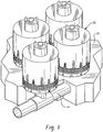
Fig. 1 is a perspective view of an embodiment of a manifold of filter assemblies; -
Fig. 2 is a section view of an embodiment of a filter assembly; -
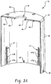
Fig. 3 is a perspective, side view of an embodiment of a hood for use with the filter assembly ofFig. 3 ; -
Fig. 3A is a section view along line A-A ofFig. 3 ; -
Fig. 4 is a side, section view of an embodiment of a center tube for use with the filter assembly ofFig. 2 ; -
Fig. 5 is a detail view of an interlock between the center tube ofFig. 4 and hood ofFig. 3 ; -
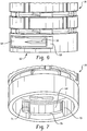
Figs. 6 and 7 are detail views of an embodiment of locking structure of the center tube ofFig. 4 for use in connecting the center tube to a bottom; -
Fig. 8 is a side view of an embodiment of an inner drainage space cap for use with the filter assembly ofFig. 2 ; -
Fig. 9 is a section view of the inner drainage space cap along line 9-9 ofFig. 8 ; -
Fig. 10 is a top view of an embodiment of a bottom for use with the filter assembly ofFig. 2 ; -
Fig. 10A is a detail view of area A ofFig. 10 ; -
Fig.11 is a side view of an embodiment of an outer screen for use with the filter assembly ofFig. 2 connected to the bottom ofFig. 10 and a top ring; -
Fig.12 is a section view detailing a connection between the center tube ofFig. 4 and the bottom ofFig. 10 ; -
Fig. 13 is a perspective, side view of an embodiment of a top ring for use with the filter assembly ofFig. 2 ; -
Fig. 14 is a perspective, top view of an embodiment of a deck stub for use with the filter assembly ofFig. 2 ; -
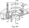
Fig. 15A is a section view detailing a connection between the center tube ofFig. 4 , the bottom ofFig. 10 and the deck stub ofFig. 14 ; -
Fig. 15B is a section view detailing the connection between the center tube ofFig. 4 , the bottom ofFig. 10 and the deck stub ofFig. 14 along line B-B ofFig. 15A ; -
Fig. 16 illustrates an embodiment of a method of assembling and installing the cartridge assembly ofFig. 2 ; and -
Fig. 17 is a perspective view of an embodiment of a clip for use in securing the outer screen ofFig. 11 to itself. - The disclosed filter assembly includes a filter media with a vertically oriented filtration surface. The filter media is contained within an external housing, cover or hood with, in some embodiments, a plurality of voids located near its lower perimeter. The hood is designed to house and facilitate the filtration of stormwater through the filter media as well as to promote the development and maintenance of a siphon, which is located between a permeable outer screen and a permeable center tube. As will be described in greater detail below, the filter assembly includes several features that facilitate assembly and installation of the filter assembly, for example, within a containment structure. While the description below focuses on a horizontal and radial flow-through filter assembly having a perforated center tube, similar features could be incorporated into other filter assembly configurations including a filtration assembly where the center tube is solid and/or in which the filter element is spiraled or in which flow through the filter is primarily upward.
- A manifold of
filter assemblies 10 is shown inFig. 1 . The filter assemblies are typically housed in a containment structure 12 (e.g., a concrete vault or other tank configuration) that is generally adapted to receive stormwater runoff from a stormwater drainage pipe, a parking lot, a street or other surface. In some embodiments, thecontainment structure 12 includes an initial configuration that allows for stormwater to bypass the manifold offilter assemblies 10 during the site construction phase. After this site construction phase, the containment structure is changed to a normal filtering configuration where incoming stormwater is filtered using thefilter assemblies 10. - A given
containment structure 12 may contain only asingle filter assembly 10, but typically contains two or more filter assemblies. Thefilter assemblies 10 may drain filtered stormwater into afilter conduit 14 that directs the filtered stormwater toward an outlet. While thefilter conduit 14 is shown as having a circular cross-section, it may have a different cross-sectional shape such as rectangular. The filtered stormwater leaving the containment structure may be released into a receiving water body or waterway or diverted to additional treatment for further purification, as examples. - Referring to
Fig. 2 , thefilter assembly 10 includes thehood 16 connected to a perforated ormesh center tube 18 having adrainage space 20 extending therethrough, with an innerdrainage space cap 24 that engages an upward extending end of thecenter tube 18. Innerdrainage space cap 24 contains a mechanism (e.g. a one-way check valve) to promote the development of a siphon by permitting air to be expelled from beneath thehood 16 without preventing air from flowing back into thefilter assembly 10 through the inner drainage space cap. -
Center tube 18 is connected to a bottom 22 that forms a base for thefilter assembly 10. The permeableouter screen 25 rests on the bottom 22, the outer screen extending vertically upward from the bottom and defining an annular volume between thecenter tube 18 and the outer screen. Flow through the filter assembly is controlled by afloat valve assembly 28 that includes abuoyant float 30, afloat valve body 32 and alinkage 34 joining the buoyant float and the float valve body. Thefloat valve assembly 28 impedes or limits passage of stormwater from thefilter assembly 10 when it is in its lowered position as illustrated. -
Filter media 36 is located within the annular volume between thecenter tube 18 and theouter screen 25. In some embodiments, the filter media has a height of more than about 45.72 cm (18 inches), such as about 68.58 cm (27 inches) or more. In other embodiments, the filter media has a height of less than 45.72 cm (18 inches), such as about 30.48 cm (12 inches). Thefilter assembly 10 generally relies on hydraulic pressure to initially force water through the filter media and filter assembly is therefore at least partially submerged in stormwater during normal operation. As stormwater enters the filter assembly, infiltrates radially inward through theouter screen 25 andfilter media 36, and into thedrainage space 20, filtration occurs as the stormwater is strained through and comes into contact with the filter media. General
operation of the filter assembly including siphon is similar to that described in pendingU.S. Patent Serial No. 10/647,102, filed August 21, 2003 - The
filter media 36 is selected to efficiently remove contaminants by physical filtration. Additionally, the filter media may be selected to remove contaminants through mechanical action, chemical action, biological action, or by any suitable combination thereof. In one aspect, a screen such asouter screen 25 is a satisfactory physical filter without the presence of additional filter media. The filter assembly may be capable of high throughput, rapidly screening debris from large volumes of stormwater. Alternatively, the filter includesouter screen 25 and one or more types of filter medium that is selected for finer filtration, for appropriate chemical reactivity, or appropriate biological activity. Mixtures of different media types are optionally used to provide advantageous combinations of filtering ability. - The
filter media 36 may be selected to remove heavy metals, oils and greases, organic toxins, and other contaminants that stormwater typically accumulates when flowing over paved areas in residential or industrial communities before entry into a stormwater treatment system. Alternatively, or in addition, thefilter media 36 is selected to remove total or dissolved phosphorous or nitrogen from stormwater. Selected media include, without limitation, organic compost, vermiculite, activated carbon, peat, zeolite, perlite, diatomaceous earth, clay minerals, commercial ion exchange resins, catalyst-infused resins, silica sand, iron-infused media, or mixtures of these. Thefilter media 36 may be in the form of granules or pellets. Large granules provide the advantage of maintaining a high flow rate through the treatment bed by minimizing clogging of the bed that might otherwise arise from the accumulation of fine particulate debris. Alternatively, fine granules provide enhanced filtration of fine debris. The selection of pellet or granule size depends on the desired level of physical straining and treatment. - The
filter assembly 10 optionally includes a cloth or paper filter, including pleated filters. The use of a cloth or paper filter either outside of or within the filter medium basket may be used to capture extremely fine particulates during filtration. - While the
outer screen 25 is shown generally as a right circular cylinder in the illustrated embodiment, other configurations are contemplated. For example, an outer screen with an undulating, wavelike shape could be used to increase the filter surface area. - Turning now to individual components of the filter assembly,
Figs. 3 and3A showhood 16 in isolation.Hood 16 includes a somewhat cylindrical body 38 (e.g., the diameter of the hood decreasing slightly when moving from the bottom toward the top of the hood) and a frustoconical top 40 (that gradually slopes upward when moving radially inward) having anopening 42 that is sized to allow the upper extending end of thecenter tube 18 to pass therethrough. Extending radially from aperiphery 44 of the frustoconical top 40 to theopening 42 are a series of circumferentially spacedinternal ribs 46 that intersectcircumferential ribs 49, for providing increased support for the frustoconical top 40. Theinternal ribs 46 increase in height from theperiphery 44 to theopening 42 forming somewhat of a triangle shape. A series of stackingribs 47 extend radially outwardly from the outer and inner surfaces of thebody 38 at the bottom of thehood 16. Specifically, eachrib 47 is formed by anoutward step 47A in the housing, with an internal strut 47B. The stackingribs 47 maintain some spacing betweenstacked hoods 16. The internal struts 47B of an upper hood rest on theoutward steps 47A of same underlying hood. Located between the stackingribs 47 areslots 48 that extend to the bottom of thehood 16. - Referring to
Fig. 4 ,center tube 18 includes the upper extendingend 48 including a threadedregion 50, for example, of coarse double threads, aperforated center section 52 includingmultiple openings 54 and abottom section 56. Threadedregion 50 mates with innerdrainage space cap 24, described later. Below the threadedregion 50 are slopedtabs 58 and aspace 60 between the tabs for use in self-setting thehood 16 and locking the hood in position relative to thecenter tube 18. The alignment between thehood 16,tabs 58 andspace 60 can be seen inFig. 5 . As can be seen,extensions 61 of thehood 16 fit in thespace 60 thereby aligning the hood. Referring again toFig. 4 , alocking mechanism 62 is located at thebottom section 56 and is used to lock thecenter tube 18 to the bottom 22 using a cantilevered, elasticallydeflectable tab 64. - Referring now to
Fig. 6 , thelocking mechanism 62 includes thetab 64, which includes an outer raisedrib 65 to provide added strength as well as a finger hold and aslot 69 for insertion of a tool, if required, for disconnecting thecenter tube 18 from the bottom 22. Referring toFig. 7 , thetab 64 further includes an inward extending hook 71 (or other suitable structure) that interlocks with the bottom 22 and apositive stop 73 that inhibits over rotation of thecenter tube 18 when connecting to the bottom. Alower protrusion 75 interlocks with the bottom 22 to inhibit vertical movement of the center tube relative to the bottom. Additional details of the connection between thecenter tube 18 and bottom 22 will be described below. - Referring now to
Fig. 8 , the innerdrainage space cap 24 includes acap body 66 having a threadedinner surface 67, for example, of coarse double threads to mate with the threadedregion 50 of the center tube 18 (Fig. 4 ). Arim 68 extends radially outward from thecap body 66 and includes agasket 70 located at a lower portion of the rim. In some embodiments, an outer diameter of therim 68 may be about 13.59 cm (about 5.35 inches). Thegasket 70 may be formed of a different material (e.g. a thermoplastic rubber) than the cap body 66 (e.g., acrylonitrile butadiene styrene). In some embodiments, thegasket 70 is co-molded onto the innerdrainage space cap 24, for example, using a two-shot injection molding process. Thegasket 70 is used to form an air-tight seal between the innerdrainage space cap 24 andhood 16. Thecap 24 also compresses thefrustoconical hood top 40 by deflecting it, which prestresses the hood to resist lift caused by trapped air and/or buoyant media. A pair of liftingstructures 72 and 74 are located on opposite sides of avalve mechanism 76. The lifting structures haverespective openings 78 and 80 that can be used to lift and transport thefilter assembly 10, once assembled. - Referring to
Fig. 9 , thevalve mechanism 76 includes acheck valve cap 82 that surrounds and protects acheck valve 84 from stormwater. Checkvalve 84 is located at a top of the innerdrainage space cap 24, and engages a threadedportion 86 of the inner drainage space cap. Thecheck valve cap 82 includes one ormore channels 88 formed on the interior surface of the cap.Channels 88 permit the air escaping from beneath the filter hood via the check valve to escape from beneathcap 82, as indicated by the arrows inFig. 9 . The inner surface of thecheck valve cap 82 also includes threadedregions 90 that are complementary to threadedportion 86 and that secure the check valve cap to the inner drainage space cap.Channels 88 in the check valve cap are configured so that even when the check valve cap is tightly engaged to the inner drainage space cap, the channels are unobstructed. Thecap 82 is configured to maintain an air space above thevalve 84 even when the filter assembly is completely submerged. - Referring to
Fig. 10 bottom 22 (e.g., in the form of a pan) includes a substantiallyplanar floor 92, acentral boss 94 and an outerperipheral wall 96 that extends upward from thefloor 92. As can be seen byFig. 10 , a series ofribs 104 extend in a radial direction between theboss 94 and theperipheral wall 96. Theribs 104 stop short of theperipheral wall 96 forming agap 106 therebetween. Thesegaps 106 are each sized to
receive abottom edge 110 of the outer screen 25 (Fig. 11 ). Thegaps 106 andperipheral wall 96 help to self-align and position theouter screen 25 during installation. - Located adjacent the radially outer end of each rib 104 (or adjacent at least some of the ribs 104) are
openings 108. Theopenings 108 extend through theperipheral wall 96 and are aligned with theribs 104. Theopenings 108 are sized and located to receive self-tapping screws 111 (or other suitable fastener) after theouter screen 25 is positioned within the gaps 106 (see alsoFig. 11 ). Thescrews 111 are tapped into the ends ofribs 104 for securing the bottom 22 to theouter screen 25. - Referring to
Fig. 10A ,boss 94, which may be formed unitary with thefloor 92, is sized and shaped to fit withinbottom section 56 ofcenter tube 18. Referring also toFig. 12 , theboss 94 includes atab 98 that mates with thetab 64 of thecenter tube 18. In particular,tab 98 includes aprotrusion 101 that can engagehook 71 oftab 64 to secure the center tube to the bottom 22 and to prevent relative rotation therebetween. Aspace 103 between a bottom of the boss and thetab 98 is sized and located to receive thelower protrusion 75 to inhibit vertical movement of thecenter tube 18 relative to the bottom 22.Boss 94 further includes anopening 100 that is sized to receive a conduit connection, sometimes referred to as a deck stub, described below. Theboss 94 hasinternal ribs 102 with anenlarged locking portion 105 that mate with the deck stub to secure the bottom to the deck stub during installation. This also provides positive feedback that the filter is properly installed. - To connect the
center tube 18 to the bottom 22, thetube tabs 64 are aligned to spaces between theboss tabs 98 and thecenter tube 18 is fitted onto theboss 94. When thecenter tube 18 bottoms out on the bottom 22, the center tube is rotated so that anend 107 of tab 98 (i.e., the end opposite the protrusion 101) slides over the curved surface of thehook 71 causing thetube tab 64 to deflect outwardly until theprotrusion 101 moves past the hook and the tube tab snaps back radially inwardly. This may be a 90 degree rotation of thecenter tube 18. At this point, stop 73 prevents rotation of thecenter tube 18 relative to the bottom 22 in one direction by engagingend 107 of thetab 98, andhook 71 prevents rotation of the center tube in the opposite direction because the angled surface ofprotrusion 101 will move into the slot of thehook 71, preventing thetube tab 64 from deflecting radially outward. - Referring now to
Fig. 13 , atop ring 112 is used to secure anupper edge 114 of the outer screen 25 (Fig. 11 ). Thetop ring 112 is of a concentric dual-ring construction and includes anouter ring 116 and aninner ring 118 spaced radially from the outer ring, forming agroove 126 therebetween that is sized to receive theupper edge 114 of the screen. In some embodiments, theouter ring 116 has an axial height H that is greater than that of theinner ring 118, which can aid in assembly.Inner ring 118 includes both internal andexternal ribs openings 124 extending through theouter ring 116. Theopenings 124 are sized and positioned to receive self-tapping screws 111 (or other suitable fastener) after theupper edge 114 is located within thegroove 126. Thescrews 111 are tapped into theribs top ring 112 to the outer screen 25 (Fig. 11 ). -
Fig. 14 showsdeck stub 130, which includes anupper portion 132 that connects to the bottom 22 and alower portion 134 that connects to a drain conduit 136 (illustrated by dotted lines), for example, using ABS glue. In some embodiments, adeck stub mount 139 is located between thedeck stub 130 and thedrain conduit 136. Arim 138 extending radially outwardly from thedeck stub 130 is used to mate with and support the bottom 22, forming a fluid-tight seal therebetween.Upper portion 132 includes lockingstructure 140 forming agroove 137 that mates withribs 102 of the bottom 22 to lock the bottom to thedeck stub 130 during installation and inhibit movement (vertical and rotational) of thecartridge assembly 10.Positive stop portion 133 of the locking structure prevents over-rotation of the bottom 22 when connecting the bottom to thedeck stub 130 and lockingportion 135 mates with lockingportion 105 of theboss 94. - To connect the bottom 22 to the
deck stub 130, theribs 102 are aligned with the spaces between the deckstub locking structure 140 and the bottom is rotated (e.g., about 90 degrees by applying a rotational force to thehood 16 once the filter assembly is assembled) so that thelock portion 105 of theboss 94 moves into thegroove 137 until it reaches lockingportion 135 providing a detent feature to hold the assembly in place. In some embodiments, therib 102 deflects while theportion 105 is withingroove 137 and then snaps back once theportion 105 is within the lockingportion 135. -
Figs. 15A and15B illustrate thecenter tube 18, bottom 22 anddeck stub 130 interconnected. As described above, theboss 94 is received within thebottom section 56 ofcenter tube 18 and theupper portion 132 of thedeck stub 130 is received within theopening 100 of the boss. Thetab 98 of the boss is interlocked with the snap lock which includestab 64 of thecenter tube 18 and thelower protrusion 75 is mated within the groove 103 (Fig. 15A ).Deck stub 130 is interlocked with the bottom 22 using therib 102 and lockingstructure 140, which inhibits both rotational and vertical movement of the bottom relative to the deck stub, except that the filter can be removed from the stub by rotating to overcome the detent force betweenportions -
Figure 16 illustrates a process for assembling and installing thecartridge assembly 10. Atstep 142, thecenter tube 18 is connected to the bottom 22 using thelocking mechanism 62 of the center tube including the elasticallydeflectable tab 64 andtab 98 withprotrusion 101 andribs 102 of the bottom. Theouter screen 25 is then placed on the bottom 22, within thegrooves 106 and around thecenter tube 18 atstep 144. Theouter screen 25 typically overlaps itself and may be secured to itself usingclips 146 by inserting amating part 147 of the clips into the overlapped outer screen and turning the clips (e.g., 90 degrees) using the enlarged wing portion 149 (seeFigs. 11 and17 ). Atstep 150, self-tapping screws are threaded intoopenings 108, through theouter screen 25 and into theribs 104 which lock theouter screen 25 to the bottom 22. Atstep 152, thetop ring 112 is assembled to theouter screen 25 by sandwiching an upper end of the outer screen between the inner andouter rings step 154, self-tapping screws are threaded intoopenings 124 in thetop ring 112, which lock theouter screen 25 to the top ring. Thefloat 30 is placed within thecenter tube 18 at step 156 (however, the float may be placed within thecenter tube 18 prior to or even after this step). Also atstep 156, media is added to the filter basket. Atstep 160, thefilter hood 16 is positioned over theouter screen 25 and thetop ring 112 with the threadedregion 50 exposed through the top opening in the filter hood and the filter hood interlocks with the slopedtabs 58 and a cut inspace 60 of thecenter tube 18. The innerdrainage space cap 24 is then threaded onto thecenter tube 18 thereby applying a downward force on thehood 16 thereby maintaining the interlock between the filter hood and the center tube atstep 162. Atstep 164, the bottom 22 is connected to thedeck stub 130 which is already connected to an outlet tube, for example, within a stormwater basin. As can be appreciated, with thehood 16 fixedly connected to thecenter tube 18, the center tube locked to the bottom 22 and the bottom fixedly connected to theouter screen 25, thecartridge assembly 10 can be rotated as a unit, e.g., by applying a rotational force to the hood when threading the assembly onto (or off of) thedeck stub 130.
Claims (10)
- A stormwater treatment system for filtering stormwater, comprising:a deck stub (130) connected to a drain conduit (136),a filter assembly including:a bottom (22);a center tube (18) secured to the bottom (22);a hood (16) secured to the center tube (18); anda filter medium (36) located between the hood (16) and the center tube (18);characterized in that:the bottom (22) includes a boss (94);the center tube (18) is secured to the bottom (22) using a locking mechanism (62) that inhibits relative movement between the bottom (22) and the center tube (18), the center tube being in communication with an opening (100) in the bottom (22);wherein to connect the center tube (18) to the bottom (22), tube tabs (64) are aligned to spaces between boss tabs (98) and the center tube (18) is fitted onto the boss (94), when the center tube (18) bottoms out on the bottom (22), the center tube (18) is rotated so that ends (107) of boss tabs (98) slide over curved surfaces of hooks (71) on the tube tabs (64) causing the tube tabs (64) to deflect outwardly until protrusions (101) on boss tabs (98) move past the hooks and the tube tabs snap back radially inwardly; andthe boss (94) includes a rib (102) extending laterally along an inner surface of the boss (94), the rib (102) including a locking portion (105) that mates with a corresponding locking portion (135) on the deck stub (130) for securing the bottom (22) to the deck stub (130) thereby inhibiting rotation of the bottom (22) relative to the drain conduit (136).
- The stormwater treatment system of claim 1, wherein the hood (16) and center tube (18) include corresponding interlocking structure (60,62) that inhibits rotation of the hood relative to the center tube (18) with the hoad (16) secured to the center tube (18).
- The stormwater treatment system of claim 1 or 2, further comprising an outer screen (25) secured to the bottom (22) at a bottom portion of the outer screen (25) to inhibit relative movement between the outer screen (25) and the bottom (22).
- The stormwater treatment system of claim 3, wherein the outer screen (25) is secured to the bottom
(22) using a fastener (111) that is inserted through a peripheral wall (96) of the bottom (22), through the outer screen (25) and into the bottom (22). - The stormwater treatment system of claim 1, further comprising a top ring (112) that receives an upper edge of an outer screen (25) within a groove (126), the outer screen (25) located between the hood (16) and the filter medium (36).
- The stormwater treatment system of claim 5, wherein the top ring (112) is secured to the outer screen (25) with a fastener (111) inserted through an outer portion (116) of the top ring (112), through the outer screen (25) and into an inner portion (118) of the top ring (112).
- The stormwater treatment system of any preceding claims, further comprising an inner drainage space cap (24) that is connected to an upper extending end of the center tube (18) that extends beyond an opening in the hood (16);
wherein the inner drainage space cap (24) includes a gasket (70), the gasket engaging the hood (16) forming an air-tight seal therebetween; and
wherein inner drainage space cap (24) includes a check valve (84) that is configured to permit air to escape but not enter a drainage space within the center tube (18), such that a siphon can be established during operation. - The stormwater treatments system of any preceding claim, wherein the hood (16) has a top (40) having a series of ribs (46) extending radially between a periphery of the top (40) and a center of the top (40).
- The stormwater treatment system of any preceding claim, wherein the hood (16) includes ribs (47) extending outwardly from an outer periphery of the hood (16), the ribs (47) being configured to maintain some spacing between stacked hoods.
- A method of assembling and installing a filter cartridge assembly (10) for use in filtering stormwater, the method comprising:connecting a hood (16), center tube (18) and bottom (22) to form a filter cartridge assembly containing filter media (36); andconnecting the filter cartridge assembly to a deck stub (130);characterized in that:the center tube (18) is connected to the bottom (22) using a locking mechanism (62) of the center tube including an elastically deflectable tab (64) and a tab (98) with a protrusion (101) and ribs (102) of the bottom (22);an outer screen (25) is then placed on the bottom (22), with self-tapping screws (111) that are threaded into openings (108) in the bottom (22), through the outer screen (25) and into ribs (104) of the bottom (22);
a top ring (112) is then assembled to the outer screen (25) by sandwiching an upper end of the outer screen (25) between inner and outer rings (118) and (116) of the top ring (112);
self-tapping screws (111) are then threaded into openings (124) in the top ring (112) to lock the outer screen to the top ring (112);
the filter media (36) is then added;
the hood (16) is positioned over the outer screen (25) and the top ring (112) with a threaded region (50) of the center tube (18) exposed through a top opening in the hood (16), the hood interlocks with sloped tabs (58) and a space (60) of the center tube (18);
an inner drainage space cap (24) is then threaded onto the center tube (18) thereby applying a downward force on the hood (16) thereby maintaining the interlock between the hood (16) and the center tube (18); and
with the hood (16) fixedly connected to the center tube (18), the center tube locked to the bottom (22) and the bottom fixedly connected to the outer screen (25), the filter cartridge assembly (10) is rotated as a unit to thread the assembly onto the deck stub (130).
Applications Claiming Priority (2)
| Application Number | Priority Date | Filing Date | Title |
|---|---|---|---|
| US11/746,249 US8110099B2 (en) | 2007-05-09 | 2007-05-09 | Stormwater filter assembly |
| PCT/US2008/061703 WO2008140919A2 (en) | 2007-05-09 | 2008-04-28 | Stormwater filter assembly |
Publications (2)
| Publication Number | Publication Date |
|---|---|
| EP2147186A2 EP2147186A2 (en) | 2010-01-27 |
| EP2147186B1 true EP2147186B1 (en) | 2017-02-22 |
Family
ID=39712158
Family Applications (1)
| Application Number | Title | Priority Date | Filing Date |
|---|---|---|---|
| EP08769200.0A Active EP2147186B1 (en) | 2007-05-09 | 2008-04-28 | Stormwater filter assembly |
Country Status (5)
| Country | Link |
|---|---|
| US (1) | US8110099B2 (en) |
| EP (1) | EP2147186B1 (en) |
| CA (1) | CA2686450C (en) |
| MX (1) | MX2009012059A (en) |
| WO (1) | WO2008140919A2 (en) |
Cited By (1)
| Publication number | Priority date | Publication date | Assignee | Title |
|---|---|---|---|---|
| US10704246B2 (en) | 2018-10-10 | 2020-07-07 | Roseen Robert M | In-ground stormwater collection and pretreatment filtration systems |
Families Citing this family (378)
| Publication number | Priority date | Publication date | Assignee | Title |
|---|---|---|---|---|
| US7799235B2 (en) * | 2004-07-23 | 2010-09-21 | Contech Stormwater Solutions, Inc. | Fluid filter system and related method |
| US8221618B2 (en) * | 2007-08-15 | 2012-07-17 | Monteco Ltd. | Filter for removing sediment from water |
| US8287726B2 (en) | 2007-08-15 | 2012-10-16 | Monteco Ltd | Filter for removing sediment from water |
| CA2675323C (en) | 2008-08-13 | 2017-02-21 | Contech Stormwater Solutions Inc. | Thermally treated expanded perlite |
| US10378106B2 (en) | 2008-11-14 | 2019-08-13 | Asm Ip Holding B.V. | Method of forming insulation film by modified PEALD |
| US9394608B2 (en) | 2009-04-06 | 2016-07-19 | Asm America, Inc. | Semiconductor processing reactor and components thereof |
| US8802201B2 (en) | 2009-08-14 | 2014-08-12 | Asm America, Inc. | Systems and methods for thin-film deposition of metal oxides using excited nitrogen-oxygen species |
| JP2013504418A (en) | 2009-09-09 | 2013-02-07 | コンテック エンジニアード ソリューションズ エルエルシー | Rainwater filtration apparatus, system and method |
| CN101718881B (en) * | 2009-11-09 | 2011-01-05 | 中国计量学院 | Self-compensation remote siphon drainage type measuring method and device for rainfall capacity |
| US9312155B2 (en) | 2011-06-06 | 2016-04-12 | Asm Japan K.K. | High-throughput semiconductor-processing apparatus equipped with multiple dual-chamber modules |
| US10364496B2 (en) | 2011-06-27 | 2019-07-30 | Asm Ip Holding B.V. | Dual section module having shared and unshared mass flow controllers |
| US10854498B2 (en) | 2011-07-15 | 2020-12-01 | Asm Ip Holding B.V. | Wafer-supporting device and method for producing same |
| US20130023129A1 (en) | 2011-07-20 | 2013-01-24 | Asm America, Inc. | Pressure transmitter for a semiconductor processing environment |
| US9017481B1 (en) | 2011-10-28 | 2015-04-28 | Asm America, Inc. | Process feed management for semiconductor substrate processing |
| USD698904S1 (en) * | 2012-02-08 | 2014-02-04 | Asm Ip Holding B.V. | Vacuum flange ring |
| US9659799B2 (en) | 2012-08-28 | 2017-05-23 | Asm Ip Holding B.V. | Systems and methods for dynamic semiconductor process scheduling |
| WO2014040658A1 (en) * | 2012-09-12 | 2014-03-20 | Camfil Ab | Backing net structure |
| US10714315B2 (en) | 2012-10-12 | 2020-07-14 | Asm Ip Holdings B.V. | Semiconductor reaction chamber showerhead |
| US20160376700A1 (en) | 2013-02-01 | 2016-12-29 | Asm Ip Holding B.V. | System for treatment of deposition reactor |
| US9484191B2 (en) | 2013-03-08 | 2016-11-01 | Asm Ip Holding B.V. | Pulsed remote plasma method and system |
| US9589770B2 (en) | 2013-03-08 | 2017-03-07 | Asm Ip Holding B.V. | Method and systems for in-situ formation of intermediate reactive species |
| US9352978B2 (en) | 2013-05-29 | 2016-05-31 | Gunderson Llc | Treatment of storm water |
| US9240412B2 (en) | 2013-09-27 | 2016-01-19 | Asm Ip Holding B.V. | Semiconductor structure and device and methods of forming same using selective epitaxial process |
| US10683571B2 (en) | 2014-02-25 | 2020-06-16 | Asm Ip Holding B.V. | Gas supply manifold and method of supplying gases to chamber using same |
| US10167557B2 (en) | 2014-03-18 | 2019-01-01 | Asm Ip Holding B.V. | Gas distribution system, reactor including the system, and methods of using the same |
| US11015245B2 (en) | 2014-03-19 | 2021-05-25 | Asm Ip Holding B.V. | Gas-phase reactor and system having exhaust plenum and components thereof |
| US9663964B2 (en) * | 2014-07-25 | 2017-05-30 | Hemant Chandrakant Kurani | Adaptable basket |
| US10858737B2 (en) | 2014-07-28 | 2020-12-08 | Asm Ip Holding B.V. | Showerhead assembly and components thereof |
| US9890456B2 (en) | 2014-08-21 | 2018-02-13 | Asm Ip Holding B.V. | Method and system for in situ formation of gas-phase compounds |
| US10941490B2 (en) | 2014-10-07 | 2021-03-09 | Asm Ip Holding B.V. | Multiple temperature range susceptor, assembly, reactor and system including the susceptor, and methods of using the same |
| US9657845B2 (en) | 2014-10-07 | 2017-05-23 | Asm Ip Holding B.V. | Variable conductance gas distribution apparatus and method |
| USD743007S1 (en) * | 2014-12-01 | 2015-11-10 | Asahi Intecc Co., Ltd. | Slitted pipe |
| USD774628S1 (en) * | 2014-12-09 | 2016-12-20 | Electronic Custom Distributors, Inc. | Conduit coupler |
| KR102263121B1 (en) | 2014-12-22 | 2021-06-09 | 에이에스엠 아이피 홀딩 비.브이. | Semiconductor device and manufacuring method thereof |
| TWI690359B (en) * | 2015-01-26 | 2020-04-11 | 德商碧然德有限公司 | Liquid treatment cartridge, liquid treatment system and method of placing a liquid treatment cartridge in a cartridge seat |
| US10529542B2 (en) | 2015-03-11 | 2020-01-07 | Asm Ip Holdings B.V. | Cross-flow reactor and method |
| US10276355B2 (en) | 2015-03-12 | 2019-04-30 | Asm Ip Holding B.V. | Multi-zone reactor, system including the reactor, and method of using the same |
| US10458018B2 (en) | 2015-06-26 | 2019-10-29 | Asm Ip Holding B.V. | Structures including metal carbide material, devices including the structures, and methods of forming same |
| US10600673B2 (en) | 2015-07-07 | 2020-03-24 | Asm Ip Holding B.V. | Magnetic susceptor to baseplate seal |
| US9960072B2 (en) | 2015-09-29 | 2018-05-01 | Asm Ip Holding B.V. | Variable adjustment for precise matching of multiple chamber cavity housings |
| US10211308B2 (en) | 2015-10-21 | 2019-02-19 | Asm Ip Holding B.V. | NbMC layers |
| US9839864B2 (en) | 2015-10-27 | 2017-12-12 | Jeff Mason | Enclosed media fluid filtration device |
| US10322384B2 (en) | 2015-11-09 | 2019-06-18 | Asm Ip Holding B.V. | Counter flow mixer for process chamber |
| US11139308B2 (en) | 2015-12-29 | 2021-10-05 | Asm Ip Holding B.V. | Atomic layer deposition of III-V compounds to form V-NAND devices |
| US10468251B2 (en) | 2016-02-19 | 2019-11-05 | Asm Ip Holding B.V. | Method for forming spacers using silicon nitride film for spacer-defined multiple patterning |
| US10529554B2 (en) | 2016-02-19 | 2020-01-07 | Asm Ip Holding B.V. | Method for forming silicon nitride film selectively on sidewalls or flat surfaces of trenches |
| US10501866B2 (en) | 2016-03-09 | 2019-12-10 | Asm Ip Holding B.V. | Gas distribution apparatus for improved film uniformity in an epitaxial system |
| US10343920B2 (en) | 2016-03-18 | 2019-07-09 | Asm Ip Holding B.V. | Aligned carbon nanotubes |
| US9892913B2 (en) | 2016-03-24 | 2018-02-13 | Asm Ip Holding B.V. | Radial and thickness control via biased multi-port injection settings |
| US10190213B2 (en) | 2016-04-21 | 2019-01-29 | Asm Ip Holding B.V. | Deposition of metal borides |
| US10865475B2 (en) | 2016-04-21 | 2020-12-15 | Asm Ip Holding B.V. | Deposition of metal borides and silicides |
| US10367080B2 (en) | 2016-05-02 | 2019-07-30 | Asm Ip Holding B.V. | Method of forming a germanium oxynitride film |
| US10032628B2 (en) | 2016-05-02 | 2018-07-24 | Asm Ip Holding B.V. | Source/drain performance through conformal solid state doping |
| KR102592471B1 (en) | 2016-05-17 | 2023-10-20 | 에이에스엠 아이피 홀딩 비.브이. | Method of forming metal interconnection and method of fabricating semiconductor device using the same |
| US11453943B2 (en) | 2016-05-25 | 2022-09-27 | Asm Ip Holding B.V. | Method for forming carbon-containing silicon/metal oxide or nitride film by ALD using silicon precursor and hydrocarbon precursor |
| US20170348620A1 (en) * | 2016-06-01 | 2017-12-07 | Omnitek Partners Llc | Modular Contaminant Filtering System For Rain Water Run-Off, Emergency Spills, and Isolated Regular Discharge Flows |
| US10388509B2 (en) | 2016-06-28 | 2019-08-20 | Asm Ip Holding B.V. | Formation of epitaxial layers via dislocation filtering |
| US9859151B1 (en) | 2016-07-08 | 2018-01-02 | Asm Ip Holding B.V. | Selective film deposition method to form air gaps |
| US10612137B2 (en) | 2016-07-08 | 2020-04-07 | Asm Ip Holdings B.V. | Organic reactants for atomic layer deposition |
| US10714385B2 (en) | 2016-07-19 | 2020-07-14 | Asm Ip Holding B.V. | Selective deposition of tungsten |
| KR102354490B1 (en) | 2016-07-27 | 2022-01-21 | 에이에스엠 아이피 홀딩 비.브이. | Method of processing a substrate |
| US10395919B2 (en) | 2016-07-28 | 2019-08-27 | Asm Ip Holding B.V. | Method and apparatus for filling a gap |
| US9887082B1 (en) | 2016-07-28 | 2018-02-06 | Asm Ip Holding B.V. | Method and apparatus for filling a gap |
| US9812320B1 (en) | 2016-07-28 | 2017-11-07 | Asm Ip Holding B.V. | Method and apparatus for filling a gap |
| KR102532607B1 (en) | 2016-07-28 | 2023-05-15 | 에이에스엠 아이피 홀딩 비.브이. | Substrate processing apparatus and method of operating the same |
| KR102613349B1 (en) | 2016-08-25 | 2023-12-14 | 에이에스엠 아이피 홀딩 비.브이. | Exhaust apparatus and substrate processing apparatus and thin film fabricating method using the same |
| US10410943B2 (en) | 2016-10-13 | 2019-09-10 | Asm Ip Holding B.V. | Method for passivating a surface of a semiconductor and related systems |
| US10643826B2 (en) | 2016-10-26 | 2020-05-05 | Asm Ip Holdings B.V. | Methods for thermally calibrating reaction chambers |
| US11532757B2 (en) | 2016-10-27 | 2022-12-20 | Asm Ip Holding B.V. | Deposition of charge trapping layers |
| US10229833B2 (en) | 2016-11-01 | 2019-03-12 | Asm Ip Holding B.V. | Methods for forming a transition metal nitride film on a substrate by atomic layer deposition and related semiconductor device structures |
| US10643904B2 (en) | 2016-11-01 | 2020-05-05 | Asm Ip Holdings B.V. | Methods for forming a semiconductor device and related semiconductor device structures |
| US10714350B2 (en) | 2016-11-01 | 2020-07-14 | ASM IP Holdings, B.V. | Methods for forming a transition metal niobium nitride film on a substrate by atomic layer deposition and related semiconductor device structures |
| US10435790B2 (en) | 2016-11-01 | 2019-10-08 | Asm Ip Holding B.V. | Method of subatmospheric plasma-enhanced ALD using capacitively coupled electrodes with narrow gap |
| US10134757B2 (en) | 2016-11-07 | 2018-11-20 | Asm Ip Holding B.V. | Method of processing a substrate and a device manufactured by using the method |
| KR102546317B1 (en) | 2016-11-15 | 2023-06-21 | 에이에스엠 아이피 홀딩 비.브이. | Gas supply unit and substrate processing apparatus including the same |
| US10340135B2 (en) | 2016-11-28 | 2019-07-02 | Asm Ip Holding B.V. | Method of topologically restricted plasma-enhanced cyclic deposition of silicon or metal nitride |
| KR102762543B1 (en) | 2016-12-14 | 2025-02-05 | 에이에스엠 아이피 홀딩 비.브이. | Substrate processing apparatus |
| US11581186B2 (en) | 2016-12-15 | 2023-02-14 | Asm Ip Holding B.V. | Sequential infiltration synthesis apparatus |
| US11447861B2 (en) | 2016-12-15 | 2022-09-20 | Asm Ip Holding B.V. | Sequential infiltration synthesis apparatus and a method of forming a patterned structure |
| KR102700194B1 (en) | 2016-12-19 | 2024-08-28 | 에이에스엠 아이피 홀딩 비.브이. | Substrate processing apparatus |
| US10269558B2 (en) | 2016-12-22 | 2019-04-23 | Asm Ip Holding B.V. | Method of forming a structure on a substrate |
| US10867788B2 (en) | 2016-12-28 | 2020-12-15 | Asm Ip Holding B.V. | Method of forming a structure on a substrate |
| US11390950B2 (en) | 2017-01-10 | 2022-07-19 | Asm Ip Holding B.V. | Reactor system and method to reduce residue buildup during a film deposition process |
| US10655221B2 (en) | 2017-02-09 | 2020-05-19 | Asm Ip Holding B.V. | Method for depositing oxide film by thermal ALD and PEALD |
| US10468261B2 (en) | 2017-02-15 | 2019-11-05 | Asm Ip Holding B.V. | Methods for forming a metallic film on a substrate by cyclical deposition and related semiconductor device structures |
| US10529563B2 (en) | 2017-03-29 | 2020-01-07 | Asm Ip Holdings B.V. | Method for forming doped metal oxide films on a substrate by cyclical deposition and related semiconductor device structures |
| US10283353B2 (en) | 2017-03-29 | 2019-05-07 | Asm Ip Holding B.V. | Method of reforming insulating film deposited on substrate with recess pattern |
| KR102457289B1 (en) | 2017-04-25 | 2022-10-21 | 에이에스엠 아이피 홀딩 비.브이. | Method for depositing a thin film and manufacturing a semiconductor device |
| US10446393B2 (en) | 2017-05-08 | 2019-10-15 | Asm Ip Holding B.V. | Methods for forming silicon-containing epitaxial layers and related semiconductor device structures |
| US10770286B2 (en) | 2017-05-08 | 2020-09-08 | Asm Ip Holdings B.V. | Methods for selectively forming a silicon nitride film on a substrate and related semiconductor device structures |
| US10892156B2 (en) | 2017-05-08 | 2021-01-12 | Asm Ip Holding B.V. | Methods for forming a silicon nitride film on a substrate and related semiconductor device structures |
| US10504742B2 (en) | 2017-05-31 | 2019-12-10 | Asm Ip Holding B.V. | Method of atomic layer etching using hydrogen plasma |
| US10886123B2 (en) | 2017-06-02 | 2021-01-05 | Asm Ip Holding B.V. | Methods for forming low temperature semiconductor layers and related semiconductor device structures |
| US12040200B2 (en) | 2017-06-20 | 2024-07-16 | Asm Ip Holding B.V. | Semiconductor processing apparatus and methods for calibrating a semiconductor processing apparatus |
| US11306395B2 (en) | 2017-06-28 | 2022-04-19 | Asm Ip Holding B.V. | Methods for depositing a transition metal nitride film on a substrate by atomic layer deposition and related deposition apparatus |
| US10685834B2 (en) | 2017-07-05 | 2020-06-16 | Asm Ip Holdings B.V. | Methods for forming a silicon germanium tin layer and related semiconductor device structures |
| KR20190009245A (en) | 2017-07-18 | 2019-01-28 | 에이에스엠 아이피 홀딩 비.브이. | Methods for forming a semiconductor device structure and related semiconductor device structures |
| US10541333B2 (en) | 2017-07-19 | 2020-01-21 | Asm Ip Holding B.V. | Method for depositing a group IV semiconductor and related semiconductor device structures |
| US11018002B2 (en) | 2017-07-19 | 2021-05-25 | Asm Ip Holding B.V. | Method for selectively depositing a Group IV semiconductor and related semiconductor device structures |
| US11374112B2 (en) | 2017-07-19 | 2022-06-28 | Asm Ip Holding B.V. | Method for depositing a group IV semiconductor and related semiconductor device structures |
| US10590535B2 (en) | 2017-07-26 | 2020-03-17 | Asm Ip Holdings B.V. | Chemical treatment, deposition and/or infiltration apparatus and method for using the same |
| US10605530B2 (en) | 2017-07-26 | 2020-03-31 | Asm Ip Holding B.V. | Assembly of a liner and a flange for a vertical furnace as well as the liner and the vertical furnace |
| US10312055B2 (en) | 2017-07-26 | 2019-06-04 | Asm Ip Holding B.V. | Method of depositing film by PEALD using negative bias |
| TWI815813B (en) | 2017-08-04 | 2023-09-21 | 荷蘭商Asm智慧財產控股公司 | Showerhead assembly for distributing a gas within a reaction chamber |
| US10770336B2 (en) | 2017-08-08 | 2020-09-08 | Asm Ip Holding B.V. | Substrate lift mechanism and reactor including same |
| US10692741B2 (en) | 2017-08-08 | 2020-06-23 | Asm Ip Holdings B.V. | Radiation shield |
| US11139191B2 (en) | 2017-08-09 | 2021-10-05 | Asm Ip Holding B.V. | Storage apparatus for storing cassettes for substrates and processing apparatus equipped therewith |
| US10249524B2 (en) | 2017-08-09 | 2019-04-02 | Asm Ip Holding B.V. | Cassette holder assembly for a substrate cassette and holding member for use in such assembly |
| US11769682B2 (en) | 2017-08-09 | 2023-09-26 | Asm Ip Holding B.V. | Storage apparatus for storing cassettes for substrates and processing apparatus equipped therewith |
| USD900036S1 (en) | 2017-08-24 | 2020-10-27 | Asm Ip Holding B.V. | Heater electrical connector and adapter |
| US11830730B2 (en) | 2017-08-29 | 2023-11-28 | Asm Ip Holding B.V. | Layer forming method and apparatus |
| KR102491945B1 (en) | 2017-08-30 | 2023-01-26 | 에이에스엠 아이피 홀딩 비.브이. | Substrate processing apparatus |
| US11056344B2 (en) | 2017-08-30 | 2021-07-06 | Asm Ip Holding B.V. | Layer forming method |
| US11295980B2 (en) | 2017-08-30 | 2022-04-05 | Asm Ip Holding B.V. | Methods for depositing a molybdenum metal film over a dielectric surface of a substrate by a cyclical deposition process and related semiconductor device structures |
| KR102401446B1 (en) | 2017-08-31 | 2022-05-24 | 에이에스엠 아이피 홀딩 비.브이. | Substrate processing apparatus |
| US10607895B2 (en) | 2017-09-18 | 2020-03-31 | Asm Ip Holdings B.V. | Method for forming a semiconductor device structure comprising a gate fill metal |
| KR102630301B1 (en) | 2017-09-21 | 2024-01-29 | 에이에스엠 아이피 홀딩 비.브이. | Method of sequential infiltration synthesis treatment of infiltrateable material and structures and devices formed using same |
| US10844484B2 (en) | 2017-09-22 | 2020-11-24 | Asm Ip Holding B.V. | Apparatus for dispensing a vapor phase reactant to a reaction chamber and related methods |
| US10658205B2 (en) | 2017-09-28 | 2020-05-19 | Asm Ip Holdings B.V. | Chemical dispensing apparatus and methods for dispensing a chemical to a reaction chamber |
| US10403504B2 (en) | 2017-10-05 | 2019-09-03 | Asm Ip Holding B.V. | Method for selectively depositing a metallic film on a substrate |
| US10319588B2 (en) | 2017-10-10 | 2019-06-11 | Asm Ip Holding B.V. | Method for depositing a metal chalcogenide on a substrate by cyclical deposition |
| US10923344B2 (en) | 2017-10-30 | 2021-02-16 | Asm Ip Holding B.V. | Methods for forming a semiconductor structure and related semiconductor structures |
| KR102443047B1 (en) | 2017-11-16 | 2022-09-14 | 에이에스엠 아이피 홀딩 비.브이. | Substrate processing apparatus method and apparatus manufactured thereby |
| US10910262B2 (en) | 2017-11-16 | 2021-02-02 | Asm Ip Holding B.V. | Method of selectively depositing a capping layer structure on a semiconductor device structure |
| US11022879B2 (en) | 2017-11-24 | 2021-06-01 | Asm Ip Holding B.V. | Method of forming an enhanced unexposed photoresist layer |
| CN111316417B (en) | 2017-11-27 | 2023-12-22 | 阿斯莫Ip控股公司 | Storage device for use with batch furnaces for storing wafer cassettes |
| JP7206265B2 (en) | 2017-11-27 | 2023-01-17 | エーエスエム アイピー ホールディング ビー.ブイ. | Equipment with a clean mini-environment |
| US10290508B1 (en) | 2017-12-05 | 2019-05-14 | Asm Ip Holding B.V. | Method for forming vertical spacers for spacer-defined patterning |
| US10872771B2 (en) | 2018-01-16 | 2020-12-22 | Asm Ip Holding B. V. | Method for depositing a material film on a substrate within a reaction chamber by a cyclical deposition process and related device structures |
| CN111630203A (en) | 2018-01-19 | 2020-09-04 | Asm Ip私人控股有限公司 | Method of depositing a gap fill layer by plasma assisted deposition |
| TWI799494B (en) | 2018-01-19 | 2023-04-21 | 荷蘭商Asm 智慧財產控股公司 | Deposition method |
| USD903477S1 (en) | 2018-01-24 | 2020-12-01 | Asm Ip Holdings B.V. | Metal clamp |
| US11018047B2 (en) | 2018-01-25 | 2021-05-25 | Asm Ip Holding B.V. | Hybrid lift pin |
| USD880437S1 (en) | 2018-02-01 | 2020-04-07 | Asm Ip Holding B.V. | Gas supply plate for semiconductor manufacturing apparatus |
| US10535516B2 (en) | 2018-02-01 | 2020-01-14 | Asm Ip Holdings B.V. | Method for depositing a semiconductor structure on a surface of a substrate and related semiconductor structures |
| US11081345B2 (en) | 2018-02-06 | 2021-08-03 | Asm Ip Holding B.V. | Method of post-deposition treatment for silicon oxide film |
| US10896820B2 (en) | 2018-02-14 | 2021-01-19 | Asm Ip Holding B.V. | Method for depositing a ruthenium-containing film on a substrate by a cyclical deposition process |
| JP7124098B2 (en) | 2018-02-14 | 2022-08-23 | エーエスエム・アイピー・ホールディング・ベー・フェー | Method for depositing a ruthenium-containing film on a substrate by a cyclical deposition process |
| US10731249B2 (en) | 2018-02-15 | 2020-08-04 | Asm Ip Holding B.V. | Method of forming a transition metal containing film on a substrate by a cyclical deposition process, a method for supplying a transition metal halide compound to a reaction chamber, and related vapor deposition apparatus |
| KR102636427B1 (en) | 2018-02-20 | 2024-02-13 | 에이에스엠 아이피 홀딩 비.브이. | Substrate processing method and apparatus |
| US10658181B2 (en) | 2018-02-20 | 2020-05-19 | Asm Ip Holding B.V. | Method of spacer-defined direct patterning in semiconductor fabrication |
| US10975470B2 (en) | 2018-02-23 | 2021-04-13 | Asm Ip Holding B.V. | Apparatus for detecting or monitoring for a chemical precursor in a high temperature environment |
| US11473195B2 (en) | 2018-03-01 | 2022-10-18 | Asm Ip Holding B.V. | Semiconductor processing apparatus and a method for processing a substrate |
| US11629406B2 (en) | 2018-03-09 | 2023-04-18 | Asm Ip Holding B.V. | Semiconductor processing apparatus comprising one or more pyrometers for measuring a temperature of a substrate during transfer of the substrate |
| US11114283B2 (en) | 2018-03-16 | 2021-09-07 | Asm Ip Holding B.V. | Reactor, system including the reactor, and methods of manufacturing and using same |
| KR102646467B1 (en) | 2018-03-27 | 2024-03-11 | 에이에스엠 아이피 홀딩 비.브이. | Method of forming an electrode on a substrate and a semiconductor device structure including an electrode |
| US11230766B2 (en) | 2018-03-29 | 2022-01-25 | Asm Ip Holding B.V. | Substrate processing apparatus and method |
| US11088002B2 (en) | 2018-03-29 | 2021-08-10 | Asm Ip Holding B.V. | Substrate rack and a substrate processing system and method |
| US10510536B2 (en) | 2018-03-29 | 2019-12-17 | Asm Ip Holding B.V. | Method of depositing a co-doped polysilicon film on a surface of a substrate within a reaction chamber |
| KR102501472B1 (en) | 2018-03-30 | 2023-02-20 | 에이에스엠 아이피 홀딩 비.브이. | Substrate processing method |
| KR102600229B1 (en) | 2018-04-09 | 2023-11-10 | 에이에스엠 아이피 홀딩 비.브이. | Substrate supporting device, substrate processing apparatus including the same and substrate processing method |
| KR102709511B1 (en) | 2018-05-08 | 2024-09-24 | 에이에스엠 아이피 홀딩 비.브이. | Methods for depositing an oxide film on a substrate by a cyclical deposition process and related device structures |
| US12025484B2 (en) | 2018-05-08 | 2024-07-02 | Asm Ip Holding B.V. | Thin film forming method |
| US12272527B2 (en) | 2018-05-09 | 2025-04-08 | Asm Ip Holding B.V. | Apparatus for use with hydrogen radicals and method of using same |
| TWI816783B (en) | 2018-05-11 | 2023-10-01 | 荷蘭商Asm 智慧財產控股公司 | Methods for forming a doped metal carbide film on a substrate and related semiconductor device structures |
| KR102596988B1 (en) | 2018-05-28 | 2023-10-31 | 에이에스엠 아이피 홀딩 비.브이. | Method of processing a substrate and a device manufactured by the same |
| TWI840362B (en) | 2018-06-04 | 2024-05-01 | 荷蘭商Asm Ip私人控股有限公司 | Wafer handling chamber with moisture reduction |
| US11718913B2 (en) | 2018-06-04 | 2023-08-08 | Asm Ip Holding B.V. | Gas distribution system and reactor system including same |
| US11286562B2 (en) | 2018-06-08 | 2022-03-29 | Asm Ip Holding B.V. | Gas-phase chemical reactor and method of using same |
| KR102568797B1 (en) | 2018-06-21 | 2023-08-21 | 에이에스엠 아이피 홀딩 비.브이. | Substrate processing system |
| US10797133B2 (en) | 2018-06-21 | 2020-10-06 | Asm Ip Holding B.V. | Method for depositing a phosphorus doped silicon arsenide film and related semiconductor device structures |
| US11499222B2 (en) | 2018-06-27 | 2022-11-15 | Asm Ip Holding B.V. | Cyclic deposition methods for forming metal-containing material and films and structures including the metal-containing material |
| KR20250134000A (en) | 2018-06-27 | 2025-09-09 | 에이에스엠 아이피 홀딩 비.브이. | Cyclic deposition methods for forming metal-containing material and films and structures including the metal-containing material |
| US10612136B2 (en) | 2018-06-29 | 2020-04-07 | ASM IP Holding, B.V. | Temperature-controlled flange and reactor system including same |
| KR102686758B1 (en) | 2018-06-29 | 2024-07-18 | 에이에스엠 아이피 홀딩 비.브이. | Method for depositing a thin film and manufacturing a semiconductor device |
| US10755922B2 (en) | 2018-07-03 | 2020-08-25 | Asm Ip Holding B.V. | Method for depositing silicon-free carbon-containing film as gap-fill layer by pulse plasma-assisted deposition |
| US10388513B1 (en) | 2018-07-03 | 2019-08-20 | Asm Ip Holding B.V. | Method for depositing silicon-free carbon-containing film as gap-fill layer by pulse plasma-assisted deposition |
| US11628385B2 (en) * | 2018-07-10 | 2023-04-18 | Cummins Filtration Ip, Inc. | Alignment notch for an endcap of a filter element |
| US10767789B2 (en) | 2018-07-16 | 2020-09-08 | Asm Ip Holding B.V. | Diaphragm valves, valve components, and methods for forming valve components |
| US10483099B1 (en) | 2018-07-26 | 2019-11-19 | Asm Ip Holding B.V. | Method for forming thermally stable organosilicon polymer film |
| KR101959509B1 (en) * | 2018-07-26 | 2019-03-18 | (주)랜드로드 | Storm water drainage pollutant filtration devices and monitoring system |
| US11053591B2 (en) | 2018-08-06 | 2021-07-06 | Asm Ip Holding B.V. | Multi-port gas injection system and reactor system including same |
| US10883175B2 (en) | 2018-08-09 | 2021-01-05 | Asm Ip Holding B.V. | Vertical furnace for processing substrates and a liner for use therein |
| US10829852B2 (en) | 2018-08-16 | 2020-11-10 | Asm Ip Holding B.V. | Gas distribution device for a wafer processing apparatus |
| US11430674B2 (en) | 2018-08-22 | 2022-08-30 | Asm Ip Holding B.V. | Sensor array, apparatus for dispensing a vapor phase reactant to a reaction chamber and related methods |
| US11024523B2 (en) | 2018-09-11 | 2021-06-01 | Asm Ip Holding B.V. | Substrate processing apparatus and method |
| KR102707956B1 (en) | 2018-09-11 | 2024-09-19 | 에이에스엠 아이피 홀딩 비.브이. | Method for deposition of a thin film |
| US11049751B2 (en) | 2018-09-14 | 2021-06-29 | Asm Ip Holding B.V. | Cassette supply system to store and handle cassettes and processing apparatus equipped therewith |
| CN110970344B (en) | 2018-10-01 | 2024-10-25 | Asmip控股有限公司 | Substrate holding device, system including the same and method of using the same |
| US11232963B2 (en) | 2018-10-03 | 2022-01-25 | Asm Ip Holding B.V. | Substrate processing apparatus and method |
| KR102592699B1 (en) | 2018-10-08 | 2023-10-23 | 에이에스엠 아이피 홀딩 비.브이. | Substrate support unit and apparatuses for depositing thin film and processing the substrate including the same |
| US10847365B2 (en) | 2018-10-11 | 2020-11-24 | Asm Ip Holding B.V. | Method of forming conformal silicon carbide film by cyclic CVD |
| US10811256B2 (en) | 2018-10-16 | 2020-10-20 | Asm Ip Holding B.V. | Method for etching a carbon-containing feature |
| KR102605121B1 (en) | 2018-10-19 | 2023-11-23 | 에이에스엠 아이피 홀딩 비.브이. | Substrate processing apparatus and substrate processing method |
| KR102546322B1 (en) | 2018-10-19 | 2023-06-21 | 에이에스엠 아이피 홀딩 비.브이. | Substrate processing apparatus and substrate processing method |
| USD948463S1 (en) | 2018-10-24 | 2022-04-12 | Asm Ip Holding B.V. | Susceptor for semiconductor substrate supporting apparatus |
| US10381219B1 (en) | 2018-10-25 | 2019-08-13 | Asm Ip Holding B.V. | Methods for forming a silicon nitride film |
| US12378665B2 (en) | 2018-10-26 | 2025-08-05 | Asm Ip Holding B.V. | High temperature coatings for a preclean and etch apparatus and related methods |
| US11087997B2 (en) | 2018-10-31 | 2021-08-10 | Asm Ip Holding B.V. | Substrate processing apparatus for processing substrates |
| KR102748291B1 (en) | 2018-11-02 | 2024-12-31 | 에이에스엠 아이피 홀딩 비.브이. | Substrate support unit and substrate processing apparatus including the same |
| US11572620B2 (en) | 2018-11-06 | 2023-02-07 | Asm Ip Holding B.V. | Methods for selectively depositing an amorphous silicon film on a substrate |
| US11031242B2 (en) | 2018-11-07 | 2021-06-08 | Asm Ip Holding B.V. | Methods for depositing a boron doped silicon germanium film |
| US10847366B2 (en) | 2018-11-16 | 2020-11-24 | Asm Ip Holding B.V. | Methods for depositing a transition metal chalcogenide film on a substrate by a cyclical deposition process |
| US10818758B2 (en) | 2018-11-16 | 2020-10-27 | Asm Ip Holding B.V. | Methods for forming a metal silicate film on a substrate in a reaction chamber and related semiconductor device structures |
| US10559458B1 (en) | 2018-11-26 | 2020-02-11 | Asm Ip Holding B.V. | Method of forming oxynitride film |
| US12040199B2 (en) | 2018-11-28 | 2024-07-16 | Asm Ip Holding B.V. | Substrate processing apparatus for processing substrates |
| US11217444B2 (en) | 2018-11-30 | 2022-01-04 | Asm Ip Holding B.V. | Method for forming an ultraviolet radiation responsive metal oxide-containing film |
| KR102636428B1 (en) | 2018-12-04 | 2024-02-13 | 에이에스엠 아이피 홀딩 비.브이. | A method for cleaning a substrate processing apparatus |
| US11158513B2 (en) | 2018-12-13 | 2021-10-26 | Asm Ip Holding B.V. | Methods for forming a rhenium-containing film on a substrate by a cyclical deposition process and related semiconductor device structures |
| JP7504584B2 (en) | 2018-12-14 | 2024-06-24 | エーエスエム・アイピー・ホールディング・ベー・フェー | Method and system for forming device structures using selective deposition of gallium nitride - Patents.com |
| TWI819180B (en) | 2019-01-17 | 2023-10-21 | 荷蘭商Asm 智慧財產控股公司 | Methods of forming a transition metal containing film on a substrate by a cyclical deposition process |
| KR102727227B1 (en) | 2019-01-22 | 2024-11-07 | 에이에스엠 아이피 홀딩 비.브이. | Semiconductor processing device |
| CN111524788B (en) | 2019-02-01 | 2023-11-24 | Asm Ip私人控股有限公司 | Method for forming topologically selective films of silicon oxide |
| KR102638425B1 (en) | 2019-02-20 | 2024-02-21 | 에이에스엠 아이피 홀딩 비.브이. | Method and apparatus for filling a recess formed within a substrate surface |
| KR102626263B1 (en) | 2019-02-20 | 2024-01-16 | 에이에스엠 아이피 홀딩 비.브이. | Cyclical deposition method including treatment step and apparatus for same |
| TWI845607B (en) | 2019-02-20 | 2024-06-21 | 荷蘭商Asm Ip私人控股有限公司 | Cyclical deposition method and apparatus for filling a recess formed within a substrate surface |
| US11482533B2 (en) | 2019-02-20 | 2022-10-25 | Asm Ip Holding B.V. | Apparatus and methods for plug fill deposition in 3-D NAND applications |
| TWI842826B (en) | 2019-02-22 | 2024-05-21 | 荷蘭商Asm Ip私人控股有限公司 | Substrate processing apparatus and method for processing substrate |
| KR102782593B1 (en) | 2019-03-08 | 2025-03-14 | 에이에스엠 아이피 홀딩 비.브이. | Structure Including SiOC Layer and Method of Forming Same |
| KR102762833B1 (en) | 2019-03-08 | 2025-02-04 | 에이에스엠 아이피 홀딩 비.브이. | STRUCTURE INCLUDING SiOCN LAYER AND METHOD OF FORMING SAME |
| KR102858005B1 (en) | 2019-03-08 | 2025-09-09 | 에이에스엠 아이피 홀딩 비.브이. | Method for Selective Deposition of Silicon Nitride Layer and Structure Including Selectively-Deposited Silicon Nitride Layer |
| JP2020167398A (en) | 2019-03-28 | 2020-10-08 | エーエスエム・アイピー・ホールディング・ベー・フェー | Door openers and substrate processing equipment provided with door openers |
| KR102809999B1 (en) | 2019-04-01 | 2025-05-19 | 에이에스엠 아이피 홀딩 비.브이. | Method of manufacturing semiconductor device |
| US11447864B2 (en) | 2019-04-19 | 2022-09-20 | Asm Ip Holding B.V. | Layer forming method and apparatus |
| KR20200125453A (en) | 2019-04-24 | 2020-11-04 | 에이에스엠 아이피 홀딩 비.브이. | Gas-phase reactor system and method of using same |
| KR102929471B1 (en) | 2019-05-07 | 2026-02-20 | 에이에스엠 아이피 홀딩 비.브이. | Chemical source vessel with dip tube |
| KR102869364B1 (en) | 2019-05-07 | 2025-10-10 | 에이에스엠 아이피 홀딩 비.브이. | Method for Reforming Amorphous Carbon Polymer Film |
| KR102929472B1 (en) | 2019-05-10 | 2026-02-20 | 에이에스엠 아이피 홀딩 비.브이. | Method of depositing material onto a surface and structure formed according to the method |
| JP7612342B2 (en) | 2019-05-16 | 2025-01-14 | エーエスエム・アイピー・ホールディング・ベー・フェー | Wafer boat handling apparatus, vertical batch furnace and method |
| JP7598201B2 (en) | 2019-05-16 | 2024-12-11 | エーエスエム・アイピー・ホールディング・ベー・フェー | Wafer boat handling apparatus, vertical batch furnace and method |
| USD975665S1 (en) | 2019-05-17 | 2023-01-17 | Asm Ip Holding B.V. | Susceptor shaft |
| USD947913S1 (en) | 2019-05-17 | 2022-04-05 | Asm Ip Holding B.V. | Susceptor shaft |
| USD935572S1 (en) | 2019-05-24 | 2021-11-09 | Asm Ip Holding B.V. | Gas channel plate |
| USD922229S1 (en) | 2019-06-05 | 2021-06-15 | Asm Ip Holding B.V. | Device for controlling a temperature of a gas supply unit |
| KR20200141003A (en) | 2019-06-06 | 2020-12-17 | 에이에스엠 아이피 홀딩 비.브이. | Gas-phase reactor system including a gas detector |
| KR102918757B1 (en) | 2019-06-10 | 2026-01-28 | 에이에스엠 아이피 홀딩 비.브이. | Method for cleaning quartz epitaxial chambers |
| KR20200143254A (en) | 2019-06-11 | 2020-12-23 | 에이에스엠 아이피 홀딩 비.브이. | Method of forming an electronic structure using an reforming gas, system for performing the method, and structure formed using the method |
| USD944946S1 (en) | 2019-06-14 | 2022-03-01 | Asm Ip Holding B.V. | Shower plate |
| USD931978S1 (en) | 2019-06-27 | 2021-09-28 | Asm Ip Holding B.V. | Showerhead vacuum transport |
| KR102911421B1 (en) | 2019-07-03 | 2026-01-12 | 에이에스엠 아이피 홀딩 비.브이. | Temperature control assembly for substrate processing apparatus and method of using same |
| JP7499079B2 (en) | 2019-07-09 | 2024-06-13 | エーエスエム・アイピー・ホールディング・ベー・フェー | Plasma device using coaxial waveguide and substrate processing method |
| CN112216646B (en) | 2019-07-10 | 2026-02-10 | Asmip私人控股有限公司 | Substrate support assembly and substrate processing apparatus including the thereof |
| KR102895115B1 (en) | 2019-07-16 | 2025-12-03 | 에이에스엠 아이피 홀딩 비.브이. | Substrate processing apparatus |
| KR102860110B1 (en) | 2019-07-17 | 2025-09-16 | 에이에스엠 아이피 홀딩 비.브이. | Methods of forming silicon germanium structures |
| KR102955799B1 (en) | 2019-07-17 | 2026-04-21 | 에이에스엠 아이피 홀딩 비.브이. | Radical assist ignition plasma system and method |
| US11643724B2 (en) | 2019-07-18 | 2023-05-09 | Asm Ip Holding B.V. | Method of forming structures using a neutral beam |
| TWI839544B (en) | 2019-07-19 | 2024-04-21 | 荷蘭商Asm Ip私人控股有限公司 | Method of forming topology-controlled amorphous carbon polymer film |
| KR102903090B1 (en) | 2019-07-19 | 2025-12-19 | 에이에스엠 아이피 홀딩 비.브이. | Method of Forming Topology-Controlled Amorphous Carbon Polymer Film |
| TWI851767B (en) | 2019-07-29 | 2024-08-11 | 荷蘭商Asm Ip私人控股有限公司 | Methods for selective deposition utilizing n-type dopants and/or alternative dopants to achieve high dopant incorporation |
| CN112309900B (en) | 2019-07-30 | 2025-11-04 | Asmip私人控股有限公司 | Substrate processing equipment |
| KR20210015655A (en) | 2019-07-30 | 2021-02-10 | 에이에스엠 아이피 홀딩 비.브이. | Substrate processing apparatus and method |
| CN112309899B (en) | 2019-07-30 | 2025-11-14 | Asmip私人控股有限公司 | Substrate processing equipment |
| US11587815B2 (en) | 2019-07-31 | 2023-02-21 | Asm Ip Holding B.V. | Vertical batch furnace assembly |
| US11227782B2 (en) | 2019-07-31 | 2022-01-18 | Asm Ip Holding B.V. | Vertical batch furnace assembly |
| US11587814B2 (en) | 2019-07-31 | 2023-02-21 | Asm Ip Holding B.V. | Vertical batch furnace assembly |
| US12622218B2 (en) | 2019-07-31 | 2026-05-05 | Asm Ip Holding B.V. | Cassette lid opening device |
| CN112323048B (en) | 2019-08-05 | 2024-02-09 | Asm Ip私人控股有限公司 | Liquid level sensor for chemical source container |
| KR20210018761A (en) | 2019-08-09 | 2021-02-18 | 에이에스엠 아이피 홀딩 비.브이. | heater assembly including cooling apparatus and method of using same |
| USD965524S1 (en) | 2019-08-19 | 2022-10-04 | Asm Ip Holding B.V. | Susceptor support |
| USD965044S1 (en) | 2019-08-19 | 2022-09-27 | Asm Ip Holding B.V. | Susceptor shaft |
| JP7810514B2 (en) | 2019-08-21 | 2026-02-03 | エーエスエム・アイピー・ホールディング・ベー・フェー | Film-forming raw material mixed gas generating device and film-forming device |
| USD940837S1 (en) | 2019-08-22 | 2022-01-11 | Asm Ip Holding B.V. | Electrode |
| KR20210024423A (en) | 2019-08-22 | 2021-03-05 | 에이에스엠 아이피 홀딩 비.브이. | Method for forming a structure with a hole |
| USD979506S1 (en) | 2019-08-22 | 2023-02-28 | Asm Ip Holding B.V. | Insulator |
| USD949319S1 (en) | 2019-08-22 | 2022-04-19 | Asm Ip Holding B.V. | Exhaust duct |
| USD930782S1 (en) | 2019-08-22 | 2021-09-14 | Asm Ip Holding B.V. | Gas distributor |
| US11286558B2 (en) | 2019-08-23 | 2022-03-29 | Asm Ip Holding B.V. | Methods for depositing a molybdenum nitride film on a surface of a substrate by a cyclical deposition process and related semiconductor device structures including a molybdenum nitride film |
| KR102928101B1 (en) | 2019-08-23 | 2026-02-13 | 에이에스엠 아이피 홀딩 비.브이. | Method for depositing silicon oxide film having improved quality by peald using bis(diethylamino)silane |
| CN112442674A (en) | 2019-09-03 | 2021-03-05 | Asm Ip私人控股有限公司 | Method and apparatus for depositing chalcogenide films and structures including films |
| KR102806450B1 (en) | 2019-09-04 | 2025-05-12 | 에이에스엠 아이피 홀딩 비.브이. | Methods for selective deposition using a sacrificial capping layer |
| KR102733104B1 (en) | 2019-09-05 | 2024-11-22 | 에이에스엠 아이피 홀딩 비.브이. | Substrate processing apparatus |
| US12469693B2 (en) | 2019-09-17 | 2025-11-11 | Asm Ip Holding B.V. | Method of forming a carbon-containing layer and structure including the layer |
| US11562901B2 (en) | 2019-09-25 | 2023-01-24 | Asm Ip Holding B.V. | Substrate processing method |
| CN112593212B (en) | 2019-10-02 | 2023-12-22 | Asm Ip私人控股有限公司 | Method for forming topologically selective silicon oxide film through cyclic plasma enhanced deposition process |
| TWI846953B (en) | 2019-10-08 | 2024-07-01 | 荷蘭商Asm Ip私人控股有限公司 | Substrate processing device |
| KR102948143B1 (en) | 2019-10-08 | 2026-04-07 | 에이에스엠 아이피 홀딩 비.브이. | Reactor system including a gas distribution assembly for use with activated species and method of using same |
| US12428726B2 (en) | 2019-10-08 | 2025-09-30 | Asm Ip Holding B.V. | Gas injection system and reactor system including same |
| TWI846966B (en) | 2019-10-10 | 2024-07-01 | 荷蘭商Asm Ip私人控股有限公司 | Method of forming a photoresist underlayer and structure including same |
| US12009241B2 (en) | 2019-10-14 | 2024-06-11 | Asm Ip Holding B.V. | Vertical batch furnace assembly with detector to detect cassette |
| TWI834919B (en) | 2019-10-16 | 2024-03-11 | 荷蘭商Asm Ip私人控股有限公司 | Method of topology-selective film formation of silicon oxide |
| US11637014B2 (en) | 2019-10-17 | 2023-04-25 | Asm Ip Holding B.V. | Methods for selective deposition of doped semiconductor material |
| KR102845724B1 (en) | 2019-10-21 | 2025-08-13 | 에이에스엠 아이피 홀딩 비.브이. | Apparatus and methods for selectively etching films |
| US11996292B2 (en) | 2019-10-25 | 2024-05-28 | Asm Ip Holding B.V. | Methods for filling a gap feature on a substrate surface and related semiconductor structures |
| US11646205B2 (en) | 2019-10-29 | 2023-05-09 | Asm Ip Holding B.V. | Methods of selectively forming n-type doped material on a surface, systems for selectively forming n-type doped material, and structures formed using same |
| KR102890638B1 (en) | 2019-11-05 | 2025-11-25 | 에이에스엠 아이피 홀딩 비.브이. | Structures with doped semiconductor layers and methods and systems for forming same |
| US11501968B2 (en) | 2019-11-15 | 2022-11-15 | Asm Ip Holding B.V. | Method for providing a semiconductor device with silicon filled gaps |
| KR102861314B1 (en) | 2019-11-20 | 2025-09-17 | 에이에스엠 아이피 홀딩 비.브이. | Method of depositing carbon-containing material on a surface of a substrate, structure formed using the method, and system for forming the structure |
| CN112951697B (en) | 2019-11-26 | 2025-07-29 | Asmip私人控股有限公司 | Substrate processing apparatus |
| KR20210065848A (en) | 2019-11-26 | 2021-06-04 | 에이에스엠 아이피 홀딩 비.브이. | Methods for selectivley forming a target film on a substrate comprising a first dielectric surface and a second metallic surface |
| CN120432376A (en) | 2019-11-29 | 2025-08-05 | Asm Ip私人控股有限公司 | Substrate processing equipment |
| CN120998766A (en) | 2019-11-29 | 2025-11-21 | Asm Ip私人控股有限公司 | Substrate processing equipment |
| JP7527928B2 (en) | 2019-12-02 | 2024-08-05 | エーエスエム・アイピー・ホールディング・ベー・フェー | Substrate processing apparatus and substrate processing method |
| KR20210070898A (en) | 2019-12-04 | 2021-06-15 | 에이에스엠 아이피 홀딩 비.브이. | Substrate processing apparatus |
| JP7703317B2 (en) | 2019-12-17 | 2025-07-07 | エーエスエム・アイピー・ホールディング・ベー・フェー | Methods for forming vanadium nitride layers and structures including vanadium nitride layers - Patents.com |
| KR102943768B1 (en) | 2019-12-19 | 2026-03-26 | 에이에스엠 아이피 홀딩 비.브이. | Methods for filling a gap feature on a substrate and related semiconductor structures |
| TWI887322B (en) | 2020-01-06 | 2025-06-21 | 荷蘭商Asm Ip私人控股有限公司 | Reactor system, lift pin, and processing method |
| TWI901623B (en) | 2020-01-06 | 2025-10-21 | 荷蘭商Asm Ip私人控股有限公司 | Gas supply assembly and valve plate assembly |
| US11993847B2 (en) | 2020-01-08 | 2024-05-28 | Asm Ip Holding B.V. | Injector |
| KR102882467B1 (en) | 2020-01-16 | 2025-11-05 | 에이에스엠 아이피 홀딩 비.브이. | Method of forming high aspect ratio features |
| KR102675856B1 (en) | 2020-01-20 | 2024-06-17 | 에이에스엠 아이피 홀딩 비.브이. | Method of forming thin film and method of modifying surface of thin film |
| TWI889744B (en) | 2020-01-29 | 2025-07-11 | 荷蘭商Asm Ip私人控股有限公司 | Contaminant trap system, and baffle plate stack |
| TWI871421B (en) | 2020-02-03 | 2025-02-01 | 荷蘭商Asm Ip私人控股有限公司 | Devices and structures including a vanadium or indium layer and methods and systems for forming the same |
| KR20210100010A (en) | 2020-02-04 | 2021-08-13 | 에이에스엠 아이피 홀딩 비.브이. | Method and apparatus for transmittance measurements of large articles |
| US11776846B2 (en) | 2020-02-07 | 2023-10-03 | Asm Ip Holding B.V. | Methods for depositing gap filling fluids and related systems and devices |
| KR102916725B1 (en) | 2020-02-13 | 2026-01-23 | 에이에스엠 아이피 홀딩 비.브이. | Substrate processing apparatus including light receiving device and calibration method of light receiving device |
| KR20210103953A (en) | 2020-02-13 | 2021-08-24 | 에이에스엠 아이피 홀딩 비.브이. | Gas distribution assembly and method of using same |
| US11781243B2 (en) | 2020-02-17 | 2023-10-10 | Asm Ip Holding B.V. | Method for depositing low temperature phosphorous-doped silicon |
| TWI895326B (en) | 2020-02-28 | 2025-09-01 | 荷蘭商Asm Ip私人控股有限公司 | System dedicated for parts cleaning |
| TWI914330B (en) | 2020-03-04 | 2026-02-11 | 荷蘭商Asm Ip私人控股有限公司 | Reactor system, and alignment fixture |
| KR20210116240A (en) | 2020-03-11 | 2021-09-27 | 에이에스엠 아이피 홀딩 비.브이. | Substrate handling device with adjustable joints |
| KR20210116249A (en) | 2020-03-11 | 2021-09-27 | 에이에스엠 아이피 홀딩 비.브이. | lockout tagout assembly and system and method of using same |
| CN113394086A (en) | 2020-03-12 | 2021-09-14 | Asm Ip私人控股有限公司 | Method for producing a layer structure having a target topological profile |
| US12173404B2 (en) | 2020-03-17 | 2024-12-24 | Asm Ip Holding B.V. | Method of depositing epitaxial material, structure formed using the method, and system for performing the method |
| KR102755229B1 (en) | 2020-04-02 | 2025-01-14 | 에이에스엠 아이피 홀딩 비.브이. | Thin film forming method |
| TWI887376B (en) | 2020-04-03 | 2025-06-21 | 荷蘭商Asm Ip私人控股有限公司 | Method for manufacturing semiconductor device |
| TWI888525B (en) | 2020-04-08 | 2025-07-01 | 荷蘭商Asm Ip私人控股有限公司 | Apparatus and methods for selectively etching silcon oxide films |
| KR20210128343A (en) | 2020-04-15 | 2021-10-26 | 에이에스엠 아이피 홀딩 비.브이. | Method of forming chromium nitride layer and structure including the chromium nitride layer |
| US11821078B2 (en) | 2020-04-15 | 2023-11-21 | Asm Ip Holding B.V. | Method for forming precoat film and method for forming silicon-containing film |
| US11996289B2 (en) | 2020-04-16 | 2024-05-28 | Asm Ip Holding B.V. | Methods of forming structures including silicon germanium and silicon layers, devices formed using the methods, and systems for performing the methods |
| KR102901748B1 (en) | 2020-04-21 | 2025-12-17 | 에이에스엠 아이피 홀딩 비.브이. | Method for processing a substrate |
| KR20210132600A (en) | 2020-04-24 | 2021-11-04 | 에이에스엠 아이피 홀딩 비.브이. | Methods and systems for depositing a layer comprising vanadium, nitrogen, and a further element |
| KR102866804B1 (en) | 2020-04-24 | 2025-09-30 | 에이에스엠 아이피 홀딩 비.브이. | Vertical batch furnace assembly comprising a cooling gas supply |
| KR102934380B1 (en) | 2020-04-24 | 2026-03-05 | 에이에스엠 아이피 홀딩 비.브이. | Methods of forming structures including vanadium boride and vanadium phosphide layers |
| US11898243B2 (en) | 2020-04-24 | 2024-02-13 | Asm Ip Holding B.V. | Method of forming vanadium nitride-containing layer |
| KR20210132612A (en) | 2020-04-24 | 2021-11-04 | 에이에스엠 아이피 홀딩 비.브이. | Methods and apparatus for stabilizing vanadium compounds |
| KR102783898B1 (en) | 2020-04-29 | 2025-03-18 | 에이에스엠 아이피 홀딩 비.브이. | Solid source precursor vessel |
| KR20210134869A (en) | 2020-05-01 | 2021-11-11 | 에이에스엠 아이피 홀딩 비.브이. | Fast FOUP swapping with a FOUP handler |
| JP7726664B2 (en) | 2020-05-04 | 2025-08-20 | エーエスエム・アイピー・ホールディング・ベー・フェー | Substrate processing system for processing a substrate |
| JP7736446B2 (en) | 2020-05-07 | 2025-09-09 | エーエスエム・アイピー・ホールディング・ベー・フェー | Reactor system with tuned circuit |
| KR102788543B1 (en) | 2020-05-13 | 2025-03-27 | 에이에스엠 아이피 홀딩 비.브이. | Laser alignment fixture for a reactor system |
| TWI915365B (en) | 2020-05-15 | 2026-02-21 | 荷蘭商Asm Ip私人控股有限公司 | Method of forming a silicon germanium layer, semiconductor structure, semiconductor device, method of forming a deposition layer, and deposition system |
| TWI911214B (en) | 2020-05-19 | 2026-01-11 | 荷蘭商Asm Ip私人控股有限公司 | Substrate processing apparatus |
| KR102795476B1 (en) | 2020-05-21 | 2025-04-11 | 에이에스엠 아이피 홀딩 비.브이. | Structures including multiple carbon layers and methods of forming and using same |
| KR20210145079A (en) | 2020-05-21 | 2021-12-01 | 에이에스엠 아이피 홀딩 비.브이. | Flange and apparatus for processing substrates |
| TWI873343B (en) | 2020-05-22 | 2025-02-21 | 荷蘭商Asm Ip私人控股有限公司 | Reaction system for forming thin film on substrate |
| KR20210146802A (en) | 2020-05-26 | 2021-12-06 | 에이에스엠 아이피 홀딩 비.브이. | Method for depositing boron and gallium containing silicon germanium layers |
| TWI876048B (en) | 2020-05-29 | 2025-03-11 | 荷蘭商Asm Ip私人控股有限公司 | Substrate processing device |
| TW202212620A (en) | 2020-06-02 | 2022-04-01 | 荷蘭商Asm Ip私人控股有限公司 | Apparatus for processing substrate, method of forming film, and method of controlling apparatus for processing substrate |
| KR20210156219A (en) | 2020-06-16 | 2021-12-24 | 에이에스엠 아이피 홀딩 비.브이. | Method for depositing boron containing silicon germanium layers |
| TWI908816B (en) | 2020-06-24 | 2025-12-21 | 荷蘭商Asm Ip私人控股有限公司 | Method for forming a layer provided with silicon |
| TWI873359B (en) | 2020-06-30 | 2025-02-21 | 荷蘭商Asm Ip私人控股有限公司 | Substrate processing method |
| TWI896694B (en) | 2020-07-01 | 2025-09-11 | 荷蘭商Asm Ip私人控股有限公司 | Depositing method, semiconductor structure, and depositing system |
| TW202202649A (en) | 2020-07-08 | 2022-01-16 | 荷蘭商Asm Ip私人控股有限公司 | Substrate processing method |
| TWI864307B (en) | 2020-07-17 | 2024-12-01 | 荷蘭商Asm Ip私人控股有限公司 | Structures, methods and systems for use in photolithography |
| KR20220011092A (en) | 2020-07-20 | 2022-01-27 | 에이에스엠 아이피 홀딩 비.브이. | Method and system for forming structures including transition metal layers |
| TWI878570B (en) | 2020-07-20 | 2025-04-01 | 荷蘭商Asm Ip私人控股有限公司 | Method and system for depositing molybdenum layers |
| US11980835B2 (en) * | 2020-07-27 | 2024-05-14 | Foley Products Company, Llc | Double-filter basket for stormwater retention system drain |
| US12322591B2 (en) | 2020-07-27 | 2025-06-03 | Asm Ip Holding B.V. | Thin film deposition process |
| TW202605918A (en) | 2020-08-11 | 2026-02-01 | 荷蘭商Asm Ip私人控股有限公司 | Gate stack |
| KR102915124B1 (en) | 2020-08-14 | 2026-01-19 | 에이에스엠 아이피 홀딩 비.브이. | Method for processing a substrate |
| US12040177B2 (en) | 2020-08-18 | 2024-07-16 | Asm Ip Holding B.V. | Methods for forming a laminate film by cyclical plasma-enhanced deposition processes |
| TWI911263B (en) | 2020-08-25 | 2026-01-11 | 荷蘭商Asm Ip私人控股有限公司 | Method for cleaning a substrate, method for selectively depositing, and reaction system |
| US11725280B2 (en) | 2020-08-26 | 2023-08-15 | Asm Ip Holding B.V. | Method for forming metal silicon oxide and metal silicon oxynitride layers |
| TWI911265B (en) | 2020-08-27 | 2026-01-11 | 荷蘭商Asm Ip私人控股有限公司 | Method of forming patterned structures, method of manipulating mechanical property, and device structure |
| TWI904232B (en) | 2020-09-10 | 2025-11-11 | 荷蘭商Asm Ip私人控股有限公司 | Methods for depositing gap filing fluids and related systems and devices |
| USD990534S1 (en) | 2020-09-11 | 2023-06-27 | Asm Ip Holding B.V. | Weighted lift pin |
| KR20220036866A (en) | 2020-09-16 | 2022-03-23 | 에이에스엠 아이피 홀딩 비.브이. | Silicon oxide deposition method |
| USD1012873S1 (en) | 2020-09-24 | 2024-01-30 | Asm Ip Holding B.V. | Electrode for semiconductor processing apparatus |
| TWI889903B (en) | 2020-09-25 | 2025-07-11 | 荷蘭商Asm Ip私人控股有限公司 | Semiconductor processing method |
| US12009224B2 (en) | 2020-09-29 | 2024-06-11 | Asm Ip Holding B.V. | Apparatus and method for etching metal nitrides |
| CN114388427A (en) | 2020-10-06 | 2022-04-22 | Asm Ip私人控股有限公司 | Method and system for forming silicon nitride on sidewalls of features |
| KR20220045900A (en) | 2020-10-06 | 2022-04-13 | 에이에스엠 아이피 홀딩 비.브이. | Deposition method and an apparatus for depositing a silicon-containing material |
| CN114293174A (en) | 2020-10-07 | 2022-04-08 | Asm Ip私人控股有限公司 | Gas supply unit and substrate processing apparatus including the same |
| KR102855834B1 (en) | 2020-10-14 | 2025-09-04 | 에이에스엠 아이피 홀딩 비.브이. | Method of Depositing Material on Stepped Structure |
| KR102873665B1 (en) | 2020-10-15 | 2025-10-17 | 에이에스엠 아이피 홀딩 비.브이. | Method of manufacturing semiconductor device, and substrate treatment apparatus using ether-cat |
| TW202217037A (en) | 2020-10-22 | 2022-05-01 | 荷蘭商Asm Ip私人控股有限公司 | Method of depositing vanadium metal, structure, device and a deposition assembly |
| TW202223136A (en) | 2020-10-28 | 2022-06-16 | 荷蘭商Asm Ip私人控股有限公司 | Method for forming layer on substrate, and semiconductor processing system |
| TW202229620A (en) | 2020-11-12 | 2022-08-01 | 特文特大學 | Deposition system, method for controlling reaction condition, method for depositing |
| TW202229795A (en) | 2020-11-23 | 2022-08-01 | 荷蘭商Asm Ip私人控股有限公司 | A substrate processing apparatus with an injector |
| TW202235649A (en) | 2020-11-24 | 2022-09-16 | 荷蘭商Asm Ip私人控股有限公司 | Methods for filling a gap and related systems and devices |
| KR20220076343A (en) | 2020-11-30 | 2022-06-08 | 에이에스엠 아이피 홀딩 비.브이. | an injector configured for arrangement within a reaction chamber of a substrate processing apparatus |
| KR20220077875A (en) | 2020-12-02 | 2022-06-09 | 에이에스엠 아이피 홀딩 비.브이. | Cleaning fixture for showerhead assemblies |
| US12255053B2 (en) | 2020-12-10 | 2025-03-18 | Asm Ip Holding B.V. | Methods and systems for depositing a layer |
| US12159788B2 (en) | 2020-12-14 | 2024-12-03 | Asm Ip Holding B.V. | Method of forming structures for threshold voltage control |
| US11946137B2 (en) | 2020-12-16 | 2024-04-02 | Asm Ip Holding B.V. | Runout and wobble measurement fixtures |
| TW202232639A (en) | 2020-12-18 | 2022-08-16 | 荷蘭商Asm Ip私人控股有限公司 | Wafer processing apparatus with a rotatable table |
| TW202226899A (en) | 2020-12-22 | 2022-07-01 | 荷蘭商Asm Ip私人控股有限公司 | Plasma treatment device having matching box |
| KR20220090435A (en) | 2020-12-22 | 2022-06-29 | 에이에스엠 아이피 홀딩 비.브이. | Precursor capsule, vessel and method |
| KR20220090438A (en) | 2020-12-22 | 2022-06-29 | 에이에스엠 아이피 홀딩 비.브이. | Transition metal deposition method |
| CN113149277B (en) * | 2021-04-19 | 2024-08-02 | 远大健康科技(天津)股份有限公司 | Filter core, seal assembly and coffee machine |
| USD980813S1 (en) | 2021-05-11 | 2023-03-14 | Asm Ip Holding B.V. | Gas flow control plate for substrate processing apparatus |
| USD1023959S1 (en) | 2021-05-11 | 2024-04-23 | Asm Ip Holding B.V. | Electrode for substrate processing apparatus |
| USD981973S1 (en) | 2021-05-11 | 2023-03-28 | Asm Ip Holding B.V. | Reactor wall for substrate processing apparatus |
| USD980814S1 (en) | 2021-05-11 | 2023-03-14 | Asm Ip Holding B.V. | Gas distributor for substrate processing apparatus |
| USD990441S1 (en) | 2021-09-07 | 2023-06-27 | Asm Ip Holding B.V. | Gas flow control plate |
| USD1099184S1 (en) | 2021-11-29 | 2025-10-21 | Asm Ip Holding B.V. | Weighted lift pin |
| USD1060598S1 (en) | 2021-12-03 | 2025-02-04 | Asm Ip Holding B.V. | Split showerhead cover |
| WO2025049103A1 (en) | 2023-08-29 | 2025-03-06 | Parker-Hannifin Corporation | Removable cartridge design with threaded center tube |
Citations (2)
| Publication number | Priority date | Publication date | Assignee | Title |
|---|---|---|---|---|
| GB2364256A (en) * | 2000-05-16 | 2002-01-23 | Walker Filtration Ltd | Mounting filter elements to end caps |
| US20020043506A1 (en) * | 2000-08-23 | 2002-04-18 | Amstutz Aaron K. | Slip resistant filter housing |
Family Cites Families (92)
| Publication number | Priority date | Publication date | Assignee | Title |
|---|---|---|---|---|
| US2945541A (en) | 1955-10-17 | 1960-07-19 | Union Oil Co | Well packer |
| US2849070A (en) | 1956-04-02 | 1958-08-26 | Union Oil Co | Well packer |
| US3385367A (en) | 1966-12-07 | 1968-05-28 | Kollsman Paul | Sealing device for perforated well casing |
| US4838901A (en) * | 1988-05-17 | 1989-06-13 | Life Systems, Inc. | Lightweight filter |
| DK18890D0 (en) * | 1990-01-24 | 1990-01-24 | Joergen Mosbaek Johannessen | FLOOR FLOWS AND DRAINAGE DRAWINGS WITH SUFFICIENT EFFECTS |
| CA2035753C (en) * | 1991-02-06 | 2001-01-30 | John Van Egmond | Storm water infiltration |
| JP3734227B2 (en) * | 1991-10-18 | 2006-01-11 | 三井造船株式会社 | Upflow type high-speed filter |
| US5223154A (en) * | 1991-11-01 | 1993-06-29 | Emcon Northwest, Inc. | System for filtering liquids in a catch basin using filters in series and overflow channels |
| US5296293A (en) * | 1991-12-23 | 1994-03-22 | E. I. Du Pont De Nemours And Company | Particulate material suitable for the removal of heavy metals |
| US5193709A (en) * | 1992-01-15 | 1993-03-16 | Brassell Gilbert W | Filter for hazardous waste containers |
| US5297367A (en) * | 1992-01-17 | 1994-03-29 | Sainz Jorge R | Removable storm drainage cartridge |
| US5316589A (en) * | 1992-06-24 | 1994-05-31 | Krieger Jr Frederick W | Method for controlling street surface pollutants |
| CA2155859C (en) * | 1993-02-11 | 2004-08-03 | Paul Blanche | An apparatus for the separation of solids from flowings liquids |
| GB9303537D0 (en) * | 1993-02-22 | 1993-04-07 | Univ Waterloo | In-ground water treatment system |
| US5322629A (en) * | 1993-03-02 | 1994-06-21 | W & H Pacific Inc. | Method and apparatus for treating storm water |
| EP0721364A1 (en) * | 1993-09-29 | 1996-07-17 | Fleetguard, Inc. | Fluid filter assembly for vehicles |
| US5437786A (en) * | 1994-02-14 | 1995-08-01 | Stormtreat Systems, Inc. | Stormwater treatment system/apparatus |
| CA2142413A1 (en) * | 1994-02-15 | 1995-08-16 | Wesley H. Verkarrt | Vortex gas elimination device |
| US5562819A (en) * | 1994-04-19 | 1996-10-08 | Fresh Creek Technologies, Inc. | Apparatus for trapping, signalling presence of and collecting debris in waterways |
| US5419838A (en) * | 1994-05-02 | 1995-05-30 | Cultec, Inc. | Groundwater storage and distribution system having a gallery with a filtering means |
| US5433845A (en) * | 1994-06-03 | 1995-07-18 | Newberry Tanks & Equipment, Inc. | Flow control bypass basin apparatus |
| AUPM628594A0 (en) * | 1994-06-17 | 1994-07-07 | Blanche, Paul | An apparatus for the separation of solids from flowing liquid |
| US5573349A (en) * | 1994-10-20 | 1996-11-12 | Paoluccio; John A. | Sediment dike with absorber apparatus |
| US5624576A (en) * | 1995-05-30 | 1997-04-29 | Csf Treatment Systems, Inc. | Pelletized composition for treatment of storm water runoff |
| US5632889A (en) * | 1995-06-09 | 1997-05-27 | Tharp; Gary D. | Filter cartridge for separating liquid hydrocarbons from water |
| US5820762A (en) * | 1995-06-20 | 1998-10-13 | Bamer; Jonathan Michael | Filter insert for a storm drain |
| NZ313104A (en) * | 1995-07-28 | 1999-11-29 | Univ Swinburne | Separator |
| AUPN520195A0 (en) * | 1995-09-04 | 1995-09-28 | Bennett, Peter Joseph | Filtering apparatus |
| US5807481A (en) * | 1995-12-21 | 1998-09-15 | Parker-Hannifin Corporation | Oil filter assembly with support for removable planar filter |
| JPH09196911A (en) * | 1996-01-19 | 1997-07-31 | Fuji Photo Film Co Ltd | Blood filter unit |
| US5746911A (en) * | 1997-01-13 | 1998-05-05 | Pank; Thomas E. | Apparatus for separating a light from a heavy fluid |
| AUPN817896A0 (en) * | 1996-02-21 | 1996-03-14 | Nicholas, Douglas Ian | Stormwater sediment and litter trap |
| US5744048A (en) * | 1996-03-01 | 1998-04-28 | Storm Water Systems, Inc. | Clog resistant storm drain filter |
| US5683577A (en) * | 1996-05-22 | 1997-11-04 | Nurse, Jr.; Harry L. | Filter device for wastewater treatment system |
| US5863440A (en) * | 1996-05-24 | 1999-01-26 | Abtech Industries, Inc. | Methods for ameliorating oil spills in marine and inland waters |
| US5770057A (en) * | 1996-08-12 | 1998-06-23 | John Meunier Inc. | Overflow water screening apparatus |
| US6077448A (en) * | 1996-10-07 | 2000-06-20 | Wilkinson Heavy Precast | Oil/grit interceptor |
| JP2967055B2 (en) * | 1996-10-14 | 1999-10-25 | 株式会社シスト | Filtration device |
| CA2269615C (en) * | 1996-10-23 | 2006-07-11 | Ecosol Pty Ltd. | Gross pollution filter |
| JP3685283B2 (en) * | 1997-02-13 | 2005-08-17 | 富士写真フイルム株式会社 | Plasma collection tool |
| US5770080A (en) * | 1997-04-23 | 1998-06-23 | Malone; Ronald F. | Air charged backwashing bioclarifier |
| US6187183B1 (en) * | 1997-05-02 | 2001-02-13 | Septitech, Inc. | Waste water treatment process and system with filtering media |
| US6099723A (en) * | 1997-06-06 | 2000-08-08 | Abtech Industries, Inc. | Catchbasin systems for filtering hydrocarbon spills |
| WO1998057725A1 (en) * | 1997-06-19 | 1998-12-23 | Cuno, Incorporated | Parallel-flow filter head |
| JP3903098B2 (en) * | 1997-07-18 | 2007-04-11 | 富士フイルム株式会社 | Blood filtration method |
| US6083402A (en) * | 1997-07-22 | 2000-07-04 | Butler; George R. | Stormwater drain filter |
| WO1999011878A1 (en) * | 1997-09-03 | 1999-03-11 | Brian Warren Leahy | Pollutant interceptor |
| US6077423A (en) * | 1997-09-22 | 2000-06-20 | Swaf, Inc. | Combination above grade automatic stormwater separation filtration system and method of separation and filtration |
| AUPP048197A0 (en) * | 1997-11-21 | 1997-12-18 | University Of South Australia | Stormwater filtration apparatus |
| AUPP060797A0 (en) * | 1997-11-27 | 1998-01-08 | Baramy Engineering Pty Ltd | Filtering apparatus |
| US6120684A (en) * | 1998-01-06 | 2000-09-19 | Tec-Kon Enterprises, Llc | Stormwater treatment system |
| US5954952A (en) * | 1998-01-30 | 1999-09-21 | Alpine Stormwater Management Company | Stormwater catch basin filter assembly |
| EP1073610B1 (en) * | 1998-02-18 | 2009-04-01 | Abtech Industries, Inc. | Curb-inlet storm drain systems for filtering trash and hydrocarbons |
| US6287459B1 (en) * | 1998-04-01 | 2001-09-11 | Remedial Solutions, Inc. | Drainwater treatment system for use in a vertical passageway |
| US6517724B1 (en) * | 1998-04-16 | 2003-02-11 | Ronald F. Malone | Air charged backwashing bioclarifier |
| US6337025B1 (en) * | 1998-08-03 | 2002-01-08 | Environmental Filtration, Inc. | Filter canister for use within a storm water sewer system |
| US6042743A (en) * | 1998-08-03 | 2000-03-28 | Enviromental Filtration, Inc. | Method of processing peat for use in contaminated water treatment |
| US6080307A (en) * | 1998-09-29 | 2000-06-27 | Abtech Industries, Inc. | Storm drain systems for filtering trash and hydrocarbons |
| US6155561A (en) * | 1998-10-26 | 2000-12-05 | Xerox Corporation | Sheet variable side shift interface transport system with variably skewed arcuate baffles |
| US6059964A (en) * | 1998-12-03 | 2000-05-09 | Alpine Stormwater Management Company | Collapsible catch basin grate filter assembly |
| AUPP784098A0 (en) * | 1998-12-18 | 1999-01-21 | Filter Technology Australia Pty Limited | A filter cartridge and process |
| JP3715123B2 (en) * | 1998-12-28 | 2005-11-09 | 富士写真フイルム株式会社 | Blood filtration unit |
| IL128172A (en) * | 1999-01-21 | 2001-12-23 | Sinomed Ltd | Deep media filter |
| US6264835B1 (en) * | 1999-01-29 | 2001-07-24 | Thomas E Pank | Apparatus for separating a light from a heavy fluid |
| US6277274B1 (en) * | 1999-04-16 | 2001-08-21 | Larry Steven Coffman | Method and apparatus for treating stormwater runoff |
| US6299661B1 (en) * | 1999-05-12 | 2001-10-09 | Siemens Canada Limited | Twist fit connection for air cleaners |
| US6350374B1 (en) * | 2000-01-19 | 2002-02-26 | Jensen Enterprises, Inc. | Stormwater treatment apparatus |
| DE20004431U1 (en) * | 2000-03-09 | 2000-06-21 | Filterwerk Mann + Hummel GmbH, 71638 Ludwigsburg | Liquid filter with bypass valve |
| AUPQ618400A0 (en) * | 2000-03-13 | 2000-04-06 | Baramy Engineering Pty Ltd | A gross pollutant trap |
| US6217757B1 (en) * | 2000-04-26 | 2001-04-17 | Charles R. Fleischmann | Storm drain filter with vertical screens |
| AU2001265081A1 (en) * | 2000-05-24 | 2001-12-03 | Septitech, Inc. | Wastewater treatment system and method |
| WO2001089998A1 (en) * | 2000-05-25 | 2001-11-29 | Hokukon Co., Ltd | Road surface waste water treatment device and tubular water treatment unit |
| US6338797B1 (en) * | 2000-06-13 | 2002-01-15 | Harry L. Nurse, Jr. | Filter device for wastewater treatment system |
| US6406218B1 (en) * | 2000-07-05 | 2002-06-18 | Norman L. Olson | Low-flow-contaminant-adsorbing system |
| US6913152B2 (en) * | 2000-12-04 | 2005-07-05 | Peter Zuk, Jr. | Disposable vacuum filtration apparatus capable of detecting microorganisms and particulates in liquid samples |
| US7182856B2 (en) * | 2001-02-26 | 2007-02-27 | Pank Thomas E | Stormwater treatment train |
| US6869528B2 (en) * | 2001-02-26 | 2005-03-22 | Thomas E. Pank | Filtering system for runoff water |
| US6478954B1 (en) * | 2001-06-06 | 2002-11-12 | Fresh Creek Technologies, Inc. | Debris collecting apparatus |
| US6533941B2 (en) * | 2001-08-14 | 2003-03-18 | George R. Butler | Flow through drain filter for a stormwater or wastewater catch basin |
| US6649048B2 (en) * | 2001-11-20 | 2003-11-18 | Stormwater Management | Filter cartridge with regulated surface cleaning mechanism |
| US6659178B2 (en) | 2002-03-14 | 2003-12-09 | Wzi, Inc. | Apparatus and method for sealing well bores and bore holes |
| US6907937B2 (en) | 2002-12-23 | 2005-06-21 | Weatherford/Lamb, Inc. | Expandable sealing apparatus |
| US7005060B2 (en) * | 2003-06-10 | 2006-02-28 | Stormtrain Llc | Upflow surface water runoff filtration system |
| CA2533765A1 (en) * | 2003-07-28 | 2005-02-10 | Cds Technologies, Inc. | Stormwater treatment system |
| US6959897B2 (en) * | 2004-02-12 | 2005-11-01 | The United States Of America As Represented By The Secretary Of The Army | Low cost parachute |
| US20050178719A1 (en) | 2004-02-12 | 2005-08-18 | Pank Thomas E. | Filter in the form of a roll and the method of making the same |
| US7434697B2 (en) * | 2004-02-16 | 2008-10-14 | Fleetguard Inc. | Disposable, spin-on filter |
| EA008563B1 (en) | 2004-03-11 | 2007-06-29 | Шелл Интернэшнл Рисерч Маатсхаппий Б.В. | System for sealing an annular space in a wellbore |
| GB2411918B (en) | 2004-03-12 | 2006-11-22 | Schlumberger Holdings | System and method to seal using a swellable material |
| DE102004025811A1 (en) * | 2004-05-05 | 2006-03-23 | Mann + Hummel Gmbh | Filter element and liquid filter for freeze-endangered fluids and method for producing the filter element |
| US7422071B2 (en) | 2005-01-31 | 2008-09-09 | Hills, Inc. | Swelling packer with overlapping petals |
| AU2007346700B2 (en) | 2007-02-06 | 2013-10-31 | Halliburton Energy Services, Inc. | Swellable packer with enhanced sealing capability |
-
2007
- 2007-05-09 US US11/746,249 patent/US8110099B2/en active Active
-
2008
- 2008-04-28 WO PCT/US2008/061703 patent/WO2008140919A2/en not_active Ceased
- 2008-04-28 CA CA2686450A patent/CA2686450C/en active Active
- 2008-04-28 EP EP08769200.0A patent/EP2147186B1/en active Active
- 2008-04-28 MX MX2009012059A patent/MX2009012059A/en active IP Right Grant
Patent Citations (2)
| Publication number | Priority date | Publication date | Assignee | Title |
|---|---|---|---|---|
| GB2364256A (en) * | 2000-05-16 | 2002-01-23 | Walker Filtration Ltd | Mounting filter elements to end caps |
| US20020043506A1 (en) * | 2000-08-23 | 2002-04-18 | Amstutz Aaron K. | Slip resistant filter housing |
Cited By (1)
| Publication number | Priority date | Publication date | Assignee | Title |
|---|---|---|---|---|
| US10704246B2 (en) | 2018-10-10 | 2020-07-07 | Roseen Robert M | In-ground stormwater collection and pretreatment filtration systems |
Also Published As
| Publication number | Publication date |
|---|---|
| US8110099B2 (en) | 2012-02-07 |
| US20080277327A1 (en) | 2008-11-13 |
| EP2147186A2 (en) | 2010-01-27 |
| WO2008140919A3 (en) | 2009-07-02 |
| MX2009012059A (en) | 2010-01-25 |
| WO2008140919A2 (en) | 2008-11-20 |
| CA2686450C (en) | 2015-11-10 |
| CA2686450A1 (en) | 2008-11-20 |
Similar Documents
| Publication | Publication Date | Title |
|---|---|---|
| CA2686450C (en) | Stormwater filter assembly | |
| EP2175957B1 (en) | Pre-assembled flow control structure and related media filtration system | |
| US6649048B2 (en) | Filter cartridge with regulated surface cleaning mechanism | |
| US7540953B2 (en) | Integrated below-ground vault with a filtered catch basin | |
| EP2732864B1 (en) | Filter for removing sediment from water | |
| US8512555B1 (en) | Filter assembly, system and method | |
| US8088279B2 (en) | Runoff water filtration apparatus | |
| US8658044B2 (en) | Stormwater filtration apparatus, system and method | |
| US7163635B2 (en) | Integrated below-ground vault with a filtered catch basin | |
| US20120298590A1 (en) | Fluid filter system and related method | |
| JP3148921U (en) | Rain water filter | |
| US20100025313A1 (en) | Liquid Filtration System | |
| US7638066B1 (en) | Flow control structure and related media filtration system | |
| WO2014201223A1 (en) | Stormwater treatment system with gutter pan flow diverter | |
| US20150129473A1 (en) | Partitioned Separator Water Treatment System with Upflow Filter | |
| KR101554029B1 (en) | Apparatus of reducing non-point pollution material with siphon | |
| KR100807987B1 (en) | Filter case casing for rain gutters or waterways | |
| US20240246841A1 (en) | Flow control riser within a stormwater treatment system |
Legal Events
| Date | Code | Title | Description |
|---|---|---|---|
| PUAI | Public reference made under article 153(3) epc to a published international application that has entered the european phase |
Free format text: ORIGINAL CODE: 0009012 |
|
| 17P | Request for examination filed |
Effective date: 20091127 |
|
| AK | Designated contracting states |
Kind code of ref document: A2 Designated state(s): AT BE BG CH CY CZ DE DK EE ES FI FR GB GR HR HU IE IS IT LI LT LU LV MC MT NL NO PL PT RO SE SI SK TR |
|
| AX | Request for extension of the european patent |
Extension state: AL BA MK RS |
|
| DAX | Request for extension of the european patent (deleted) | ||
| RIN1 | Information on inventor provided before grant (corrected) |
Inventor name: STONE, MICHAEL Inventor name: WEILER, CHRISTOPHER, W. Inventor name: BYRNE, GREGORY, W., JR. Inventor name: COBB, DANIEL, P. Inventor name: KOWALSKY, GREGORY Inventor name: ABERLE, DANIEL, W. Inventor name: HERSEY, CHRISTOPHER, S. Inventor name: STILLER, MATTHEW, L. |
|
| 17Q | First examination report despatched |
Effective date: 20140515 |
|
| GRAP | Despatch of communication of intention to grant a patent |
Free format text: ORIGINAL CODE: EPIDOSNIGR1 |
|
| INTG | Intention to grant announced |
Effective date: 20160708 |
|
| GRAS | Grant fee paid |
Free format text: ORIGINAL CODE: EPIDOSNIGR3 |
|
| GRAJ | Information related to disapproval of communication of intention to grant by the applicant or resumption of examination proceedings by the epo deleted |
Free format text: ORIGINAL CODE: EPIDOSDIGR1 |
|
| GRAL | Information related to payment of fee for publishing/printing deleted |
Free format text: ORIGINAL CODE: EPIDOSDIGR3 |
|
| RAP1 | Party data changed (applicant data changed or rights of an application transferred) |
Owner name: CONTECH ENGINEERED SOLUTIONS LLC |
|
| INTC | Intention to grant announced (deleted) | ||
| GRAP | Despatch of communication of intention to grant a patent |
Free format text: ORIGINAL CODE: EPIDOSNIGR1 |
|
| GRAA | (expected) grant |
Free format text: ORIGINAL CODE: 0009210 |
|
| INTG | Intention to grant announced |
Effective date: 20170102 |
|
| AK | Designated contracting states |
Kind code of ref document: B1 Designated state(s): AT BE BG CH CY CZ DE DK EE ES FI FR GB GR HR HU IE IS IT LI LT LU LV MC MT NL NO PL PT RO SE SI SK TR |
|
| REG | Reference to a national code |
Ref country code: GB Ref legal event code: FG4D |
|
| REG | Reference to a national code |
Ref country code: CH Ref legal event code: EP |
|
| REG | Reference to a national code |
Ref country code: AT Ref legal event code: REF Ref document number: 869436 Country of ref document: AT Kind code of ref document: T Effective date: 20170315 |
|
| REG | Reference to a national code |
Ref country code: IE Ref legal event code: FG4D |
|
| REG | Reference to a national code |
Ref country code: DE Ref legal event code: R096 Ref document number: 602008048829 Country of ref document: DE |
|
| REG | Reference to a national code |
Ref country code: FR Ref legal event code: PLFP Year of fee payment: 10 |
|
| REG | Reference to a national code |
Ref country code: NO Ref legal event code: T2 Effective date: 20170222 |
|
| REG | Reference to a national code |
Ref country code: LT Ref legal event code: MG4D |
|
| REG | Reference to a national code |
Ref country code: NL Ref legal event code: MP Effective date: 20170222 |
|
| REG | Reference to a national code |
Ref country code: AT Ref legal event code: MK05 Ref document number: 869436 Country of ref document: AT Kind code of ref document: T Effective date: 20170222 |
|
| PG25 | Lapsed in a contracting state [announced via postgrant information from national office to epo] |
Ref country code: GR Free format text: LAPSE BECAUSE OF FAILURE TO SUBMIT A TRANSLATION OF THE DESCRIPTION OR TO PAY THE FEE WITHIN THE PRESCRIBED TIME-LIMIT Effective date: 20170523 Ref country code: FI Free format text: LAPSE BECAUSE OF FAILURE TO SUBMIT A TRANSLATION OF THE DESCRIPTION OR TO PAY THE FEE WITHIN THE PRESCRIBED TIME-LIMIT Effective date: 20170222 Ref country code: LT Free format text: LAPSE BECAUSE OF FAILURE TO SUBMIT A TRANSLATION OF THE DESCRIPTION OR TO PAY THE FEE WITHIN THE PRESCRIBED TIME-LIMIT Effective date: 20170222 Ref country code: HR Free format text: LAPSE BECAUSE OF FAILURE TO SUBMIT A TRANSLATION OF THE DESCRIPTION OR TO PAY THE FEE WITHIN THE PRESCRIBED TIME-LIMIT Effective date: 20170222 |
|
| PG25 | Lapsed in a contracting state [announced via postgrant information from national office to epo] |
Ref country code: PT Free format text: LAPSE BECAUSE OF FAILURE TO SUBMIT A TRANSLATION OF THE DESCRIPTION OR TO PAY THE FEE WITHIN THE PRESCRIBED TIME-LIMIT Effective date: 20170622 Ref country code: SE Free format text: LAPSE BECAUSE OF FAILURE TO SUBMIT A TRANSLATION OF THE DESCRIPTION OR TO PAY THE FEE WITHIN THE PRESCRIBED TIME-LIMIT Effective date: 20170222 Ref country code: ES Free format text: LAPSE BECAUSE OF FAILURE TO SUBMIT A TRANSLATION OF THE DESCRIPTION OR TO PAY THE FEE WITHIN THE PRESCRIBED TIME-LIMIT Effective date: 20170222 Ref country code: BG Free format text: LAPSE BECAUSE OF FAILURE TO SUBMIT A TRANSLATION OF THE DESCRIPTION OR TO PAY THE FEE WITHIN THE PRESCRIBED TIME-LIMIT Effective date: 20170522 Ref country code: AT Free format text: LAPSE BECAUSE OF FAILURE TO SUBMIT A TRANSLATION OF THE DESCRIPTION OR TO PAY THE FEE WITHIN THE PRESCRIBED TIME-LIMIT Effective date: 20170222 Ref country code: LV Free format text: LAPSE BECAUSE OF FAILURE TO SUBMIT A TRANSLATION OF THE DESCRIPTION OR TO PAY THE FEE WITHIN THE PRESCRIBED TIME-LIMIT Effective date: 20170222 Ref country code: NL Free format text: LAPSE BECAUSE OF FAILURE TO SUBMIT A TRANSLATION OF THE DESCRIPTION OR TO PAY THE FEE WITHIN THE PRESCRIBED TIME-LIMIT Effective date: 20170222 |
|
| PG25 | Lapsed in a contracting state [announced via postgrant information from national office to epo] |
Ref country code: SK Free format text: LAPSE BECAUSE OF FAILURE TO SUBMIT A TRANSLATION OF THE DESCRIPTION OR TO PAY THE FEE WITHIN THE PRESCRIBED TIME-LIMIT Effective date: 20170222 Ref country code: CZ Free format text: LAPSE BECAUSE OF FAILURE TO SUBMIT A TRANSLATION OF THE DESCRIPTION OR TO PAY THE FEE WITHIN THE PRESCRIBED TIME-LIMIT Effective date: 20170222 Ref country code: RO Free format text: LAPSE BECAUSE OF FAILURE TO SUBMIT A TRANSLATION OF THE DESCRIPTION OR TO PAY THE FEE WITHIN THE PRESCRIBED TIME-LIMIT Effective date: 20170222 Ref country code: EE Free format text: LAPSE BECAUSE OF FAILURE TO SUBMIT A TRANSLATION OF THE DESCRIPTION OR TO PAY THE FEE WITHIN THE PRESCRIBED TIME-LIMIT Effective date: 20170222 |
|
| REG | Reference to a national code |
Ref country code: DE Ref legal event code: R097 Ref document number: 602008048829 Country of ref document: DE |
|
| PG25 | Lapsed in a contracting state [announced via postgrant information from national office to epo] |
Ref country code: DK Free format text: LAPSE BECAUSE OF FAILURE TO SUBMIT A TRANSLATION OF THE DESCRIPTION OR TO PAY THE FEE WITHIN THE PRESCRIBED TIME-LIMIT Effective date: 20170222 Ref country code: PL Free format text: LAPSE BECAUSE OF FAILURE TO SUBMIT A TRANSLATION OF THE DESCRIPTION OR TO PAY THE FEE WITHIN THE PRESCRIBED TIME-LIMIT Effective date: 20170222 |
|
| REG | Reference to a national code |
Ref country code: CH Ref legal event code: PL |
|
| PLBE | No opposition filed within time limit |
Free format text: ORIGINAL CODE: 0009261 |
|
| STAA | Information on the status of an ep patent application or granted ep patent |
Free format text: STATUS: NO OPPOSITION FILED WITHIN TIME LIMIT |
|
| REG | Reference to a national code |
Ref country code: IE Ref legal event code: MM4A |
|
| 26N | No opposition filed |
Effective date: 20171123 |
|
| PG25 | Lapsed in a contracting state [announced via postgrant information from national office to epo] |
Ref country code: MC Free format text: LAPSE BECAUSE OF FAILURE TO SUBMIT A TRANSLATION OF THE DESCRIPTION OR TO PAY THE FEE WITHIN THE PRESCRIBED TIME-LIMIT Effective date: 20170222 |
|
| PG25 | Lapsed in a contracting state [announced via postgrant information from national office to epo] |
Ref country code: LU Free format text: LAPSE BECAUSE OF NON-PAYMENT OF DUE FEES Effective date: 20170428 Ref country code: SI Free format text: LAPSE BECAUSE OF FAILURE TO SUBMIT A TRANSLATION OF THE DESCRIPTION OR TO PAY THE FEE WITHIN THE PRESCRIBED TIME-LIMIT Effective date: 20170222 Ref country code: LI Free format text: LAPSE BECAUSE OF NON-PAYMENT OF DUE FEES Effective date: 20170430 Ref country code: CH Free format text: LAPSE BECAUSE OF NON-PAYMENT OF DUE FEES Effective date: 20170430 |
|
| REG | Reference to a national code |
Ref country code: BE Ref legal event code: MM Effective date: 20170430 |
|
| REG | Reference to a national code |
Ref country code: FR Ref legal event code: PLFP Year of fee payment: 11 |
|
| PG25 | Lapsed in a contracting state [announced via postgrant information from national office to epo] |
Ref country code: IE Free format text: LAPSE BECAUSE OF NON-PAYMENT OF DUE FEES Effective date: 20170428 |
|
| PG25 | Lapsed in a contracting state [announced via postgrant information from national office to epo] |
Ref country code: BE Free format text: LAPSE BECAUSE OF NON-PAYMENT OF DUE FEES Effective date: 20170430 |
|
| PG25 | Lapsed in a contracting state [announced via postgrant information from national office to epo] |
Ref country code: MT Free format text: LAPSE BECAUSE OF NON-PAYMENT OF DUE FEES Effective date: 20170428 |
|
| PG25 | Lapsed in a contracting state [announced via postgrant information from national office to epo] |
Ref country code: HU Free format text: LAPSE BECAUSE OF FAILURE TO SUBMIT A TRANSLATION OF THE DESCRIPTION OR TO PAY THE FEE WITHIN THE PRESCRIBED TIME-LIMIT; INVALID AB INITIO Effective date: 20080428 |
|
| PGFP | Annual fee paid to national office [announced via postgrant information from national office to epo] |
Ref country code: TR Payment date: 20190430 Year of fee payment: 13 |
|
| PG25 | Lapsed in a contracting state [announced via postgrant information from national office to epo] |
Ref country code: CY Free format text: LAPSE BECAUSE OF NON-PAYMENT OF DUE FEES Effective date: 20170222 |
|
| PG25 | Lapsed in a contracting state [announced via postgrant information from national office to epo] |
Ref country code: TR Free format text: LAPSE BECAUSE OF FAILURE TO SUBMIT A TRANSLATION OF THE DESCRIPTION OR TO PAY THE FEE WITHIN THE PRESCRIBED TIME-LIMIT Effective date: 20170222 |
|
| PG25 | Lapsed in a contracting state [announced via postgrant information from national office to epo] |
Ref country code: IS Free format text: LAPSE BECAUSE OF FAILURE TO SUBMIT A TRANSLATION OF THE DESCRIPTION OR TO PAY THE FEE WITHIN THE PRESCRIBED TIME-LIMIT Effective date: 20170622 |
|
| REG | Reference to a national code |
Ref country code: NO Ref legal event code: MMEP |
|
| PG25 | Lapsed in a contracting state [announced via postgrant information from national office to epo] |
Ref country code: NO Free format text: LAPSE BECAUSE OF NON-PAYMENT OF DUE FEES Effective date: 20200430 |
|
| P01 | Opt-out of the competence of the unified patent court (upc) registered |
Effective date: 20230517 |
|
| PGFP | Annual fee paid to national office [announced via postgrant information from national office to epo] |
Ref country code: DE Payment date: 20240429 Year of fee payment: 17 |
|
| PGFP | Annual fee paid to national office [announced via postgrant information from national office to epo] |
Ref country code: FR Payment date: 20240425 Year of fee payment: 17 |
|
| PGFP | Annual fee paid to national office [announced via postgrant information from national office to epo] |
Ref country code: GB Payment date: 20250428 Year of fee payment: 18 |
|
| PGFP | Annual fee paid to national office [announced via postgrant information from national office to epo] |
Ref country code: IT Payment date: 20250422 Year of fee payment: 18 |
|
| REG | Reference to a national code |
Ref country code: DE Ref legal event code: R119 Ref document number: 602008048829 Country of ref document: DE |
|
| PG25 | Lapsed in a contracting state [announced via postgrant information from national office to epo] |
Ref country code: DE Free format text: LAPSE BECAUSE OF NON-PAYMENT OF DUE FEES Effective date: 20251104 |
|
| PG25 | Lapsed in a contracting state [announced via postgrant information from national office to epo] |
Ref country code: FR Free format text: LAPSE BECAUSE OF NON-PAYMENT OF DUE FEES Effective date: 20250430 |