EP2147178B1 - Agencement de charnière - Google Patents
Agencement de charnière Download PDFInfo
- Publication number
- EP2147178B1 EP2147178B1 EP08735100.3A EP08735100A EP2147178B1 EP 2147178 B1 EP2147178 B1 EP 2147178B1 EP 08735100 A EP08735100 A EP 08735100A EP 2147178 B1 EP2147178 B1 EP 2147178B1
- Authority
- EP
- European Patent Office
- Prior art keywords
- pivot pin
- door
- spring
- locking device
- metal
- Prior art date
- Legal status (The legal status is an assumption and is not a legal conclusion. Google has not performed a legal analysis and makes no representation as to the accuracy of the status listed.)
- Not-in-force
Links
- 239000002184 metal Substances 0.000 claims description 47
- 238000006073 displacement reaction Methods 0.000 description 12
- 229910000831 Steel Inorganic materials 0.000 description 1
- 238000010276 construction Methods 0.000 description 1
- 230000001419 dependent effect Effects 0.000 description 1
- 238000011161 development Methods 0.000 description 1
- 230000018109 developmental process Effects 0.000 description 1
- 230000000694 effects Effects 0.000 description 1
- 230000035515 penetration Effects 0.000 description 1
- 230000036316 preload Effects 0.000 description 1
- 239000010959 steel Substances 0.000 description 1
Images


Classifications
-
- E—FIXED CONSTRUCTIONS
- E05—LOCKS; KEYS; WINDOW OR DOOR FITTINGS; SAFES
- E05D—HINGES OR SUSPENSION DEVICES FOR DOORS, WINDOWS OR WINGS
- E05D15/00—Suspension arrangements for wings
- E05D15/48—Suspension arrangements for wings allowing alternative movements
- E05D15/50—Suspension arrangements for wings allowing alternative movements for opening at either of two opposite edges
- E05D15/502—Suspension arrangements for wings allowing alternative movements for opening at either of two opposite edges by axial separation of the hinge parts at the hinge axis
-
- E—FIXED CONSTRUCTIONS
- E05—LOCKS; KEYS; WINDOW OR DOOR FITTINGS; SAFES
- E05D—HINGES OR SUSPENSION DEVICES FOR DOORS, WINDOWS OR WINGS
- E05D7/00—Hinges or pivots of special construction
- E05D7/10—Hinges or pivots of special construction to allow easy separation or connection of the parts at the hinge axis
- E05D7/1005—Hinges or pivots of special construction to allow easy separation or connection of the parts at the hinge axis by axially moving free pins, balls or sockets
- E05D7/1011—Hinges or pivots of special construction to allow easy separation or connection of the parts at the hinge axis by axially moving free pins, balls or sockets biased by free springs
-
- E—FIXED CONSTRUCTIONS
- E05—LOCKS; KEYS; WINDOW OR DOOR FITTINGS; SAFES
- E05Y—INDEXING SCHEME ASSOCIATED WITH SUBCLASSES E05D AND E05F, RELATING TO CONSTRUCTION ELEMENTS, ELECTRIC CONTROL, POWER SUPPLY, POWER SIGNAL OR TRANSMISSION, USER INTERFACES, MOUNTING OR COUPLING, DETAILS, ACCESSORIES, AUXILIARY OPERATIONS NOT OTHERWISE PROVIDED FOR, APPLICATION THEREOF
- E05Y2900/00—Application of doors, windows, wings or fittings thereof
- E05Y2900/10—Application of doors, windows, wings or fittings thereof for buildings or parts thereof
- E05Y2900/13—Type of wing
- E05Y2900/132—Doors
Definitions
- the invention relates to a metal door with a hinge arrangement for closing a housing opening, the metal door having a door inner bounded by a door leaf, the hinge arrangement comprising: at least one connected to the metal door; vertically pointing in the direction of the housing pivot pin which is engageable in a pivot pin receptacle on the housing.
- the pivot pin can be brought from a retracted position in which the pivot pin is not engaged with the pivot pin receptacle by vertical displacement in an extended position in which the pivot pin is engaged with the pivot pin receptacle and is rotatably supported therein.
- a releasable, spring-biased locking device is effective on the pivot pin, which holds the pivot pin in the retracted position.
- the operating lever on the metal door can not be brought into a position in which both sides of the metal door can be opened and the metal door can be unhooked. This ensures that the metal door can only be unhooked when the locking device is released.
- pivot pin Only when the locking device is released, the pivot pin can be moved by a pivot pin bushing on the door edge facing the housing in the direction of the pivot pin receptacle aligned with the pivot pin bushing.
- a securing spring is effective between the metal door and the pivot pin, which acts laterally on the pivot pin and laterally displaces it in the locking position of the locking device such that the vertical displacement direction of the pivot pin points to an area adjacent the Drehbotzen prepare for the pivot pin, so that the pivot pin not can be passed through the Drehbolzen micftünimg.
- a similar hinge arrangement is from the GB 2266919 A known.
- the GB 726711 A describes another related hinge arrangement.
- a door assembly in which the stop, ie the hinge side, can be exchanged to allow the door to be opened to another side.
- the door In order to have the door hinged once on the left and once on the right, the door is designed with two stop sides. Each stop side has a hinge, which can be formed by appropriate actuation of an operating lever in a position as a hinge and in another position as a closure.
- a hinge function engages a pair consisting of a vertically upwardly pointing pivot pin and a vertically pointing down pivot pin into corresponding pivot pin receptacles on the housing. If the hinge or the closure is to be opened on a stop side, the two pivot pins on the corresponding stop side are pulled out of the associated pivot pin receptacles by corresponding actuation of the actuating lever, so that the door can be opened on this stop side. The hinge on the other stop side remains closed.
- the securing spring is attached to the outside of the metal door facing the housing wall and extends through an associated opening into the door interior. In the door interior, the locking spring then acts on the pivot pin.
- the locking spring can be operated against its bias, whereby the locking device can be brought into its unlocked position.
- the locked position of the Spen immunity is ensured by the spring preload.
- the securing spring may be formed as a metal spring from a metal sheet.
- the securing spring in the door interior on a through hole through which extends the pivot pin.
- the locking spring may protrude in the direction of the edge of the housing out of the door.
- the locking spring is actuated by the housing wall, whereby the locking device is brought into its unlocked position.
- the locking spring with the door open can be operated directly manually, so that the locking device is brought into its unlocked position.
- the pivot pin can be mounted in a bolt guide on which the securing spring engages. This ensures that the pivot pin can be moved particularly easily.
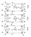
- FIG. 1a shows, in a highly schematic partial view, a door arrangement for closing a housing opening.
- a door leaf 14 made of sheet steel a left hinge 16a is formed on the left stop side 12a.
- the left hinge 16a has a door pivot 14 connected to the vertically upwardly facing upper left pivot pin 18a, which is in an upper left pivot pin receptacle 20a on the housing 22 is engaged and rotatably supported.
- the left hinge has a connected to the door leaf 14, pointing vertically downwards lower left pivot pin 24a, which is in a lower left pivot pin receptacle 26a on the housing 22 is engaged and rotatably supported.
- a right stop side 12b is additionally arranged, on which a right hinge 16b is formed.
- the right hinge has a vertically upwardly facing upper right pivot pin 18b connected to the door panel 14, which engages and is rotatably supported in an upper right pivot receptacle 20b on the housing 22.
- the right hinge 16b has a lower right pivot pin 24b connected to the door leaf 14 and pointing vertically downwardly, which engages in a lower right pivot pin receptacle 26b on the housing 22 and is rotatably supported.
- the housing 22 adjacent to the door leaf 14 has perpendicular to the pivot pins 18a, 18b, 24a and 24b extending housing parts 22a and 22b, in which the pivot pin receptacles 20a, 20b, 26a and 26b are formed as circular recesses.
- the housing parts 22a and 22b extending perpendicularly to the pivot pins 18a, 18b, 24a and 24b are made of sheet metal, in which the pivot pin receptacles 20a, 20b, 26a and 26b are formed as bores.
- an actuator 28 is arranged with an actuating handle 40 which is coupled to the left pivot pin 18 a, 24 a and the right pivot pin 18 b, 24 b and in the illustration of FIG. 1 a in the operating position "closed” or position 1 (POS1) is brought.
- the Figure 1 b shows a highly schematic partial view of a door assembly in which the actuator 28 is brought into the operating position "opening the left stop” and in the position 2 (POS2).
- POS2 the left opening stop operating position
- the left pivot pins 18a and 24a are disengaged from the left pivot pin seats 20a and 26a and the door panel 14 pivots about the right hinge 16b.
- the Figure 1c shows a highly schematic partial view of a door assembly in which the actuator 28 is brought into the operating position "opening the right stop” and in the position 3 (POS3).
- the right pivot pins 18b and 24b are disengaged from the right pivot pin seats 18b and 24b, and the door panel 14 can pivot about the left hinge 16a.
- FIGS. 1a to 1c clearly show, form the left and right hinges 16a and 16b together with the actuator 28, a locking mechanism which forms depending on the operating position POS1, POS2 or POS3 of the actuating element 28 on one or both stop sides 12a and 12b of the door leaf 14, a hinge or a closure.
- the closure may be placed on a door, wall or lid whose mechanism is constructed to have at least the three operating positions POS1, POS2 or POS3.
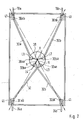
- FIG. 2 shows a schematic frontal view of the user facing away from the side of the door leaf 14 with an array of four actuating rods 30a, 30b, 32a and 32b, at its one end 30ab, 30bb, 32ab, 32bb with the associated pivot pin receptacles 20a, 20b, 26a, 26b remote end portions of the pivot pins 18a, 18b, 24a, 24b are connected.
- the actuating rods 30a, 30b, 32a and 32b are pivotally mounted on the lever arm H.
- the actuating rods 30a, 30b, 32a, 32b are formed of metal integrally with the pivot pins 18a, 18b, 24a, 24b.
- pivot pins 18a, 18b, 24a, 24b can also be actuated via a cable pull system.
- the actuator 28 has a rotatable about the axis A disc 38, on which the pivot pins 18a, 18b, 24a, 24b opposite ends 30aa, 30ba, 32aa, 32ba of the actuating rods 30a, 30b, 32a, 32b in a lever arm H accordingly Distance to the axis A in each case at bearing points L1, L2, L3, L4 attack.
- the rotatable disc 38 is arranged on the side facing away from the user of the door leaf 14 and parallel to the door leaf 14.
- the axle A connected to the rotatable disc 38 extends through the door panel 14 toward the user.
- the actuating element 28 has an actuating handle 40, as it is for example in the FIGS. 1a to 1c is shown.
- the bearing points L1, L2, L3 and L4 for the actuating means 30a, 30b, 32a and 32b are arranged on both sides of the rotatable disc 38.
- the bearing point L1 for the actuating means 30a connected to the upper left pivot pin 18a and the pivot point L4 for the actuating means 32b connected to the lower right pivot pin 24b are arranged on one side of the rotatable disc 38.
- the bearing point L2 for the actuating means 30b connected to the upper right pivot pin 18b and the pivot point L3 for the actuating means 32a connected to the lower left pivot pin 24a are arranged on the other side of the rotatable disc 38.
- a locking device is arranged, which may be formed in different embodiments and based of the FIGS. 3 to 13 will be described in more detail.
- the function of the locking means 41 acting on the upper left pivot pin 18a will be explained.
- the locking devices 41 arranged on the remaining pivot pins 18b, 24a and 24b are all of the same design.
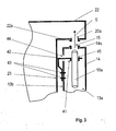
- FIG. 3 shows a schematic side view of a closed door 14 with a hinge assembly.
- the door is formed as a metal door with a door inner space 13a defined by the door leaf.
- the in the FIGS. 1a to 1c and 2 shown upper left pintle 18a can from a retracted position, as shown in the FIG. 3 is shown and in which the pivot pin 18a is not engaged with the pivot pin receptacle 20a, brought by vertical displacement in the direction of the arrow S in a (not shown) extended position.
- the pivot pin 18a can be moved through a pivot pin bushing 15 on the door edge 14a, which faces the housing part 22a extending perpendicular to the pivot pin 18a, in the direction of the pivot pin receptacle 20a which is aligned with the pivot pin bushing 15.
- the pivot pin 18a In the extended position then the pivot pin 18a is in engagement with the pivot pin receptacle 20a and is rotatably supported in this.
- the shift takes place when the in the FIGS. 1a to 1c and 2 shown actuator 28 and the rotatable disc 38 by the (not shown) actuating rod 30 a.
- the locking device has a securing spring 42, which is formed as a metal spring made of a metal sheet.
- the locking spring 42 is on one side on the housing wall 23 facing outside 13b of the door 14 by a screw 43 or by rivets attached.
- the door 14 has on the housing wall 23 side facing an opening 44 to the door interior 13a down.
- the securing spring 42 extends in the direction of the housing wall 23, then runs along the housing wall 23 and then extends at a right angle into the door interior 13a.
- the locking spring 42 is pressed by the housing wall 23 in the direction of the door interior 13 a and held under tension.
- the locking device is shown in its unlocked position.
- the extending in the door interior 13a part of the securing spring 42 has a perpendicular to the pivot pin 18a extending through hole 45, through which the pivot pin 18a extends.
- the through hole 45 is aligned in the in FIG. 3 shown entsprerrten position of the locking device 41 with the pivot pin passage 15 and the pivot pin receptacle 20a.
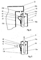
- FIG. 4 shows a schematic side view and in section the arrangement according to the FIG. 3 , wherein the door 14 is opened and the locking device 41 is locked.
- the locking spring 42 is effective between the door 14 and the pivot pin 18a and acts in the locked position of the locking device 41 laterally on the pivot pin 18a.
- the housing wall 23, the backup spring 42 no longer pushes in the direction of the door interior 13a and holds under tension, can spring 42 relax.
- the securing spring 42 shifts the pivot pin 18a in the locking position of the locking device 41 laterally such that the direction of displacement S of the pivot pin 18a points to an area 49 of the door 14 which adjoins the pivot pin bushing 15.
- the pivot pin 18 a strikes in the direction of displacement S at this area 49 and can not be passed through the pivot bolt lead-through 15.
- the pivot pin 18a is locked in its retracted position.
- the lower left pintle 24a shown in Figures la to le and 2 is also locked in its retracted position in the same manner.
- the formed on the left stop side 12a hinge 16a serves as an open lock. In this position, since the operating lever 40 is in the "right-stop opening operation position" (POS3), the hinge 16b at the right-hand stop side 12b is closed.
- FIG. 5 shows a schematic side view and in section the hinge assembly according to the Figures 3 and 4 with the door open.
- the locking spring 42 can be actuated by direct manual force in the direction K against its bias, causing the locking device 41 is brought back into its unlocked position.
- FIG. 6 shows a schematic side view and in section a closed door 14 with a not belonging to the invention embodiment of a hinge assembly.
- a securing spring 54 is effective, which has a perpendicular to the pivot pin 18a between this and the pivot pin passage 15 arranged guide plate 56.
- the securing spring 54 is formed as a metal spring made of a metal sheet.
- the securing spring 54 is on one side to the housing wall 23 facing Outside 13b of the door 14 by a screw 43 or by rivets aubracht.
- the door 14 has on the housing wall 23 side facing an opening 44 to the door interior 13a down.
- the securing spring 54 extends in the direction of the housing wall 23, then runs along the housing wall 23 and then extends at right angles through the opening 44 into the door interior 13a.
- the extending in the door interior 13a part of the securing spring 54 is formed as a guide plate 56 and has a perpendicular to the pivot pin 18a extending through hole 58.
- the through hole 58 is aligned in the in FIG. 6 shown unlocked position of the locking device 41 with the pivot pin bushing 15 and the pivot pin receptacle 20a, so that can be moved through actuation of the actuating lever 40 of the pivot pin 18a through the through hole 58, the pivot pin bushing 15 and the pivot pin receptacle 20a.
- FIG. 7 shows a schematic side view and in section the arrangement according to the FIG. 6 , wherein the door 14 is opened and the locking device 41 is locked by the guide plate 56 covers the pivot pin passage 15 at the top 14 a of the door 14.
- the securing spring 54 moves the cover plate 56 in the locking position of the locking device 41 such that the direction of displacement S of the pivot pin 18a no longer points through the through hole 58, but on the underside of the cover plate 56th
- the pivot pin 18a beats in the direction of displacement S at the bottom of the Cover plate and can not be passed through the through hole 58.
- the pivot pin 18a is locked in its retracted position.
- FIG. 8 shows a schematic side view and in section the hinge assembly according to the FIGS. 6 and 7 .
- the safety spring 42 can be actuated by direct manual action of force in the direction K against its bias, whereby the locking device 41 is brought back into its unlocked position.
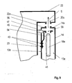
- FIG. 9 shows in a schematic side view and in section a closed door 14 with a hinge assembly according to another embodiment not belonging to the invention.
- the pivot pin 18a may be moved from a retracted position as shown in FIG FIG. 9 is shown and in which the pivot pin 18a is not engaged with the pivot pin receptacle 20a, are brought by vertical displacement in the direction of the arrow S in an extended position.
- the pivot pin 18a can be moved through a pivot pin bushing 15 on the door edge 14a, which faces the housing part 22a extending perpendicular to the pivot pin 18a, in the direction of the pivot pin receptacle 20a which is aligned with the pivot pin bushing 15.
- the pivot pin 18a In the extended position then the pivot pin 18a is in engagement with the pivot pin receptacle 20a and is rotatably supported in this.
- the locking device 41 On the pivot pin 18a is a releasable, spring-biased locking device 41 is effective.
- the locking device 41 has a securing spring 54, which is formed as a metal spring made of a metal sheet.
- the securing spring 54 is mounted in the door interior 13a on the side facing the housing wall 23 by a screw 43.
- the securing spring 54 extends in the direction of the door interior 13a, then extends parallel to the pivot pin 18a and then extends as a cover plate 56 at right angles to the pivot pin 18a.
- the cover plate 56 has a perpendicular to the pivot pin 18a extending through hole 58.
- the through hole 58 is aligned in the in FIG. 9 shown unlocked position of the locking device 41 with the pivot pin bushing 15 and the pivot pin receptacle 20a, so that can be moved through actuation of the actuating lever 40 of the pivot pin 18a through the through hole 58, the pivot pin bushing 15 and the pivot pin receptacle 20a.
- a mandrel 46 is arranged, which hineinerstreckt with the door 14 closed by an associated opening 47 in the door interior 13a and the locking spring 54 is actuated, whereby the locking device 41 is brought into its unlocked position.
- FIG. 10 shows a schematic side view and in section the arrangement according to the FIG. 9 , wherein the door 14 is opened and the locking device 41 is locked by the guide plate 56 covers the pivot pin passage 15 at the top 14 a of the door 14.
- the safety spring 54 no longer pushes in the direction of the door interior 13a and holds under tension, can fuse spring 54 relax.
- the securing spring 45 shifts the cover plate 56 in the locking position of the locking device 41 such that the direction of displacement S of the pivot pin 18a no longer points through the through hole 58, but on the underside of the cover plate 56.
- the pivot pin 18a suggests in the direction of displacement S at the bottom of Cover plate and can not be passed through the through hole 58.
- the pivot pin 18a is locked in its retracted position.
- FIG. 11 shows a schematic side view and in section the hinge assembly according to the Figures 9 and 10 .
- the locking spring 42 can be operated manually by introducing an actuating mandrel 48 in the opening 47 in the direction K against its bias, whereby the locking device 41 is brought back into its unlocked position.
- FIG. 12 shows a schematic side view and in section a closed door with a hinge assembly according to yet another embodiment.
- a releasable, spring-biased locking device 41 is effective on the pivot pin 18a.
- the locking device has a securing spring 42, which is formed as a metal spring made of a metal sheet.
- the securing spring 42 is mounted in the door interior 13 a on the housing wall 23 side facing by a screw 43.
- the securing spring 42 extends in the direction of the door interior 13a and subsequently extends parallel to the pivot pin 18a.
- an annular bolt guide 52 is arranged, in which the pivot pin 18 a is mounted.
- the bolt guide 52 is aligned in the in FIG. 12 shown unlocked position of the locking device 41 with the pivot pin bushing 15 and the pivot pin receptacle 20a, so that can be moved by actuation of the actuating lever 40 of the pivot pin 18a through the pivot pin passage 15 and the pivot pin receptacle 20a.
- a mandrel 46 is arranged, which hineinerstreckt with the door 14 closed by an associated opening 47 in the door interior 13a and the locking spring 42 is actuated, whereby the locking device 41 is brought into its unlocked position.
- FIG. 13 shows a schematic side view and in section the arrangement according to the FIG. 12 , wherein the door 14 is opened and the locking device 41 is locked.
- the securing spring 42 is effective between the door 14 and the pivot pin 18a and acts laterally on the pivot pin 18a via the pin guide 52 in the locked position of the locking device 41.
- the locking spring 42 no longer pushes in the direction of the door interior 13a and holds under tension, can spring 42 relax.
- the securing spring 42 shifts the pivot pin 18a laterally in the locking position of the locking device 41 in such a way that the direction of displacement S of the pivot pin 18a points to a region 49 of the door 14 adjacent to the pivot pin penetration 15.
- the pivot pin 18 a strikes in the direction of displacement S at this area 49 and can not be passed through the pivot bolt lead-through 15.
- the pivot pin 18a is locked in its retracted position.
Landscapes
- Engineering & Computer Science (AREA)
- Mechanical Engineering (AREA)
- Hinges (AREA)
- Closing And Opening Devices For Wings, And Checks For Wings (AREA)
- Patch Boards (AREA)
Claims (6)
- Porte métallique (14) comprenant un agencement à charnière pour la fermeture d'une ouverture de boîtier, la porte métallique (14) comprenant une chambre intérieure de porte (13a) délimitée par un ouvrant, l'agencement à charnière comprenant: au moins un pivot (18a, 18b, 24a, 24b) relié avec la porte (14), orienté perpendiculairement en direction du boîtier (22), qui peut être mis en prise avec un logement de pivot (20a, 20b, 26a, 26b) sur le boîtier (22), le pivot (18a) pouvant passer d'une position en retrait, à laquelle le pivot (18a) n'est pas en prise avec le logement de pivot (20a), par décalage vertical à une position déployée, à laquelle le pivot (18a) est en prise avec le logement de pivot (20a) et est monté pivotant dans celui-ci, un dispositif de verrouillage à ressort déverrouillable (41) agissant sur le pivot (18a), qui maintient le pivot (18a) à la position en retrait, le pivot (18a) pouvant être déplacé lorsque le dispositif de verrouillage (50) est détaché par un passage de pivot (15) sur l'arête de la porte orientée (14a) vers le boîtier (22) dans la direction du logement de pivot (20a) aligné avec le passage de pivot (15),
un ressort d'arrêt (42) agissant entre la porte métallique (14) et le pivot (18a), qui entre en prise latéralement avec le pivot (18a) et décale celui-ci latéralement à la position de verrouillage du dispositif de verrouillage (41), la direction de décalage verticale (S) du pivot (18a) étant orientée vers la région de la porte métallique (14) adjacente au passage de pivot (15), de manière à ce que le pivot (18a) ne puisse pas traverser le passage de pivot (15),
caractérisée en ce que
le ressort d'arrêt (42) est appliqué sur le côté extérieur (13b) de la porte métallique (14) orienté vers la paroi du boîtier (23) et avance dans la chambre intérieure de porte (13a) par une ouverture correspondante (44) de ce côté extérieur (13b) de la porte métallique (14) et agit sur le pivot (18a) de manière à ce qu'une partie du ressort d'arrêt (42) étendue dans la chambre intérieure de porte (13a) présente un alésage de passage (45) perpendiculaire au pivot (18a), au travers duquel le pivot (18a) s'étend. - Porte métallique (14) comprenant un agencement à charnière selon la revendication 1, caractérisée en ce que le ressort d'arrêt (42) peut être actionné contre sa prétension, le dispositif de verrouillage (41) pouvant ainsi être mis en sa position déverrouillée.
- Porte métallique (14) comprenant un agencement à charnière selon la revendication 1 ou 2, caractérisée en ce que le ressort d'arrêt (42) est configuré sous la forme d'un ressort métallique en une tôle métallique.
- Porte métallique (14) comprenant un agencement à charnière selon l'une quelconque des revendications 1 à 3, caractérisée en ce que le ressort d'arrêt (42) dépasse de la porte métallique (14) dans la direction de la paroi du boîtier (23) et est actionné par la paroi du boîtier (23) lorsque la porte métallique (14) est fermée, le dispositif de verrouillage (41) étant ainsi mis à sa position déverrouillée.
- Porte métallique (14) comprenant un agencement à charnière selon l'une quelconque des revendications 1 à 4, caractérisée en ce que le ressort d'arrêt (42) est directement actionnable manuellement lorsque la porte métallique (14) est ouverte, de manière à ce que le dispositif de verrouillage (41) soit mis à sa position déverrouillée.
- Porte métallique (14) comprenant un agencement à charnière selon l'une quelconque des revendications 1 à 3, caractérisée en ce que le pivot (18a) est placé dans un guide de goujon (52), le ressort d'arrêt (42) étant en prise avec le guide de goujon (52).
Applications Claiming Priority (2)
| Application Number | Priority Date | Filing Date | Title |
|---|---|---|---|
| DE102007017916A DE102007017916B3 (de) | 2007-04-13 | 2007-04-13 | Scharnieranordnung |
| PCT/EP2008/002784 WO2008125252A1 (fr) | 2007-04-13 | 2008-04-09 | Agencement de charnière |
Publications (2)
| Publication Number | Publication Date |
|---|---|
| EP2147178A1 EP2147178A1 (fr) | 2010-01-27 |
| EP2147178B1 true EP2147178B1 (fr) | 2014-02-26 |
Family
ID=39339202
Family Applications (1)
| Application Number | Title | Priority Date | Filing Date |
|---|---|---|---|
| EP08735100.3A Not-in-force EP2147178B1 (fr) | 2007-04-13 | 2008-04-09 | Agencement de charnière |
Country Status (5)
| Country | Link |
|---|---|
| US (1) | US8136203B2 (fr) |
| EP (1) | EP2147178B1 (fr) |
| CN (1) | CN101657596A (fr) |
| DE (1) | DE102007017916B3 (fr) |
| WO (1) | WO2008125252A1 (fr) |
Families Citing this family (11)
| Publication number | Priority date | Publication date | Assignee | Title |
|---|---|---|---|---|
| CN102191897B (zh) * | 2010-03-17 | 2015-03-25 | 上海贝尔股份有限公司 | 门铰链装置以及装有所述门铰链装置的门装置 |
| DE102010050965A1 (de) | 2010-05-21 | 2011-11-24 | Fujitsu Technology Solutions Intellectual Property Gmbh | Türanordnung für einen Geräteschrank und Verfahren zum Ändern einer Anschlagsseite einer Türanordnung |
| US8820861B2 (en) * | 2010-12-23 | 2014-09-02 | Lg Electronics Inc. | Laundry treating apparatus |
| KR101821208B1 (ko) * | 2011-12-21 | 2018-01-23 | 엘지전자 주식회사 | 의류처리장치 |
| US8936330B2 (en) | 2010-12-23 | 2015-01-20 | Lg Electronics Inc. | Laundry treating apparatus |
| KR102169956B1 (ko) | 2014-02-18 | 2020-10-26 | 엘지전자 주식회사 | 의류처리장치 |
| KR102169954B1 (ko) | 2014-02-18 | 2020-10-26 | 엘지전자 주식회사 | 의류처리장치 |
| KR102169955B1 (ko) | 2014-02-18 | 2020-10-26 | 엘지전자 주식회사 | 의류처리장치 |
| KR101653314B1 (ko) * | 2014-09-17 | 2016-09-01 | 엘지전자 주식회사 | 의류처리장치 |
| KR101653313B1 (ko) | 2014-09-17 | 2016-09-01 | 엘지전자 주식회사 | 의류처리장치 |
| US9234375B1 (en) * | 2014-10-06 | 2016-01-12 | Chin-Hsing Horng | Hinge structure with male shaft position adjustability |
Family Cites Families (14)
| Publication number | Priority date | Publication date | Assignee | Title |
|---|---|---|---|---|
| US2160330A (en) * | 1935-01-30 | 1939-05-30 | Pintsch Julius Kg | Door mounting and latching means |
| US2195991A (en) * | 1939-09-06 | 1940-04-02 | M S De Roy | Door mounting and latching means |
| US2660752A (en) * | 1948-08-27 | 1953-12-01 | Carcereny Juan Juncadella | Combined hinge and latch for doors |
| US2650388A (en) * | 1950-08-01 | 1953-09-01 | White William John | Hinging means |
| GB726711A (en) | 1953-04-08 | 1955-03-23 | Homer Harrison Cohun | Double acting door mounting |
| US3030656A (en) * | 1959-05-14 | 1962-04-24 | Westinghouse Electric Corp | Door mounting |
| DE3111595A1 (de) * | 1981-03-24 | 1982-10-28 | Mukai, Taichi | Im eingebauten zustand wahlweise beliebig oft links oder rechts anschlagbare tuer |
| DE69312134T2 (de) * | 1992-03-25 | 1997-12-11 | Kato Hatsujo Kaisha Ltd | Vorrichtung zum Öffnen und Schliessen eines Deckels |
| GB2266919A (en) | 1992-05-11 | 1993-11-17 | Thomas William Patric Sheppard | Hinging catch. |
| ES1024043Y (es) * | 1993-03-16 | 1994-04-01 | Domingo Ribot | Bisagra perfeccionada. |
| JP3748685B2 (ja) * | 1997-11-10 | 2006-02-22 | 有限会社愛和ライト | 扉操作機構 |
| JP4699600B2 (ja) * | 2000-01-11 | 2011-06-15 | 大阪金具株式会社 | 蝶番 |
| KR20060020079A (ko) * | 2004-08-31 | 2006-03-06 | 엘지전자 주식회사 | 냉장고 도어의 개폐장치 |
| DE102007012980B4 (de) | 2007-03-14 | 2016-03-31 | Rittal Rcs Communication Systems Gmbh & Co. Kg | Türanordnung zum Verschließen einer Gehäuseöffnung |
-
2007
- 2007-04-13 DE DE102007017916A patent/DE102007017916B3/de not_active Expired - Fee Related
-
2008
- 2008-04-09 EP EP08735100.3A patent/EP2147178B1/fr not_active Not-in-force
- 2008-04-09 CN CN200880011980A patent/CN101657596A/zh active Pending
- 2008-04-09 US US12/450,822 patent/US8136203B2/en not_active Expired - Fee Related
- 2008-04-09 WO PCT/EP2008/002784 patent/WO2008125252A1/fr active Application Filing
Also Published As
| Publication number | Publication date |
|---|---|
| US8136203B2 (en) | 2012-03-20 |
| US20100175221A1 (en) | 2010-07-15 |
| DE102007017916B3 (de) | 2008-06-05 |
| WO2008125252A1 (fr) | 2008-10-23 |
| CN101657596A (zh) | 2010-02-24 |
| EP2147178A1 (fr) | 2010-01-27 |
Similar Documents
| Publication | Publication Date | Title |
|---|---|---|
| EP2147178B1 (fr) | Agencement de charnière | |
| DE102012111397B4 (de) | Motorhaubenverriegelungsvorrichtung mit Zwei-Stufen-Führung für ein Fahrzeug | |
| DE3447748C2 (fr) | ||
| DE102005034833A1 (de) | Verschluß mit Ratschenklinke | |
| DE112004001383T5 (de) | Zwei-Richtungs-Öffnungsmechanismus für eine Tür | |
| DE3231417A1 (de) | Verschliessbarer behaelter nach der art eines koffers, schrankes oder dergleichen | |
| DE102007012980B4 (de) | Türanordnung zum Verschließen einer Gehäuseöffnung | |
| EP3175068B1 (fr) | Système de ferrure | |
| DE102011085177B4 (de) | Antriebssystem für ein KFZ-Dachsystem | |
| DE202005000064U1 (de) | Band für eine verdeckte Anordnung zwischen Zarge und Flügel | |
| DE102006021636B3 (de) | Schließvorrichtung | |
| DE2043780B2 (de) | Innenverriegelungseinrichtung für einen Kraftfahrzeug-Türverschluß | |
| DE3152291C2 (fr) | ||
| DE202008011372U1 (de) | Dämpfungsvorrichtung | |
| DE102009031686B4 (de) | Schubladenfront mit Verschließmechanismus zum Verriegeln von Schubladen in Fahrzeugen | |
| DE102006018485A1 (de) | Gelenkanordnung zum Betätigen einer Klappe, insbesondere Rauchabzugsklappe | |
| CH622575A5 (fr) | ||
| EP3183408B1 (fr) | Élément de commande pour système de ferrure | |
| DE19902579C2 (de) | Verschlußvorrichtung für den unterschlagenden Flügel zweiflügeliger setzholzloser Fenster oder Türen | |
| CH714076A1 (de) | Maschinenverkleidung. | |
| DE102014007197B4 (de) | Getriebe für Paniktürverschluss | |
| CH665873A5 (de) | Scharnier zum beweglichen verbinden zweier teile, insbesondere fuer kuehlschraenke. | |
| DE102009049814B4 (de) | Scharnier | |
| DE102008028598A1 (de) | Insektenschutztür | |
| DE2718439C2 (fr) |
Legal Events
| Date | Code | Title | Description |
|---|---|---|---|
| PUAI | Public reference made under article 153(3) epc to a published international application that has entered the european phase |
Free format text: ORIGINAL CODE: 0009012 |
|
| 17P | Request for examination filed |
Effective date: 20091113 |
|
| AK | Designated contracting states |
Kind code of ref document: A1 Designated state(s): AT BE BG CH CY CZ DE DK EE ES FI FR GB GR HR HU IE IS IT LI LT LU LV MC MT NL NO PL PT RO SE SI SK TR |
|
| AX | Request for extension of the european patent |
Extension state: AL BA MK RS |
|
| DAX | Request for extension of the european patent (deleted) | ||
| 17Q | First examination report despatched |
Effective date: 20101103 |
|
| GRAP | Despatch of communication of intention to grant a patent |
Free format text: ORIGINAL CODE: EPIDOSNIGR1 |
|
| INTG | Intention to grant announced |
Effective date: 20131015 |
|
| GRAS | Grant fee paid |
Free format text: ORIGINAL CODE: EPIDOSNIGR3 |
|
| GRAA | (expected) grant |
Free format text: ORIGINAL CODE: 0009210 |
|
| AK | Designated contracting states |
Kind code of ref document: B1 Designated state(s): AT BE BG CH CY CZ DE DK EE ES FI FR GB GR HR HU IE IS IT LI LT LU LV MC MT NL NO PL PT RO SE SI SK TR |
|
| REG | Reference to a national code |
Ref country code: GB Ref legal event code: FG4D Free format text: NOT ENGLISH |
|
| REG | Reference to a national code |
Ref country code: CH Ref legal event code: EP |
|
| REG | Reference to a national code |
Ref country code: AT Ref legal event code: REF Ref document number: 653726 Country of ref document: AT Kind code of ref document: T Effective date: 20140315 |
|
| REG | Reference to a national code |
Ref country code: IE Ref legal event code: FG4D Free format text: LANGUAGE OF EP DOCUMENT: GERMAN |
|
| REG | Reference to a national code |
Ref country code: DE Ref legal event code: R096 Ref document number: 502008011349 Country of ref document: DE Effective date: 20140410 |
|
| REG | Reference to a national code |
Ref country code: NL Ref legal event code: VDEP Effective date: 20140226 |
|
| REG | Reference to a national code |
Ref country code: LT Ref legal event code: MG4D |
|
| PG25 | Lapsed in a contracting state [announced via postgrant information from national office to epo] |
Ref country code: IS Free format text: LAPSE BECAUSE OF FAILURE TO SUBMIT A TRANSLATION OF THE DESCRIPTION OR TO PAY THE FEE WITHIN THE PRESCRIBED TIME-LIMIT Effective date: 20140626 Ref country code: LT Free format text: LAPSE BECAUSE OF FAILURE TO SUBMIT A TRANSLATION OF THE DESCRIPTION OR TO PAY THE FEE WITHIN THE PRESCRIBED TIME-LIMIT Effective date: 20140226 Ref country code: NO Free format text: LAPSE BECAUSE OF FAILURE TO SUBMIT A TRANSLATION OF THE DESCRIPTION OR TO PAY THE FEE WITHIN THE PRESCRIBED TIME-LIMIT Effective date: 20140526 |
|
| PG25 | Lapsed in a contracting state [announced via postgrant information from national office to epo] |
Ref country code: NL Free format text: LAPSE BECAUSE OF FAILURE TO SUBMIT A TRANSLATION OF THE DESCRIPTION OR TO PAY THE FEE WITHIN THE PRESCRIBED TIME-LIMIT Effective date: 20140226 Ref country code: FI Free format text: LAPSE BECAUSE OF FAILURE TO SUBMIT A TRANSLATION OF THE DESCRIPTION OR TO PAY THE FEE WITHIN THE PRESCRIBED TIME-LIMIT Effective date: 20140226 Ref country code: CY Free format text: LAPSE BECAUSE OF FAILURE TO SUBMIT A TRANSLATION OF THE DESCRIPTION OR TO PAY THE FEE WITHIN THE PRESCRIBED TIME-LIMIT Effective date: 20140226 Ref country code: SE Free format text: LAPSE BECAUSE OF FAILURE TO SUBMIT A TRANSLATION OF THE DESCRIPTION OR TO PAY THE FEE WITHIN THE PRESCRIBED TIME-LIMIT Effective date: 20140226 Ref country code: PT Free format text: LAPSE BECAUSE OF FAILURE TO SUBMIT A TRANSLATION OF THE DESCRIPTION OR TO PAY THE FEE WITHIN THE PRESCRIBED TIME-LIMIT Effective date: 20140626 |
|
| PG25 | Lapsed in a contracting state [announced via postgrant information from national office to epo] |
Ref country code: LV Free format text: LAPSE BECAUSE OF FAILURE TO SUBMIT A TRANSLATION OF THE DESCRIPTION OR TO PAY THE FEE WITHIN THE PRESCRIBED TIME-LIMIT Effective date: 20140226 Ref country code: HR Free format text: LAPSE BECAUSE OF FAILURE TO SUBMIT A TRANSLATION OF THE DESCRIPTION OR TO PAY THE FEE WITHIN THE PRESCRIBED TIME-LIMIT Effective date: 20140226 |
|
| PG25 | Lapsed in a contracting state [announced via postgrant information from national office to epo] |
Ref country code: EE Free format text: LAPSE BECAUSE OF FAILURE TO SUBMIT A TRANSLATION OF THE DESCRIPTION OR TO PAY THE FEE WITHIN THE PRESCRIBED TIME-LIMIT Effective date: 20140226 Ref country code: CZ Free format text: LAPSE BECAUSE OF FAILURE TO SUBMIT A TRANSLATION OF THE DESCRIPTION OR TO PAY THE FEE WITHIN THE PRESCRIBED TIME-LIMIT Effective date: 20140226 Ref country code: DK Free format text: LAPSE BECAUSE OF FAILURE TO SUBMIT A TRANSLATION OF THE DESCRIPTION OR TO PAY THE FEE WITHIN THE PRESCRIBED TIME-LIMIT Effective date: 20140226 Ref country code: RO Free format text: LAPSE BECAUSE OF FAILURE TO SUBMIT A TRANSLATION OF THE DESCRIPTION OR TO PAY THE FEE WITHIN THE PRESCRIBED TIME-LIMIT Effective date: 20140226 |
|
| REG | Reference to a national code |
Ref country code: DE Ref legal event code: R119 Ref document number: 502008011349 Country of ref document: DE |
|
| PG25 | Lapsed in a contracting state [announced via postgrant information from national office to epo] |
Ref country code: PL Free format text: LAPSE BECAUSE OF FAILURE TO SUBMIT A TRANSLATION OF THE DESCRIPTION OR TO PAY THE FEE WITHIN THE PRESCRIBED TIME-LIMIT Effective date: 20140226 Ref country code: LU Free format text: LAPSE BECAUSE OF FAILURE TO SUBMIT A TRANSLATION OF THE DESCRIPTION OR TO PAY THE FEE WITHIN THE PRESCRIBED TIME-LIMIT Effective date: 20140409 Ref country code: SK Free format text: LAPSE BECAUSE OF FAILURE TO SUBMIT A TRANSLATION OF THE DESCRIPTION OR TO PAY THE FEE WITHIN THE PRESCRIBED TIME-LIMIT Effective date: 20140226 Ref country code: ES Free format text: LAPSE BECAUSE OF FAILURE TO SUBMIT A TRANSLATION OF THE DESCRIPTION OR TO PAY THE FEE WITHIN THE PRESCRIBED TIME-LIMIT Effective date: 20140226 Ref country code: MC Free format text: LAPSE BECAUSE OF FAILURE TO SUBMIT A TRANSLATION OF THE DESCRIPTION OR TO PAY THE FEE WITHIN THE PRESCRIBED TIME-LIMIT Effective date: 20140226 |
|
| REG | Reference to a national code |
Ref country code: CH Ref legal event code: PL |
|
| PLBE | No opposition filed within time limit |
Free format text: ORIGINAL CODE: 0009261 |
|
| STAA | Information on the status of an ep patent application or granted ep patent |
Free format text: STATUS: NO OPPOSITION FILED WITHIN TIME LIMIT |
|
| REG | Reference to a national code |
Ref country code: DE Ref legal event code: R119 Ref document number: 502008011349 Country of ref document: DE Effective date: 20141101 |
|
| REG | Reference to a national code |
Ref country code: FR Ref legal event code: ST Effective date: 20141231 |
|
| GBPC | Gb: european patent ceased through non-payment of renewal fee |
Effective date: 20140526 |
|
| REG | Reference to a national code |
Ref country code: IE Ref legal event code: MM4A |
|
| PG25 | Lapsed in a contracting state [announced via postgrant information from national office to epo] |
Ref country code: CH Free format text: LAPSE BECAUSE OF NON-PAYMENT OF DUE FEES Effective date: 20140430 Ref country code: DE Free format text: LAPSE BECAUSE OF NON-PAYMENT OF DUE FEES Effective date: 20141101 Ref country code: LI Free format text: LAPSE BECAUSE OF NON-PAYMENT OF DUE FEES Effective date: 20140430 |
|
| 26N | No opposition filed |
Effective date: 20141127 |
|
| PG25 | Lapsed in a contracting state [announced via postgrant information from national office to epo] |
Ref country code: FR Free format text: LAPSE BECAUSE OF NON-PAYMENT OF DUE FEES Effective date: 20140430 |
|
| PG25 | Lapsed in a contracting state [announced via postgrant information from national office to epo] |
Ref country code: IT Free format text: LAPSE BECAUSE OF FAILURE TO SUBMIT A TRANSLATION OF THE DESCRIPTION OR TO PAY THE FEE WITHIN THE PRESCRIBED TIME-LIMIT Effective date: 20140226 |
|
| PG25 | Lapsed in a contracting state [announced via postgrant information from national office to epo] |
Ref country code: IE Free format text: LAPSE BECAUSE OF NON-PAYMENT OF DUE FEES Effective date: 20140409 |
|
| PG25 | Lapsed in a contracting state [announced via postgrant information from national office to epo] |
Ref country code: GB Free format text: LAPSE BECAUSE OF NON-PAYMENT OF DUE FEES Effective date: 20140526 Ref country code: SI Free format text: LAPSE BECAUSE OF FAILURE TO SUBMIT A TRANSLATION OF THE DESCRIPTION OR TO PAY THE FEE WITHIN THE PRESCRIBED TIME-LIMIT Effective date: 20140226 |
|
| REG | Reference to a national code |
Ref country code: AT Ref legal event code: MM01 Ref document number: 653726 Country of ref document: AT Kind code of ref document: T Effective date: 20140409 |
|
| PG25 | Lapsed in a contracting state [announced via postgrant information from national office to epo] |
Ref country code: AT Free format text: LAPSE BECAUSE OF NON-PAYMENT OF DUE FEES Effective date: 20140409 |
|
| PG25 | Lapsed in a contracting state [announced via postgrant information from national office to epo] |
Ref country code: MT Free format text: LAPSE BECAUSE OF FAILURE TO SUBMIT A TRANSLATION OF THE DESCRIPTION OR TO PAY THE FEE WITHIN THE PRESCRIBED TIME-LIMIT Effective date: 20140226 |
|
| PG25 | Lapsed in a contracting state [announced via postgrant information from national office to epo] |
Ref country code: BG Free format text: LAPSE BECAUSE OF FAILURE TO SUBMIT A TRANSLATION OF THE DESCRIPTION OR TO PAY THE FEE WITHIN THE PRESCRIBED TIME-LIMIT Effective date: 20140226 |
|
| PG25 | Lapsed in a contracting state [announced via postgrant information from national office to epo] |
Ref country code: GR Free format text: LAPSE BECAUSE OF FAILURE TO SUBMIT A TRANSLATION OF THE DESCRIPTION OR TO PAY THE FEE WITHIN THE PRESCRIBED TIME-LIMIT Effective date: 20140527 |
|
| PG25 | Lapsed in a contracting state [announced via postgrant information from national office to epo] |
Ref country code: BE Free format text: LAPSE BECAUSE OF FAILURE TO SUBMIT A TRANSLATION OF THE DESCRIPTION OR TO PAY THE FEE WITHIN THE PRESCRIBED TIME-LIMIT Effective date: 20140430 Ref country code: TR Free format text: LAPSE BECAUSE OF FAILURE TO SUBMIT A TRANSLATION OF THE DESCRIPTION OR TO PAY THE FEE WITHIN THE PRESCRIBED TIME-LIMIT Effective date: 20140226 Ref country code: HU Free format text: LAPSE BECAUSE OF FAILURE TO SUBMIT A TRANSLATION OF THE DESCRIPTION OR TO PAY THE FEE WITHIN THE PRESCRIBED TIME-LIMIT; INVALID AB INITIO Effective date: 20080409 |