EP2146411A2 - Couplage de barres collectrices pour une installation de commutation électrique - Google Patents
Couplage de barres collectrices pour une installation de commutation électrique Download PDFInfo
- Publication number
- EP2146411A2 EP2146411A2 EP09005971A EP09005971A EP2146411A2 EP 2146411 A2 EP2146411 A2 EP 2146411A2 EP 09005971 A EP09005971 A EP 09005971A EP 09005971 A EP09005971 A EP 09005971A EP 2146411 A2 EP2146411 A2 EP 2146411A2
- Authority
- EP
- European Patent Office
- Prior art keywords
- housing
- busbars
- coupling
- busbar
- metal strip
- Prior art date
- Legal status (The legal status is an assumption and is not a legal conclusion. Google has not performed a legal analysis and makes no representation as to the accuracy of the status listed.)
- Withdrawn
Links
Images
Classifications
-
- H—ELECTRICITY
- H02—GENERATION; CONVERSION OR DISTRIBUTION OF ELECTRIC POWER
- H02B—BOARDS, SUBSTATIONS OR SWITCHING ARRANGEMENTS FOR THE SUPPLY OR DISTRIBUTION OF ELECTRIC POWER
- H02B13/00—Arrangement of switchgear in which switches are enclosed in, or structurally associated with, a casing, e.g. cubicle
- H02B13/005—Electrical connection between switchgear cells
Definitions
- the invention relates to a busbar coupling for an electrical switchgear according to the preamble of claim 1.
- An electrical switchgear in particular in the region of the medium voltage, usually consists of a plurality of juxtaposed electrical switching units.
- the individual switching units each have a plurality of mostly superimposed functional modules.
- electrical switchgear such as circuit breakers or circuit breakers are often present in a central area, and in a lower portion of the switching unit sockets are provided, can be connected via the down in a channel outgoing cable.
- the juxtaposed switching units are usually electrically connected to each other via busbars.
- the busbars may be arranged within or above the switching units, in order then to be connected to one another and optionally to the switching units by means of a so-called busbar coupling.
- busbar coupling is from the DE 102 46 557 A1 known.
- Each of the two busbars projects out of a passageway of the associated switching unit.
- the bushings are made gas-tight and electrically insulating.
- the two bus bars are aligned coaxially with each other and connected to each other via an electrically conductive coupling.
- the object of the invention is to improve this known busbar coupling.
- the invention solves this problem by a busbar coupling for an electrical switchgear in particular for the range of medium voltage according to claim 1.
- a housing made of metal which has a cylindrical design, in each of whose two ends a busbar having a respective surrounding insulating sleeve is received.
- the two busbars are in the interior of the housing via a Metal band connected together and the housing is filled with an insulating material.
- the busbar coupling according to the invention is designed to be extremely stable on the one hand due to the metallic housing. This also allows a stable and therefore secure connection of the housing with the busbars to be connected. On the other hand, an extremely high dielectric strength of the busbar coupling according to the invention is achieved by the housing filled with the insulating material. Another advantage of the invention is its simple structure. In particular, a secure electrical connection between the two busbars can be achieved via the metal strip in a simple yet stable manner.
- the two busbars are gas-tight connected to the respectively associated sleeve and / or it is the two busbars together with the surrounding sleeves gas-tightly connected to the housing.
- the housing has an opening through which the metal strip can be inserted into the interior of the housing, and via which the insulating material in the interior of the housing can be filled.
- the opening is closed by a plate, which preferably has a lid with a material associated with the insulating bellows having.
- the housing is provided with a design in which a bushing is received, which is provided with an electrically conductive contact piece, which is connected to the metal strip.
- a connecting rail for a switching unit arranged below the busbar coupling can be connected to the busbars via the contact piece.
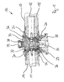
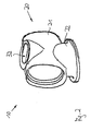
- FIG. 1 shows a schematic longitudinal section through an embodiment of a busbar coupling according to the invention for an electrical switchgear and FIG. 2 shows a schematic view of the busbar coupling of FIG. 1 ,
- busbar coupling 10 is assumed that two busbars 11, 12 of a medium-voltage electrical switchgear are arranged side by side. It is further assumed that the two busbars 11, 12 are made of an electrically conductive material and according to the FIG. 1 have a substantially circular cross-section. Again FIG. 1 can also be removed, each of the two busbars 11, 12 surrounded by a substantially tubular sleeve 14, 15 of electrically insulating material. The inner diameter of the sleeves 14, 15 and the outer diameter of the respective associated busbars 11, 12 are provided such that the sleeves 14, 15 abut gas-tight on the busbars 11, 12.
- the two bus bars 11, 12 together with the surrounding two sleeves 14, 15 are substantially coaxially aligned with each other and their free, facing ends are spaced from each other. Furthermore, the FIG. 1 can be taken that the two sleeves 14, 15 are provided on its outer surface with an electrically conductive layer 17. The conical end region of the two sleeves 14, 15 is not provided with the conductive layer. In this end region, the two sleeves 14, 15 have a field control in the form of a cast-in grid or the like.
- the busbar clutch 10 of FIGS. 1 and 2 has a housing 20 which has a shape which is illustratively comparable to two approximately transversely aligned and interpenetrating cylinders 21,22.
- the first cylinder 21 is for receiving the two Busbars 11, 12 provided with the two sleeves 14, 15 and has an inner diameter which corresponds substantially to the outer diameter of the two sleeves 14, 15.
- the second cylinder 22 has a similar diameter as the first cylinder 21 and is provided, inter alia, for access to the interior of the housing 20.
- the two busbars 11, 12 in their coaxial orientation and with their respective surrounding sleeves 14, 15 are inserted from both sides at least slightly into the two ends of the first cylinder 21 of the housing 20.
- a ring seal 24 is present between the housing 20 and each of the two sleeves 14, 15 each for the purpose of gas-tight seal.
- the two bus bars 11, 12 in the interior of the housing 20 via a particular flexible metal strip 26 are electrically connected together.
- the metal strip 26 is screwed to the end face of each of the two busbars 11, 12.
- the second cylinder 22 of the housing 20 is closed at its one end by means of an approximately pot-shaped passage 28.
- a ring seal 29 is present for gas-tight sealing between the outer edge of the bushing 28 and the housing 20, a ring seal 29 is present.
- the passage 28 is provided with an approximately coaxial with the cylinder 22 aligned, leading from the interior of the housing 20 to the outside opening in which a substantially cylindrical and electrically conductive contact piece 30 is received gas-tight.
- the facing the interior of the housing 20 end face of the contact piece 30 is electrically connected to the metal strip 26, in particular screwed.
- the outwardly facing end face of the contact piece 30 may be provided with an internal thread.
- the contact piece 30 can thus be mechanically and electrically connected to other electrical components.
- a connection rail may be connected to the contact piece 30, with which a switching unit of the electrical switchgear arranged below the busbar coupling 10 can be connected to the two busbars 11, 12.
- the cylinder 22 of the housing 20 is provided with an opening 32.
- the metal strip 26 can be inserted into the interior of the housing 20 through this opening 32. Furthermore, the metal strip 26 can then be screwed through this opening 32 with the two busbars 11, 12 and the contact piece 30.
- the housing 20 is made of an electrically conductive material, for example of a metal.
- the housing 20 may be made as a cast aluminum.
- the interior of the housing 20 is filled with an insulating material.
- the interior is filled with an insulating liquid or an insulating gel. This may be SF6, for example, in a liquid or gel form. This insulating material can be filled through the opening 32 in the interior of the housing 20.
- the opening 32 of the housing 20 is closed by a substantially circular plate 34.
- the plate 34 may be screwed in a manner not shown to the housing 20.
- a ring seal 36 Between the Plate 34 and the housing 20 is provided for gas-tight sealing a ring seal 36.
- the plate 34 is provided with a gas-tight plug-on or screw-on lid 38. With the lid 38 open, the presence and the amount of existing insulating material can be checked. Furthermore, 34 can be filled or refilled with the lid open insulating material in the interior of the housing 20.
- a flexible bellows 39 may be present, which is in the closed state of the lid 38 with the insulating material in contact. If now changes the volume of the insulating material, for example due to temperature fluctuations, this change is compensated by the bellows 39.
- the opening 32 may also be closed with a contact piece, to which in particular a voltage converter is connected.
- the contact piece can then be connected via a metal strip to the busbars 11, 12.
- busbar coupling 10 can also be designed for the connection of two or more busbars. It is also understood that on one side of the busbar coupling 10, instead of the existing busbar there may also be another electrical component, such as a current transformer or the like.
Applications Claiming Priority (1)
| Application Number | Priority Date | Filing Date | Title |
|---|---|---|---|
| DE200810033495 DE102008033495B4 (de) | 2008-07-16 | 2008-07-16 | Sammelschienenkupplung für eine elektrische Schaltanlage |
Publications (2)
| Publication Number | Publication Date |
|---|---|
| EP2146411A2 true EP2146411A2 (fr) | 2010-01-20 |
| EP2146411A3 EP2146411A3 (fr) | 2010-09-29 |
Family
ID=41268246
Family Applications (1)
| Application Number | Title | Priority Date | Filing Date |
|---|---|---|---|
| EP09005971A Withdrawn EP2146411A3 (fr) | 2008-07-16 | 2009-04-30 | Couplage de barres collectrices pour une installation de commutation électrique |
Country Status (2)
| Country | Link |
|---|---|
| EP (1) | EP2146411A3 (fr) |
| DE (1) | DE102008033495B4 (fr) |
Cited By (2)
| Publication number | Priority date | Publication date | Assignee | Title |
|---|---|---|---|---|
| CN107104336A (zh) * | 2017-06-06 | 2017-08-29 | 七星电气股份有限公司 | 一种母线连接器、开关柜、母线连接结构及组合柜 |
| CN110189872A (zh) * | 2019-05-13 | 2019-08-30 | 平高集团有限公司 | 一种固定式单支柱绝缘子、管道母线及其母线单元 |
Families Citing this family (2)
| Publication number | Priority date | Publication date | Assignee | Title |
|---|---|---|---|---|
| US9646793B2 (en) * | 2015-03-15 | 2017-05-09 | Schneider Electric USA, Inc. | Offset bus connection with field shaping and heat sink |
| DE102019200021B4 (de) * | 2019-01-03 | 2023-10-12 | Zf Friedrichshafen Ag | Kontaktierungsvorrichtung |
Citations (4)
| Publication number | Priority date | Publication date | Assignee | Title |
|---|---|---|---|---|
| US2469445A (en) * | 1944-03-25 | 1949-05-10 | Ite Circuit Breaker Ltd | Bus bar housing |
| GB1217810A (en) * | 1968-11-15 | 1970-12-31 | Sprecher & Schuh Ag | Improvements in or relating to electric high voltage conduit |
| GB1238293A (fr) * | 1967-07-21 | 1971-07-07 | ||
| DE3211119A1 (de) * | 1982-03-26 | 1983-10-06 | Pfisterer Elektrotech Karl | Vorrichtung zur herstellung einer elektrisch leitenden verbindung zwischen einer isolierten rohrsammelschiene und isolierten kabeln eines mittelspannungs- oder hochspannungsenergieversorgungssytems |
Family Cites Families (1)
| Publication number | Priority date | Publication date | Assignee | Title |
|---|---|---|---|---|
| DE10246557A1 (de) * | 2002-10-05 | 2004-04-15 | Alstom | Verbindungsmuffe für eine Sammelschienenkupplung in einer gasisolierten Schaltanlage |
-
2008
- 2008-07-16 DE DE200810033495 patent/DE102008033495B4/de not_active Expired - Fee Related
-
2009
- 2009-04-30 EP EP09005971A patent/EP2146411A3/fr not_active Withdrawn
Patent Citations (4)
| Publication number | Priority date | Publication date | Assignee | Title |
|---|---|---|---|---|
| US2469445A (en) * | 1944-03-25 | 1949-05-10 | Ite Circuit Breaker Ltd | Bus bar housing |
| GB1238293A (fr) * | 1967-07-21 | 1971-07-07 | ||
| GB1217810A (en) * | 1968-11-15 | 1970-12-31 | Sprecher & Schuh Ag | Improvements in or relating to electric high voltage conduit |
| DE3211119A1 (de) * | 1982-03-26 | 1983-10-06 | Pfisterer Elektrotech Karl | Vorrichtung zur herstellung einer elektrisch leitenden verbindung zwischen einer isolierten rohrsammelschiene und isolierten kabeln eines mittelspannungs- oder hochspannungsenergieversorgungssytems |
Cited By (2)
| Publication number | Priority date | Publication date | Assignee | Title |
|---|---|---|---|---|
| CN107104336A (zh) * | 2017-06-06 | 2017-08-29 | 七星电气股份有限公司 | 一种母线连接器、开关柜、母线连接结构及组合柜 |
| CN110189872A (zh) * | 2019-05-13 | 2019-08-30 | 平高集团有限公司 | 一种固定式单支柱绝缘子、管道母线及其母线单元 |
Also Published As
| Publication number | Publication date |
|---|---|
| DE102008033495B4 (de) | 2010-04-29 |
| DE102008033495A1 (de) | 2010-01-21 |
| EP2146411A3 (fr) | 2010-09-29 |
Similar Documents
| Publication | Publication Date | Title |
|---|---|---|
| EP2182602B1 (fr) | Dispositif destiné à une position de connexion entre deux câbles électriques haute tension | |
| EP3185365B1 (fr) | Rail d'alimentation | |
| DE102004046134A1 (de) | Freiluftendverschluss | |
| DE102008033495B4 (de) | Sammelschienenkupplung für eine elektrische Schaltanlage | |
| DE102007063478A1 (de) | Anordnung mit einer Sammelschiene | |
| EP4049344A1 (fr) | Boîtier, plus particulièrement boîtier de ligne, système, et procédé de production d'un système de ce type | |
| EP0678953B1 (fr) | Terminaison de câble pour un appareillage de commutation blindé métallique à haute tension et à isolement gazeux | |
| WO2013072153A1 (fr) | Commutateur électrique | |
| DE102008024142A1 (de) | Elektrische Schalteinheit für eine elektrische Schaltanlage insbesondere für den Bereich der Mittelspannung | |
| WO2018083295A1 (fr) | Système de ligne électrique blindé et boîtier de blindage | |
| DE19856025C2 (de) | Kompakte Übergangsmuffe | |
| DE102011005700A1 (de) | Elektrische Kontaktanordnung | |
| EP3076409B1 (fr) | Connexion électrique d'enroulements écartés les uns des autres | |
| EP2403087B1 (fr) | Arrangement pour relier deux câbles à haute tension isolés au papier | |
| DE10129568B4 (de) | Hochstromschiene | |
| DE1170501C2 (de) | Metallgekapselte Hochspannungsschaltanlage | |
| DE102017204930B4 (de) | Elektrisches Gerät zum Anschluss an ein Hochspannungsnetz | |
| DE19959450B4 (de) | Elektrische Steckverbindung, welche sich während der Montage der isoliergasbefüllten Schaltanlagenkomponenten selbsttätig mit Isoliergas befüllt | |
| DE102012203709A1 (de) | Hochspannungsdurchführung für Gleichspannung | |
| EP3685411B1 (fr) | Agencement d'enroulement | |
| WO2006084401A1 (fr) | Pole d'interrupteur | |
| CH675501A5 (en) | Gas insulated high voltage converter | |
| DE102009022103A1 (de) | Gasisolierte Hochspannungsschaltanlage | |
| EP1406364B1 (fr) | Dispositif de traversée haute tension avec plusieurs traversées | |
| DE102014012910A1 (de) | Hochfrequenz-Steckverbindungseinrichtung, insbesondere Koaxial-Steckverbindungseinrichtung für Antennensteckdosen |
Legal Events
| Date | Code | Title | Description |
|---|---|---|---|
| PUAI | Public reference made under article 153(3) epc to a published international application that has entered the european phase |
Free format text: ORIGINAL CODE: 0009012 |
|
| AK | Designated contracting states |
Kind code of ref document: A2 Designated state(s): AT BE BG CH CY CZ DE DK EE ES FI FR GB GR HR HU IE IS IT LI LT LU LV MC MK MT NL NO PL PT RO SE SI SK TR |
|
| AX | Request for extension of the european patent |
Extension state: AL BA RS |
|
| PUAL | Search report despatched |
Free format text: ORIGINAL CODE: 0009013 |
|
| AK | Designated contracting states |
Kind code of ref document: A3 Designated state(s): AT BE BG CH CY CZ DE DK EE ES FI FR GB GR HR HU IE IS IT LI LT LU LV MC MK MT NL NO PL PT RO SE SI SK TR |
|
| AX | Request for extension of the european patent |
Extension state: AL BA RS |
|
| STAA | Information on the status of an ep patent application or granted ep patent |
Free format text: STATUS: THE APPLICATION IS DEEMED TO BE WITHDRAWN |
|
| 18D | Application deemed to be withdrawn |
Effective date: 20110330 |