EP1406364B1 - Dispositif de traversée haute tension avec plusieurs traversées - Google Patents
Dispositif de traversée haute tension avec plusieurs traversées Download PDFInfo
- Publication number
- EP1406364B1 EP1406364B1 EP20030090292 EP03090292A EP1406364B1 EP 1406364 B1 EP1406364 B1 EP 1406364B1 EP 20030090292 EP20030090292 EP 20030090292 EP 03090292 A EP03090292 A EP 03090292A EP 1406364 B1 EP1406364 B1 EP 1406364B1
- Authority
- EP
- European Patent Office
- Prior art keywords
- bushings
- arrangement
- voltage
- housing
- support plate
- Prior art date
- Legal status (The legal status is an assumption and is not a legal conclusion. Google has not performed a legal analysis and makes no representation as to the accuracy of the status listed.)
- Expired - Lifetime
Links
- 239000007789 gas Substances 0.000 description 5
- 239000004020 conductor Substances 0.000 description 4
- IJGRMHOSHXDMSA-UHFFFAOYSA-N Atomic nitrogen Chemical compound N#N IJGRMHOSHXDMSA-UHFFFAOYSA-N 0.000 description 2
- 238000009434 installation Methods 0.000 description 2
- 229910018503 SF6 Inorganic materials 0.000 description 1
- 230000000712 assembly Effects 0.000 description 1
- 238000000429 assembly Methods 0.000 description 1
- 238000010276 construction Methods 0.000 description 1
- 230000002950 deficient Effects 0.000 description 1
- 230000005684 electric field Effects 0.000 description 1
- 238000000034 method Methods 0.000 description 1
- 229910052757 nitrogen Inorganic materials 0.000 description 1
- 238000005192 partition Methods 0.000 description 1
- SFZCNBIFKDRMGX-UHFFFAOYSA-N sulfur hexafluoride Chemical compound FS(F)(F)(F)(F)F SFZCNBIFKDRMGX-UHFFFAOYSA-N 0.000 description 1
- 229960000909 sulfur hexafluoride Drugs 0.000 description 1
- 230000008719 thickening Effects 0.000 description 1
Images


Classifications
-
- H—ELECTRICITY
- H02—GENERATION; CONVERSION OR DISTRIBUTION OF ELECTRIC POWER
- H02G—INSTALLATION OF ELECTRIC CABLES OR LINES, OR OF COMBINED OPTICAL AND ELECTRIC CABLES OR LINES
- H02G15/00—Cable fittings
- H02G15/20—Cable fittings for cables filled with or surrounded by gas or oil
- H02G15/22—Cable terminations
-
- H—ELECTRICITY
- H02—GENERATION; CONVERSION OR DISTRIBUTION OF ELECTRIC POWER
- H02G—INSTALLATION OF ELECTRIC CABLES OR LINES, OR OF COMBINED OPTICAL AND ELECTRIC CABLES OR LINES
- H02G15/00—Cable fittings
- H02G15/02—Cable terminations
- H02G15/06—Cable terminating boxes, frames or other structures
Definitions
- the invention relates to a high-voltage feedthrough assembly having a plurality, in particular three feedthroughs, the main axes, which are located inside a housing disposed first ends of the bushings and on which second ends of the bushings are located, which are located outside of the housing the distance between the first ends of a first and a second passage is smaller than the distance between the second ends of the first and the second passage and the first ends and the second ends are each arranged in a circular path.
- a high-savings implementation arrangement is for example from the Laid-open publication DE 197 20 092 A1 known.
- the arrangement described there has three bushings, which are designed as cable terminations and pass the electrical conductors of cables through the encapsulating a gas-insulated high-voltage system.
- the passages are designed to be relatively bulky.
- the bushings have a conical contour at their ends facing the gas-insulated high-voltage system.
- the local cable termination has a housing which is frusto-conical. Located on the housing Mounting surfaces are provided with through holes, so that insulating body of cable terminations can be inserted therethrough and can be fixed by means of further screw.
- the present invention has for its object, a high-voltage feedthrough arrangement of the type mentioned in such a way that their volume of construction is reduced.
- the object is achieved in a high-voltage feedthrough arrangement of the type mentioned in the present invention that the extended main axes of at least two bushings intersect approximately in one point.
- the outer contour of the entire high-voltage bushing arrangement is designed in a compact manner. Furthermore, the existing volume inside the housing is reduced, which is not filled by internals. This reduces the need for insulating media, for example, under elevated pressure insulating gas, for filling these volumes. With the use of a small amount of insulating gas and a compact outer contour, a consistent or even increased dielectric strength of the arrangement can be achieved. Furthermore, when connecting the bushings to the electrical Head of a gas-insulated high-voltage plant necessary flange reduced in size.
- An advantageous embodiment can provide that the extended main axes of at least two bushings intersect approximately at one point. Furthermore, it can be advantageously provided that the extended main axes of all bushings intersect approximately at one point.
- Such an arrangement of the main axes results in compact arrangements having a suitable symmetrical shape.
- This symmetrical shape beneficially affects the dielectric field distribution at and in the high voltage feedthrough assembly.
- such symmetrically designed assemblies are particularly suitable to be integrated into a modular system.
- a further advantageous embodiment can provide that the first ends and the second ends are each arranged on a circular path.
- the respective arrangement of the first and second ends on circular paths causes a particularly symmetrical high-voltage feedthrough arrangement.
- a high-voltage leadthrough arrangement which has a substantially frusto-conical outer contour results.
- the enclosing housing enclosures can thus obtain a rounded outer contour in a simple manner.
- a further advantageous embodiment can provide that the first ends and the second ends are each arranged on a straight line.
- Such a design of a high-voltage feedthrough arrangement makes it possible to construct these with a particularly small overall depth.
- the individual bushings lie fan-like in a plane next to each other. This results in a relatively wide, low depth high voltage feedthrough assembly having approximately the outer contour of a cylinder segment.
- first or the second ends are arranged on a circular path and the second or the first ends are arranged on a straight line.
- the arrangement of the first and second ends on circular paths or on straight lines allows a very flexible embodiment of the high-voltage feedthrough arrangement. These embodiments are particularly suitable for replacing existing high-voltage bushing arrangements while taking into account the existing geometric dimensions of the plants or structures.
- the passages extend through openings in a common support plate.
- the common support plate on several of its top surfaces inclined more having mutually arranged flange surfaces for bushings.
- the mutually inclined flange surfaces define the inclination of the major axes of the individual bushings to each other.
- high-voltage feed-through arrangements having different shapes can be produced while maintaining the design principle.
- a mounting of a bushing on an inclined flange in the assembly technique used previously is possible.
- An incorrect setting of the angular position of the individual bushings is almost impossible during assembly.
- the high-voltage feed-through arrangements can be produced with an improved installation effort in an improved quality.
- the in the FIG. 1 illustrated first variant of a high-voltage feed-through arrangement 1 shows this in a flanged state to a compressed gas-insulated high-voltage system 2 in a section.
- the compressed gas-insulated high-voltage system 2 has a tubular encapsulating housing 3. Inside the tubular encapsulating housing 3, three busbar sections 4a, 4b, 4c are arranged. The interior of the tubular encapsulating housing 3 is filled with an insulating gas under increased pressure, for example sulfur hexafluoride or nitrogen.
- an insulating gas under increased pressure for example sulfur hexafluoride or nitrogen.
- a connection flange 5 is arranged on the lateral surface of the tubular encapsulating housing 3.
- a housing 6 of the first variant of a high-voltage feedthrough assembly 1 is flanged.
- the bushings 7, 8, 9 each have first ends 71, 81, 91.
- the first ends 71, 81, 91 are disposed within the housing 6.
- the bushings 7, 8, 9 have second ends 72, 82, 92.
- the second ends 72, 82, 92 of the bushings 7, 8, 9 are located at the ends of the bushings 7, 8, 9 which are remote from the compressed gas-insulated high-voltage installation 2.
- the second ends 72, 82, 92 are outside the pressure-gas-insulated space of the housing 6 arranged.
- the bushings 7, 8, 9 are cable terminations. In their central sections, the bushings 7, 8, 9 have a conically tapered shape relative to the first ends 71, 81, 91. This club-like thickening is formed essentially of embedded in insulating field control electrodes.
- a first single-pole cable 10 a second single-pole cable 11 and a third single-pole cable 12 is connected.
- the single-pole cable 10, 11, 12 for example, gas-insulated pipe conductors or free air-insulated electrical conductors at the second ends 72, 82, 92 of the bushings 7, 8, 9 are connected.
- connecting pieces 13a, 13b, 13c are connected, which electrically connect the electrical conductors located in the interior of the bushings 7, 8, 9 with the individual busbar sections 4a, 4b, 4c ,
- the first end 71 and the second end 72 of the first passage 7 lie on the main axis of the first passage 7.
- the first end 81 and the second end 82 of the second passage 8 lie on the main axis of the second passage 8.
- the first end 91 and the Second end 92 of the third passage 9 are located on the main axis of the third passage 9.
- the main axes of the bushings 7, 8, 9 are arranged inclined to each other, in such a way that the first ends 71, 81, 91 of the bushings 7, 8, 9 lie on a circular path.
- the second ends 72, 82, 92 of the bushings 7, 8, 9 lie on a circular path.
- the circular path assigned to the second ends 72, 82, 92 has a larger diameter than the circular path assigned to the first ends 71, 81, 91.
- the inclination of the main axes of the bushings 7, 8, 9 is determined by a first support plate 14.
- the first support plate 14 has openings through which in each case one of the bushings 7, 8, 9 passes.
- the bushings 7, 8, 9 are gas-tight connected to the first support plate 14. to achieve the inclination of the main axes to each other, the first support plate 14 at its facing away from the housing 6 top surface a plurality of flange surfaces 15a, 15b, 15c, which are inclined to each other.
- the arrangement of the bushings 7, 8, 9 to each other a compact configuration of the housing 6 is made possible, which has a substantially truncated cone or tetrahedral stump-like lateral surface.
- the cavities occurring in the interior of the housing 6, which are to be filled by the insulating gas, have a low volume in such an embodiment.
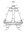
- FIG. 2 and 3 shown views of the first support plate 14 and connected to the first support plate 14 bushings 7, 8, 9 show the alignment of the major axes of the bushings, 7, 8, 9 and the arrangements of the first ends 71, 81, 91 and the second ends 72, 82, 92 on the circular paths.
- the main axes of the bushings 7, 8, 9 lie in such a way to one another that all major axes intersect approximately in one point.
- FIGS. 4 and 5 show two views of a second support plate 20 on which a fourth passage 21, a fifth passage 22 and a sixth passage 23 are mounted. Except for the orientation of the main axes of the second support plate 20 associated bushings 21, 22, 23, the structural design corresponds in principle to the first variant described above.
- the first ends 211, 221, 231 of the second support plate 20 associated bushings 21, 22, 23 are as well as their second ends 212, 222, 232 arranged in their projection on a straight line.
- the major axes of the fourth implementation 21 and the sixth Feedthrough 23 are inclined to the main axis of the fifth feedthrough 22. This inclination is effected by arranged on the second support plate 20 flange 24a, 24b, 24c.
- the flange surfaces 24a, 24b, 24c of the second support plate 20 are arranged on the first ends 211, 221, 231 of the passages 21, 22, 23 facing the top surface of the second support plate 20.
- first variant of a high-voltage feedthrough assembly 1 and in the FIGS. 4 and 5 shown second variant of a support plate 20 are also combinations of these two variants with respect to the position of the main axes of the bushings constructed.
- first ends are arranged on a circular path and second ends are arranged on a straight line or vice versa.
- the support plate is designed in several parts.
Claims (4)
- Dispositif (1) de traversée de haute tension ayant plusieurs, notamment trois traversées (7, 8, 9), qui ont des axes principaux sur lesquels se trouvent, à l'intérieur d'une enveloppe (6), des premières extrémités (71, 81, 91) des traversées (7, 8, 9) et sur lesquels sont disposées des deuxième extrémités (72, 82, 92) des traversées (7, 8, 9), qui se trouvent à l'extérieur de l'enveloppe (6), dans lequel la distance entre les premières extrémités (71, 81) d'une première et d'une deuxième traversée (7, 8) est plus petite que la distance entre les deuxièmes extrémités (72, 82) de la première et de la deuxième traversée (7, 8) et les premières extrémités (71, 81, 91) et les deuxièmes extrémités (72, 82, 92) sont disposées respectivement sur une trajectoire circulaire,
caractérisé en ce que les prolongements des axes principaux d'au moins deux traversées (7, 8) se coupent à peu près en un point. - Dispositif (1) de traversée de haute tension suivant la revendication 1, caractérisé en ce que les prolongements des axes principaux de toutes les traversées (7, 8, 9) se coupent à peu près en un point.
- Dispositif (1) de traversée de haute tension suivant la revendication 1 ou 2, caractérisé en ce que les traversées (7, 8, 9, 21, 22, 23) passent dans des ouvertures d'une plaque (14, 20) commune de support.
- Dispositif (1) de traversée de haute tension suivant la revendication 3, caractérisé en ce que la plaque (14, 20) commune de support a, sur l'une de ses surfaces supérieures, plusieurs surfaces (15a, 15b, 15c ; 24a, 24b, 24c) de flasque inclinées les unes par rapport aux autres pour des traversées (7, 8, 9 ; 21, 22, 23).
Applications Claiming Priority (2)
| Application Number | Priority Date | Filing Date | Title |
|---|---|---|---|
| DE10246993 | 2002-10-02 | ||
| DE2002146993 DE10246993B3 (de) | 2002-10-02 | 2002-10-02 | Hochspannungs-Durchführungsanordnung mit mehreren Durchführungen |
Publications (2)
| Publication Number | Publication Date |
|---|---|
| EP1406364A1 EP1406364A1 (fr) | 2004-04-07 |
| EP1406364B1 true EP1406364B1 (fr) | 2009-07-01 |
Family
ID=31984419
Family Applications (1)
| Application Number | Title | Priority Date | Filing Date |
|---|---|---|---|
| EP20030090292 Expired - Lifetime EP1406364B1 (fr) | 2002-10-02 | 2003-09-11 | Dispositif de traversée haute tension avec plusieurs traversées |
Country Status (2)
| Country | Link |
|---|---|
| EP (1) | EP1406364B1 (fr) |
| DE (2) | DE10246993B3 (fr) |
Families Citing this family (1)
| Publication number | Priority date | Publication date | Assignee | Title |
|---|---|---|---|---|
| DE102010027423A1 (de) * | 2010-07-14 | 2012-01-19 | Siemens Aktiengesellschaft | Mehrphasig druckgasisoliertes Kabeleinführungsmodul mit einer Kapselung |
Family Cites Families (9)
| Publication number | Priority date | Publication date | Assignee | Title |
|---|---|---|---|---|
| US1928636A (en) * | 1929-10-14 | 1933-10-03 | Line Material Co | Pot head |
| GB927457A (en) * | 1959-02-13 | 1963-05-29 | Ass Elect Ind | Improvements in and relating to electrical bushings |
| DE3431357A1 (de) * | 1984-08-25 | 1986-03-06 | Brown, Boveri & Cie Ag, 6800 Mannheim | Anschlussvorrichtung an hochspannungsfreileitungen |
| JPH0651392B2 (ja) * | 1986-11-08 | 1994-07-06 | 平岡織染株式会社 | 光輝性シ−ト |
| JP3412982B2 (ja) * | 1994-11-18 | 2003-06-03 | 東芝Itコントロールシステム株式会社 | ガス絶縁変電設備 |
| DE19720089A1 (de) | 1997-05-14 | 1998-11-19 | Abb Patent Gmbh | Dreipoliger Kabelendverschluß |
| DE19720092A1 (de) * | 1997-05-14 | 1998-11-19 | Abb Patent Gmbh | Kabelendverschluß |
| FR2789798B1 (fr) * | 1999-02-15 | 2004-01-09 | Alstom | Module de disjoncteur auto-sectionneur, moyenne tension et poste de distribution d'energie correspondant |
| DE19908304A1 (de) * | 1999-02-26 | 2000-08-31 | Abb Patent Gmbh | Schaltanlagen-Container |
-
2002
- 2002-10-02 DE DE2002146993 patent/DE10246993B3/de not_active Expired - Fee Related
-
2003
- 2003-09-11 DE DE50311654T patent/DE50311654D1/de not_active Expired - Lifetime
- 2003-09-11 EP EP20030090292 patent/EP1406364B1/fr not_active Expired - Lifetime
Also Published As
| Publication number | Publication date |
|---|---|
| DE50311654D1 (de) | 2009-08-13 |
| EP1406364A1 (fr) | 2004-04-07 |
| DE10246993B3 (de) | 2004-05-27 |
Similar Documents
| Publication | Publication Date | Title |
|---|---|---|
| EP0744803B1 (fr) | Sectionneur pour une installation de commutation à haute tension, blindé et à isolation gazeuse | |
| DE3610742A1 (de) | Stuetzisolator | |
| DE2123549C3 (de) | Vorrichtung zum elektrischen Verbinden eines Stromschienensystems mit einem Anlagenbauteil | |
| EP1249910A2 (fr) | Disjoncteur haute-tension pour une installation de commutation à isolation gaseuse | |
| DE3521945A1 (de) | Trennschalter fuer eine metallgekapselte, druckgasisolierte hochspannungsschaltanlage | |
| DE4320906A1 (de) | Druckgasisolierter Hochspannungs-Leistungsschalter | |
| EP1406364B1 (fr) | Dispositif de traversée haute tension avec plusieurs traversées | |
| DE3540547A1 (de) | Hochspannungsstromwandler und verfahren zur herstellung eines derartigen hochspannungsstromwandlers | |
| WO2010133692A1 (fr) | Module isolé par gaz pour installation de commutation | |
| DE3317827C2 (de) | Gasisolierte Hochspannungsdurchführung | |
| WO2007033947A1 (fr) | Ensemble barre collectrice pour une installation de distribution electrique a double face de commande | |
| EP0202192B1 (fr) | Installation haute tension blindée à isolation à gaz sous pression | |
| EP2283492B1 (fr) | Ensemble comprenant une traversée de mesure étanche aux gaz | |
| DE102011088353A1 (de) | Stützisolatoranordnung | |
| DE10128422C1 (de) | Sammelschienenverbinder | |
| EP1691388B1 (fr) | Connecteur enfichable | |
| EP0073423A1 (fr) | Element de liaison d'un conducteur isolé par un corps solide | |
| EP1653581B1 (fr) | Installation de commutation | |
| EP2047484A1 (fr) | Element de raccordement a monter sur un boitier de securite | |
| EP2273525B1 (fr) | Commutateur de puissance électrique | |
| CH677548A5 (en) | HV cable bushing for transformer etc. | |
| DE102004061277A1 (de) | Mehrphasiges Schaltgerät mit zumindest drei gleichartigen Unterbrechereinheiten | |
| EP0285545B1 (fr) | Disjoncteur électrique à haute tension particulièrement disjoncteur à gaz comprimé | |
| DE102009022103A1 (de) | Gasisolierte Hochspannungsschaltanlage | |
| EP1133775A1 (fr) | Traversee haute tension |
Legal Events
| Date | Code | Title | Description |
|---|---|---|---|
| PUAI | Public reference made under article 153(3) epc to a published international application that has entered the european phase |
Free format text: ORIGINAL CODE: 0009012 |
|
| AK | Designated contracting states |
Kind code of ref document: A1 Designated state(s): AT BE BG CH CY CZ DE DK EE ES FI FR GB GR HU IE IT LI LU MC NL PT RO SE SI SK TR |
|
| AX | Request for extension of the european patent |
Extension state: AL LT LV MK |
|
| 17P | Request for examination filed |
Effective date: 20040719 |
|
| AKX | Designation fees paid |
Designated state(s): CH DE FR LI |
|
| 17Q | First examination report despatched |
Effective date: 20080303 |
|
| GRAP | Despatch of communication of intention to grant a patent |
Free format text: ORIGINAL CODE: EPIDOSNIGR1 |
|
| GRAS | Grant fee paid |
Free format text: ORIGINAL CODE: EPIDOSNIGR3 |
|
| GRAA | (expected) grant |
Free format text: ORIGINAL CODE: 0009210 |
|
| AK | Designated contracting states |
Kind code of ref document: B1 Designated state(s): CH DE FR LI |
|
| REG | Reference to a national code |
Ref country code: CH Ref legal event code: EP |
|
| REG | Reference to a national code |
Ref country code: CH Ref legal event code: NV Representative=s name: SIEMENS SCHWEIZ AG |
|
| REF | Corresponds to: |
Ref document number: 50311654 Country of ref document: DE Date of ref document: 20090813 Kind code of ref document: P |
|
| PGFP | Annual fee paid to national office [announced via postgrant information from national office to epo] |
Ref country code: DE Payment date: 20091120 Year of fee payment: 7 Ref country code: CH Payment date: 20091208 Year of fee payment: 7 |
|
| PLBE | No opposition filed within time limit |
Free format text: ORIGINAL CODE: 0009261 |
|
| STAA | Information on the status of an ep patent application or granted ep patent |
Free format text: STATUS: NO OPPOSITION FILED WITHIN TIME LIMIT |
|
| 26N | No opposition filed |
Effective date: 20100406 |
|
| REG | Reference to a national code |
Ref country code: CH Ref legal event code: PL |
|
| REG | Reference to a national code |
Ref country code: FR Ref legal event code: ST Effective date: 20110531 |
|
| REG | Reference to a national code |
Ref country code: DE Ref legal event code: R119 Ref document number: 50311654 Country of ref document: DE Effective date: 20110401 |
|
| PG25 | Lapsed in a contracting state [announced via postgrant information from national office to epo] |
Ref country code: LI Free format text: LAPSE BECAUSE OF NON-PAYMENT OF DUE FEES Effective date: 20100930 Ref country code: FR Free format text: LAPSE BECAUSE OF NON-PAYMENT OF DUE FEES Effective date: 20100930 Ref country code: CH Free format text: LAPSE BECAUSE OF NON-PAYMENT OF DUE FEES Effective date: 20100930 Ref country code: DE Free format text: LAPSE BECAUSE OF NON-PAYMENT OF DUE FEES Effective date: 20110401 |
|
| PGFP | Annual fee paid to national office [announced via postgrant information from national office to epo] |
Ref country code: FR Payment date: 20091008 Year of fee payment: 7 |