EP2146180B1 - Werkzeug zum Messen eines Innendurchmessers - Google Patents
Werkzeug zum Messen eines Innendurchmessers Download PDFInfo
- Publication number
- EP2146180B1 EP2146180B1 EP09165272.7A EP09165272A EP2146180B1 EP 2146180 B1 EP2146180 B1 EP 2146180B1 EP 09165272 A EP09165272 A EP 09165272A EP 2146180 B1 EP2146180 B1 EP 2146180B1
- Authority
- EP
- European Patent Office
- Prior art keywords
- spindle
- contact pieces
- conical member
- displacement
- degrees
- Prior art date
- Legal status (The legal status is an assumption and is not a legal conclusion. Google has not performed a legal analysis and makes no representation as to the accuracy of the status listed.)
- Not-in-force
Links
Images

Classifications
-
- G—PHYSICS
- G01—MEASURING; TESTING
- G01B—MEASURING LENGTH, THICKNESS OR SIMILAR LINEAR DIMENSIONS; MEASURING ANGLES; MEASURING AREAS; MEASURING IRREGULARITIES OF SURFACES OR CONTOURS
- G01B5/00—Measuring arrangements characterised by the use of mechanical techniques
- G01B5/08—Measuring arrangements characterised by the use of mechanical techniques for measuring diameters
- G01B5/12—Measuring arrangements characterised by the use of mechanical techniques for measuring diameters internal diameters
-
- G—PHYSICS
- G01—MEASURING; TESTING
- G01B—MEASURING LENGTH, THICKNESS OR SIMILAR LINEAR DIMENSIONS; MEASURING ANGLES; MEASURING AREAS; MEASURING IRREGULARITIES OF SURFACES OR CONTOURS
- G01B3/00—Measuring instruments characterised by the use of mechanical techniques
- G01B3/002—Details
- G01B3/008—Arrangements for controlling the measuring force
Definitions
- the present invention relates to an inside diameter measuring tool.
- An inside diameter measuring tool called as a Holtest has been known as a device for measuring an inner diameter of an object to be measured.
- the inside diameter measuring tool includes: a body; an axially moving spindle having a screw to be screwed to the body; a plurality of contact pieces provided on the body, the contact pieces advancing and retracting in a direction substantially orthogonal to the axial direction of the spindle; and a conical member interposed between the contact pieces and the spindle, the conical member moving the contact pieces in the direction substantially orthogonal to the axial direction of the spindle in accordance with the axial movement of the spindle (see, for instance, Document 1: JP-U-60-41811 and US-A-4536963 ).
- Typical inside diameter measuring tools are configured so that the lead of the screw provided on the spindle is 0.5 mm and the cone angle ⁇ of the conical member is approximately 53 degrees in order to equalize the displacement of the contact pieces and the displacement of the spindle.
- displacement of one of the contact pieces is represented by (displacement of the spindle) ⁇ (tan( ⁇ ⁇ 1/2). Since tan(53 ⁇ 1/2) is approximately equal to 0.5, the displacement of the contact pieces (total displacement of two contact pieces among the plurality of contact pieces) and the displacement of the spindle can be equalized.
- One solution for the above problem is to enlarge the cone angle of the conical member.
- the cone angle is 90 degrees, the contact pieces can be advanced/retracted by approximately double distance even with the same number of rotation(s) of the spindle as that of the typical tool.
- An object of the present invention is to provide an inside diameter measurement tool capable of enhancing the operability, operation efficiency and measurement accuracy when an object is to be measured while minimizing a frictional force caused between contact pieces and a conical member to enhance durability.
- An inside diameter measurement tool includes: a main body; a spindle provided with a screw that is screwed with the main body, the spindle advancing and retracting in an axial direction thereof; a plurality of contact pieces provided on the main body, the contact pieces advancing and retracting in a direction substantially orthogonal to the axial direction of the spindle; and a conical member interposed between the contact pieces and the spindle, the conical member advancing and retracting the contact pieces in the direction substantially orthogonal to the axial direction of the spindle in accordance with the axial advancement and retraction of the spindle, in which a lead of the screw of the spindle is 1.0 mm or more and a cone angle of the conical member is less than 53 degrees.
- the lead of the screw of the axially advancing/retracting spindle is 1.0 mm or more, the axial feed amount of the spindle per one rotation of the spindle is increased as compared with a conventional arrangement.
- a large number of rotations of the screw are not necessary for measuring an object to be measured, thereby enhancing the work efficiency and operability.
- the cone angle of the conical member is less than 53 degrees, the displacement of the contact pieces in the direction substantially orthogonal to the axial direction of the spindle per predetermined displacement of the spindle becomes small as compared to an arrangement employing a conical member with conical angle of 90 degrees. Further, the distance for which the contact pieces are in contact with the conical surface of the conical member increases to reduce the frictional force generated in the slide movement of the conical member and the contact pieces, thereby enhancing the durability.
- the lead of the screw of the spindle may be 2.0 mm and the cone angle of the conical member may be approximately 28 degrees.
- the contact piece can be displaced for 1.0 mm with a less number of rotation of the spindle than a conventional arrangement, so that work efficiency and operability can be enhanced. Further, the distance for which the contact pieces are in contact with the conical surface of the conical member increases to reduce the frictional force generated in the slide movement of the conical member and the contact pieces, thereby enhancing the durability.
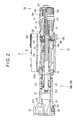
- Fig. 1 is an exploded perspective view of a Holtest 1 (inside diameter measurement tool) according to this exemplary embodiment.
- Fig. 2 is a cross section of the Holtest 1.
- the Holtest 1 includes a main body 10 and a plurality of measuring heads 20A and 20B.
- the measuring heads 20A and 20B are exchangably used in accordance with an inner diameter of an object to be measured.
- the main body 10 includes: a rectangular case 11; a substantially cylindrical sleeves 12A, 12B coaxially attached on both sides of the case 11; a spindle 15 screwed with an inner circumference of the sleeve 12B, the spindle 15 advancing and retracting in an axial direction thereof; a detector 16 for detecting the axial displacement of the spindle 15; a thimble 17 for advancing and retracting the spindle 15; and a constant pressure mechanism 18 provided adjacent to a base end of the spindle 15, the constant pressure mechanism 18 allowing a free rotation of the thimble 17 against the spindle 15 when more than a predetermined load is applied on the spindle 15.
- the case 11 is provided with a display unit 111 that digitally displays the axial displacement of the spindle 15 detected by the detector 16.
- the sleeve 12A is provided with a male screw 121 with which one of the measuring heads 20A and 20B is screwed.
- An outer sleeve 19 is attached to an outer circumference of the sleeve 12B.
- a female screw 13 is provided on the inner circumference of the sleeve 12B. Graduations (not shown) are axially provided on the outer circumference of the outer sleeve 19.
- a male screw 14 to be screwed with the female screw 13 of the sleeve 12B is provided on the spindle 15 adjacent to the base end thereof.
- a tapered section 151 is provided on the spindle 15 further adjacent to the base end.
- the lead of the male screw 14 is 2.0 mm.
- An engaging groove 153 is axially provided approximately at an axial center of the spindle 15.
- the thimble 17 is fitted onto the tapered section 151 from the base end of the spindle 15 so that the thimble 17 covers the outer sleeve 19.
- Graduations (not shown) that represent the displacement of the spindle 15 in conjunction with the graduations of the outer sleeve 19 are circumferentially provided on the outer circumference of the thimble 17.
- a screw hole 152 is provided inside the tapered section 151.
- the detector 16 includes a so-called rotary encoder having a stator 162, a stator bushing 163, a rotor bushing 164 and a rotor 165, and a processor (not shown) for calculating the displacement of the spindle 15 based on an output signal of the rotary encoder and converting the displacement into the displacement of the below-described contact pieces.
- the stator 162 is penetrated by the spindle 15 via the stator bushing 163 to be fitted and rigidly secured on an end of the sleeve 12B.
- the rotor bushing 164 is penetrated by the spindle 15 and is provided with an engaging pin 161 to be engaged with the engaging groove of the spindle 15, so that the rotor bushing 164 is rotated integrally with the spindle 15.
- the rotor 165 is penetrated by the spindle 15 and is engaged with the rotor bushing 164 to be rotated integrally with the rotor bushing 164.
- the rotor 165 outputs a relative angle signal indicating an angle of the rotor 165 relative to the stator 162.
- the processor calculates the rotation of the spindle 15 based on the relative angle signal outputted by the rotor 165 to calculate the displacement of the spindle based on the rotation of the spindle 15 and the lead of the male screw 13.
- the displacement of the spindle 15 calculated by the processor is digitally displayed on the display unit 111 after being converted into the displacement of the contact pieces, as described above.
- the constant pressure mechanism 18 transmits the rotation of the thimble 17 to the spindle 15 while allowing a free rotation of the thimble 17 against the spindle 15 when more than a predetermined load is applied on the spindle 15 to provide a constant measurement pressure.
- the constant pressure mechanism 18 includes: a shaft 181 screwed with the screw hole 152; a ratchet sleeve 182 rotatably supported on an outer circumference of the thimble 17; and a coil spring 184 that biases the ratchet sleeve 182 toward the shaft 181.
- the ratchet sleeve 182 When the ratchet sleeve 182 is rotated, since the ratchet sleeve 182 is biased toward the shaft 181 by virtue of the coil spring 184, the thimble 17 is also rotated. On the other hand, when more than a predetermined load is applied on the spindle 15, the ratchet sleeve 182 is freely rotated against the shaft 181, so that the measurement can be conducted under a constant pressure.
- Each of the measuring heads 20A and 20B includes: a bottomed cylindrical head body 21; a plurality of contact pieces 22 attached to an end of the head body 21; and a conical member 23 disposed inside the head body 21.
- the head body 21 is provided with: a female screw 211 to be screwed with the male screw 121 of the sleeve 12A; a housing bore 212 that allows advancement and retraction of the conical member 23 along an axial direction of the head body 21; and openings 213 for advancing and retracting the contact pieces 22 in a direction substantially orthogonal to the axial direction of the spindle 15.
- the openings 213 are provided on the distal end of the head body 21 at every 120 degrees interval.
- the contact pieces 22 are slidably disposed in the openings 213 to be advanced and retracted in the direction substantially orthogonal to the axial direction of the spindle 15. Further, the contact piece 22 is biased toward the conical member 23 by the coil spring 24.
- the conical member 23 is accommodated within the housing bore 212 of the head body 21 in a manner capable of axial advancement and retraction and is in contact with the distal end of the spindle 15.
- a chamfered portion 221 provided on each of the contact pieces 22 is brought into contact with the conical surface 231 of the conical member 23.
- the cone angle of the conical member 23 is approximately 28 degrees.
- the ratchet sleeve 182 When an operator rotates the ratchet sleeve 182 in a feed direction (in a direction indicated by an arrow in Fig. 1 ), the ratchet sleeve 182 is biased by the coil spring 184 toward the shaft 181 to be rotated together with the thimble 17 and, consequently with the spindle 15.
- the spindle 15 When the male screw 14 of the spindle 15 is screwed with the female screw 13 of the sleeve 12B, the spindle 15 is moved toward the conical member 23 along the axial direction thereof. Then, the spindle 15 presses the conical member 23.
- the contact pieces 22 are in contact with the conical surface 231 of the conical member 23, the contact pieces 22 are moved in a direction substantially orthogonal to the axial direction against the biasing force of the coil spring 184 to be abutted to an inner circumference of an object to be measured.
- the ratchet sleeve 182 is further rotated in the feed direction after the contact piece 22 is abutted to the inner circumference of the object, since the spindle 15 cannot be further advanced, more than a predetermined load is applied on the spindle to freely rotate the ratchet sleeve 182 against the shaft 181. Accordingly, the object can be measured with the constant pieces 22 at a constant measurement pressure, thereby avoiding variation in the measurement value among operators.
- the ratchet sleeve 182 may be rotated for attaining the constant measurement pressure after rotating the thimble 17.
- the spindle 15 with 2.0 mm lead is axially displaced for 2.0 mm. Since the cone angle of the conical member 23 is approximately 28 degrees, the contact piece 22 is displaced in radial direction of the conical member 23 for 0.5 mm (total 1.0 mm for a pair of contact pieces 22). In a conventional tool having 0.5 mm lead and 53 degrees cone angle, two rotations are required for displacing the contact piece 22 for 1.0 mm in a radial direction of the cone member 23. However, only one rotation of the spindle 15 is required for 1.0 mm displacement of the contact piece 22 in the radial direction of the conical member 23 in the above exemplary embodiment, so that the operability and work efficiency can be enhanced.
- the lead of the spindle 15 is 2.0 mm (four times larger than a conventional tool).
- the displacement transmitted to the contact pieces 22 becomes four times greater than that of the tool with 0.5 mm lead causing 2.0 mm displacement of the contact pieces 22 in the radial direction of the conical member 23. Accordingly, a measurement error can occur in the conventional arrangement with 53 degrees cone angle.
- the cone angle is approximately 28 degrees in the above exemplary embodiment, the displacement transmitted to the contact pieces 22 can be restrained to a degree two times larger than the displacement of the spindle, so that the measurement accuracy can be enhanced.
- the cone angle is approximately 28 degrees
- the slide displacement of the contact pieces 22 on the conical surface 231 of the conical member 23 becomes larger than the conventional arrangement, whereby the frictional force can be reduced. Accordingly, the abrasion on the conical member 23 and the contact piece 22 can be restrained, thereby enhancing the durability.
- the lead of the male screw 14 is 2.0 mm and the cone angle of the conical member 23 is approximately 28 degrees.
- the lead and the conical member can be set as desired in accordance with the specific application, structure of the inside diameter measurement tool and the demand for quick feed as long as excessive increase in the friction against the slide surface on the conical member and the displacement of the spindle 15 can be accurately and easily converted into the displacement of the contact pieces 22.
- the detector 16 includes an electrostatic encoder, any encoder such as optical encoder and electromagnetic encoder may be provided on the detector 16 as long as the rotation of the spindle 15 can be detected.
- Holtest 1 is a digital Holtest in the above exemplary embodiment, analog Holtest may alternatively be used.
- the male screw 14 of the above exemplary embodiment is provided by a single thread, a multiple thread may alternatively be used.
Claims (2)
- Werkzeug zum Messen eines Innendurchmessers, umfassend:einen Hauptkörper (10);eine Spindel (15) mit einer Schraube (14), die mit dem Hauptkörper (10) verschraubt wird, wobei sich die Spindel sich in axialer Richtung davon vor- und zurückbewegt;mehrere Kontaktstücke (22) am Hauptkörper (10), wobei die Kontaktstücke sich in einer im Wesentlichen orthogonalen Richtung zur axialen Richtung der Spindel (15) vor- und zurückbewegen; undein konisches Element (23), das zwischen den Kontaktstücken (22) und der Spindel (15) platziert ist, wobei das konische Element die Kontaktstücke (22) in der im Wesentlichen orthogonal zur axialen Richtung der Spindel (15) verlaufenden Richtung gemäß der axialen Vor- und Rückbewegung der Spindel (15) vor- und zurückbewegt, dadurch gekennzeichnet, dasseine Steigung bzw. Ganghöhe der Schraube (14) der Spindel (15) 1,0 mm oder mehr beträgt und ein Konuswinkel des konischen Elements (23) weniger als 53 Grad beträgt.
- Werkzeug zum Messen eines Innendurchmessers gemäß Anspruch 1, wobei die Steigung bzw. Ganghöhe der Schraube (14) der Spindel (15) 2,0 mm beträgt und der Konuswinkel des konischen Elements (23) zirka 28 Grad beträgt.
Applications Claiming Priority (1)
| Application Number | Priority Date | Filing Date | Title |
|---|---|---|---|
| JP2008182569A JP2010019783A (ja) | 2008-07-14 | 2008-07-14 | 内径測定器 |
Publications (2)
| Publication Number | Publication Date |
|---|---|
| EP2146180A1 EP2146180A1 (de) | 2010-01-20 |
| EP2146180B1 true EP2146180B1 (de) | 2015-01-28 |
Family
ID=41066474
Family Applications (1)
| Application Number | Title | Priority Date | Filing Date |
|---|---|---|---|
| EP09165272.7A Not-in-force EP2146180B1 (de) | 2008-07-14 | 2009-07-13 | Werkzeug zum Messen eines Innendurchmessers |
Country Status (4)
| Country | Link |
|---|---|
| US (1) | US8033032B2 (de) |
| EP (1) | EP2146180B1 (de) |
| JP (1) | JP2010019783A (de) |
| CN (1) | CN101629819B (de) |
Families Citing this family (21)
| Publication number | Priority date | Publication date | Assignee | Title |
|---|---|---|---|---|
| US7950158B2 (en) * | 2009-02-03 | 2011-05-31 | Keystone Ventures Limited | Method and apparatus for measuring the interior dimensions of a glove |
| IT1393306B1 (it) * | 2009-03-27 | 2012-04-20 | Marposs Spa | Apparecchio di misura e controllo |
| US8365428B2 (en) * | 2010-12-15 | 2013-02-05 | Lockheed Martin Corporation | Hole grip length measurement apparatus |
| JP5323902B2 (ja) * | 2011-08-29 | 2013-10-23 | 株式会社日進製作所 | エアマイクロメータの測定ヘッド及びその製造方法 |
| CN102519414B (zh) * | 2011-12-30 | 2014-02-12 | 成都发动机(集团)有限公司 | 高压压气机整流器内径测量装置 |
| WO2013118912A1 (ja) | 2012-02-09 | 2013-08-15 | 株式会社Ihi | 内径測定装置 |
| JP5915222B2 (ja) | 2012-02-09 | 2016-05-11 | 株式会社Ihi | 内径測定装置 |
| JP5915223B2 (ja) | 2012-02-09 | 2016-05-11 | 株式会社Ihi | 内径測定装置及び内径測定方法 |
| JP2013164274A (ja) | 2012-02-09 | 2013-08-22 | Ihi Corp | 内径測定装置 |
| JP5880096B2 (ja) | 2012-02-09 | 2016-03-08 | 株式会社Ihi | 内径測定装置 |
| JP5880097B2 (ja) * | 2012-02-09 | 2016-03-08 | 株式会社Ihi | 内径測定装置 |
| US9372061B2 (en) * | 2012-02-09 | 2016-06-21 | Ihi Corporation | Inner diameter measuring device |
| CN102944397B (zh) * | 2012-11-02 | 2015-04-22 | 浙江环球滤清器有限公司 | 滤清器的出油口螺纹检测方法及其检测装置 |
| US9297628B2 (en) * | 2013-10-21 | 2016-03-29 | John Lang Sluder, III | Ammunition primer pocket gauge tool |
| CN103612230A (zh) * | 2013-12-11 | 2014-03-05 | 中国航空工业标准件制造有限责任公司 | 精确测量孔径的辅助夹具 |
| CN103837118B (zh) * | 2014-03-21 | 2017-01-11 | 西南石油大学 | 一种管道螺旋测量装置 |
| USD774928S1 (en) * | 2015-03-11 | 2016-12-27 | Mitutoyo Corporation | Caliper |
| JP6768988B1 (ja) * | 2019-03-15 | 2020-10-14 | ビブリロォス株式会社 | マイクロヘッド及びこれを用いたステージ機構 |
| JP2023142301A (ja) | 2022-03-24 | 2023-10-05 | 株式会社ミツトヨ | 内径測定ユニット、フローティング継手機構部、および、測定ユニット |
| JP2023142304A (ja) | 2022-03-24 | 2023-10-05 | 株式会社ミツトヨ | 自動内径測定装置の制御方法、および、自動測定装置の制御方法 |
| JP2023142302A (ja) | 2022-03-24 | 2023-10-05 | 株式会社ミツトヨ | 内径測定ユニット、フローティング継手機構部、および、測定ユニット |
Family Cites Families (20)
| Publication number | Priority date | Publication date | Assignee | Title |
|---|---|---|---|---|
| DE216974C (de) | ||||
| DE368494C (de) | 1923-02-06 | Fortuna Werke Maschf Ag | Innenmessgeraet mit Messtaster | |
| US1439989A (en) * | 1920-08-04 | 1922-12-26 | Johansson Ab C E | Gauge for measuring internal dimensions |
| US1656180A (en) * | 1927-01-26 | 1928-01-17 | Gustav A Eisele | Micrometer expansion gauge |
| US2454246A (en) * | 1944-10-17 | 1948-11-16 | Fed Products Corp | Bore gauge |
| US2456497A (en) * | 1947-03-01 | 1948-12-14 | Stiger Prec Products Inc | Micrometer bore gauge |
| US2788582A (en) * | 1953-03-31 | 1957-04-16 | Middeler Paul | Apparatus for measuring and gauging cylindrical and conical bores and internal screwthreads |
| US2881529A (en) * | 1954-09-17 | 1959-04-14 | Roch Pierre Sarl | Internal diameter micrometer |
| US2822622A (en) * | 1955-02-21 | 1958-02-11 | Meyer Hans | Internal measuring instruments |
| CH449277A (de) * | 1966-12-21 | 1967-12-31 | Meyer Hans | Innenmessgerät |
| US3737808A (en) | 1971-12-29 | 1973-06-05 | Honeywell Inf Systems | Pulse shaping network |
| JPS6041811A (ja) | 1983-08-17 | 1985-03-05 | Mitsubishi Electric Corp | アクテイブ・フイルタ回路 |
| US4536963A (en) | 1983-08-29 | 1985-08-27 | Mitutoyo Mfg. Co., Ltd. | Digital indication type measuring machine |
| JPS6041811U (ja) * | 1983-08-29 | 1985-03-25 | 株式会社ミツトヨ | 内径測定ユニット |
| US4873768A (en) | 1987-04-17 | 1989-10-17 | Gte Valeron Corporation | Dimensioning head for plug gage |
| JPH0712890Y2 (ja) * | 1988-02-26 | 1995-03-29 | 株式会社ミツトヨ | 溝幅測定装置 |
| JPH0418308U (de) * | 1990-06-05 | 1992-02-17 | ||
| US5377421A (en) * | 1993-04-30 | 1995-01-03 | Isler; David | Centering tool for cylinder gauge |
| JP3199684B2 (ja) * | 1998-07-17 | 2001-08-20 | 政人 石井 | 測定装置 |
| WO2004109223A1 (ja) * | 2003-06-09 | 2004-12-16 | Mitutoyo Corporation | 測定器 |
-
2008
- 2008-07-14 JP JP2008182569A patent/JP2010019783A/ja active Pending
-
2009
- 2009-07-13 US US12/501,806 patent/US8033032B2/en not_active Expired - Fee Related
- 2009-07-13 EP EP09165272.7A patent/EP2146180B1/de not_active Not-in-force
- 2009-07-14 CN CN2009101585558A patent/CN101629819B/zh not_active Expired - Fee Related
Also Published As
| Publication number | Publication date |
|---|---|
| EP2146180A1 (de) | 2010-01-20 |
| US8033032B2 (en) | 2011-10-11 |
| CN101629819A (zh) | 2010-01-20 |
| CN101629819B (zh) | 2013-01-23 |
| US20100005676A1 (en) | 2010-01-14 |
| JP2010019783A (ja) | 2010-01-28 |
Similar Documents
| Publication | Publication Date | Title |
|---|---|---|
| EP2146180B1 (de) | Werkzeug zum Messen eines Innendurchmessers | |
| EP1515112B1 (de) | Messgerät | |
| EP1873476B1 (de) | Digitales Wegmessinstrument | |
| EP2149772B1 (de) | Digitales Weglängenmessinstrument | |
| EP2378237B1 (de) | Mikrometer | |
| JP2010525350A (ja) | 回転直線運動を検出するための測定システムおよび回転直線駆動装置 | |
| EP2378238B1 (de) | Wegmessgerät | |
| US6487897B1 (en) | Detector for surface texture measuring instrument | |
| EP1950524B1 (de) | Mikrometer mit Digitalanzeige | |
| EP2131140B1 (de) | Mikrometer | |
| US9551559B2 (en) | Compact 3D contact measuring device | |
| JP7286512B2 (ja) | テストインジケータ | |
| US9982985B2 (en) | Digital comparator having a retractable anvil supported at one end of a U-shaped frame | |
| CN208936925U (zh) | 锥面距离专用检具 | |
| CN109297388B (zh) | 锥面距离专用检具 | |
| CN212254048U (zh) | 一种用于压缩型位移传感器的标定装置 | |
| JP2007285814A (ja) | デジタル式変位測定器 | |
| Grosenbach | Measurement with Micrometers | |
| JP3128248U (ja) | 芯出し器具 | |
| JPS58111711A (ja) | 変位測定装置 |
Legal Events
| Date | Code | Title | Description |
|---|---|---|---|
| PUAI | Public reference made under article 153(3) epc to a published international application that has entered the european phase |
Free format text: ORIGINAL CODE: 0009012 |
|
| AK | Designated contracting states |
Kind code of ref document: A1 Designated state(s): AT BE BG CH CY CZ DE DK EE ES FI FR GB GR HR HU IE IS IT LI LT LU LV MC MK MT NL NO PL PT RO SE SI SK SM TR |
|
| AX | Request for extension of the european patent |
Extension state: AL BA RS |
|
| 17P | Request for examination filed |
Effective date: 20100712 |
|
| 17Q | First examination report despatched |
Effective date: 20100806 |
|
| GRAP | Despatch of communication of intention to grant a patent |
Free format text: ORIGINAL CODE: EPIDOSNIGR1 |
|
| INTG | Intention to grant announced |
Effective date: 20141008 |
|
| RIN1 | Information on inventor provided before grant (corrected) |
Inventor name: HAYASHIDA, SHUJI Inventor name: TACHIKAKE, MASAHIKO Inventor name: FUJIKAWA, YUJI Inventor name: MATSUMOTO, KOUJI |
|
| GRAS | Grant fee paid |
Free format text: ORIGINAL CODE: EPIDOSNIGR3 |
|
| GRAA | (expected) grant |
Free format text: ORIGINAL CODE: 0009210 |
|
| AK | Designated contracting states |
Kind code of ref document: B1 Designated state(s): AT BE BG CH CY CZ DE DK EE ES FI FR GB GR HR HU IE IS IT LI LT LU LV MC MK MT NL NO PL PT RO SE SI SK SM TR |
|
| REG | Reference to a national code |
Ref country code: GB Ref legal event code: FG4D |
|
| REG | Reference to a national code |
Ref country code: CH Ref legal event code: EP |
|
| REG | Reference to a national code |
Ref country code: IE Ref legal event code: FG4D |
|
| REG | Reference to a national code |
Ref country code: DE Ref legal event code: R096 Ref document number: 602009029202 Country of ref document: DE Effective date: 20150312 |
|
| REG | Reference to a national code |
Ref country code: AT Ref legal event code: REF Ref document number: 708414 Country of ref document: AT Kind code of ref document: T Effective date: 20150315 |
|
| REG | Reference to a national code |
Ref country code: AT Ref legal event code: MK05 Ref document number: 708414 Country of ref document: AT Kind code of ref document: T Effective date: 20150128 |
|
| REG | Reference to a national code |
Ref country code: NL Ref legal event code: VDEP Effective date: 20150128 |
|
| REG | Reference to a national code |
Ref country code: LT Ref legal event code: MG4D |
|
| REG | Reference to a national code |
Ref country code: FR Ref legal event code: PLFP Year of fee payment: 7 |
|
| PG25 | Lapsed in a contracting state [announced via postgrant information from national office to epo] |
Ref country code: ES Free format text: LAPSE BECAUSE OF FAILURE TO SUBMIT A TRANSLATION OF THE DESCRIPTION OR TO PAY THE FEE WITHIN THE PRESCRIBED TIME-LIMIT Effective date: 20150128 Ref country code: BG Free format text: LAPSE BECAUSE OF FAILURE TO SUBMIT A TRANSLATION OF THE DESCRIPTION OR TO PAY THE FEE WITHIN THE PRESCRIBED TIME-LIMIT Effective date: 20150428 Ref country code: SE Free format text: LAPSE BECAUSE OF FAILURE TO SUBMIT A TRANSLATION OF THE DESCRIPTION OR TO PAY THE FEE WITHIN THE PRESCRIBED TIME-LIMIT Effective date: 20150128 Ref country code: LT Free format text: LAPSE BECAUSE OF FAILURE TO SUBMIT A TRANSLATION OF THE DESCRIPTION OR TO PAY THE FEE WITHIN THE PRESCRIBED TIME-LIMIT Effective date: 20150128 Ref country code: HR Free format text: LAPSE BECAUSE OF FAILURE TO SUBMIT A TRANSLATION OF THE DESCRIPTION OR TO PAY THE FEE WITHIN THE PRESCRIBED TIME-LIMIT Effective date: 20150128 Ref country code: FI Free format text: LAPSE BECAUSE OF FAILURE TO SUBMIT A TRANSLATION OF THE DESCRIPTION OR TO PAY THE FEE WITHIN THE PRESCRIBED TIME-LIMIT Effective date: 20150128 Ref country code: NO Free format text: LAPSE BECAUSE OF FAILURE TO SUBMIT A TRANSLATION OF THE DESCRIPTION OR TO PAY THE FEE WITHIN THE PRESCRIBED TIME-LIMIT Effective date: 20150428 |
|
| PG25 | Lapsed in a contracting state [announced via postgrant information from national office to epo] |
Ref country code: AT Free format text: LAPSE BECAUSE OF FAILURE TO SUBMIT A TRANSLATION OF THE DESCRIPTION OR TO PAY THE FEE WITHIN THE PRESCRIBED TIME-LIMIT Effective date: 20150128 Ref country code: GR Free format text: LAPSE BECAUSE OF FAILURE TO SUBMIT A TRANSLATION OF THE DESCRIPTION OR TO PAY THE FEE WITHIN THE PRESCRIBED TIME-LIMIT Effective date: 20150429 Ref country code: IS Free format text: LAPSE BECAUSE OF FAILURE TO SUBMIT A TRANSLATION OF THE DESCRIPTION OR TO PAY THE FEE WITHIN THE PRESCRIBED TIME-LIMIT Effective date: 20150528 Ref country code: PL Free format text: LAPSE BECAUSE OF FAILURE TO SUBMIT A TRANSLATION OF THE DESCRIPTION OR TO PAY THE FEE WITHIN THE PRESCRIBED TIME-LIMIT Effective date: 20150128 Ref country code: NL Free format text: LAPSE BECAUSE OF FAILURE TO SUBMIT A TRANSLATION OF THE DESCRIPTION OR TO PAY THE FEE WITHIN THE PRESCRIBED TIME-LIMIT Effective date: 20150128 Ref country code: LV Free format text: LAPSE BECAUSE OF FAILURE TO SUBMIT A TRANSLATION OF THE DESCRIPTION OR TO PAY THE FEE WITHIN THE PRESCRIBED TIME-LIMIT Effective date: 20150128 |
|
| REG | Reference to a national code |
Ref country code: DE Ref legal event code: R097 Ref document number: 602009029202 Country of ref document: DE |
|
| PG25 | Lapsed in a contracting state [announced via postgrant information from national office to epo] |
Ref country code: SK Free format text: LAPSE BECAUSE OF FAILURE TO SUBMIT A TRANSLATION OF THE DESCRIPTION OR TO PAY THE FEE WITHIN THE PRESCRIBED TIME-LIMIT Effective date: 20150128 Ref country code: EE Free format text: LAPSE BECAUSE OF FAILURE TO SUBMIT A TRANSLATION OF THE DESCRIPTION OR TO PAY THE FEE WITHIN THE PRESCRIBED TIME-LIMIT Effective date: 20150128 Ref country code: RO Free format text: LAPSE BECAUSE OF FAILURE TO SUBMIT A TRANSLATION OF THE DESCRIPTION OR TO PAY THE FEE WITHIN THE PRESCRIBED TIME-LIMIT Effective date: 20150128 Ref country code: DK Free format text: LAPSE BECAUSE OF FAILURE TO SUBMIT A TRANSLATION OF THE DESCRIPTION OR TO PAY THE FEE WITHIN THE PRESCRIBED TIME-LIMIT Effective date: 20150128 Ref country code: CZ Free format text: LAPSE BECAUSE OF FAILURE TO SUBMIT A TRANSLATION OF THE DESCRIPTION OR TO PAY THE FEE WITHIN THE PRESCRIBED TIME-LIMIT Effective date: 20150128 |
|
| PLBE | No opposition filed within time limit |
Free format text: ORIGINAL CODE: 0009261 |
|
| STAA | Information on the status of an ep patent application or granted ep patent |
Free format text: STATUS: NO OPPOSITION FILED WITHIN TIME LIMIT |
|
| PG25 | Lapsed in a contracting state [announced via postgrant information from national office to epo] |
Ref country code: IT Free format text: LAPSE BECAUSE OF FAILURE TO SUBMIT A TRANSLATION OF THE DESCRIPTION OR TO PAY THE FEE WITHIN THE PRESCRIBED TIME-LIMIT Effective date: 20150128 |
|
| 26N | No opposition filed |
Effective date: 20151029 |
|
| PG25 | Lapsed in a contracting state [announced via postgrant information from national office to epo] |
Ref country code: MC Free format text: LAPSE BECAUSE OF FAILURE TO SUBMIT A TRANSLATION OF THE DESCRIPTION OR TO PAY THE FEE WITHIN THE PRESCRIBED TIME-LIMIT Effective date: 20150128 Ref country code: SI Free format text: LAPSE BECAUSE OF FAILURE TO SUBMIT A TRANSLATION OF THE DESCRIPTION OR TO PAY THE FEE WITHIN THE PRESCRIBED TIME-LIMIT Effective date: 20150128 |
|
| REG | Reference to a national code |
Ref country code: CH Ref legal event code: PL |
|
| PG25 | Lapsed in a contracting state [announced via postgrant information from national office to epo] |
Ref country code: LU Free format text: LAPSE BECAUSE OF FAILURE TO SUBMIT A TRANSLATION OF THE DESCRIPTION OR TO PAY THE FEE WITHIN THE PRESCRIBED TIME-LIMIT Effective date: 20150713 |
|
| REG | Reference to a national code |
Ref country code: IE Ref legal event code: MM4A |
|
| PG25 | Lapsed in a contracting state [announced via postgrant information from national office to epo] |
Ref country code: LI Free format text: LAPSE BECAUSE OF NON-PAYMENT OF DUE FEES Effective date: 20150731 Ref country code: CH Free format text: LAPSE BECAUSE OF NON-PAYMENT OF DUE FEES Effective date: 20150731 |
|
| PG25 | Lapsed in a contracting state [announced via postgrant information from national office to epo] |
Ref country code: BE Free format text: LAPSE BECAUSE OF FAILURE TO SUBMIT A TRANSLATION OF THE DESCRIPTION OR TO PAY THE FEE WITHIN THE PRESCRIBED TIME-LIMIT Effective date: 20150128 |
|
| REG | Reference to a national code |
Ref country code: FR Ref legal event code: PLFP Year of fee payment: 8 |
|
| PG25 | Lapsed in a contracting state [announced via postgrant information from national office to epo] |
Ref country code: IE Free format text: LAPSE BECAUSE OF NON-PAYMENT OF DUE FEES Effective date: 20150713 |
|
| PG25 | Lapsed in a contracting state [announced via postgrant information from national office to epo] |
Ref country code: MT Free format text: LAPSE BECAUSE OF FAILURE TO SUBMIT A TRANSLATION OF THE DESCRIPTION OR TO PAY THE FEE WITHIN THE PRESCRIBED TIME-LIMIT Effective date: 20150128 |
|
| PG25 | Lapsed in a contracting state [announced via postgrant information from national office to epo] |
Ref country code: HU Free format text: LAPSE BECAUSE OF FAILURE TO SUBMIT A TRANSLATION OF THE DESCRIPTION OR TO PAY THE FEE WITHIN THE PRESCRIBED TIME-LIMIT; INVALID AB INITIO Effective date: 20090713 Ref country code: SM Free format text: LAPSE BECAUSE OF FAILURE TO SUBMIT A TRANSLATION OF THE DESCRIPTION OR TO PAY THE FEE WITHIN THE PRESCRIBED TIME-LIMIT Effective date: 20150128 |
|
| PG25 | Lapsed in a contracting state [announced via postgrant information from national office to epo] |
Ref country code: CY Free format text: LAPSE BECAUSE OF FAILURE TO SUBMIT A TRANSLATION OF THE DESCRIPTION OR TO PAY THE FEE WITHIN THE PRESCRIBED TIME-LIMIT Effective date: 20150128 |
|
| REG | Reference to a national code |
Ref country code: FR Ref legal event code: PLFP Year of fee payment: 9 |
|
| PG25 | Lapsed in a contracting state [announced via postgrant information from national office to epo] |
Ref country code: TR Free format text: LAPSE BECAUSE OF FAILURE TO SUBMIT A TRANSLATION OF THE DESCRIPTION OR TO PAY THE FEE WITHIN THE PRESCRIBED TIME-LIMIT Effective date: 20150128 |
|
| PG25 | Lapsed in a contracting state [announced via postgrant information from national office to epo] |
Ref country code: PT Free format text: LAPSE BECAUSE OF FAILURE TO SUBMIT A TRANSLATION OF THE DESCRIPTION OR TO PAY THE FEE WITHIN THE PRESCRIBED TIME-LIMIT Effective date: 20150128 Ref country code: MK Free format text: LAPSE BECAUSE OF FAILURE TO SUBMIT A TRANSLATION OF THE DESCRIPTION OR TO PAY THE FEE WITHIN THE PRESCRIBED TIME-LIMIT Effective date: 20150128 |
|
| REG | Reference to a national code |
Ref country code: FR Ref legal event code: PLFP Year of fee payment: 10 |
|
| PGFP | Annual fee paid to national office [announced via postgrant information from national office to epo] |
Ref country code: GB Payment date: 20200727 Year of fee payment: 12 Ref country code: FR Payment date: 20200723 Year of fee payment: 12 Ref country code: DE Payment date: 20200721 Year of fee payment: 12 |
|
| REG | Reference to a national code |
Ref country code: DE Ref legal event code: R119 Ref document number: 602009029202 Country of ref document: DE |
|
| GBPC | Gb: european patent ceased through non-payment of renewal fee |
Effective date: 20210713 |
|
| PG25 | Lapsed in a contracting state [announced via postgrant information from national office to epo] |
Ref country code: GB Free format text: LAPSE BECAUSE OF NON-PAYMENT OF DUE FEES Effective date: 20210713 Ref country code: DE Free format text: LAPSE BECAUSE OF NON-PAYMENT OF DUE FEES Effective date: 20220201 |
|
| PG25 | Lapsed in a contracting state [announced via postgrant information from national office to epo] |
Ref country code: FR Free format text: LAPSE BECAUSE OF NON-PAYMENT OF DUE FEES Effective date: 20210731 |