EP2145703A1 - Rolling load prediction learning method for hot plate rolling - Google Patents
Rolling load prediction learning method for hot plate rolling Download PDFInfo
- Publication number
- EP2145703A1 EP2145703A1 EP09720988A EP09720988A EP2145703A1 EP 2145703 A1 EP2145703 A1 EP 2145703A1 EP 09720988 A EP09720988 A EP 09720988A EP 09720988 A EP09720988 A EP 09720988A EP 2145703 A1 EP2145703 A1 EP 2145703A1
- Authority
- EP
- European Patent Office
- Prior art keywords
- rolling
- prediction
- pass
- rolling load
- thickness
- Prior art date
- Legal status (The legal status is an assumption and is not a legal conclusion. Google has not performed a legal analysis and makes no representation as to the accuracy of the status listed.)
- Granted
Links
Images


Classifications
-
- B—PERFORMING OPERATIONS; TRANSPORTING
- B21—MECHANICAL METAL-WORKING WITHOUT ESSENTIALLY REMOVING MATERIAL; PUNCHING METAL
- B21B—ROLLING OF METAL
- B21B37/00—Control devices or methods specially adapted for metal-rolling mills or the work produced thereby
- B21B37/58—Roll-force control; Roll-gap control
-
- B—PERFORMING OPERATIONS; TRANSPORTING
- B21—MECHANICAL METAL-WORKING WITHOUT ESSENTIALLY REMOVING MATERIAL; PUNCHING METAL
- B21B—ROLLING OF METAL
- B21B37/00—Control devices or methods specially adapted for metal-rolling mills or the work produced thereby
-
- B—PERFORMING OPERATIONS; TRANSPORTING
- B21—MECHANICAL METAL-WORKING WITHOUT ESSENTIALLY REMOVING MATERIAL; PUNCHING METAL
- B21B—ROLLING OF METAL
- B21B2261/00—Product parameters
- B21B2261/02—Transverse dimensions
- B21B2261/04—Thickness, gauge
-
- B—PERFORMING OPERATIONS; TRANSPORTING
- B21—MECHANICAL METAL-WORKING WITHOUT ESSENTIALLY REMOVING MATERIAL; PUNCHING METAL
- B21B—ROLLING OF METAL
- B21B2265/00—Forming parameters
- B21B2265/12—Rolling load or rolling pressure; roll force
-
- B—PERFORMING OPERATIONS; TRANSPORTING
- B21—MECHANICAL METAL-WORKING WITHOUT ESSENTIALLY REMOVING MATERIAL; PUNCHING METAL
- B21B—ROLLING OF METAL
- B21B2275/00—Mill drive parameters
- B21B2275/10—Motor power; motor current
- B21B2275/12—Roll torque
-
- B—PERFORMING OPERATIONS; TRANSPORTING
- B21—MECHANICAL METAL-WORKING WITHOUT ESSENTIALLY REMOVING MATERIAL; PUNCHING METAL
- B21B—ROLLING OF METAL
- B21B37/00—Control devices or methods specially adapted for metal-rolling mills or the work produced thereby
- B21B37/16—Control of thickness, width, diameter or other transverse dimensions
Definitions
- the present invention relates to a learning method of rolling load prediction for hot rolling.
- the ratio c P between the actual value of the rolling force P exp at an actual pass for the stock and the predicted value P cal of the rolling force at a rolling force model for that actual pass is considered as an indicator of the prediction error of the rolling force at an actual pass (hereinafter referred to as the "prediction error rate").
- C P P exp P cal
- the trend in prediction error of the rolling load in actual passes is not always constant for different passes even for the same stock.
- the error indicator C P of rolling load prediction in an actual pass found by formula (1) is multiplied with a gain ⁇ to flatten the trend in prediction error of the rolling load so as to set the learning coefficient C F for rolling force prediction at the predicted pass.
- Japanese Patent Publication (A) No. 50-108150 discloses the art of setting the learning coefficient C F of rolling force prediction at a predicted pass at which time, when the prediction error of the rolling load at the actual pass would be near the average value of past results, increasing the gain ⁇ multiplied with the prediction error of the rolling load at the actual pass and, when not, setting said gain ⁇ small so as to improve the precision of the rolling load prediction.
- the prediction error of the rolling load at an actual pass is distributed over a wide range, so with the method of adjusting the gain ⁇ to be multiplied with the error of the rolling load prediction in an actual pass in accordance with the error from the average value of the past results of the prediction error of the rolling load at an actual pass so as to set the learning coefficient C F of the rolling force prediction at the predicted pass, it is difficult to stably raise the precision of the rolling load prediction.
- Japanese Patent Publication (A) No. 2000-126809 discloses the art of expressing the prediction error of the rolling load by a weighted sum of the prediction error of the friction coefficient and the prediction error of the material deformation resistance and correcting the respective weighting coefficients at each pass so as to thereby improve the prediction precision of the rolling load.
- Japanese Patent Publication (A) No. 1-133606 discloses the art of using weighting coefficients showing the degrees of effect of the different parameters of a rolling load prediction formula on the rolling load so as to determine the learning coefficient for rolling load prediction to thereby improve the precision of the rolling load prediction.
- Japanese Patent Publication (A) No. 10-263640 discloses the art of separating the learning coefficient for rolling load prediction into a component for correction of error distinctive to the rolling material and a component for correction of error due to aging of the rolling mill to thereby improve the precision of the rolling load prediction.
- the error factors of the rolling load include various factors such as the surface conditions of the stock and rolling rolls, the temperature and deformation characteristics of the stock, the precision of setting the rolling conditions, etc. It is extremely difficult to logically extract and estimate error of this large number of influencing factors.
- the present invention was made in consideration of the above problems and has as its object the provision of a learning method of rolling load prediction for hot rolling using the prediction error of the rolling load at an actual pass of a rolling material to correct the predicted value of the rolling load at subsequent rolling passes to thereby stably improve the precision of the rolling load prediction.
- the rolling load indicates the rolling force, the rolling torque, the rolling power, etc.
- the calculated value of the rolling load is the rolling force, obtained by entering the actual values of the rolling conditions in an actual pass into a prediction formula of the rolling force, multiplied with the learning coefficient of the rolling force prediction for that pass.
- the smaller the thickness of the rolling material at the predicted pass concerned the smaller the effect of the prediction error of the rolling load at an actual pass on the prediction error of the rolling load at that predicted pass, so learned that making the gain multiplied with the prediction error of the rolling load at an actual pass smaller, the smaller the thickness of the stock at the predicted pass covered is preferable for improving the precision of the rolling load prediction.
- the thickness serving as the reference for changing the gain multiplied with the prediction error of the rolling load at an actual pass should be set based on one or more of the entry thickness, delivery thickness, and average thickness in combination.
- the present invention was made based on the above findings and has as its gist the following:
- the precision of the rolling force prediction can be stably improved, so it is possible to precisely estimate the mill stretch, roll deflection, and other elastic deformation of the rolling mill, set the roll gap and crown control amount so as to compensate for this, and thereby improve the precision of thickness, crown, and flatness of the stock.
- the precision of the rolling force prediction can be stably improved, so it is possible to precisely estimate the power, set the rolling speed so that this satisfies an allowable range and thereby improve the productivity.
- This art is art able to be applied to prediction of all sorts of rolling load indicators such as the rolling force and the rolling torque.
- rolling load indicators such as the rolling force and the rolling torque.
- the example of the rolling force will be explained as one embodiment of the learning method in rolling load prediction.
- Step-1 For any stock , as an indicator of the prediction error of rolling force at an actual pass, an error rate C P between an actual value of rolling force at an actual pass and the calculated value of rolling force at the actual pass is found based on formula (1).
- the "calculated value of the rolling force” means the rolling force, obtained by entering the actual values of the rolling conditions of the pass into a prediction formula of rolling force, multiplied with a learning coefficient of rolling force prediction for that pass.
- Step-2 For the stock, the roiling force P cal at a predicted pass performed after this is calculated using a rolling force model.
- a gain ⁇ is found according to the thickness of the stock at the exit side of the rolling pass for which the rolling force was predicted at the above (Step-2). At this time, preferably the gain ⁇ is set to become larger, the greater the delivery thickness at the predicted pass of the stock. Note that, as the thickness of the stock, the entry thickness at the predicted pass, the entrythickness or delivery thickness at the actual pass, the delivery thickness at the final pass, etc. may be referred to so as to change the gain ⁇ .
- Step-4 From the gain ⁇ calculated at the above (Step-3) and the prediction error rate C P of the rolling load at the actual pass found at the above (Step-1), formula (2) is used to calculate the learning coefficient C F of the rolling force at the predicted pass.
- C F ' is the learning coefficient of the rolling force at the actual path at the above (Step-1).
- C F ⁇ ⁇ C P + 1 - ⁇ ⁇ C F ⁇
- Step-5 Using the predicted value P cal of the rolling force predicted at the above (Step-2) and the learning coefficient C F of the rolling force calculated at the above (Step-4), formula (3) is used to calculate the prediction of the rolling force for setting P set at the predicted pass.
- P set C F ⁇ P cal
- Step-6 Based on the prediction of the rolling force for setting P set calculated at the above (Step-5), the rolling conditions at the rolling pass are set and rolling performed.
- the process of learning of a rolling load in an embodiment of the present invention was shown, but in the present embodiment, the gain multiplied with the precision of the rolling load prediction is adjusted in an actual pass in the rolling load prediction in accordance with the magnitude of the thickness of the stock, so it is possible to improve the precision of the rolling load prediction more stably than the past. Further, due to this, the thickness, crown, and flatness of the rolled products can be made closer to the desired values, so the advantageous effects are obtained that the yield loss in rolling is suppressed and the productivity is improved.
- the processing unit 3 first calculates the deformation resistance k i-1 at an actual pass of the stock 2, that is, the (i-1)-th pass.
- the deformation resistance k i-1 at the (i-1)-th pass is given by a function using at least the material components of the stock and rolling temperature T i-1 of the rolling material as arguments.
- C H is the Hitchcock coefficient.
- H and h are the entry and delivery thicknesses of the pass, while P is the rolling force at the pass.
- the entry thickness H i-1 , delivery thickness h i-1 , and actual force P exp i-1 at the (i-1)-th pass were inputted.
- the processing unit 3 is used to use formulas (5) and (5)' to calculate the calculated value P cal i-1 of the rolling force and the calculated value G cal i-1 of the rolling torque at the (i-1)-th pass.
- P cal Q ⁇ k ⁇ R ⁇ ⁇ H - h ⁇ w
- G cal ⁇ ⁇ H - h R ⁇ ⁇ R ⁇ P cal
- Q is the rolling force function at the pass
- ⁇ is the torque arm coefficient.
- the predicted values of the rolling force and rolling torque at the predicted pass are calculated. This can be found by inputting the i-th pass entry thickness Hi, delivery thickness hi, rolling temperature Ti, etc. into formulas (4) to (5)'.
- the gain ⁇ multiplied with the prediction error rates of the rolling force and rolling torque at an actual pass is found.
- the gain ⁇ was changed in accordance with the delivery thickness h of the predicted pass (i-th pass).
- ⁇ ⁇ 2.5 ⁇ 10 - 1 h ⁇ 10 1.0 ⁇ 10 - 2 ⁇ h + 1.5 ⁇ 10 - 1 10 ⁇ h ⁇ 60 7.5 ⁇ 10 - 1 60 ⁇ h
- the unit of the delivery thickness at the predicted pass h is mm. Note that, the relationship between the delivery thickness at the predicted pass h and the gain ⁇ based on formula (6) is shown in FIG. 2 as well.
- the gain ⁇ determined by the formula (6) is used with formula (2) to calculate the learning coefficient C F (P) of the rolling force and the learning coefficient C F (G) of the rolling torque at the predicted pass.
- formula (3) is used to calculate the prediction of the rolling force for setting P set and the prediction of the rolling torque for setting G set at the i-th pass.
- the stock 2 is rolled by the i-th pass.
- the results are shown in FIG. 3(a) and FIG. 3(b) .
- the standard deviation ⁇ of rolling force prediction was 8.6% and the standard deviation ⁇ of rolling torque prediction was 12.1%
- the standard deviation ⁇ of rolling force prediction was 4.2% and the standard deviation ⁇ of rolling torque prediction was 7.7%, that is, values greatly reduced from the comparative example. Due to this, in the present example, the precision of the rolling force prediction and rolling torque prediction was improved, so it was possible to precisely set the roll gap, crown control amount, and rolling speed at each rolling pass and therefore the precision of thickness, crown, and flatness of the rolled products could be greatly improved.
- the explanation was given of the example of the case of use of the rolling force and rolling torque for the indicators to be predicted, but the present invention is not limited to prediction of the rolling force and rolling torque.
- it may also be applied to prediction of the rolling power and other various rolling load indicators. That is, the present invention is not limited to the above examples.
- the rolling load indicators may be changed in various ways within a scope not exceeding the gist of the invention.
- the explanation was given as an example of the case of use of the actual result in the immediately preceding rolling pass to improve the precision of the rolling load prediction in the immediately succeeding rolling pass, but, for example, the present invention may also be applied to the case of using not only the actual result in the immediately preceding rolling pass, but also the actual result of an already performed single rolling pass, or two or more rolling passes and/or the case of improving not only the precision of the rolling load prediction at the immediately succeeding rolling pass, but also that of a subsequently performed single rolling pass or, two or more rolling passes.
- the present invention is not limited to the delivery thickness of the stock at the predicted pass, for example, the entry thickness at the predicted pass, the entry thickness or delivery thickness at the actual pass, the delivery thickness at the final pass, or a combination of the same etc. may also be used.
- Example 2 like Example 1, applies the present invention to inter-pass learning of rolling force prediction in reverse type multi-pass rolling by the rolling mill 1 shown in FIG. 1 .
- the gain ⁇ was changed in accordance with the referred to the delivery thickness h at the actual pass.
- ⁇ ⁇ 0.2 h ⁇ 10 0.3 10 ⁇ h ⁇ 15 0.4 15 ⁇ h ⁇ 30 0.5 30 ⁇ h ⁇ 50 0.6 50 ⁇ h ⁇ 75 0.7 75 ⁇ h ⁇ 100 0.8 100 ⁇ h
- the relationship between the delivery thickness h at the actual pass and gain ⁇ based on formula (7) is shown in FIG. 4 as well. Further, at each rolling pass, the learning coefficient at the rolling force prediction at the following rolling passes was updated so as to correct the draft schedule and crown control amount at the subsequent passes. In this way, a hot steel plates were rolled with initial thickness of 40.0 to 200.0 mm, delivery thickness at the final pass of 4.0 to 150.0 mm, a width of 1200 to 4800 mm, and a total number of rolling passes of 4 to 15.
- the standard deviation of rolling force prediction ⁇ was 7.0%, while in the present example, the standard deviation of rolling force prediction ⁇ was 2.8%. Much reduced from the comparative example.
- the precision of the rolling force prediction was improved, so it was possible to precisely set the roll gap and crown control amount at each rolling pass, therefore, as shown in FIG. 6 , delivery thickness tolerance of the stock at the final pass (average of the variation from target value) was 0.149 mm in the comparative example, while was greatly improved to 0.077 mm in the present example.
- the crown tolerance was also improved, so the flatness could be greatly improved and the rate of occurrence of troubles due to poor flatness could be greatly reduced, so, as shown in FIG. 7 , the productivity (amount of rolling products per hour) was 182 tonf/h in the comparative example, while was improved to 191 tonf/h in the present example.
- Example 3 is an example of application of the present art to a tandem rolling process of hot strip with a final stand delivery thickness of 1.0 to 20.0 mm.
- the processing unit 3 also stores the work roll radius R of the stands 4a to 4e of the group of rolling mills 4 and the material components and width w of the stock 2.
- the processing unit 3 first, calculates the material deformation resistance k 1 at the first stand of the stock 2. Next, the processing unit 3 is used to calculate the flattened roll radius R' 1 . Furthermore, the processing unit 3 is used to calculate, by formula (5), the calculated value of the rolling force P cal 1 . Finally, it finds the error rate C P of the rolling force from the actual measured value of the rolling force P exp 1 and the calculated value of the rolling force P cal 1 based on formula (1) and calculates the learning coefficient of rolling force prediction C F at the subsequent rolling passes by formula (2).
- the unit calculates the predicted value of the rolling force at subsequent rolling stands for rolling the stock 2 from the rolling conditions for the rolling stand. This can be found, as shown in Example 1, by inputting the entry thickness H i , delivery thickness h i , and rolling temperature T i (suffix i shows value is for i-th stand, same below), etc. for each stand into formulas (4) to (5).
- the unit of the delivery thickness at the fifth stand h is mm. Note that, the relationship of the delivery thickness at the fifth stand h and the gain ⁇ based on formula (8) is shown in FIG. 9 .
- the gain ⁇ determined at formula (8) was used to correct the predicted value of the rolling force P cal so as to calculate the prediction of the rolling force for setting P set based on formula (3).
- the stock 2 was rolled at the second stand 4b to fifth stand 4e of the group of rolling mills 4.
- the standard deviation of rolling force prediction ⁇ was 3.1%, while in the present example, the standard deviation of rolling force prediction ⁇ was greatly improved to 1.9%.
- the present invention in hot rolling, it is possible to improve the precision of the rolling load prediction more stably than the past. Further, due to this, it is possible to make the thickness, crown, and flatness of the rolled products closer to the desired values, so the effects are also obtained that the yield loss in rolling is suppressed and the productivity is improved. For this reason, the present invention will contribute to the efficient production of ferrous metal materials and will of course have ripple effects not only in the ferrous metal industry of course, but also the automobile industry etc. using a broad range of ferrous metal products.
Landscapes
- Engineering & Computer Science (AREA)
- Mechanical Engineering (AREA)
- Control Of Metal Rolling (AREA)
Abstract
Description
- The present invention relates to a learning method of rolling load prediction for hot rolling.
- When rolling a stock to a desired thickness, in general two or more rolling passes are used to obtain the thickness of the rolled material close to the desired thickness. At this time, a target value of the delivery thickness at each pass is given and the rolling force, rolling torque, and other rolling load at each pass when achieving this are predicted. Furthermore, it is becoming necessary to estimate the mill stretch, roll deflection, and other elastic deformation amounts of the rolling mill based on these predicted values and set the roll gaps and crown control amounts so as to compensate for these and to estimate the power and set the rolling speed so that these satisfy allowable ranges, then perform the rolling.
- At this time, a prediction formula using the components, dimensions, temperature, rolling conditions, etc. of the stock as parameters is used so as to predict the rolling load, but error in prediction of the rolling load sometimes occurs due to the low precision of the prediction formula used and error between the settings (predicted values) of the parameters inputted into the prediction formula and the actual values. For this reason, so-called "inter-pass learning" has been performed using prediction error of the rolling load in an already performed rolling pass to correct the predicted values of rolling load for subsequent rolling passes.
- As the most general inter-pass learning method, there is the method of using a prediction error rate of rolling load at a previous pass (actual pass) to set a learning coefficient CF of rolling force prediction for a rolling pass of the stock to be performed from then on (predicted pass).
- For example, if considering the rolling force as the rolling load, the ratio cP between the actual value of the rolling force Pexp at an actual pass for the stock and the predicted value Pcal of the rolling force at a rolling force model for that actual pass is considered as an indicator of the prediction error of the rolling force at an actual pass (hereinafter referred to as the "prediction error rate").

- In this regard, in general, the trend in prediction error of the rolling load in actual passes is not always constant for different passes even for the same stock. For example, often the error indicator CP of rolling load prediction in an actual pass found by formula (1) is multiplied with a gain α to flatten the trend in prediction error of the rolling load so as to set the learning coefficient CF for rolling force prediction at the predicted pass.
- At this time, if making the gain α excessively large, the prediction error will tend to easily disperse, while if making the gain α excessively small, the prediction error of the rolling load will be harder to converge. To stably raise the precision of rolling load prediction by the present art, it is essential to set a suitable gain α.
- Therefore, for example, Japanese Patent Publication (A) No.
50-108150 - However, in general, the prediction error of the rolling load at an actual pass is distributed over a wide range, so with the method of adjusting the gain α to be multiplied with the error of the rolling load prediction in an actual pass in accordance with the error from the average value of the past results of the prediction error of the rolling load at an actual pass so as to set the learning coefficient CF of the rolling force prediction at the predicted pass, it is difficult to stably raise the precision of the rolling load prediction.
- Japanese Patent Publication (A) No.
2000-126809 - Japanese Patent Publication (A) No.
1-133606 - Japanese Patent Publication (A) No.
10-263640 - In this way, in art for correcting the prediction error of the rolling load based on envisioned error factors, if the envisioned error factors match with the actual situation, the precision of the rolling load prediction can probably in principle be improved.
- However, the error factors of the rolling load include various factors such as the surface conditions of the stock and rolling rolls, the temperature and deformation characteristics of the stock, the precision of setting the rolling conditions, etc. It is extremely difficult to logically extract and estimate error of this large number of influencing factors.
- That is, in the past, in rolling, no learning method could be found using the prediction error of the rolling load at an actual pass to correct the predicted value of rolling load at subsequent rolling passes and thereby stably improve the precision of the rolling load prediction.
- In the above way, in the past, in rolling, no learning method of rolling load prediction could be found using the prediction error of the rolling load at an actual pass of a stock to correct the predicted value of the rolling load at subsequent rolling passes of the stock and thereby stably improve the precision of the rolling load prediction. Such a learning method has been desired.
- The present invention was made in consideration of the above problems and has as its object the provision of a learning method of rolling load prediction for hot rolling using the prediction error of the rolling load at an actual pass of a rolling material to correct the predicted value of the rolling load at subsequent rolling passes to thereby stably improve the precision of the rolling load prediction.
- To achieve the above object, we, the inventors, engaged in numerous studies regarding the relationship between the actual value of the rolling load and the calculated value and prediction error.
- Note that, here, the "rolling load" indicates the rolling force, the rolling torque, the rolling power, etc. Further, the calculated value of the rolling load is the rolling force, obtained by entering the actual values of the rolling conditions in an actual pass into a prediction formula of the rolling force, multiplied with the learning coefficient of the rolling force prediction for that pass.
- As a result of the studies, we discovered that in hot rolling, whether or not the error between the actual value of the rolling load and the calculated value will not change much even with repeated rolling passes is greatly influenced by the magnitude of the thickness of the stock.
- Therefore, we studied this further whereupon they found that in rolling load prediction, by changing the gain multiplied with the prediction error of the rolling load at an actual pass in accordance with the thickness of the stock, it is possible to stably improve the precision of the rolling load prediction and thereby completed the present invention.
- In addition, we discovered that the smaller the thickness of the stock, the easier it is for the error between the actual value of the rolling load and the calculated value to change along with repeated rolling passes, so learned that making the gain for the prediction error of the rolling load at an actual pass smaller, the smaller the thickness of the stock is preferable for improvement of the precision of the rolling load prediction.
- That is, this is believed to be because, in hot rolling, when the thickness is great, the temperature of the stock does not change much, so even if repeating rolling passes, the temperature estimation error of the stock will not change that much. For this reason, the change of the precision of the temperature prediction of the stock, which has a large effect on the precision of the rolling load prediction, is small, so it is believed that the error between the actual value of the rolling load and its calculated value will not change much even if repeating rolling passes.
- On the other hand, if the thickness is small, the temperature of the stock will greatly change along with the repeated rolling passes, so it is believed that the error between the actual value of the rolling load and its calculated value will easily change along with repeated rolling passes.
- That is, we discovered that the greater the thickness of the stock at the actual pass referred to, the more resistant the error between the actual value of the rolling load and its calculated value to change, so learned that making the gain multiplied with the prediction error of the rolling load at an actual pass referred to larger, the greater the thickness of the stock at that actual pass is preferable for improving the precision of the rolling load prediction.
- Further, we discovered that the smaller the thickness of the rolling material at the predicted pass concerned, the smaller the effect of the prediction error of the rolling load at an actual pass on the prediction error of the rolling load at that predicted pass, so learned that making the gain multiplied with the prediction error of the rolling load at an actual pass smaller, the smaller the thickness of the stock at the predicted pass covered is preferable for improving the precision of the rolling load prediction.
- Furthermore, we discovered that the thickness serving as the reference for changing the gain multiplied with the prediction error of the rolling load at an actual pass should be set based on one or more of the entry thickness, delivery thickness, and average thickness in combination.
- The present invention was made based on the above findings and has as its gist the following:
- (I) A learning method of rolling load prediction for hot rolling referring to prediction error of a rolling load at an actual pass of a stock to correct a predicted value of rolling load at a rolling pass of the stock to be performed from then on, the learning method of rolling load prediction for.hot rolling characterized by, when setting a learning coefficient for rolling load prediction, changing the gain multiplied with the prediction error of the rolling load at the actual pass in accordance with a thickness of the stock.
- (II) In the learning method of rolling load prediction as set forth in (I), the gain multiplied with the prediction error of the rolling load at the actual pass may be set so as to become smaller, the smaller the thickness of the stock.
- (III) In the learning method of rolling load prediction as set forth in (I) or (II), the gain multiplied with the prediction error of the rolling load at the actual pass may be changed in accordance with the thickness of the stock at an actual pass.
- (IV) In the learning method of rolling load prediction as set forth in (I) or (II), the gain multiplied with the prediction error of the rolling load at the actual pass may be changed in accordance with the thickness of the stock at the predicted pass.
- (V) In the learning method of rolling load prediction as set forth in (I) or (II), the gain multiplied with the prediction error of the rolling load at the actual pass may be changed in accordance with the thickness of the stock at a final pass.
- (VI) In the learning method of rolling load prediction as set forth in any one of (I) to (V), the thickness used as the reference for changing the gain multiplied with the prediction error of the rolling load at the actual pass may be changed from one obtained from one or more of an entry thickness, delivery thickness, and average thickness in combination.
- (VII) In the learning method of rolling load prediction as set forth in any one of (I) to (VI), a rolling force may be used as the rolling load for prediction.
- (VIII) In the learning method of rolling load prediction as set forth in any one of (I) to (VII), a rolling torque may be used as the rolling load for prediction.
- Next, the advantageous effects according to the present invention will be explained.
- According to the aspect of the invention of the above (I), compared with the prior art, learning in rolling load prediction can be realized enabling an improvement of the precision of the rolling load prediction in hot rolling.
- Furthermore, according to the aspect of the invention of the above (II), learning in rolling load prediction can be realized enabling stable improvement of the precision of the rolling load prediction.
- Further, according to the aspects of the invention of the above (III) to (VI), furthermore learning in rolling load prediction can be realized enabling stable improvement of the precision of the rolling load prediction.
- In addition, according to the aspect of the invention of the above (VII), the precision of the rolling force prediction can be stably improved, so it is possible to precisely estimate the mill stretch, roll deflection, and other elastic deformation of the rolling mill, set the roll gap and crown control amount so as to compensate for this, and thereby improve the precision of thickness, crown, and flatness of the stock.
- Further, according to the aspect of the invention of the above (VIII), the precision of the rolling force prediction can be stably improved, so it is possible to precisely estimate the power, set the rolling speed so that this satisfies an allowable range and thereby improve the productivity.
- In the above way, according to the present invention, in hot rolling, it is possible to more stably improve the precision of the rolling load prediction compared with the past. Further, due to this, it is possible to make the thickness, crown, and flatness of the rolled products closer to the desired values, so the effects are also obtained that the yield loss in rolling is suppressed and the productivity is improved.
-
-
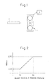
FIG. 1 is a view showing a rolling line used for Examples 1 and 2 of the present invention. -
FIG. 2 is a graph showing the relationship between the delivery thickness h and gain α used in Example 1 of the present invention. -
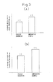
FIG. 3(a) is a graph showing the precision of the rolling force prediction, when predicting the rolling force as the rolling load, in Example 1 of the present invention. -
FIG. 3(b) is a graph showing the precision of the rolling torque prediction, when predicting the rolling torque as the rolling load, in Example 1 of the present invention. -
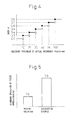
FIG. 4 is a graph showing the relationship between the delivery thickness of the actual pass h and a gain α used in Example 2 of the present invention. -
FIG. 5 is a graph showing the precision of the rolling force prediction in Example 1 of the present invention. -
FIG. 6 is a graph showing the thickness tolerance in Example 2 of the present invention. -
FIG. 7 is a graph showing the productivity in Example 2 of the present invention.. -
FIG. 8 is a view showing a rolling line used in Example 1 of the present invention. -
FIG. 9 is a graph showing the relationship between the delivery thickness at fifth stand h and a gain α used in Example 3 of the present invention. - Embodiments of the present invention will be explained using an example.
- This art is art able to be applied to prediction of all sorts of rolling load indicators such as the rolling force and the rolling torque. Here, as a preferred embodiment of the present invention, the example of the rolling force will be explained as one embodiment of the learning method in rolling load prediction.
- (Step-1) For any stock , as an indicator of the prediction error of rolling force at an actual pass, an error rate CP between an actual value of rolling force at an actual pass and the calculated value of rolling force at the actual pass is found based on formula (1).
- Here, as explained above, the "calculated value of the rolling force" means the rolling force, obtained by entering the actual values of the rolling conditions of the pass into a prediction formula of rolling force, multiplied with a learning coefficient of rolling force prediction for that pass.
- (Step-2) For the stock, the roiling force Pcal at a predicted pass performed after this is calculated using a rolling force model.
- (Step-3) For the stock, a gain α is found according to the thickness of the stock at the exit side of the rolling pass for which the rolling force was predicted at the above (Step-2). At this time, preferably the gain α is set to become larger, the greater the delivery thickness at the predicted pass of the stock. Note that, as the thickness of the stock, the entry thickness at the predicted pass, the entrythickness or delivery thickness at the actual pass, the delivery thickness at the final pass, etc. may be referred to so as to change the gain α.
- (Step-4) From the gain α calculated at the above (Step-3) and the prediction error rate CP of the rolling load at the actual pass found at the above (Step-1), formula (2) is used to calculate the learning coefficient CF of the rolling force at the predicted pass. Here, CF' is the learning coefficient of the rolling force at the actual path at the above (Step-1).

- (Step-5) Using the predicted value Pcal of the rolling force predicted at the above (Step-2) and the learning coefficient CF of the rolling force calculated at the above (Step-4), formula (3) is used to calculate the prediction of the rolling force for setting Pset at the predicted pass.

- (Step-6) Based on the prediction of the rolling force for setting Pset calculated at the above (Step-5), the rolling conditions at the rolling pass are set and rolling performed.
- Above, the process of learning of a rolling load in an embodiment of the present invention was shown, but in the present embodiment, the gain multiplied with the precision of the rolling load prediction is adjusted in an actual pass in the rolling load prediction in accordance with the magnitude of the thickness of the stock, so it is possible to improve the precision of the rolling load prediction more stably than the past. Further, due to this, the thickness, crown, and flatness of the rolled products can be made closer to the desired values, so the advantageous effects are obtained that the yield loss in rolling is suppressed and the productivity is improved.
- Below, an example of the present invention will be explained based on the drawings. Note that, the numerical values, functions, etc. used in the following examples are nothing more than illustrations for explaining the present invention. The present invention is not limited to the following examples. Note that component elements having substantially the same functional configurations in the Description and Drawings are assigned the same reference signs and overlapping explanations are omitted.
- Consider an example applying the present invention to inter-pass learning for rolling force prediction and rolling torque prediction in reverse multi-pass type rolling by a rolling
mill 1 shown inFIG. 1 . In the rollingmill 1, thestock 2 has already been rolled by an (i-1)-th pass and is about to be rolled at an i-th pass. At this time, the rolling force Pexp i-1 and rolling torque Gexp i-1 at the (i-1)-th pass and the entry thickness Hi-1, the delivery thickness hi-1, and the rolling temperature Ti-1 of thestock 2 are stored in theprocessing unit 3. Further, theprocessing unit 3 stores the work roll radius R of the rollingmill 1 and the material components of the stock and width w of thestock 2 - Below, the case will be shown of referring to the prediction error rates of the rolling force and rolling torque at the (i-1)-th pass to correct the predicted values of the rolling force and rolling torque at the i-th pass.
- The
processing unit 3 first calculates the deformation resistance ki-1 at an actual pass of thestock 2, that is, the (i-1)-th pass. In general, the deformation resistance ki-1 at the (i-1)-th pass is given by a function using at least the material components of the stock and rolling temperature Ti-1 of the rolling material as arguments. - Next, the
processing unit 3 will be used to calculate the flattened roll radius R'i-1 at the (i-1)-th pass. In the present example, formula (4) was used.
- Here, CH is the Hitchcock coefficient. Further, H and h are the entry and delivery thicknesses of the pass, while P is the rolling force at the pass. Here, the entry thickness Hi-1, delivery thickness hi-1, and actual force Pexp i-1 at the (i-1)-th pass were inputted.
- Furthermore, the
processing unit 3 is used to use formulas (5) and (5)' to calculate the calculated value Pcal i-1 of the rolling force and the calculated value Gcal i-1 of the rolling torque at the (i-1)-th pass.

- Here, Q is the rolling force function at the pass, while λ is the torque arm coefficient. Furthermore, from the actual measured value Pexp i-1 of the rolling force at the (i-1)-th pass and the calculated value Pcal i-1 of the rolling force at the (i-1)-th pass, based on formula (1), the error rate CP(P) of the rolling force at the actual pass ((i-1)-th pass) is found. Similarly, from the actual measured value Gexp i-1 of the rolling torque at the (i-1)-th pass and the calculated value Gcal i-1 of the rolling torque at the (i-1)-th pass, based on formula (1), the error rate CP(G) of the rolling torque at the actual pass ((i-1)-th pass) is found.
- Next, from the rolling conditions for the i-th pass of the predicted pass of the rolling
material 2, the predicted values of the rolling force and rolling torque at the predicted pass are calculated. This can be found by inputting the i-th pass entry thickness Hi, delivery thickness hi, rolling temperature Ti, etc. into formulas (4) to (5)'. - Furthermore, referring to formula (6), for setting the learning coefficient for rolling load prediction, the gain α multiplied with the prediction error rates of the rolling force and rolling torque at an actual pass is found. In the present example, as shown in formula (6), the gain α was changed in accordance with the delivery thickness h of the predicted pass (i-th pass).

- Here, the unit of the delivery thickness at the predicted pass h is mm. Note that, the relationship between the delivery thickness at the predicted pass h and the gain α based on formula (6) is shown in
FIG. 2 as well. - Finally, the gain α determined by the formula (6) is used with formula (2) to calculate the learning coefficient CF(P) of the rolling force and the learning coefficient CF(G) of the rolling torque at the predicted pass. Based on this and the predicted value Pcal of the rolling force and the predicted value Gcal of the rolling torque, formula (3) is used to calculate the prediction of the rolling force for setting Pset and the prediction of the rolling torque for setting Gset at the i-th pass.
- When using the formula (3) when calculating the prediction of the rolling torque for setting Gset, it is possible to enter the predicted value of the rolling torque Gcal instead of the predicted value of the rolling force Pcal and enter the learning coefficient CF(G) of the rolling torque instead of the learning coefficient CF(P) of the rolling force.
- By setting the roll gap, crown control amount, and rolling speed based on the prediction of the rolling force for setting Pset and the prediction of the rolling torque for setting Gset found at formula (3), the
stock 2 is rolled by the i-th pass. - In this way, when predicting the rolling force and rolling torque at a rolling pass to be performed from, then (predicted pass) based on the rolling force at an actually performed rolling pass (actual pass) and also the actual value and the calculated value of the rolling torque, the gain multiplied with the rolling force prediction error rate and rolling torque prediction error rate of the rolling force prediction and rolling torque prediction at the actual pass was changed in accordance with the delivery thickness of the
stock 2 at the predicted pass. - As a comparative example, the gain was made constant (α=0.5) regardless of the delivery thickness of the
stock 2 at the predicted pass and the prediction errors of the rolling force and rolling torque were compared. Note that this was applied to rolling of 100 units for comparison. - The results are shown in
FIG. 3(a) and FIG. 3(b) . In the comparative example, the standard deviation σ of rolling force prediction was 8.6% and the standard deviation σ of rolling torque prediction was 12.1%, while in the present example, the standard deviation σ of rolling force prediction was 4.2% and the standard deviation σ of rolling torque prediction was 7.7%, that is, values greatly reduced from the comparative example. Due to this, in the present example, the precision of the rolling force prediction and rolling torque prediction was improved, so it was possible to precisely set the roll gap, crown control amount, and rolling speed at each rolling pass and therefore the precision of thickness, crown, and flatness of the rolled products could be greatly improved. - Here, the explanation was given of the example of the case of use of the rolling force and rolling torque for the indicators to be predicted, but the present invention is not limited to prediction of the rolling force and rolling torque. For example, it may also be applied to prediction of the rolling power and other various rolling load indicators. That is, the present invention is not limited to the above examples. The rolling load indicators may be changed in various ways within a scope not exceeding the gist of the invention.
- Further, in the present example, the explanation was given as an example of the case of use of the actual result in the immediately preceding rolling pass to improve the precision of the rolling load prediction in the immediately succeeding rolling pass, but, for example, the present invention may also be applied to the case of using not only the actual result in the immediately preceding rolling pass, but also the actual result of an already performed single rolling pass, or two or more rolling passes and/or the case of improving not only the precision of the rolling load prediction at the immediately succeeding rolling pass, but also that of a subsequently performed single rolling pass or, two or more rolling passes.
- In addition, in the present example, the explanation was given of the example of the case of referring to the delivery thickness of the stock at the predicted pass, but the present invention is not limited to the delivery thickness of the stock at the predicted pass, for example, the entry thickness at the predicted pass, the entry thickness or delivery thickness at the actual pass, the delivery thickness at the final pass, or a combination of the same etc. may also be used.
- Example 2, like Example 1, applies the present invention to inter-pass learning of rolling force prediction in reverse type multi-pass rolling by the rolling
mill 1 shown inFIG. 1 . In the present example, as shown in formula (7), the gain α was changed in accordance with the referred to the delivery thickness h at the actual pass.
- Note that, the relationship between the delivery thickness h at the actual pass and gain α based on formula (7) is shown in
FIG. 4 as well. Further, at each rolling pass, the learning coefficient at the rolling force prediction at the following rolling passes was updated so as to correct the draft schedule and crown control amount at the subsequent passes. In this way, a hot steel plates were rolled with initial thickness of 40.0 to 200.0 mm, delivery thickness at the final pass of 4.0 to 150.0 mm, a width of 1200 to 4800 mm, and a total number of rolling passes of 4 to 15. - As a comparative example, the gain was made constant (α=0.5) regardless of the delivery thickness of the
stock 2 at the actual and rolling performed in a similar way. Note that, this was applied to 100 rolling materials. - As a result, as shown in
FIG. 5 , in the comparative example, the standard deviation of rolling force prediction σ was 7.0%, while in the present example, the standard deviation of rolling force prediction σ was 2.8%. Much reduced from the comparative example. - Further, in the present example, the precision of the rolling force prediction was improved, so it was possible to precisely set the roll gap and crown control amount at each rolling pass, therefore, as shown in
FIG. 6 , delivery thickness tolerance of the stock at the final pass (average of the variation from target value) was 0.149 mm in the comparative example, while was greatly improved to 0.077 mm in the present example. - Furthermore, due to the improvement of precision of the rolling force prediction, the crown tolerance was also improved, so the flatness could be greatly improved and the rate of occurrence of troubles due to poor flatness could be greatly reduced, so, as shown in
FIG. 7 , the productivity (amount of rolling products per hour) was 182 tonf/h in the comparative example, while was improved to 191 tonf/h in the present example. - Example 3 is an example of application of the present art to a tandem rolling process of hot strip with a final stand delivery thickness of 1.0 to 20.0 mm.
- As shown in
FIG. 8 , consider the example of application of the present invention to inter-pass learning of rolling force prediction in tandem rolling in a group of rolling mills 4 comprised of fiverolling mills 4a to 4e. In the group of rolling mills 4, thestock 2 is already rolled by thefirst stand 4a and is about to be rolled by thesecond stand 4b to thefifth stand 4e. At this time, the rolling force Pexp 1 at the first stand, the entry thickness H1 of thestock 2, the delivery thickness h1, and the rolling temperature T1 are stored in theprocessing unit 3. Further, theprocessing unit 3 also stores the work roll radius R of thestands 4a to 4e of the group of rolling mills 4 and the material components and width w of thestock 2. - Here, it may be considered to use the prediction error of rolling force at the first stand to correct the predicted value of the rolling force at the second to fifth stands.
- The
processing unit 3, first, calculates the material deformation resistance k1 at the first stand of thestock 2. Next, theprocessing unit 3 is used to calculate the flattened roll radius R'1. Furthermore, theprocessing unit 3 is used to calculate, by formula (5), the calculated value of the rolling force Pcal 1. Finally, it finds the error rate CP of the rolling force from the actual measured value of the rolling force Pexp 1 and the calculated value of the rolling force Pcal 1 based on formula (1) and calculates the learning coefficient of rolling force prediction CF at the subsequent rolling passes by formula (2). - Next, the unit calculates the predicted value of the rolling force at subsequent rolling stands for rolling the
stock 2 from the rolling conditions for the rolling stand. This can be found, as shown in Example 1, by inputting the entry thickness Hi, delivery thickness hi, and rolling temperature Ti (suffix i shows value is for i-th stand, same below), etc. for each stand into formulas (4) to (5). - Furthermore, based on the delivery thickness hi of each stand, it refers to formula (8) and finds the gain α for multiplication with the prediction error of the rolling force rate at an actual pass for the rolling force prediction for each stand. In the present example, the gain α was changed in accordance with delivery thickness at the fifth stand h.

- Here, the unit of the delivery thickness at the fifth stand h is mm. Note that, the relationship of the delivery thickness at the fifth stand h and the gain α based on formula (8) is shown in
FIG. 9 . - Finally, the gain α determined at formula (8) was used to correct the predicted value of the rolling force Pcal so as to calculate the prediction of the rolling force for setting Pset based on formula (3). By setting the roll gap and crown control amount based on the prediction of the rolling force for setting Pset obtained, the
stock 2 was rolled at thesecond stand 4b tofifth stand 4e of the group of rolling mills 4. - As a comparative example, the learning gain was made constant (α=0.3) regardless of the delivery thickness at the fifth stand of the
stock 2. Note that, this was applied to 200 rolling materials each. - As a result, in the comparative example, the standard deviation of rolling force prediction σ was 3.1%, while in the present example, the standard deviation of rolling force prediction σ was greatly improved to 1.9%.
- According to the present invention, in hot rolling, it is possible to improve the precision of the rolling load prediction more stably than the past. Further, due to this, it is possible to make the thickness, crown, and flatness of the rolled products closer to the desired values, so the effects are also obtained that the yield loss in rolling is suppressed and the productivity is improved. For this reason, the present invention will contribute to the efficient production of ferrous metal materials and will of course have ripple effects not only in the ferrous metal industry of course, but also the automobile industry etc. using a broad range of ferrous metal products.
-
- 1.
- rolling mill
- 2.
- stock
- 3.
- processing unit
- 4.
- group of rolling mills
- 4a.
- first stand of group of rolling mills 4
- 4b.
- second stand of group of rolling mills 4
- 4c.
- third stand of group of rolling mills 4
- 4d.
- fourth stand of group of rolling mills 4
- 4e.
- fifth stand of group of rolling mills 4
Claims (8)
- A learning method of rolling load prediction for hot rolling referring to prediction error of a rolling load at an actual pass of a stock to correct a predicted value of rolling load at a rolling pass of said stock to be performed from then on,
said learning method of rolling load prediction for hot rolling characterized by, when setting a learning coefficient for rolling load prediction, changing a gain multiplied with the prediction error of the rolling load at said actual pass in accordance with a thickness of said stock. - A learning method of rolling load prediction as set forth in claim 1, characterized by, when setting a learning coefficient for rolling load prediction, making the gain multiplied with the prediction error of the rolling load at said actual pass smaller the smaller said thickness of the stock.
- A learning method of rolling load prediction as set forth in claim 1 or 2, characterized by changing the gain multiplied with the prediction error of the rolling load at said actual pass in accordance with the thickness of the stock at an actual pass.
- A learning method of rolling load prediction as set forth in claim 1 or 2, characterized by changing the gain multiplied with the prediction error of the rolling load at said actual pass in accordance with the thickness of the stock at the predicted pass.
- A learning method of rolling load prediction as set forth in claim 1 or 2, characterized by changing the gain multiplied with the prediction error of the rolling load at said actual pass in accordance with the thickness of the stock at a final pass.
- A learning method of rolling load prediction as set forth in any one of claims 1 to 5, characterized in that the thickness used as the reference for changing the gain multiplied with the prediction error of the rolling load at said actual pass is one obtained from one or more of an entry thickness, delivery thickness, and average thickness in combination.
- A learning method of rolling load prediction as set forth in any one of claims 1 to 6, characterized in that said rolling load is a rolling force.
- A learning method of rolling load prediction as set forth in any one of claims 1 to 7, characterized in that said rolling load is a rolling torque.
Applications Claiming Priority (2)
| Application Number | Priority Date | Filing Date | Title |
|---|---|---|---|
| JP2008066712 | 2008-03-14 | ||
| PCT/JP2009/055364 WO2009113719A1 (en) | 2008-03-14 | 2009-03-12 | Rolling load prediction learning method for hot plate rolling |
Publications (3)
| Publication Number | Publication Date |
|---|---|
| EP2145703A1 true EP2145703A1 (en) | 2010-01-20 |
| EP2145703A4 EP2145703A4 (en) | 2013-10-02 |
| EP2145703B1 EP2145703B1 (en) | 2015-01-07 |
Family
ID=41065370
Family Applications (1)
| Application Number | Title | Priority Date | Filing Date |
|---|---|---|---|
| EP09720988.6A Not-in-force EP2145703B1 (en) | 2008-03-14 | 2009-03-12 | Rolling load prediction learning method for hot plate rolling |
Country Status (7)
| Country | Link |
|---|---|
| US (1) | US8185232B2 (en) |
| EP (1) | EP2145703B1 (en) |
| JP (1) | JP4452323B2 (en) |
| KR (1) | KR101149927B1 (en) |
| CN (1) | CN101678417B (en) |
| BR (1) | BRPI0903494A2 (en) |
| WO (1) | WO2009113719A1 (en) |
Cited By (1)
| Publication number | Priority date | Publication date | Assignee | Title |
|---|---|---|---|---|
| EP3928885A4 (en) * | 2019-02-21 | 2022-04-06 | JFE Steel Corporation | ROLLING LOAD PREDICTION METHOD, ROLLING LOAD PREDICTION DEVICE AND ROLLING CONTROL METHOD |
Families Citing this family (25)
| Publication number | Priority date | Publication date | Assignee | Title |
|---|---|---|---|---|
| CN101977855B (en) | 2008-03-21 | 2015-07-29 | 加利福尼亚技术学院 | Metallic glass formed by discharging a flying capacitor |
| US8613816B2 (en) | 2008-03-21 | 2013-12-24 | California Institute Of Technology | Forming of ferromagnetic metallic glass by rapid capacitor discharge |
| US8613814B2 (en) | 2008-03-21 | 2013-12-24 | California Institute Of Technology | Forming of metallic glass by rapid capacitor discharge forging |
| US8499598B2 (en) | 2010-04-08 | 2013-08-06 | California Institute Of Technology | Electromagnetic forming of metallic glasses using a capacitive discharge and magnetic field |
| CN103328675B (en) * | 2010-12-23 | 2016-01-06 | 加利福尼亚技术学院 | Formed by the sheet material of the metallic glass of rapid capacitor discharge |
| JP5939545B2 (en) | 2011-02-16 | 2016-06-22 | カリフォルニア インスティチュート オブ テクノロジー | Injection molding of metallic glass by rapid capacitor discharge |
| JP5759206B2 (en) * | 2011-03-01 | 2015-08-05 | 東芝三菱電機産業システム株式会社 | Learning coefficient controller |
| WO2012127571A1 (en) * | 2011-03-18 | 2012-09-27 | 株式会社 日立製作所 | Rolling control apparatus, rolling control method, and rolling control program |
| US9393612B2 (en) | 2012-11-15 | 2016-07-19 | Glassimetal Technology, Inc. | Automated rapid discharge forming of metallic glasses |
| WO2014145747A1 (en) | 2013-03-15 | 2014-09-18 | Glassimetal Technology, Inc. | Methods for shaping high aspect ratio articles from metallic glass alloys using rapid capacitive discharge and metallic glass feedstock for use in such methods |
| US10273568B2 (en) | 2013-09-30 | 2019-04-30 | Glassimetal Technology, Inc. | Cellulosic and synthetic polymeric feedstock barrel for use in rapid discharge forming of metallic glasses |
| CN104630661B (en) | 2013-10-03 | 2017-04-26 | 格拉斯金属技术股份有限公司 | Feedstock barrels coated with insulating films for rapid discharge forming of metallic glasses |
| US10029304B2 (en) | 2014-06-18 | 2018-07-24 | Glassimetal Technology, Inc. | Rapid discharge heating and forming of metallic glasses using separate heating and forming feedstock chambers |
| US10022779B2 (en) | 2014-07-08 | 2018-07-17 | Glassimetal Technology, Inc. | Mechanically tuned rapid discharge forming of metallic glasses |
| JP6315818B2 (en) * | 2014-10-07 | 2018-04-25 | 株式会社日立製作所 | Control device and control method for tandem rolling mill |
| BR112017011610B1 (en) * | 2015-03-10 | 2022-12-13 | Toshiba Mitsubishi-Electric Industrial Systems Corporation | PLATE WIDTH CONTROL DEVICE FOR MATERIAL TO BE LAMINATED |
| US10682694B2 (en) | 2016-01-14 | 2020-06-16 | Glassimetal Technology, Inc. | Feedback-assisted rapid discharge heating and forming of metallic glasses |
| US10632529B2 (en) | 2016-09-06 | 2020-04-28 | Glassimetal Technology, Inc. | Durable electrodes for rapid discharge heating and forming of metallic glasses |
| JP6670261B2 (en) * | 2017-02-23 | 2020-03-18 | 株式会社日立製作所 | Tandem rolling mill control device and tandem rolling mill control method |
| KR20190078323A (en) * | 2017-12-26 | 2019-07-04 | 주식회사 포스코 | Load distribution setting apparatus of finishing mill |
| CN108346009B (en) * | 2018-03-21 | 2021-09-03 | 深圳库博能源科技有限公司 | Power production configuration method and device based on user model self-learning |
| JP7070796B2 (en) * | 2019-09-12 | 2022-05-18 | 東芝三菱電機産業システム株式会社 | Aperture generation prediction system |
| CN113426838A (en) * | 2021-06-29 | 2021-09-24 | 李炳集 | Secondary system of new generation of medium plate steckel mill and application method thereof |
| US12569898B2 (en) * | 2021-12-24 | 2026-03-10 | Tmeic Corporation | Tail end buckling suppression device |
| TWI798047B (en) * | 2022-04-08 | 2023-04-01 | 中國鋼鐵股份有限公司 | Method for predicting rolling force of steel plate and rolling system |
Family Cites Families (26)
| Publication number | Priority date | Publication date | Assignee | Title |
|---|---|---|---|---|
| US3713313A (en) * | 1971-11-19 | 1973-01-30 | Gen Electric | Computer controlled rolling mill |
| JPS538305B2 (en) | 1974-02-01 | 1978-03-27 | ||
| JPS58141807A (en) * | 1982-02-15 | 1983-08-23 | Mitsubishi Electric Corp | Equipment for automatically controlling sheet thickness |
| JPS58163517A (en) * | 1982-03-25 | 1983-09-28 | Mitsubishi Heavy Ind Ltd | Method and device for controlling sheet thickness in rolling mill |
| JPS61235017A (en) * | 1985-04-10 | 1986-10-20 | Kawasaki Steel Corp | Forecasting method for spindle torque of rolling mill |
| JPS6240925A (en) * | 1985-08-16 | 1987-02-21 | Kobe Steel Ltd | Control method for plate thickness |
| JPH0661566B2 (en) | 1987-11-18 | 1994-08-17 | 株式会社日立製作所 | Rolling mill setup device |
| JPH0576917A (en) * | 1991-09-18 | 1993-03-30 | Nkk Corp | Method for controlling thickness of thick plate |
| US6377864B1 (en) * | 1994-06-16 | 2002-04-23 | Finn-Power International, Inc. | System and method of flexibly sorting and unloading finished parts during part manufacturing process |
| JPH0852506A (en) * | 1994-08-11 | 1996-02-27 | Yaskawa Electric Corp | Skin pass mill tension control method and device |
| DE19505694C1 (en) * | 1995-02-20 | 1996-07-04 | Siemens Ag | Appts. for controlling the thickness of rolled material |
| JP3607029B2 (en) * | 1997-01-16 | 2005-01-05 | 東芝三菱電機産業システム株式会社 | Rolling mill control method and control apparatus |
| JP3237559B2 (en) * | 1997-02-07 | 2001-12-10 | 住友金属工業株式会社 | Thickness control method of hot continuous rolling mill |
| JP3467677B2 (en) | 1997-03-25 | 2003-11-17 | Jfeスチール株式会社 | Learning control method of rolling load in rolling mill |
| JP3495909B2 (en) * | 1998-03-30 | 2004-02-09 | 株式会社東芝 | Roll roll profile control device |
| FR2783444B1 (en) * | 1998-09-21 | 2000-12-15 | Kvaerner Metals Clecim | LAMINATION PROCESS OF A METAL PRODUCT |
| JP2000126809A (en) | 1998-10-27 | 2000-05-09 | Kobe Steel Ltd | Set up device of rolling mill |
| JP2005527378A (en) * | 2002-03-15 | 2005-09-15 | シーメンス アクチエンゲゼルシヤフト | Computer-aided decision method for target values for profile and flatness control elements |
| CN1267215C (en) * | 2002-11-20 | 2006-08-02 | Posco株式会社 | Fault diagnosis apparatus and method for hot fine rolling band steel |
| DE10300374B4 (en) * | 2003-01-06 | 2010-12-23 | Windmöller & Hölscher Kg | Method and device for controlling the thickness of extruded film |
| US7050875B2 (en) * | 2003-07-01 | 2006-05-23 | General Electric Company | System and method for detecting an anomalous condition |
| WO2006008808A1 (en) * | 2004-07-20 | 2006-01-26 | Toshiba Mitsubishi-Electric Industrial Systems Corporation | Method of setting/controlling wedge in plate material rolling |
| JP2006095592A (en) * | 2004-09-30 | 2006-04-13 | Jfe Steel Kk | Elongation rate control method in temper rolling mill |
| JP4437753B2 (en) * | 2005-02-18 | 2010-03-24 | 東芝三菱電機産業システム株式会社 | Thickness control method for tandem rolling mill |
| JP4988171B2 (en) * | 2005-06-23 | 2012-08-01 | 株式会社日立製作所 | Rolling mill control device |
| CN100474313C (en) * | 2005-10-31 | 2009-04-01 | 宝山钢铁股份有限公司 | A Method for Optimal Setting of Rough Strip Width |
-
2009
- 2009-03-12 EP EP09720988.6A patent/EP2145703B1/en not_active Not-in-force
- 2009-03-12 KR KR1020097024046A patent/KR101149927B1/en not_active Expired - Fee Related
- 2009-03-12 BR BRPI0903494A patent/BRPI0903494A2/en not_active Application Discontinuation
- 2009-03-12 CN CN2009800003774A patent/CN101678417B/en not_active Expired - Fee Related
- 2009-03-12 US US12/451,037 patent/US8185232B2/en not_active Expired - Fee Related
- 2009-03-12 WO PCT/JP2009/055364 patent/WO2009113719A1/en not_active Ceased
- 2009-03-12 JP JP2009531654A patent/JP4452323B2/en not_active Expired - Fee Related
Cited By (2)
| Publication number | Priority date | Publication date | Assignee | Title |
|---|---|---|---|---|
| EP3928885A4 (en) * | 2019-02-21 | 2022-04-06 | JFE Steel Corporation | ROLLING LOAD PREDICTION METHOD, ROLLING LOAD PREDICTION DEVICE AND ROLLING CONTROL METHOD |
| US12145184B2 (en) | 2019-02-21 | 2024-11-19 | Jfe Steel Corporation | Rolling load prediction method, rolling load prediction device, and rolling control method |
Also Published As
| Publication number | Publication date |
|---|---|
| JPWO2009113719A1 (en) | 2011-07-21 |
| US8185232B2 (en) | 2012-05-22 |
| US20100121471A1 (en) | 2010-05-13 |
| JP4452323B2 (en) | 2010-04-21 |
| CN101678417B (en) | 2013-11-20 |
| CN101678417A (en) | 2010-03-24 |
| KR101149927B1 (en) | 2012-06-08 |
| WO2009113719A1 (en) | 2009-09-17 |
| EP2145703B1 (en) | 2015-01-07 |
| EP2145703A4 (en) | 2013-10-02 |
| BRPI0903494A2 (en) | 2015-09-22 |
| KR20090130410A (en) | 2009-12-23 |
Similar Documents
| Publication | Publication Date | Title |
|---|---|---|
| EP2145703B1 (en) | Rolling load prediction learning method for hot plate rolling | |
| CN104942019B (en) | A kind of cold rolling of strip steel process Automatic control method of width | |
| US8676371B2 (en) | Rolling of a strip in a rolling train using the last stand of the rolling train as a tension reducer | |
| CN1243047A (en) | Interlinked control method for plate-band rolling course based on coordination law of plate shape and plate thickness | |
| JP2002126813A (en) | Setting method of rolling leveling in sheet rolling | |
| JP2009022985A (en) | Shape control method in cold rolling | |
| JP4671544B2 (en) | Sheet width control method in cold tandem rolling | |
| JP6232193B2 (en) | Shape control method and shape control method in cold rolling | |
| JP4330134B2 (en) | Shape control method in cold rolling | |
| RU2288792C1 (en) | Carbon steel strip cold rolling process | |
| Shalaevskiy et al. | Algorithm and design methodology for energy-efficient sheet products production technology | |
| WO2022214527A1 (en) | Apparatus for continuous monitoring of a metallic material in a rolling process, and related method for continuous monitoring of a metallic material in a rolling process | |
| JP2019055415A (en) | Plate crown control method, plate crown control device, and steel plate manufacturing method | |
| JP2003290807A (en) | Method for controlling sheet width in tandem cold rolling | |
| JP4813014B2 (en) | Shape control method for cold tandem rolling mill | |
| JP2002028708A (en) | Steel plate and plate manufacturing method and plate manufacturing equipment | |
| JP7685721B2 (en) | Control and setting method of plate wedge in hot reversible plate rolling | |
| JP4102267B2 (en) | Sheet width control method in cold tandem rolling | |
| JP6252609B2 (en) | Tension control method for cold rolling mill and method for manufacturing cold rolled steel sheet | |
| JP2968645B2 (en) | Strip width control method in hot rolling | |
| JP2005296985A (en) | Sheet crown and shape control method in sheet rolling | |
| JP7103329B2 (en) | Rolling mill control method and control device | |
| Kozhevnikov | The Development and Application of Methodologies for the Design of Technological Modes of Cold Rolling | |
| JP2005319492A (en) | Method for controlling shape in cold rolling | |
| JP4140316B2 (en) | Metal plate manufacturing method |
Legal Events
| Date | Code | Title | Description |
|---|---|---|---|
| PUAI | Public reference made under article 153(3) epc to a published international application that has entered the european phase |
Free format text: ORIGINAL CODE: 0009012 |
|
| 17P | Request for examination filed |
Effective date: 20091103 |
|
| AK | Designated contracting states |
Kind code of ref document: A1 Designated state(s): AT BE BG CH CY CZ DE DK EE ES FI FR GB GR HR HU IE IS IT LI LT LU LV MC MK MT NL NO PL PT RO SE SI SK TR |
|
| AX | Request for extension of the european patent |
Extension state: AL BA RS |
|
| DAX | Request for extension of the european patent (deleted) | ||
| RAP1 | Party data changed (applicant data changed or rights of an application transferred) |
Owner name: NIPPON STEEL & SUMITOMO METAL CORPORATION |
|
| A4 | Supplementary search report drawn up and despatched |
Effective date: 20130830 |
|
| RIC1 | Information provided on ipc code assigned before grant |
Ipc: B21B 37/00 20060101AFI20130826BHEP |
|
| GRAP | Despatch of communication of intention to grant a patent |
Free format text: ORIGINAL CODE: EPIDOSNIGR1 |
|
| INTG | Intention to grant announced |
Effective date: 20140618 |
|
| GRAS | Grant fee paid |
Free format text: ORIGINAL CODE: EPIDOSNIGR3 |
|
| RIN1 | Information on inventor provided before grant (corrected) |
Inventor name: IGARASHI, KAZUTSUGU Inventor name: HIGO, TSUYOSHI Inventor name: FUKUOKA, YASUSHI Inventor name: MIZOGUCHI, YOSUKE |
|
| GRAA | (expected) grant |
Free format text: ORIGINAL CODE: 0009210 |
|
| AK | Designated contracting states |
Kind code of ref document: B1 Designated state(s): AT BE BG CH CY CZ DE DK EE ES FI FR GB GR HR HU IE IS IT LI LT LU LV MC MK MT NL NO PL PT RO SE SI SK TR |
|
| REG | Reference to a national code |
Ref country code: GB Ref legal event code: FG4D |
|
| REG | Reference to a national code |
Ref country code: CH Ref legal event code: EP |
|
| REG | Reference to a national code |
Ref country code: IE Ref legal event code: FG4D |
|
| REG | Reference to a national code |
Ref country code: AT Ref legal event code: REF Ref document number: 705333 Country of ref document: AT Kind code of ref document: T Effective date: 20150215 |
|
| REG | Reference to a national code |
Ref country code: DE Ref legal event code: R096 Ref document number: 602009028811 Country of ref document: DE Effective date: 20150219 |
|
| REG | Reference to a national code |
Ref country code: NL Ref legal event code: VDEP Effective date: 20150107 |
|
| REG | Reference to a national code |
Ref country code: AT Ref legal event code: MK05 Ref document number: 705333 Country of ref document: AT Kind code of ref document: T Effective date: 20150107 |
|
| REG | Reference to a national code |
Ref country code: LT Ref legal event code: MG4D |
|
| PG25 | Lapsed in a contracting state [announced via postgrant information from national office to epo] |
Ref country code: NO Free format text: LAPSE BECAUSE OF FAILURE TO SUBMIT A TRANSLATION OF THE DESCRIPTION OR TO PAY THE FEE WITHIN THE PRESCRIBED TIME-LIMIT Effective date: 20150407 Ref country code: FI Free format text: LAPSE BECAUSE OF FAILURE TO SUBMIT A TRANSLATION OF THE DESCRIPTION OR TO PAY THE FEE WITHIN THE PRESCRIBED TIME-LIMIT Effective date: 20150107 Ref country code: HR Free format text: LAPSE BECAUSE OF FAILURE TO SUBMIT A TRANSLATION OF THE DESCRIPTION OR TO PAY THE FEE WITHIN THE PRESCRIBED TIME-LIMIT Effective date: 20150107 Ref country code: SE Free format text: LAPSE BECAUSE OF FAILURE TO SUBMIT A TRANSLATION OF THE DESCRIPTION OR TO PAY THE FEE WITHIN THE PRESCRIBED TIME-LIMIT Effective date: 20150107 Ref country code: BG Free format text: LAPSE BECAUSE OF FAILURE TO SUBMIT A TRANSLATION OF THE DESCRIPTION OR TO PAY THE FEE WITHIN THE PRESCRIBED TIME-LIMIT Effective date: 20150407 Ref country code: LT Free format text: LAPSE BECAUSE OF FAILURE TO SUBMIT A TRANSLATION OF THE DESCRIPTION OR TO PAY THE FEE WITHIN THE PRESCRIBED TIME-LIMIT Effective date: 20150107 Ref country code: ES Free format text: LAPSE BECAUSE OF FAILURE TO SUBMIT A TRANSLATION OF THE DESCRIPTION OR TO PAY THE FEE WITHIN THE PRESCRIBED TIME-LIMIT Effective date: 20150107 |
|
| PG25 | Lapsed in a contracting state [announced via postgrant information from national office to epo] |
Ref country code: LV Free format text: LAPSE BECAUSE OF FAILURE TO SUBMIT A TRANSLATION OF THE DESCRIPTION OR TO PAY THE FEE WITHIN THE PRESCRIBED TIME-LIMIT Effective date: 20150107 Ref country code: AT Free format text: LAPSE BECAUSE OF FAILURE TO SUBMIT A TRANSLATION OF THE DESCRIPTION OR TO PAY THE FEE WITHIN THE PRESCRIBED TIME-LIMIT Effective date: 20150107 Ref country code: PL Free format text: LAPSE BECAUSE OF FAILURE TO SUBMIT A TRANSLATION OF THE DESCRIPTION OR TO PAY THE FEE WITHIN THE PRESCRIBED TIME-LIMIT Effective date: 20150107 Ref country code: GR Free format text: LAPSE BECAUSE OF FAILURE TO SUBMIT A TRANSLATION OF THE DESCRIPTION OR TO PAY THE FEE WITHIN THE PRESCRIBED TIME-LIMIT Effective date: 20150408 Ref country code: IS Free format text: LAPSE BECAUSE OF FAILURE TO SUBMIT A TRANSLATION OF THE DESCRIPTION OR TO PAY THE FEE WITHIN THE PRESCRIBED TIME-LIMIT Effective date: 20150507 Ref country code: NL Free format text: LAPSE BECAUSE OF FAILURE TO SUBMIT A TRANSLATION OF THE DESCRIPTION OR TO PAY THE FEE WITHIN THE PRESCRIBED TIME-LIMIT Effective date: 20150107 |
|
| REG | Reference to a national code |
Ref country code: DE Ref legal event code: R097 Ref document number: 602009028811 Country of ref document: DE |
|
| PG25 | Lapsed in a contracting state [announced via postgrant information from national office to epo] |
Ref country code: RO Free format text: LAPSE BECAUSE OF FAILURE TO SUBMIT A TRANSLATION OF THE DESCRIPTION OR TO PAY THE FEE WITHIN THE PRESCRIBED TIME-LIMIT Effective date: 20150107 Ref country code: EE Free format text: LAPSE BECAUSE OF FAILURE TO SUBMIT A TRANSLATION OF THE DESCRIPTION OR TO PAY THE FEE WITHIN THE PRESCRIBED TIME-LIMIT Effective date: 20150107 Ref country code: DK Free format text: LAPSE BECAUSE OF FAILURE TO SUBMIT A TRANSLATION OF THE DESCRIPTION OR TO PAY THE FEE WITHIN THE PRESCRIBED TIME-LIMIT Effective date: 20150107 Ref country code: SK Free format text: LAPSE BECAUSE OF FAILURE TO SUBMIT A TRANSLATION OF THE DESCRIPTION OR TO PAY THE FEE WITHIN THE PRESCRIBED TIME-LIMIT Effective date: 20150107 Ref country code: LU Free format text: LAPSE BECAUSE OF FAILURE TO SUBMIT A TRANSLATION OF THE DESCRIPTION OR TO PAY THE FEE WITHIN THE PRESCRIBED TIME-LIMIT Effective date: 20150312 Ref country code: MC Free format text: LAPSE BECAUSE OF FAILURE TO SUBMIT A TRANSLATION OF THE DESCRIPTION OR TO PAY THE FEE WITHIN THE PRESCRIBED TIME-LIMIT Effective date: 20150107 Ref country code: CZ Free format text: LAPSE BECAUSE OF FAILURE TO SUBMIT A TRANSLATION OF THE DESCRIPTION OR TO PAY THE FEE WITHIN THE PRESCRIBED TIME-LIMIT Effective date: 20150107 |
|
| REG | Reference to a national code |
Ref country code: CH Ref legal event code: PL |
|
| PLBE | No opposition filed within time limit |
Free format text: ORIGINAL CODE: 0009261 |
|
| STAA | Information on the status of an ep patent application or granted ep patent |
Free format text: STATUS: NO OPPOSITION FILED WITHIN TIME LIMIT |
|
| 26N | No opposition filed |
Effective date: 20151008 |
|
| PG25 | Lapsed in a contracting state [announced via postgrant information from national office to epo] |
Ref country code: IT Free format text: LAPSE BECAUSE OF FAILURE TO SUBMIT A TRANSLATION OF THE DESCRIPTION OR TO PAY THE FEE WITHIN THE PRESCRIBED TIME-LIMIT Effective date: 20150107 |
|
| REG | Reference to a national code |
Ref country code: IE Ref legal event code: MM4A |
|
| PG25 | Lapsed in a contracting state [announced via postgrant information from national office to epo] |
Ref country code: LI Free format text: LAPSE BECAUSE OF NON-PAYMENT OF DUE FEES Effective date: 20150331 Ref country code: CH Free format text: LAPSE BECAUSE OF NON-PAYMENT OF DUE FEES Effective date: 20150331 Ref country code: IE Free format text: LAPSE BECAUSE OF NON-PAYMENT OF DUE FEES Effective date: 20150312 |
|
| REG | Reference to a national code |
Ref country code: FR Ref legal event code: PLFP Year of fee payment: 8 |
|
| PG25 | Lapsed in a contracting state [announced via postgrant information from national office to epo] |
Ref country code: SI Free format text: LAPSE BECAUSE OF FAILURE TO SUBMIT A TRANSLATION OF THE DESCRIPTION OR TO PAY THE FEE WITHIN THE PRESCRIBED TIME-LIMIT Effective date: 20150107 |
|
| PG25 | Lapsed in a contracting state [announced via postgrant information from national office to epo] |
Ref country code: BE Free format text: LAPSE BECAUSE OF FAILURE TO SUBMIT A TRANSLATION OF THE DESCRIPTION OR TO PAY THE FEE WITHIN THE PRESCRIBED TIME-LIMIT Effective date: 20150107 |
|
| PG25 | Lapsed in a contracting state [announced via postgrant information from national office to epo] |
Ref country code: MT Free format text: LAPSE BECAUSE OF FAILURE TO SUBMIT A TRANSLATION OF THE DESCRIPTION OR TO PAY THE FEE WITHIN THE PRESCRIBED TIME-LIMIT Effective date: 20150107 |
|
| REG | Reference to a national code |
Ref country code: FR Ref legal event code: PLFP Year of fee payment: 9 |
|
| PG25 | Lapsed in a contracting state [announced via postgrant information from national office to epo] |
Ref country code: HU Free format text: LAPSE BECAUSE OF FAILURE TO SUBMIT A TRANSLATION OF THE DESCRIPTION OR TO PAY THE FEE WITHIN THE PRESCRIBED TIME-LIMIT; INVALID AB INITIO Effective date: 20090312 |
|
| PG25 | Lapsed in a contracting state [announced via postgrant information from national office to epo] |
Ref country code: CY Free format text: LAPSE BECAUSE OF FAILURE TO SUBMIT A TRANSLATION OF THE DESCRIPTION OR TO PAY THE FEE WITHIN THE PRESCRIBED TIME-LIMIT Effective date: 20150107 |
|
| PG25 | Lapsed in a contracting state [announced via postgrant information from national office to epo] |
Ref country code: PT Free format text: LAPSE BECAUSE OF FAILURE TO SUBMIT A TRANSLATION OF THE DESCRIPTION OR TO PAY THE FEE WITHIN THE PRESCRIBED TIME-LIMIT Effective date: 20150507 |
|
| PG25 | Lapsed in a contracting state [announced via postgrant information from national office to epo] |
Ref country code: TR Free format text: LAPSE BECAUSE OF FAILURE TO SUBMIT A TRANSLATION OF THE DESCRIPTION OR TO PAY THE FEE WITHIN THE PRESCRIBED TIME-LIMIT Effective date: 20150107 |
|
| REG | Reference to a national code |
Ref country code: FR Ref legal event code: PLFP Year of fee payment: 10 |
|
| PG25 | Lapsed in a contracting state [announced via postgrant information from national office to epo] |
Ref country code: MK Free format text: LAPSE BECAUSE OF FAILURE TO SUBMIT A TRANSLATION OF THE DESCRIPTION OR TO PAY THE FEE WITHIN THE PRESCRIBED TIME-LIMIT Effective date: 20150107 |
|
| REG | Reference to a national code |
Ref country code: DE Ref legal event code: R082 Ref document number: 602009028811 Country of ref document: DE Representative=s name: VOSSIUS & PARTNER PATENTANWAELTE RECHTSANWAELT, DE Ref country code: DE Ref legal event code: R081 Ref document number: 602009028811 Country of ref document: DE Owner name: NIPPON STEEL CORPORATION, JP Free format text: FORMER OWNER: NIPPON STEEL & SUMITOMO METAL CORP., TOKYO, JP |
|
| PGFP | Annual fee paid to national office [announced via postgrant information from national office to epo] |
Ref country code: GB Payment date: 20200304 Year of fee payment: 12 Ref country code: DE Payment date: 20200225 Year of fee payment: 12 |
|
| PGFP | Annual fee paid to national office [announced via postgrant information from national office to epo] |
Ref country code: FR Payment date: 20200214 Year of fee payment: 12 |
|
| REG | Reference to a national code |
Ref country code: DE Ref legal event code: R119 Ref document number: 602009028811 Country of ref document: DE |
|
| GBPC | Gb: european patent ceased through non-payment of renewal fee |
Effective date: 20210312 |
|
| PG25 | Lapsed in a contracting state [announced via postgrant information from national office to epo] |
Ref country code: FR Free format text: LAPSE BECAUSE OF NON-PAYMENT OF DUE FEES Effective date: 20210331 Ref country code: GB Free format text: LAPSE BECAUSE OF NON-PAYMENT OF DUE FEES Effective date: 20210312 Ref country code: DE Free format text: LAPSE BECAUSE OF NON-PAYMENT OF DUE FEES Effective date: 20211001 |