EP2145690A1 - Elektrostatisches Lackierverfahren und Vorrichtung - Google Patents
Elektrostatisches Lackierverfahren und Vorrichtung Download PDFInfo
- Publication number
- EP2145690A1 EP2145690A1 EP09251803A EP09251803A EP2145690A1 EP 2145690 A1 EP2145690 A1 EP 2145690A1 EP 09251803 A EP09251803 A EP 09251803A EP 09251803 A EP09251803 A EP 09251803A EP 2145690 A1 EP2145690 A1 EP 2145690A1
- Authority
- EP
- European Patent Office
- Prior art keywords
- paint
- electrically conductive
- channel
- valve
- cartridge
- Prior art date
- Legal status (The legal status is an assumption and is not a legal conclusion. Google has not performed a legal analysis and makes no representation as to the accuracy of the status listed.)
- Granted
Links
Images


Classifications
-
- B—PERFORMING OPERATIONS; TRANSPORTING
- B05—SPRAYING OR ATOMISING IN GENERAL; APPLYING FLUENT MATERIALS TO SURFACES, IN GENERAL
- B05B—SPRAYING APPARATUS; ATOMISING APPARATUS; NOZZLES
- B05B5/00—Electrostatic spraying apparatus; Spraying apparatus with means for charging the spray electrically; Apparatus for spraying liquids or other fluent materials by other electric means
- B05B5/16—Arrangements for supplying liquids or other fluent material
- B05B5/1608—Arrangements for supplying liquids or other fluent material the liquid or other fluent material being electrically conductive
- B05B5/1616—Arrangements for supplying liquids or other fluent material the liquid or other fluent material being electrically conductive and the arrangement comprising means for insulating a grounded material source from high voltage applied to the material
- B05B5/1625—Arrangements for supplying liquids or other fluent material the liquid or other fluent material being electrically conductive and the arrangement comprising means for insulating a grounded material source from high voltage applied to the material the insulating means comprising an intermediate container alternately connected to the grounded material source for filling, and then disconnected and electrically insulated therefrom
-
- B—PERFORMING OPERATIONS; TRANSPORTING
- B05—SPRAYING OR ATOMISING IN GENERAL; APPLYING FLUENT MATERIALS TO SURFACES, IN GENERAL
- B05B—SPRAYING APPARATUS; ATOMISING APPARATUS; NOZZLES
- B05B12/00—Arrangements for controlling delivery; Arrangements for controlling the spray area
- B05B12/14—Arrangements for controlling delivery; Arrangements for controlling the spray area for supplying a selected one of a plurality of liquids or other fluent materials or several in selected proportions to a spray apparatus, e.g. to a single spray outlet
-
- B—PERFORMING OPERATIONS; TRANSPORTING
- B05—SPRAYING OR ATOMISING IN GENERAL; APPLYING FLUENT MATERIALS TO SURFACES, IN GENERAL
- B05B—SPRAYING APPARATUS; ATOMISING APPARATUS; NOZZLES
- B05B5/00—Electrostatic spraying apparatus; Spraying apparatus with means for charging the spray electrically; Apparatus for spraying liquids or other fluent materials by other electric means
- B05B5/16—Arrangements for supplying liquids or other fluent material
- B05B5/1608—Arrangements for supplying liquids or other fluent material the liquid or other fluent material being electrically conductive
- B05B5/1675—Arrangements for supplying liquids or other fluent material the liquid or other fluent material being electrically conductive the supply means comprising a piston, e.g. a piston pump
-
- B—PERFORMING OPERATIONS; TRANSPORTING
- B05—SPRAYING OR ATOMISING IN GENERAL; APPLYING FLUENT MATERIALS TO SURFACES, IN GENERAL
- B05B—SPRAYING APPARATUS; ATOMISING APPARATUS; NOZZLES
- B05B12/00—Arrangements for controlling delivery; Arrangements for controlling the spray area
- B05B12/14—Arrangements for controlling delivery; Arrangements for controlling the spray area for supplying a selected one of a plurality of liquids or other fluent materials or several in selected proportions to a spray apparatus, e.g. to a single spray outlet
- B05B12/149—Arrangements for controlling delivery; Arrangements for controlling the spray area for supplying a selected one of a plurality of liquids or other fluent materials or several in selected proportions to a spray apparatus, e.g. to a single spray outlet characterised by colour change manifolds or valves therefor
-
- B—PERFORMING OPERATIONS; TRANSPORTING
- B05—SPRAYING OR ATOMISING IN GENERAL; APPLYING FLUENT MATERIALS TO SURFACES, IN GENERAL
- B05B—SPRAYING APPARATUS; ATOMISING APPARATUS; NOZZLES
- B05B13/00—Machines or plants for applying liquids or other fluent materials to surfaces of objects or other work by spraying, not covered by groups B05B1/00 - B05B11/00
- B05B13/02—Means for supporting work; Arrangement or mounting of spray heads; Adaptation or arrangement of means for feeding work
- B05B13/04—Means for supporting work; Arrangement or mounting of spray heads; Adaptation or arrangement of means for feeding work the spray heads being moved during spraying operation
- B05B13/0431—Means for supporting work; Arrangement or mounting of spray heads; Adaptation or arrangement of means for feeding work the spray heads being moved during spraying operation with spray heads moved by robots or articulated arms, e.g. for applying liquid or other fluent material to three-dimensional [3D] surfaces
-
- B—PERFORMING OPERATIONS; TRANSPORTING
- B05—SPRAYING OR ATOMISING IN GENERAL; APPLYING FLUENT MATERIALS TO SURFACES, IN GENERAL
- B05B—SPRAYING APPARATUS; ATOMISING APPARATUS; NOZZLES
- B05B13/00—Machines or plants for applying liquids or other fluent materials to surfaces of objects or other work by spraying, not covered by groups B05B1/00 - B05B11/00
- B05B13/02—Means for supporting work; Arrangement or mounting of spray heads; Adaptation or arrangement of means for feeding work
- B05B13/04—Means for supporting work; Arrangement or mounting of spray heads; Adaptation or arrangement of means for feeding work the spray heads being moved during spraying operation
- B05B13/0447—Installation or apparatus for applying liquid or other fluent material to conveyed separate articles
- B05B13/0452—Installation or apparatus for applying liquid or other fluent material to conveyed separate articles the objects being vehicle components, e.g. vehicle bodies
-
- Y—GENERAL TAGGING OF NEW TECHNOLOGICAL DEVELOPMENTS; GENERAL TAGGING OF CROSS-SECTIONAL TECHNOLOGIES SPANNING OVER SEVERAL SECTIONS OF THE IPC; TECHNICAL SUBJECTS COVERED BY FORMER USPC CROSS-REFERENCE ART COLLECTIONS [XRACs] AND DIGESTS
- Y10—TECHNICAL SUBJECTS COVERED BY FORMER USPC
- Y10S—TECHNICAL SUBJECTS COVERED BY FORMER USPC CROSS-REFERENCE ART COLLECTIONS [XRACs] AND DIGESTS
- Y10S239/00—Fluid sprinkling, spraying, and diffusing
- Y10S239/14—Paint sprayers
Definitions
- the present invention relates to an improvement in an electrostatic painting method and an electrostatic painting apparatus.
- a painting apparatus is disclosed in Japanese Patent Application Laid-Open Publication No. 11-267560 ( JP 11-267560 A ).
- a painting gun is provided to a painting robot, wherein a colour changing valve unit for switching paints and a paint cartridge filled with a paint are provided to an arm section of the painting gun.
- a paint whose usage frequency is high is supplied to the painting gun via the colour changing valve unit, and a paint whose usage frequency is low is supplied to the painting gun from the paint cartridge.
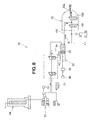
- a painting apparatus 200 shown in FIG. 9 comprises a manipulator 201 of a painting robot; a painting gun 202 mounted on a distal end of the manipulator 201; a colour changing valve unit 204 and a paint cartridge 206 mounted on the manipulator 201; and a paint feed device 208 connected to the colour changing valve unit 204 via a plurality of paint feed tubes 207.
- Reference numeral 209 denotes a first arm of the manipulator 201
- reference numeral 210 denotes a second arm of the manipulator 201.
- the colour changing valve unit 204 and the paint cartridge 206 are mounted on the second arm 210.
- the colour changing valve unit 204 or the paint cartridge 206 are positioned a large distance away from the painting gun 202, then when air inside a paint feed channel between the colour changing valve unit 204 (or the paint cartridge 206) and the painting gun 202 is expelled by filling the paint feed channel with paint from the colour changing valve unit 204 or the paint cartridge 206, the speed at which the paint feed channel is filled will vary dramatically depending on the viscosity of the paint and the ambient temperature. As a result, when the filling speed increases, the amount of discarded paint increases, and the amount of paint required for painting may occasionally be insufficient.
- the colour changing valve unit 204 and the paint cartridge 206 are attached to the manipulator 201, the moment of inertia of the manipulator 201 is increased, and movements such as quick swiveling become difficult. Moreover, the power for operating the manipulator 201 also increases. Furthermore, the size of the moving part increases, which may make painting tasks harder to perform in a cramped place.
- an electrostatic painting method in which an electrically conductive paint is supplied from a plurality of paint feed sections to,a colour changing valve mechanism, a paint feed channel and a painting gun, a method for continuing the electrostatic painting with the electrically conductive paint changed to a separate electrically conductive paint of different colour, comprising the steps of: switching a paint valve connected to the colour changing valve mechanism such that a first pathway of the paint valve is placed in communication with a paint cartridge that is connected to the paint valve, and a second pathway of the paint valve is placed in communication with a discharging channel of a fluid pathway connected to the paint valve, the fluid pathway being shorter than the paint feed channel; discharging the electrically conductive paint from the paint cartridge into the discharging channel of the fluid pathway; measuring a rate at which the electrically conductive paint flows into the discharging channel; switching the paint valve so that the paint cartridge communicates with the paint feed channel via a third pathway of the paint valve; and filling the paint feed channel with
- the quantity of electrically conductive paint required to fill the paint feed channel can be determined very accurately based on a highly accurate paint flow rate measurement result, allowing the quantity of the electrically conductive paint used to fill the paint feed channel to be maintained at a constant level.
- the quantity of the electrically conductive paint to be used to fill the paint feed channel with a long pathway can be estimated with a high degree of accuracy based on the flow rate measurement result, allowing the quantity of electrically conductive paint used to fill the paint feed channel to be maintained at a constant level.
- an electrostatic painting apparatus comprising: a paint feed channel for supplying an electrically conductive paint from a plurality of paint feed sections to a painting gun; a colour changing valve mechanism for switching the colour of the electrically conductive paint, the colour changing valve mechanism being provided to the paint feed channel so as to connect to the paint feed sections; a reservoir, provided to the paint feed channel closer to the painting gun than the colour changing valve mechanism, for temporarily storing the electrically conductive paint and propelling the stored electrically conductive paint towards the painting gun; an insulating section, provided to the paint feed channel, for electrically insulating the reservoir from the paint feed sections; and a fluid pathway provided to the colour changing valve mechanism so as to face the paint feed sections, wherein the fluid pathway comprises: a paint valve connected to the colour changing valve mechanism; a paint cartridge connected to the paint valve; a discharging channel capable of discharging the electrically conductive paint from the paint cartridge; and a flow rate measurement device for measuring the volume of flow of the electrically
- the quantity of electrically conductive paint to fill the paint feed channel can be determined very accurately based on a highly accurate paint flow rate measurement result, allowing the quantity of the electrically conductive paint used to fill the paint feed channel to be maintained at a constant level.
- a flow rate measuring device to measure the volume of the electrically conductive paint that flows through a fluid pathway having a short length makes it possible to minimize the extent to which the speed at which the fluid pathway is filled will be affected by the viscosity of the electrically conductive paint and the ambient temperature, and improve the accuracy with which the volume in which the electrically conductive paint flows is measured. Therefore, when air is to be expelled during colour changing the quantity of the electrically conductive paint to be used to fill the paint feed channel with a long pathway can be estimated with a high degree of accuracy based on the flow rate measurement result, allowing the quantity of electrically conductive paint used to fill the paint feed channel to be maintained at a constant level.
- the fluid pathway further comprises a stopping valve provided between the flow rate measuring device and the discharging channel. Accordingly, the stopping valve can prevent the paint from being discharged through the discharging channel, even when the paint leaks from the paint valve.
- the painting gun is held by a painting robot, wherein a paint cartridge installation section is provided to a base that is provided to the painting robot, and the paint cartridge is detachably installed in the paint cartridge installation section.
- a paint cartridge installation section is provided to a base that is provided to the painting robot, and the paint cartridge is detachably installed in the paint cartridge installation section.
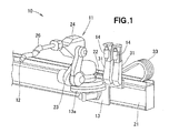
- an electrostatic painting apparatus 10 comprises a painting robot 11, which is slideably mounted on a support rail 21.
- the painting robot 11 comprises a base 31 mounted slideably on the support rail 21; a rotating section 22 rotatably mounted on a table 13a provided to the base 13; a first arm 23 swingably mounted on the rotating section 22; a head 24 swingably mounted on a distal end of the first arm 23; a second arm 26 mounted on a front end of the head 24; and a painting gun 12 mounted on a distal end section of the second arm 26.
- a plurality of paint cartridges 14 are detachably installed in a cartridge installation section 31, which is itself mounted on the base 13, and are connected to a colour changing valve mechanism 51 ( FIG. 2 ) provided to the painting robot 11, via a paint valve 63 ( FIG. 2 ).
- a top section of the support rail 21 supports a tube bundle 33 that comprises a plurality of paint feed tubes, each of whose ends being connected to a paint feed section 16 ( FIG. 2 ).
- the other end of the tube bundle 33 is connected to the colour changing valve mechanism 51 of the painting robot 11.
- the paint cartridge installation section 31 is provided to the base 13 of the painting robot 11, and the paint cartridge 14 is detachably installed in the paint cartridge installation section 31.
- the paint cartridge 14 is not provided to a moving part such as the head 24 or the arms 23, 26 of the painting robot 11, the moment of inertia of the moving part of the painting robot 11 is reduced, the accuracy with which the painting gun 12 is positioned is increased, the painting gun can be moved swiftly and precisely, and the amount of power required can be reduced. It is also possible to reduce the size of the moving part of the painting robot 11, allowing the painting task to be readily performed without obstruction, even when a cramped place such as an interior of an automotive vehicle is being painted.
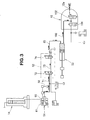
- the electrostatic painting apparatus 10 comprises: the colour changing valve mechanism 51, which is connected to a plurality of paint feed sections 16 supplying a plurality of electrically conductive paints of different colour, and used for switching supply of the electrically conductive paint; a block valve mechanism 52 for electrically insulating the colour changing valve mechanism 51 in the direction of the painting gun 12; a storage tank 53 for temporarily storing the electrically conductive paint, the storage tank 53 being connected to the block valve mechanism 52; the painting gun 12 for spraying the electrically conductive paint onto an automotive vehicle or other object to be painted; a fluid pathway 122 connected to the colour changing valve mechanism 51; and the paint cartridge 14 which is connected to the fluid pathway 122.
- the colour changing valve mechanism 51 comprises a first cleaning valve 61 for controlling the supply of drying air A, water W, and a cleaning liquid S; and a plurality of paint valves 63, 64 for controlling the supply of electrically conductive paint from a plurality of paint feed sections 16 that supply electrically conductive paints of different colour.
- the block valve mechanism 52 comprises a first switching valve 72 connected to the colour changing valve mechanism 51 via a feed channel 71 and a second switching valve 74 connected to the first switching valve 72 via a feed channel 73 that is an electrically insulated duct channel made of a plastic material.
- a first discharging channel 76 is connected to the feed channel 71 via a first dump valve 77.
- a second cleaning valve 78 is connected to the first switching valve 72 via a feed channel 81 and controls the supply of air A, water W and cleaning liquid S.
- a second discharging channel 82 is connected to a second switching valve 74 via a one-way valve 83.
- the first switching valve 72 switches between input from the direction of the colour changing valve mechanism 51 and input from the direction of the second cleaning valve 78.
- the second switching valve 74 switches the connection of the feed channel 73 between the direction of a feed channel 85 and the second discharging channel 82.
- the storage tank 53 comprises a cylinder 91, a piston 92 movably disposed within the cylinder 91, a rod 93 mounted to the piston 92, a cylinder chamber 94 described by the cylinder 91 and the piston 92, and an inlet 96 and an outlet 97 provided to an end section of the cylinder 91 and in communication with the cylinder chamber 94.
- a rod 93 is connected to a servo motor 98 via ball screw means 99. Driving the servo motor 98 causes the rod 93 and the piston 92 to move in the direction of the cylinder axis (the direction of arrow A), via the ball screw means 99.
- the painting gun 12 has a trigger valve 102, a second dump valve 101 connected to the outlet 97 of the storage tank 53 via a delivery channel 100, and an ejection hole 12a that is an end section of the delivery channel 100; and is connected to high-voltage-impressing means (not shown).
- the trigger valve 102 controls the ejection of electrically conductive paint from the painting gun 12.
- the second dump valve 101 is connected to a third discharging channel 104 for discharging waste fluid from the delivery channel 100, the waste fluid being generated during cleaning and including electrically conductive paint and cleaning liquid.
- the third discharging channel 104 is connected, via a one-way valve 107, to a third cleaning valve 106 that controls the supply of air A, water W, and cleaning liquid S.
- the feed channels 71, 73, 85, storage tank 53 and the delivery channel 100 constitute a main feed channel 108 that extends from the paint feed section 16 to the painting gun 12.
- the paint cartridge 14 has a cylinder hole 111; a free piston 112 movably disposed within the cylinder hole 111; a fluid channel 116 that connects a fluid chamber 113 to a source of supply of fluid such as water or air (not shown), the interior of the cylinder hole 111 being divided into the fluid chamber 113 and a paint chamber 114 by the free piston 112; and a paint channel 117 that connects the paint chamber 114 within the cylinder hole 111 to the cartridge installation section 31.
- the cartridge installation section 31 and the fluid pathway 122 i.e., a paint valve 55, described later
- the paint cartridge 14 is filled with enough electrically conductive paint for two to six vehicles.
- the paint is applied by the painting robot 11 (shown in FIG. 1 ) to an interior of an engine compartment, where an engine hood and a fender section of a body of a passenger vehicle (not shown) or a motorcycle (not shown) meet, a body section where a door and the body meet, or similar sections, the parts such as the engine hood or the door being in an attached state.
- the paint cartridge 14 is installed in a side opposite the side of the painting gun 12 as viewed from the colour changing valve mechanism 51 provided to the painting robot 11. As a result, the moment of inertia of the moving part of the painting robot 11 is reduced.
- the amount of electrically conductive paint inside the paint cartridge 14 decreases as more vehicles are painted. Therefore, in contrast to instances where the paint cartridge is installed in an arm or other moving part of the painting robot 11, in the present embodiment fluctuations in the moment of inertial of the moving part of the painting robot 11 are eliminated, the accuracy with which the painting gun is positioned is increased, the painting gun can be moved swiftly and precisely, and the amount of power required can be reduced.
- the present embodiment is suitable for painting cramped locations such as the interior of the engine compartment or a body section where a door and body meet, such as a pillar section, a door hinge section, or the like.
- the paint valve 55 connected to the colour changing valve mechanism 51, a phototube 56 connected to the paint valve 55, a stopping valve 57 connected to the phototube 56, and a discharge channel 58 connected to the stopping valve 57 are provided to the fluid pathway 122.
- the paint valve 55 has a pathway (first pathway) connected to the paint cartridge 14, another pathway (second pathway) connected to the discharge channel 58 of the fluid pathway 122, and another pathway (third pathway) connected to the colour changing valve mechanism 51.
- the paint valve 55 can switch between a flow channel through which the electrically conductive paint from the paint cartridge 14 flows to the discharge channel 58, and a flow channel through which the electrically conductive paint from the paint cartridge 14 flows to the colour changing valve mechanism 51.
- the phototube 56 measures the amount (and rate) at which the electrically conductive paint fills the fluid pathway 122.
- the flow of the electrically conductive paint through the fluid pathway 122 is less susceptible to the effect of the viscosity of the electrically conductive paint or the ambient temperature than when the electrically conductive paint is made to flow through, for example, the feed channel 71 of the paint feed channel; and the accuracy with which the flow rate of the electrically conductive paint is measured by the phototube 56 is improved.
- the stopping valve 57 prevents the electrically conductive paint from being discharged to the discharge channel 58 even if the electrically conductive paint leaks out in the direction of the discharge channel 58 when the flow channel is being switched by the paint valve 55 to the pathway from the paint cartridge 14 to the colour changing valve mechanism 51.
- the feed channel 118 is included in the fluid pathway 122.
- the time taken for filling varies significantly depending on the viscosity of the paint or the ambient temperature, because there is a great distance between the paint cartridge 14 and, for example, the first switching valve 72 of the paint feed channel. Therefore, by first making the electrically conductive paint flow from the paint cartridge 14 to the discharge channel 58, and using the phototube 56 to measure the flow (rate) of the electrically conductive paint, the time required to fill the paint feed channel with the electrically conductive paint can be determined with a high degree of accuracy based on the result of the flow rate measurement.
- FIG. 3 shows the paint feed channel of the electrostatic painting apparatus being cleaned.
- the first cleaning valve 61 of the colour changing valve mechanism 51 is opened and cleaning liquid S is directed into the paint feed channel in the direction indicated by the dotted arrow. This is performed in a state wherein the first and second switching valves 72, 74 of the block valve mechanism 52 are opened, the pathway at the paint valve 55 is switched to the direction of the discharge channel 58, the pathway between the paint cartridge 14 and the colour changing valve mechanism 51 is blocked, the second dump valve 101 is closed, and the trigger valve 102 is opened.
- the interior of the colour changing valve mechanism 51, the feed channels 71, 73, 85, the interior of the storage tank 53, the delivery channel 100, and the interior of the painting gun 12 will be cleaned by the cleaning liquid S.
- the cleaning liquid S is discharged from the ejection hole 12a.
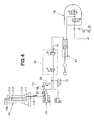
- FIG. 4 shows a state in which the volume of flow of an electrically conductive paint is measured, conducted before the air is expelled from the paint feed channel.
- Water or air is supplied to the fluid chamber 113 of the paint cartridge 14 via the fluid channel 116; the free piston 112 is moved so as to compress the electrically conductive paint inside the paint chamber 114; and the electrically conductive paint is channeled to a flow channel 121 via the paint channel 117, the feed channel 118, and the paint valve 55.
- the flow rate of the electrically conductive paint i.e., the speed at which the flow channel 121 is being filled, is measured by the phototube 56, and the electrically conductive paint flows to the direction of the discharge channel 58.
- the result of the flow rate measurement performed using the phototube 56 is recorded in a memory section (not shown), together with the viscosity of the electrically conductive paint and the ambient temperature.
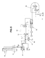
- FIG. 5 shows a state in which air is expelled from the paint feed channel.
- the electrically conductive paint is supplied from the paint cartridge 14 to the feed channel 71 via the colour changing valve mechanism 51, and air is expelled from the colour changing valve mechanism 51 and the feed channel 71.
- the first switching valve 72 is closed, the first dump valve 77 is opened, and the supply of paint is terminated after a specified time once paint starts to be supplied from the paint cartridge 14.
- the specified time is determined based on the measurement of the flow rate of the electrically conductive paint as shown on FIG. 4 and the length of the paint feed channel.
- the colour changing valve mechanism 51 and the feed channel 71 are filled with the electrically conductive paint.
- the introduced paint is discharged from the first discharging channel 76 in an amount equating to the difference with respect to the amount obtained based on the result of the measurement of the flow rate of the paint.
- the electrically conductive paint is thus supplied to the paint feed channel based on the results of the measurement of the flow rate of the electrically conductive paint; therefore, the paint feed channel can be filled very accurately with an amount of the electrically conductive paint, and the electrically conductive paint inside the paint cartridge 14 does not have to be wasted.
- FIG. 6 shows a state in which a storage tank 53 is filled with the paint.
- FIG. 7 shows a state in which the interior of a block valve mechanism 52 is cleaned and dried in order to insulate the interior of the block valve mechanism 52.
- the pathways of the first and second switching valves 72, 74 of the block valve mechanism 52 are switched, the second cleaning valve 78 is opened, the cleaning liquid is supplied from the second cleaning valve 78 to the feed channel 73 as indicated by an arrow C, and the feed channel 73 is cleaned.
- the resulting waste liquid is discharged from the second discharging channel 82.
- the feed channel 73 is then dried by supplying air from the second cleaning valve 78 to the feed channel 73 as indicated by an arrow D.
- the switching valves 72, 74 are electrically insulated against each other.
- FIG. 8 shows a state in which the electrically conductive paint inside the storage tank is applied.
- the trigger valve 102 is opened, the servo motor 98 is driven, and the piston 92 is moved in a direction indicated by an arrow A2, whereby the electrically conductive paint is pushed from the cylinder chamber 94 into the delivery channel 100.
- the electrically conductive paint is thereby caused to pass through the trigger valve 102 as indicated by arrow B, and is ejected from the ejection hole 12a.
- a high voltage is applied to the electrically conductive paint, and an object to be painted (not shown) is electrostatically painted.
- using the phototube 56 to measure the flow rate of the electrically conductive paint within the fluid pathway 122, whose pathway is short, makes it possible to minimize the extent to which the speed at which the fluid pathway 122 is filled will be affected by the viscosity of the electrically conductive paint and the ambient temperature, and improve the accuracy with which the volume in which the electrically conductive paint flows is measured.
- the quantity of the electrically conductive paint to be used to fill the main paint feed channel 108 with a long pathway can be estimated with a high degree of accuracy based on the flow rate measurement result, allowing the quantity of electrically conductive paint used to fill the main paint feed channel 108 to be maintained at a constant level.
- the stopping valve 57 for stopping the flow of electrically conductive paint is provided between the phototube 56 and the discharge channel 58; therefore, the stopping valve 57 can prevent the paint from being discharged through the discharging channel 58, even when the paint leaks from the paint valve 55.
Landscapes
- Electrostatic Spraying Apparatus (AREA)
- Spray Control Apparatus (AREA)
- Application Of Or Painting With Fluid Materials (AREA)
- Liquid Crystal (AREA)
Applications Claiming Priority (1)
| Application Number | Priority Date | Filing Date | Title |
|---|---|---|---|
| JP2008185411A JP5054629B2 (ja) | 2008-07-16 | 2008-07-16 | 静電塗装方法及び静電塗装装置 |
Publications (2)
| Publication Number | Publication Date |
|---|---|
| EP2145690A1 true EP2145690A1 (de) | 2010-01-20 |
| EP2145690B1 EP2145690B1 (de) | 2010-09-29 |
Family
ID=41066313
Family Applications (1)
| Application Number | Title | Priority Date | Filing Date |
|---|---|---|---|
| EP09251803A Not-in-force EP2145690B1 (de) | 2008-07-16 | 2009-07-15 | Elektrostatisches Lackierverfahren und Vorrichtung |
Country Status (6)
| Country | Link |
|---|---|
| US (1) | US8146840B2 (de) |
| EP (1) | EP2145690B1 (de) |
| JP (1) | JP5054629B2 (de) |
| CN (1) | CN101628280B (de) |
| AT (1) | ATE482768T1 (de) |
| DE (1) | DE602009000241D1 (de) |
Families Citing this family (15)
| Publication number | Priority date | Publication date | Assignee | Title |
|---|---|---|---|---|
| US20100129641A1 (en) * | 2008-11-25 | 2010-05-27 | Lopez Leonardo C | Polymer carbon composites |
| US20100127434A1 (en) * | 2008-11-25 | 2010-05-27 | Rene Broos | Extruding organic polymers |
| US8440297B2 (en) * | 2008-11-25 | 2013-05-14 | Dow Global Technologies Llc | Polymer organoclay composites |
| JP4812871B2 (ja) * | 2009-10-21 | 2011-11-09 | トヨタ自動車株式会社 | 塗料充填装置 |
| JP4850944B2 (ja) | 2009-10-21 | 2012-01-11 | トヨタ自動車株式会社 | 塗料供給方法 |
| US10149390B2 (en) | 2012-08-27 | 2018-12-04 | Mycronic AB | Maskless writing of a workpiece using a plurality of exposures having different focal planes using multiple DMDs |
| JP5936977B2 (ja) * | 2012-10-01 | 2016-06-22 | 本田技研工業株式会社 | 静電塗装装置 |
| JP5616940B2 (ja) * | 2012-10-12 | 2014-10-29 | 本田技研工業株式会社 | 静電塗装装置 |
| CN107787254B (zh) | 2015-06-11 | 2021-01-15 | 诺信公司 | 筒式流体分配设备 |
| CN105797886A (zh) * | 2016-05-24 | 2016-07-27 | 四川晟翔晟智能科技有限公司 | 涂料静电喷涂系统 |
| US10675653B2 (en) * | 2017-02-07 | 2020-06-09 | Nordson Corporation | Motorized cartridge type fluid dispensing apparatus and system |
| JP6823723B2 (ja) | 2017-07-18 | 2021-02-03 | エービービー シュヴァイツ エージーABB Schweiz AG | 塗装装置 |
| JP6948487B1 (ja) * | 2021-06-23 | 2021-10-13 | アーベーベー・シュバイツ・アーゲーABB Schweiz AG | 静電塗装装置 |
| WO2023194740A1 (en) * | 2022-04-06 | 2023-10-12 | Micropply Limited | A detachable ground deposition accessory |
| CN114985209B (zh) * | 2022-06-28 | 2023-03-21 | 广汽本田汽车有限公司 | 一种用于后车门铰链侧的涂胶方法及涂胶系统 |
Citations (3)
| Publication number | Priority date | Publication date | Assignee | Title |
|---|---|---|---|---|
| US5288525A (en) * | 1992-03-24 | 1994-02-22 | Binks Manufacturing Company | Method of and system for delivering conductive coating material to electrostatic spraying apparatus |
| JPH11267560A (ja) | 1998-03-20 | 1999-10-05 | Tokico Ltd | 塗装用ロボット |
| EP1097751A2 (de) * | 1999-11-02 | 2001-05-09 | Illinois Tool Works Inc. | Überwachungssystem für eine Vorrichtung zur Spannungssperrung |
Family Cites Families (6)
| Publication number | Priority date | Publication date | Assignee | Title |
|---|---|---|---|---|
| DE3440381A1 (de) * | 1984-11-05 | 1986-05-07 | Ransburg Gmbh, 6056 Heusenstamm | Verfahren und vorrichtung zum automatischen elektrostatischen spruehbeschichten |
| DE3725172A1 (de) * | 1987-05-27 | 1989-02-09 | Behr Industrieanlagen | Verfahren und anlage zum elektrostatischen beschichten mit leitfaehigem material |
| US4932589A (en) * | 1988-09-30 | 1990-06-12 | Binks Manufacturing Company | Method of and apparatus for electrical isolation of electrostatic sprayers |
| US5102045A (en) * | 1991-02-26 | 1992-04-07 | Binks Manufacturing Company | Apparatus for and method of metering coating material in an electrostatic spraying system |
| US5328093A (en) * | 1993-07-28 | 1994-07-12 | Graco Inc. | Water-based plural component spray painting system |
| CN100496761C (zh) * | 2002-10-23 | 2009-06-10 | 美国发那科机器人有限公司 | 机器人喷涂装置及其操作方法 |
-
2008
- 2008-07-16 JP JP2008185411A patent/JP5054629B2/ja not_active Expired - Fee Related
-
2009
- 2009-07-15 US US12/503,378 patent/US8146840B2/en not_active Expired - Fee Related
- 2009-07-15 DE DE602009000241T patent/DE602009000241D1/de active Active
- 2009-07-15 CN CN2009101517832A patent/CN101628280B/zh not_active Expired - Fee Related
- 2009-07-15 EP EP09251803A patent/EP2145690B1/de not_active Not-in-force
- 2009-07-15 AT AT09251803T patent/ATE482768T1/de not_active IP Right Cessation
Patent Citations (3)
| Publication number | Priority date | Publication date | Assignee | Title |
|---|---|---|---|---|
| US5288525A (en) * | 1992-03-24 | 1994-02-22 | Binks Manufacturing Company | Method of and system for delivering conductive coating material to electrostatic spraying apparatus |
| JPH11267560A (ja) | 1998-03-20 | 1999-10-05 | Tokico Ltd | 塗装用ロボット |
| EP1097751A2 (de) * | 1999-11-02 | 2001-05-09 | Illinois Tool Works Inc. | Überwachungssystem für eine Vorrichtung zur Spannungssperrung |
Also Published As
| Publication number | Publication date |
|---|---|
| US20100012743A1 (en) | 2010-01-21 |
| EP2145690B1 (de) | 2010-09-29 |
| JP5054629B2 (ja) | 2012-10-24 |
| DE602009000241D1 (de) | 2010-11-11 |
| JP2010022912A (ja) | 2010-02-04 |
| CN101628280A (zh) | 2010-01-20 |
| CN101628280B (zh) | 2012-10-17 |
| ATE482768T1 (de) | 2010-10-15 |
| US8146840B2 (en) | 2012-04-03 |
Similar Documents
| Publication | Publication Date | Title |
|---|---|---|
| EP2145690B1 (de) | Elektrostatisches Lackierverfahren und Vorrichtung | |
| US11154892B2 (en) | Coating device for applying coating agent in a controlled manner | |
| EP2416890B2 (de) | Verbessertes robotisches malsystem und -verfahren | |
| US8051796B2 (en) | Robotic apparatus and method for painting | |
| JP6803312B2 (ja) | 粘性材料吐出装置 | |
| JP4755605B2 (ja) | 静電塗装装置 | |
| US20070188531A1 (en) | Method of adjusting a liquid droplet, method of discharging the liquid droplet and apparatus therefor | |
| US12048940B2 (en) | Electrostatic coating apparatus | |
| CN101547747B (zh) | 静电涂装方法及其装置 | |
| CN103301969B (zh) | 静电喷涂系统的中间蓄留装置、其清洗方法及喷涂方法 | |
| JP2003126750A (ja) | 液材の吐出方法およびその装置 | |
| CN118159365A (zh) | 用于供应涂覆介质的供应设备、涂覆介质装置、涂覆介质供应系统和方法 | |
| CN100400175C (zh) | 静电喷涂方法和静电喷涂装置 | |
| JP5080786B2 (ja) | 塗装システム | |
| JP4736063B2 (ja) | 流路切替え装置 | |
| KR20030018926A (ko) | 차량 도포용 도료 토출 장치의 제어 방법 | |
| JP4825554B2 (ja) | 塗料の定量供給制御装置および方法 | |
| JP2021094545A (ja) | 塗料供給用シリンジポンプ | |
| JP2004275977A (ja) | 静電塗装方法および静電塗装装置の中間貯留機構 | |
| JP5843747B2 (ja) | 塗装装置及び塗装方法 | |
| JP4282057B2 (ja) | 液材の吐出装置 | |
| JP2005185908A (ja) | 静電塗装装置 | |
| JPWO2023135797A5 (de) | ||
| JPS63175663A (ja) | 塗料吐出制御装置 |
Legal Events
| Date | Code | Title | Description |
|---|---|---|---|
| PUAI | Public reference made under article 153(3) epc to a published international application that has entered the european phase |
Free format text: ORIGINAL CODE: 0009012 |
|
| AK | Designated contracting states |
Kind code of ref document: A1 Designated state(s): AT BE BG CH CY CZ DE DK EE ES FI FR GB GR HR HU IE IS IT LI LT LU LV MC MK MT NL NO PL PT RO SE SI SK SM TR |
|
| AX | Request for extension of the european patent |
Extension state: AL BA RS |
|
| 17P | Request for examination filed |
Effective date: 20100107 |
|
| GRAP | Despatch of communication of intention to grant a patent |
Free format text: ORIGINAL CODE: EPIDOSNIGR1 |
|
| GRAS | Grant fee paid |
Free format text: ORIGINAL CODE: EPIDOSNIGR3 |
|
| GRAA | (expected) grant |
Free format text: ORIGINAL CODE: 0009210 |
|
| AK | Designated contracting states |
Kind code of ref document: B1 Designated state(s): AT BE BG CH CY CZ DE DK EE ES FI FR GB GR HR HU IE IS IT LI LT LU LV MC MK MT NL NO PL PT RO SE SI SK SM TR |
|
| REG | Reference to a national code |
Ref country code: GB Ref legal event code: FG4D |
|
| REG | Reference to a national code |
Ref country code: CH Ref legal event code: EP |
|
| REG | Reference to a national code |
Ref country code: IE Ref legal event code: FG4D |
|
| REF | Corresponds to: |
Ref document number: 602009000241 Country of ref document: DE Date of ref document: 20101111 Kind code of ref document: P |
|
| PG25 | Lapsed in a contracting state [announced via postgrant information from national office to epo] |
Ref country code: LT Free format text: LAPSE BECAUSE OF FAILURE TO SUBMIT A TRANSLATION OF THE DESCRIPTION OR TO PAY THE FEE WITHIN THE PRESCRIBED TIME-LIMIT Effective date: 20100929 Ref country code: AT Free format text: LAPSE BECAUSE OF FAILURE TO SUBMIT A TRANSLATION OF THE DESCRIPTION OR TO PAY THE FEE WITHIN THE PRESCRIBED TIME-LIMIT Effective date: 20100929 Ref country code: FI Free format text: LAPSE BECAUSE OF FAILURE TO SUBMIT A TRANSLATION OF THE DESCRIPTION OR TO PAY THE FEE WITHIN THE PRESCRIBED TIME-LIMIT Effective date: 20100929 Ref country code: NO Free format text: LAPSE BECAUSE OF FAILURE TO SUBMIT A TRANSLATION OF THE DESCRIPTION OR TO PAY THE FEE WITHIN THE PRESCRIBED TIME-LIMIT Effective date: 20101229 |
|
| REG | Reference to a national code |
Ref country code: NL Ref legal event code: VDEP Effective date: 20100929 |
|
| LTIE | Lt: invalidation of european patent or patent extension |
Effective date: 20100929 |
|
| PG25 | Lapsed in a contracting state [announced via postgrant information from national office to epo] |
Ref country code: HR Free format text: LAPSE BECAUSE OF FAILURE TO SUBMIT A TRANSLATION OF THE DESCRIPTION OR TO PAY THE FEE WITHIN THE PRESCRIBED TIME-LIMIT Effective date: 20100929 Ref country code: SI Free format text: LAPSE BECAUSE OF FAILURE TO SUBMIT A TRANSLATION OF THE DESCRIPTION OR TO PAY THE FEE WITHIN THE PRESCRIBED TIME-LIMIT Effective date: 20100929 |
|
| PG25 | Lapsed in a contracting state [announced via postgrant information from national office to epo] |
Ref country code: SE Free format text: LAPSE BECAUSE OF FAILURE TO SUBMIT A TRANSLATION OF THE DESCRIPTION OR TO PAY THE FEE WITHIN THE PRESCRIBED TIME-LIMIT Effective date: 20100929 Ref country code: LV Free format text: LAPSE BECAUSE OF FAILURE TO SUBMIT A TRANSLATION OF THE DESCRIPTION OR TO PAY THE FEE WITHIN THE PRESCRIBED TIME-LIMIT Effective date: 20100929 Ref country code: GR Free format text: LAPSE BECAUSE OF FAILURE TO SUBMIT A TRANSLATION OF THE DESCRIPTION OR TO PAY THE FEE WITHIN THE PRESCRIBED TIME-LIMIT Effective date: 20101230 |
|
| PG25 | Lapsed in a contracting state [announced via postgrant information from national office to epo] |
Ref country code: NL Free format text: LAPSE BECAUSE OF FAILURE TO SUBMIT A TRANSLATION OF THE DESCRIPTION OR TO PAY THE FEE WITHIN THE PRESCRIBED TIME-LIMIT Effective date: 20100929 Ref country code: SK Free format text: LAPSE BECAUSE OF FAILURE TO SUBMIT A TRANSLATION OF THE DESCRIPTION OR TO PAY THE FEE WITHIN THE PRESCRIBED TIME-LIMIT Effective date: 20100929 Ref country code: EE Free format text: LAPSE BECAUSE OF FAILURE TO SUBMIT A TRANSLATION OF THE DESCRIPTION OR TO PAY THE FEE WITHIN THE PRESCRIBED TIME-LIMIT Effective date: 20100929 Ref country code: PT Free format text: LAPSE BECAUSE OF FAILURE TO SUBMIT A TRANSLATION OF THE DESCRIPTION OR TO PAY THE FEE WITHIN THE PRESCRIBED TIME-LIMIT Effective date: 20110131 Ref country code: IS Free format text: LAPSE BECAUSE OF FAILURE TO SUBMIT A TRANSLATION OF THE DESCRIPTION OR TO PAY THE FEE WITHIN THE PRESCRIBED TIME-LIMIT Effective date: 20110129 Ref country code: IT Free format text: LAPSE BECAUSE OF FAILURE TO SUBMIT A TRANSLATION OF THE DESCRIPTION OR TO PAY THE FEE WITHIN THE PRESCRIBED TIME-LIMIT Effective date: 20100929 Ref country code: CZ Free format text: LAPSE BECAUSE OF FAILURE TO SUBMIT A TRANSLATION OF THE DESCRIPTION OR TO PAY THE FEE WITHIN THE PRESCRIBED TIME-LIMIT Effective date: 20100929 Ref country code: RO Free format text: LAPSE BECAUSE OF FAILURE TO SUBMIT A TRANSLATION OF THE DESCRIPTION OR TO PAY THE FEE WITHIN THE PRESCRIBED TIME-LIMIT Effective date: 20100929 |
|
| PG25 | Lapsed in a contracting state [announced via postgrant information from national office to epo] |
Ref country code: BE Free format text: LAPSE BECAUSE OF FAILURE TO SUBMIT A TRANSLATION OF THE DESCRIPTION OR TO PAY THE FEE WITHIN THE PRESCRIBED TIME-LIMIT Effective date: 20100929 |
|
| PG25 | Lapsed in a contracting state [announced via postgrant information from national office to epo] |
Ref country code: ES Free format text: LAPSE BECAUSE OF FAILURE TO SUBMIT A TRANSLATION OF THE DESCRIPTION OR TO PAY THE FEE WITHIN THE PRESCRIBED TIME-LIMIT Effective date: 20110109 |
|
| PLBE | No opposition filed within time limit |
Free format text: ORIGINAL CODE: 0009261 |
|
| STAA | Information on the status of an ep patent application or granted ep patent |
Free format text: STATUS: NO OPPOSITION FILED WITHIN TIME LIMIT |
|
| PG25 | Lapsed in a contracting state [announced via postgrant information from national office to epo] |
Ref country code: PL Free format text: LAPSE BECAUSE OF FAILURE TO SUBMIT A TRANSLATION OF THE DESCRIPTION OR TO PAY THE FEE WITHIN THE PRESCRIBED TIME-LIMIT Effective date: 20100929 Ref country code: DK Free format text: LAPSE BECAUSE OF FAILURE TO SUBMIT A TRANSLATION OF THE DESCRIPTION OR TO PAY THE FEE WITHIN THE PRESCRIBED TIME-LIMIT Effective date: 20100929 |
|
| REG | Reference to a national code |
Ref country code: DE Ref legal event code: R097 Ref document number: 602009000241 Country of ref document: DE Effective date: 20110630 |
|
| PG25 | Lapsed in a contracting state [announced via postgrant information from national office to epo] |
Ref country code: MT Free format text: LAPSE BECAUSE OF FAILURE TO SUBMIT A TRANSLATION OF THE DESCRIPTION OR TO PAY THE FEE WITHIN THE PRESCRIBED TIME-LIMIT Effective date: 20100929 |
|
| PG25 | Lapsed in a contracting state [announced via postgrant information from national office to epo] |
Ref country code: MC Free format text: LAPSE BECAUSE OF NON-PAYMENT OF DUE FEES Effective date: 20110731 |
|
| REG | Reference to a national code |
Ref country code: IE Ref legal event code: MM4A |
|
| PG25 | Lapsed in a contracting state [announced via postgrant information from national office to epo] |
Ref country code: IE Free format text: LAPSE BECAUSE OF NON-PAYMENT OF DUE FEES Effective date: 20110715 |
|
| PG25 | Lapsed in a contracting state [announced via postgrant information from national office to epo] |
Ref country code: MK Free format text: LAPSE BECAUSE OF FAILURE TO SUBMIT A TRANSLATION OF THE DESCRIPTION OR TO PAY THE FEE WITHIN THE PRESCRIBED TIME-LIMIT Effective date: 20100929 |
|
| PG25 | Lapsed in a contracting state [announced via postgrant information from national office to epo] |
Ref country code: SM Free format text: LAPSE BECAUSE OF FAILURE TO SUBMIT A TRANSLATION OF THE DESCRIPTION OR TO PAY THE FEE WITHIN THE PRESCRIBED TIME-LIMIT Effective date: 20100929 |
|
| PG25 | Lapsed in a contracting state [announced via postgrant information from national office to epo] |
Ref country code: LU Free format text: LAPSE BECAUSE OF NON-PAYMENT OF DUE FEES Effective date: 20110715 Ref country code: CY Free format text: LAPSE BECAUSE OF EXPIRATION OF PROTECTION Effective date: 20100929 |
|
| PG25 | Lapsed in a contracting state [announced via postgrant information from national office to epo] |
Ref country code: TR Free format text: LAPSE BECAUSE OF FAILURE TO SUBMIT A TRANSLATION OF THE DESCRIPTION OR TO PAY THE FEE WITHIN THE PRESCRIBED TIME-LIMIT Effective date: 20100929 Ref country code: BG Free format text: LAPSE BECAUSE OF FAILURE TO SUBMIT A TRANSLATION OF THE DESCRIPTION OR TO PAY THE FEE WITHIN THE PRESCRIBED TIME-LIMIT Effective date: 20101229 |
|
| PG25 | Lapsed in a contracting state [announced via postgrant information from national office to epo] |
Ref country code: HU Free format text: LAPSE BECAUSE OF FAILURE TO SUBMIT A TRANSLATION OF THE DESCRIPTION OR TO PAY THE FEE WITHIN THE PRESCRIBED TIME-LIMIT Effective date: 20100929 |
|
| PGFP | Annual fee paid to national office [announced via postgrant information from national office to epo] |
Ref country code: DE Payment date: 20130711 Year of fee payment: 5 |
|
| PGFP | Annual fee paid to national office [announced via postgrant information from national office to epo] |
Ref country code: FR Payment date: 20130724 Year of fee payment: 5 |
|
| REG | Reference to a national code |
Ref country code: CH Ref legal event code: PL |
|
| PG25 | Lapsed in a contracting state [announced via postgrant information from national office to epo] |
Ref country code: LI Free format text: LAPSE BECAUSE OF NON-PAYMENT OF DUE FEES Effective date: 20130731 Ref country code: CH Free format text: LAPSE BECAUSE OF NON-PAYMENT OF DUE FEES Effective date: 20130731 |
|
| PGFP | Annual fee paid to national office [announced via postgrant information from national office to epo] |
Ref country code: GB Payment date: 20140709 Year of fee payment: 6 |
|
| REG | Reference to a national code |
Ref country code: DE Ref legal event code: R119 Ref document number: 602009000241 Country of ref document: DE |
|
| REG | Reference to a national code |
Ref country code: FR Ref legal event code: ST Effective date: 20150331 |
|
| PG25 | Lapsed in a contracting state [announced via postgrant information from national office to epo] |
Ref country code: DE Free format text: LAPSE BECAUSE OF NON-PAYMENT OF DUE FEES Effective date: 20150203 |
|
| REG | Reference to a national code |
Ref country code: DE Ref legal event code: R119 Ref document number: 602009000241 Country of ref document: DE Effective date: 20150203 |
|
| PG25 | Lapsed in a contracting state [announced via postgrant information from national office to epo] |
Ref country code: FR Free format text: LAPSE BECAUSE OF NON-PAYMENT OF DUE FEES Effective date: 20140731 |
|
| GBPC | Gb: european patent ceased through non-payment of renewal fee |
Effective date: 20150715 |
|
| PG25 | Lapsed in a contracting state [announced via postgrant information from national office to epo] |
Ref country code: GB Free format text: LAPSE BECAUSE OF NON-PAYMENT OF DUE FEES Effective date: 20150715 |