EP2144574B1 - Hand-held device for dispensing a pasty filling material - Google Patents
Hand-held device for dispensing a pasty filling material Download PDFInfo
- Publication number
- EP2144574B1 EP2144574B1 EP08749398.7A EP08749398A EP2144574B1 EP 2144574 B1 EP2144574 B1 EP 2144574B1 EP 08749398 A EP08749398 A EP 08749398A EP 2144574 B1 EP2144574 B1 EP 2144574B1
- Authority
- EP
- European Patent Office
- Prior art keywords
- hand
- held device
- filling material
- dispensing
- filling
- Prior art date
- Legal status (The legal status is an assumption and is not a legal conclusion. Google has not performed a legal analysis and makes no representation as to the accuracy of the status listed.)
- Active
Links
Images


Classifications
-
- A—HUMAN NECESSITIES
- A61—MEDICAL OR VETERINARY SCIENCE; HYGIENE
- A61C—DENTISTRY; APPARATUS OR METHODS FOR ORAL OR DENTAL HYGIENE
- A61C19/00—Dental auxiliary appliances
- A61C19/003—Apparatus for curing resins by radiation
- A61C19/004—Hand-held apparatus, e.g. guns
-
- A—HUMAN NECESSITIES
- A61—MEDICAL OR VETERINARY SCIENCE; HYGIENE
- A61C—DENTISTRY; APPARATUS OR METHODS FOR ORAL OR DENTAL HYGIENE
- A61C1/00—Dental machines for boring or cutting ; General features of dental machines or apparatus, e.g. hand-piece design
- A61C1/02—Dental machines for boring or cutting ; General features of dental machines or apparatus, e.g. hand-piece design characterised by the drive of the dental tools
- A61C1/07—Dental machines for boring or cutting ; General features of dental machines or apparatus, e.g. hand-piece design characterised by the drive of the dental tools with vibratory drive, e.g. ultrasonic
-
- A—HUMAN NECESSITIES
- A61—MEDICAL OR VETERINARY SCIENCE; HYGIENE
- A61C—DENTISTRY; APPARATUS OR METHODS FOR ORAL OR DENTAL HYGIENE
- A61C5/00—Filling or capping teeth
- A61C5/60—Devices specially adapted for pressing or mixing capping or filling materials, e.g. amalgam presses
- A61C5/62—Applicators, e.g. syringes or guns
Description
Die vorliegende Erfindung betrifft ein Handgerät gemäß dem Oberbegriff des Anspruchs 1, welches insbesondere für dentale Zwecke vorgesehen ist und Mittel zur Abgabe eines pastösen Füllungsmaterials aufweist.The present invention relates to a hand-held device according to the preamble of
In der Medizintechnik ist es bekannt, Kavitäten in einem tierischen oder menschlichen Körperteil mit einem aushärtbaren Füllungsmaterial auszufüllen. Hierfür werden Füllungsmaterialien verwendet, welche in einem pastösen oder flüssigen Zustand in die Kavität eingebracht werden und anschließend aushärten bzw. ausgehärtet werden. Das Aushärten dieser Füllungsmaterialien kann dabei insbesondere durch Bestrahlung derselben mit Licht geeigneter Wellenlänge unterstützt werden.In medical technology, it is known to fill cavities in an animal or human body part with a curable filling material. For this purpose, filling materials are used, which are introduced in a pasty or liquid state into the cavity and then cured or cured. The curing of these filling materials can be assisted in particular by irradiating the same with light of suitable wavelength.
Ein zahnärztliches Handgerät, welches zur Abgabe einer pastösen Füllmasse ausgestaltet ist, ist bspw. aus der
Üblicherweise erfolgt der Prozess der Einbringung der lichthärtenden Füllungsmaterialien schichtweise, um die Kavität in optimaler Weise auszufüllen. Hierbei wird jeweils eine geringe Menge des Füllungsmaterials in die Kavität einbracht und anschließend ausgehärtet, was bspw. mit Hilfe einer Lichtpolymerisationslampe erfolgen kann, wie sie in den Veröffentlichungen
Ein zahnärztliches Handgerät, welches diese beiden Arbeitsschritte vereint ist beispielsweise in den Schriften
Die
Der vorliegenden Erfindung liegt die Aufgabe zugrunde, ausgehend von dem vorstehend beschriebenen Stand der Technik ein Handgerät, wie es bspw. aus der
Die Aufgabe wird durch ein Handgerät mit den Merkmalen des unabhängigen Anspruchs 1 gelöst. Vorteilhafte Weiterbildungen der Erfindung sind Gegenstand der abhängigen Ansprüche.The object is achieved by a hand-held device with the features of
Gemäß der vorliegenden Erfindung wird ein Handgerät, insbesondere für dentale Zwecke vorgeschlagen, welches zunächst Mittel zur Abgabe eines pastösen Füllungsmaterials aufweist. Erfindungsgemäß ist das Handgerät dadurch gekennzeichnet, dass zusätzlich Mittel zur Abgabe einer die Aushärtung das Füllungsmaterials bewirkenden Strahlung an dem Handgerät vorgesehen sind.According to the present invention, a hand-held device is proposed, in particular for dental purposes, which first comprises means for dispensing a pasty filling material. According to the invention, the hand-held device is characterized in that, in addition, means for dispensing a radiation causing the filling material to be provided on the hand-held device are provided.
Die erfindungsgemäße Lösung beruht also auf dem Gedanken, dass nunmehr ein Handgerät zur Verfügung gestellt wird, welches beide Zwecke - Abgabe des pastösen Füllungsmaterials und strahlungsinduzierte Aushärtung des Füllungsmaterials - erfüllt. Dies hat zur Folge, dass ein Zahnarzt bei dem Einbringen der Füllung in die Zahnkavität nicht dauerhaft zwischen zwei verschiedenen Geräten wechseln muss, sondern stattdessen über den gesamten Arbeitsvorgang hinweg ein einziges Gerät benutzen kann. Dies führt nicht nur zu einer Erleichterung der Durchführung der Prozedur, sondern auch zu einer nicht unbeträchtlichen Zeitersparnis. Ferner kann die Qualität des Arbeitsvorgangs verbessert werden, da es nicht mehr erforderlich ist, in wiederholtem Male ein Handgerät neu an dem zu behandelnden Zahn anzusetzen.The solution according to the invention is thus based on the idea that now a hand-held device is provided which fulfills both purposes - dispensing of the pasty filling material and radiation-induced curing of the filling material. As a result, a dentist does not have to change permanently between two different devices when introducing the filling into the dental cavity, but instead can use a single device throughout the entire working process. Not only does this make the procedure easier to perform, it also saves a considerable amount of time. Furthermore, the quality of the operation can be improved because it is no longer necessary to repeatedly attach a handset to the tooth to be treated.
Die Mittel zur Strahlungsabgabe sind vorzugsweise durch eine Lichtquelle gebildet. Ferner können die Mittel zur Abgabe des Füllungsmaterials eine am vorderen Ende des Handgeräts befindlichen Austrittsdüse umfassen. Diese kann in einem nicht erfindungsgemäßen Ausführungsbeispiel Bestandteil eines Verdichtungselements sein, welches über eine in dem Handgerät befindliche Antriebseinheit mit Ultraschallschwingungen beaufschlagbar ist. Der Zweck des Einsatzes der Ultraschallschwingungen kann dabei nicht nur darin liegen, wie in der
Ferner ist erfindungsgemäß vorgesehen, dass die Austrittsdüse nach dem Ausbringen des Füllungsmaterials mit einer Modellationsspitze versehen wird, welche dazu genutzt wird, vor dem endgültigen Aushärten des Materials dieses in eine gewünschte Form zu bringen, insbesondere Materialüberschüsse abzutragen. Es hat sich gezeigt, dass für den Fall, dass diese Spitze mit Schall- bzw. Ultraschall beaufschlagt wird, eine besonders einfache aber genaue Bearbeitung des Materials ermöglicht wird, so dass letztendlich Füllungen mit einer sehr hohen Qualität erstellt werden können.Further, the invention provides that the outlet nozzle is provided after the application of the filling material with a modeling tip, which is used to bring before the final curing of the material of this in a desired shape, in particular to remove excess material. It has been found that in the event that this tip is acted upon by sonic or ultrasonic, a particularly simple but accurate processing of the material is made possible so that ultimately fills can be created with a very high quality.
Die Austrittsdüse ist vorzugsweise derart ausgebildet, dass das Füllungsmaterials gegenüber einer Längsachse des Handgeräts seitlich abgegeben wird. In diesem Fall ist ferner vorgesehen, dass die Mittel zur Strahlungsabgabe derart ausgebildet sind, dass die Abgabe der Strahlung im Hinblick auf die Längsachse des Handgeräts versetzt, vorzugsweise um 90° versetzt gegenüber der Abgabe des Füllungsmaterials erfolgt. Bei einem Wechsel zwischen Abgabe des Füllungsmaterials und Aushärtung mit Hilfe des Lichts muss also das Handgerät lediglich um 90° verdreht werden, was die Handhabung besonders vereinfacht. Ferner ist aufgrund dieser speziellen Konfiguration sichergestellt, dass das Füllungsmaterial nicht bereits während des Ausbringens versehentlich ausgehärtet wird.The outlet nozzle is preferably designed such that the filling material is discharged laterally relative to a longitudinal axis of the hand-held device. In this case, it is further provided that the means for emitting radiation are designed such that the emission of radiation with respect to the longitudinal axis of the handset offset, preferably offset by 90 ° relative to the delivery of the filling material. In a change between delivery of the filling material and curing by means of light so the handset must be rotated only by 90 °, which simplifies handling particularly. Furthermore, due to this particular configuration, it is ensured that the filling material is not accidentally cured during application.
Andere Weiterbildungen der Erfindung betreffen Gedanken, durch welche die Durchführung der Behandlung nochmals weiter verbessert werden kann. So kann bspw. vorgesehen sein, dass an dem Handgerät Mittel zur Auswahl und Veränderung der Viskosität des abgegebenen Füllungsmaterials vorgesehen sind. Hierbei kann also insbesondere die Viskosität des Materials während des Ausbringens eingestellt werden, was je nachdem, in welcher Weise die Kavität ausgestaltet ist, besondere Vorteile mit sich bringen kann. Insbesondere ist sichergestellt, dass die Kavität lückenfrei mit dem Material ausgefüllt werden kann.Other developments of the invention relate to thoughts by which the implementation of the treatment can be further improved. Thus, for example, it may be provided that means for selecting and changing the viscosity of the dispensed filling material are provided on the hand-held device. In this case, in particular, the viscosity of the material during dispensing can be adjusted, which can bring particular advantages depending on the way in which the cavity is designed. In particular, it is ensured that the cavity can be filled with the material without gaps.
Eine weitere Möglichkeit besteht ferner darin, dass in dem Handgerät Füllungsmaterialien mit unterschiedlichen Eigenschaften, insbesondere unterschiedlichen Farben vorgesehen sind. Mit Hilfe eines entsprechenden Auswahlmechanismus kann dann ein Material mit der gewünschten Eigenschaft ausgebracht werden, so dass je nach Bedarf eine Ausführung der Kavität in gewünschter Weise erfolgen kann.A further possibility further consists in that filling materials with different properties, in particular different colors, are provided in the hand-held device. With the aid of a suitable selection mechanism, a material with the desired property can then be applied so that, as required, an embodiment of the cavity can take place in the desired manner.
Wie bereits zuvor erwähnt wurde, kann insbesondere vorgesehen sein, dass beim Ausbringen des Füllungsmaterials dieses mit Ultraschall beaufschlagt wird. Es wäre allerdings auch ein Ausbringen mit Hilfe eines mechanischen Stempels denkbar.As already mentioned above, it can be provided, in particular, that when the filling material is applied, it is subjected to ultrasound. However, it would also be possible to deploy using a mechanical stamp.
Nachfolgend soll die Erfindung anhand der beiliegenden Zeichnung näher erläutert werden. Es zeigen:
- Fig. 1
- ein Ausführungsbeispiel eines erfindungsgemäßen Handgeräts in perspektivischer Darstellung;
- Fig. 2a und 2b
- die bei der Ausfüllung einer Zahnkavität erforderlichen Arbeitsschritte unter Verwendung des erfindungsgemäßen Handgeräts;
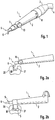
- Fig. 3a bis 3c
- die Arbeitsweise bei einer alternativen nicht erfindungsgemäßen Form des Handgeräts, bei der als Zwischenschritt eine Verdichtung des eingebrachten Füllungsmaterials vorgesehen ist, und
- Fig. 4a bis 4c
- die Arbeitsweise bei einer weiteren abgewandelten Form des Handgeräts.
- Fig. 1
- an embodiment of a hand-held device according to the invention in a perspective view;
- Fig. 2a and 2b
- the steps required in the filling of a dental cavity using the hand-held device according to the invention;
- Fig. 3a to 3c
- the operation of an alternative not inventive form of the handset, in which an intermediate step, a compression of the introduced filling material is provided, and
- Fig. 4a to 4c
- the operation in another modified form of the handset.
Das in
Primäre Aufgabe des Handgeräts 1 ist es zunächst, ein pastöses Füllungsmaterial anzugeben bzw. zur Verfügung zu stellen, mit dessen Hilfe Kavitäten insbesondere in Zähnen ausgefüllt werden können. Hierzu ist am vorderen Ende des Handgeräts 1 ein Applikationselement 5 ausgebildet, welches eine gegenüber der Längsachse der Griffhülse 2 seitlich abstehende Austrittsdüse 6 aufweist. Über diese Düse 6 wird das pastöse Füllungsmaterial bei Bedarf abgegeben.The primary task of the hand-held
Wie bereits aus der zuvor angesprochenen
Wie der Darstellung in
Eine andere denkbare Weiterbildung wäre die Verwendung mehrerer Vorratsbehälter mit Füllungsmaterialien unterschiedlicher Eigenschaften, bspw. unterschiedlicher Farben. Je nach Bedarf kann dann durch eine entsprechende Einstellung des Auswahlrings 8 ein geeigneter Vorratsbehälter ausgewählt werden, dessen Material dann mit Hilfe eines geeigneten Ausbringmechanismusses über die Austrittsdüse 6 in die Kavität eingebracht werden kann. Hierdurch besteht die Möglichkeit, jederzeit ein Material einzusetzen, welches sich hinsichtlich seiner äußeren Gestaltung in optimaler Weise an den zu behandelnden Zahn anpasst. Dieser Gedanke der Auswahl aus verschiedenen Füllungsmaterialien, der beispielsweise in Form eines Revolvermechanismusses realisiert werden kann, könnte insbesondere auch unabhängig von dem nachfolgend beschriebenen Gedanken der Ergänzung des Geräts 1 mit Bestrahlungsmitteln eingesetzt werden.Another conceivable development would be the use of multiple storage containers with filling materials of different properties, for example of different colors. Depending on requirements, a suitable reservoir can then be selected by a corresponding adjustment of the
Das bislang beschriebene Handgerät 1 dient also zum einen dazu, Füllungsmaterialien, mit deren Hilfe eine Zahnkavität ausgefüllt werden kann, zur Verfügung stellen. Wie bereits eingangs erwähnt wurde, weisen derartige Materialien oftmals die Eigenschaft auf, dass sie durch eine geeignete Bestrahlung effektiver ausgehärtet werden können. Um nunmehr während der Behandlung einen ständigen Wechsel zwischen unterschiedlichen Geräten zu vermeiden, ist das Handgerät 1 erfindungsgemäß mit Bestrahlungsmitteln ausgestattet, welche nachfolgend erläutert werden sollen.The hand-held
Die in
Die sich bei dem erfindungsgemäßen Handgerät 1 ergebende Arbeitsweise sowie die sich hierbei ergebenden Vorteile sollen nachfolgend anhand der
Die
Nachdem eine bestimmte Menge des Füllungsmaterials M eingebracht wurde, muss dieses - bevor weiteres Material eingebracht wird - zunächst ausgehärtet werden. Hierzu muss der Zahnarzt wie in
Aus den vorstehenden Schilderungen ergibt sich, dass - ohne das Gerät wechseln zu müssen - problemlos alternierend Material in die Kavität eingebracht und ausgehärtet werden kann. Diese Vorgehensweise ist dementsprechend mit einer verhältnismäßig hohen Zeitersparnis verbunden. Ferner muss auch nicht jedes Mal von Neuem das Handstück an dem Zahn angesetzt werden, wodurch die Handhabung deutlich vereinfacht wird.From the above descriptions it follows that - without having to change the device - easily alternating material can be introduced into the cavity and cured. This procedure is accordingly associated with a relatively high time savings. Furthermore, the handpiece does not have to be re-attached to the tooth every time, which considerably simplifies handling.
Die
Nachdem nunmehr entsprechend der Darstellung in
Auch bei dieser Ausführungsform ist kein Wechsel zwischen mehreren unterschiedlichen Geräte erforderlich, was wiederum zu einer sehr einfachen Durchführung der Prozedur führt.Also in this embodiment, no change between several different devices is required, which in turn leads to a very simple implementation of the procedure.
Ein erfindungsgemäßes Handgerät 1 ist in den
In einem weiteren Arbeitsschritt, der in
Diese besondere Vorgehensweise beruht auf der Erkenntnis, dass aufgrund der partiell sehr begrenzten Wärmeentwicklung und dem Aufbrechen chemischer Verbindungen mit Schall oder Ultraschallquellen derartige Komposite sehr leicht geschnitzt bzw. in Form gebracht werden können. Dieser Effekt wird nunmehr bei der Füllungstherapie ausgenutzt, um die hoch viskösen Füllungsmaterialien in die gewünschte anatomische Zahnform zu überführen.This particular approach is based on the recognition that due to the partially very limited heat development and the breaking up of chemical compounds with sound or ultrasound sources such composites can be carved or shaped very easily. This effect is now exploited in the filling therapy to transform the highly viscous filling materials into the desired anatomical tooth shape.
Das vorgeschlagene Verfahren stellt gegenüber der bisherigen Vorgehensweise einen deutlichen Fortschritt dar. Bei bisherigen Verfahren ist es notwendig, Füllungsmaterialüberschüsse über die Präparationsränder - insbesondere im Okklusalbereich - mit einem Spatel zu verteilen und in einem dünnen Film auf der Okklusalfläche auslaufen zu lassen bzw. idealerweise komplett zu entfernen. Da dies nicht immer vollständig gelingt, bzw. bei der Entfernung das Material in seiner Oberflächenkontinuität geschädigt wird, ist es nach der Aushärtung des Materials notwendig, dieses mit einem Schleifkörper zu entfernen. Dies ist zeitaufwändig und häufig wird dabei gesunde Zahnsubstanz ebenfalls abgetragen. Des weiteren ist die Modellation schwierig durchzuführen, da nur durch ein "Verdrücken" der Füllungsmasse die entsprechende anatomische Zahnform nur schwer wiederhergestellt werden kann.The proposed method represents a significant advance over the previous procedure. In previous methods, it is necessary to distribute filling material surpluses over the preparation margins - in particular in the occlusal area - with a spatula and let it expire in a thin film on the occlusal surface or ideally completely closed remove. Since this is not always completely successful, or the removal of the material in its surface continuity is damaged, it is necessary after curing of the material to remove this with a grinding wheel. This is time consuming and often healthy tooth substance is also removed. Furthermore, the modeling is difficult to perform because only by a "swelling" of the filling mass, the corresponding anatomical tooth shape can be restored only with difficulty.
Bei dem in den
Die Modellationsspitze 15 erfüllt im dargestellten Beispiel eine Doppelfunktion, da sie gleichzeitig auch als Verschlusskappe für die Komposite-Kartuschen eingesetzt werden kann. Hierbei erfolgt die Transmission der Schall- oder Ultraschallwellen über die Kartusche an die Verschlusskappe.The
Nach dem Bearbeiten des Füllungsmaterials M wird dieses dann ausgehärtet, wozu wiederum die an dem Handgerät 1 angeordnete - in den Figuren nicht dargestellte - Lichtquelle genutzt werden kann. Der in den
Insgesamt gesehen wird dementsprechend die Durchführung einer Behandlung für den Zahnarzt wesentlich vereinfacht. Ferner besteht aufgrund der unterschiedlichen Auswahlmöglichkeiten hinsichtlich der Viskosität bzw. der Materialeigenschaften des Füllungsmaterials die Möglichkeit, den Zahn mit einem jeweils speziell geeigneten Material auszufüllen. Die Qualität der Behandlung wird hierbei also deutlich erhöht.Overall, accordingly, the implementation of a treatment for the dentist is greatly simplified. Furthermore, due to the different choices with regard to the viscosity or the material properties of the filling material, it is possible to fill the tooth with a specially suitable material. The quality of the treatment is thus significantly increased.
Claims (9)
- A hand-held device (1), in particular for dental purposes,
having means located on the hand-held device (1) for emitting radiation that effects hardening of the filling material (M),
means for dispensing a pasty filling material (M), wherein the means for dispensing the filling material (M) comprise an outlet nozzle (6) located at the front end of the hand-held device (1),
characterised in that
the hand-held device (1) has a modelling tip (15), which can be attached at the outlet nozzle (6), for working the filling material (M), wherein sonic or ultrasonic oscillations can be applied to the modelling tip (15) by way of a drive unit located in the hand-held device (1). - A hand-held device according to claim 1,
characterised in that
the means for emitting radiation are formed by a light source (10), for example an LED or laser diode. - A hand-held device according to one of the preceding claims,
characterised in that
the modelling tip (15) has a conical shape. - A hand-held device according to one of the preceding claims,
characterised in that
the outlet nozzle (6) is formed in such a way that the filling material (M) is dispensed laterally with respect to a longitudinal axis of the hand-held device (1). - A hand-held device according to claim 4,
characterised in that
the means for emitting radiation are formed in such a way that the emission of the radiation (S) with regard to the longitudinal axis of the hand-held device (1) is effected so as to be offset, preferably so as to be offset by 90°, with respect to the dispensing of the filling material (M). - A hand-held device according to one of the previous claims,
characterised by
means for adjusting the viscosity of the filling material (M) that is dispensed. - A hand-held device according to one of the previous claims,
characterised by
means for selectively opening or closing a discharge channel for the filling material (M). - A hand-held device according to one of the previous claims,
characterised by
a plurality of storage containers for filling materials (M) having different properties and also selection means for selectively discharging one of the filling materials (M). - A hand-held device according to claim 8,
characterised in that
the hand-held device has means for selecting and changing the viscosity of the filling material (M) that is discharged.
Applications Claiming Priority (2)
| Application Number | Priority Date | Filing Date | Title |
|---|---|---|---|
| DE102007022205A DE102007022205A1 (en) | 2007-05-11 | 2007-05-11 | Hand-held device for dispensing a pasty filling material |
| PCT/EP2008/003705 WO2008138545A2 (en) | 2007-05-11 | 2008-05-08 | Hand-held device for dispensing a pasty filling material |
Publications (2)
| Publication Number | Publication Date |
|---|---|
| EP2144574A2 EP2144574A2 (en) | 2010-01-20 |
| EP2144574B1 true EP2144574B1 (en) | 2017-08-09 |
Family
ID=38761163
Family Applications (1)
| Application Number | Title | Priority Date | Filing Date |
|---|---|---|---|
| EP08749398.7A Active EP2144574B1 (en) | 2007-05-11 | 2008-05-08 | Hand-held device for dispensing a pasty filling material |
Country Status (4)
| Country | Link |
|---|---|
| US (1) | US8469707B2 (en) |
| EP (1) | EP2144574B1 (en) |
| DE (1) | DE102007022205A1 (en) |
| WO (1) | WO2008138545A2 (en) |
Families Citing this family (13)
| Publication number | Priority date | Publication date | Assignee | Title |
|---|---|---|---|---|
| DE102009013000A1 (en) * | 2009-03-13 | 2010-09-16 | Kaltenbach & Voigt Gmbh | Hand device for dispensing a pasty filling material |
| US20120122054A1 (en) * | 2009-07-09 | 2012-05-17 | Kaltenbach & Voigt Gmbh | Container for Dispensing a Pasty Filling Compound for Use with a Hand-held Device and Hand-held Device |
| ATE533427T1 (en) * | 2009-12-10 | 2011-12-15 | W & H Dentalwerk Buermoos Gmbh | MEDICAL, IN PARTICULAR DENTAL, TREATMENT DEVICE FOR DELIVERING A MEDIUM |
| US9452027B2 (en) * | 2009-12-10 | 2016-09-27 | Kerrhawe Sa | Dental composite applicator and related methods |
| EP2529690A1 (en) | 2011-05-31 | 2012-12-05 | Denpen I/S | Dental applicator tip and applicator tool |
| DE202012102583U1 (en) | 2012-07-12 | 2012-11-05 | Dinko Jurcevic | Dosing device for chemical composite material |
| DE102012018384A1 (en) * | 2012-09-18 | 2014-03-20 | Ivoclar Vivadent Ag | Device and method for the application of composites |
| WO2014165551A1 (en) | 2013-04-01 | 2014-10-09 | Pathy Vinod V | Lighting device |
| USD938095S1 (en) | 2013-04-01 | 2021-12-07 | Pathy Medical, Llc | Lighting device |
| US9925026B2 (en) | 2014-07-21 | 2018-03-27 | Kerr Corporation | Adapters, tips, and dental assemblies |
| EP3193776B1 (en) | 2014-09-17 | 2022-01-05 | Garrison Dental Solutions LLC | Dental curing light |
| USD810293S1 (en) | 2017-01-20 | 2018-02-13 | Garrison Dental Solutions, Llc | Dental instrument |
| JP2020529873A (en) * | 2017-02-22 | 2020-10-15 | インター—メッド インク | Heating of dental materials using overtone features, dye absorption, and material properties |
Family Cites Families (53)
| Publication number | Priority date | Publication date | Assignee | Title |
|---|---|---|---|---|
| US3221409A (en) * | 1961-12-12 | 1965-12-07 | Charles J Thiel | Amalgam dispenser |
| US3487828A (en) * | 1967-03-06 | 1970-01-06 | A J Armstrong Co Inc | Spray nozzle |
| US3552021A (en) * | 1969-04-09 | 1971-01-05 | Joseph A Graceffo | Compacting device for dental amalgam |
| US3667454A (en) * | 1970-06-12 | 1972-06-06 | Larry W Prince | Toothbrush with ultraviolet emitter |
| US3850346A (en) * | 1972-04-10 | 1974-11-26 | Cambridge Res & Dev Group | Hand squeezable, plural chambered, liquid dispenser |
| FR2255041B1 (en) * | 1973-12-24 | 1977-06-10 | Hirdes Rudigar | |
| US4076148A (en) * | 1976-10-13 | 1978-02-28 | Carse Clifford C | Multiple fluid dispenser with mechanical valve |
| US4291685A (en) * | 1979-06-15 | 1981-09-29 | Taelman Dennis L | Therapeutic heat and cosmetic applicator |
| DE3533367C1 (en) * | 1985-09-19 | 1987-02-05 | Hirdes Ruediger | Device for filling tooth cavities |
| US4673353A (en) | 1986-05-30 | 1987-06-16 | Nevin Donald M | Apparatus for applying a light-curable dental composition |
| JPS63183051A (en) * | 1987-01-26 | 1988-07-28 | 高津 寿夫 | Ultrasonic vibration applied closing and shaping system for dental adhesive molding material |
| FR2612764B1 (en) * | 1987-03-26 | 1989-06-30 | Werly Marc | METHOD FOR SEALING A DENTAL CAVITY AND TOOL FOR IMPLEMENTING THE METHOD |
| US5003434A (en) * | 1988-09-30 | 1991-03-26 | Den-Tal-Ez, Inc. | Miniature hand-held spot source of illumination |
| US5415543A (en) * | 1993-12-20 | 1995-05-16 | Rozmajzl, Jr.; William F. | Dental composite curing apparatus and method |
| EP0688543B1 (en) * | 1994-06-22 | 1999-12-15 | Koninklijke Philips Electronics N.V. | Teeth cleaning device with a hand-piece |
| US5547374A (en) * | 1994-10-21 | 1996-08-20 | Coleman; Thomas A. | Rate controlled fluid delivery in dental applications |
| DE29517958U1 (en) * | 1995-11-13 | 1997-03-20 | Muehlbauer Ernst Kg | Device for the incremental build-up of a tooth filling |
| DE19619155C2 (en) | 1995-12-22 | 1998-11-12 | Heraeus Kulzer Gmbh | Irradiation device for curing plastics, as well as processes and uses |
| ATE210413T1 (en) | 1995-12-22 | 2001-12-15 | Heraeus Kulzer Gmbh & Co Kg | METHOD FOR OPERATING A RADIATION DEVICE FOR CURING PLASTIC |
| EP0780103A3 (en) | 1995-12-22 | 1997-12-03 | Heraeus Kulzer GmbH | Irradiation apparatus |
| US5927977A (en) * | 1996-11-27 | 1999-07-27 | Professional Dental Technologies, Inc. | Dental scaler |
| JPH10337292A (en) * | 1997-06-09 | 1998-12-22 | Nakanishi:Kk | Dental hand piece |
| US6200134B1 (en) * | 1998-01-20 | 2001-03-13 | Kerr Corporation | Apparatus and method for curing materials with radiation |
| US5961235A (en) * | 1998-03-05 | 1999-10-05 | Kennedy; Patricia T. | Lotion applicator with handle reservoir |
| DE19825262A1 (en) * | 1998-06-05 | 1999-12-09 | Kaltenbach & Voigt | Method, device and means for removing caries in a cavity |
| WO2000026135A1 (en) * | 1998-11-05 | 2000-05-11 | Graco Inc. | Rotary vibrating applicator for viscous materials |
| DE10001513B4 (en) | 1999-09-09 | 2007-07-12 | Tilse, Rainer, Dr.med.dent. | Process for preparing and hand-held device for filling a synthetic resin-based dental filling material into a cavity of a tooth |
| US6386866B1 (en) * | 1999-11-12 | 2002-05-14 | Dentsply Research & Development Corp. | Ultrasonic dental insert and handpiece having a light source |
| US6494714B1 (en) * | 2000-01-24 | 2002-12-17 | Dentsply Research & Development Corp. | Method of making a tool tip and tool tip |
| US6312254B1 (en) * | 2000-09-22 | 2001-11-06 | Joshua Friedman | Dispenser for heating and extruding dental material |
| US6305934B1 (en) * | 2000-10-11 | 2001-10-23 | Bill H. Hatley, Jr. | Multifunction syringe for repairing teeth |
| US6454566B1 (en) * | 2000-11-13 | 2002-09-24 | Curozone Ireland Limited | Apparatus for the treatment of dental caries |
| US6648641B1 (en) * | 2000-11-22 | 2003-11-18 | The Procter & Gamble Company | Apparatus, method and product for treating teeth |
| US7086861B2 (en) * | 2002-03-01 | 2006-08-08 | Pitz Richard J | System for dispensing viscous materials |
| WO2004008982A2 (en) * | 2002-07-22 | 2004-01-29 | Innovative Dental Technologies, Inc. | Impactor and paste feeder |
| US6769573B1 (en) * | 2002-09-13 | 2004-08-03 | Randal N. Kazarian | Multi-chambered container fluid selection valve |
| EP1572022A1 (en) * | 2002-12-18 | 2005-09-14 | Paolo Fornasari | Abrasive tool for dental use |
| ITBO20030021A1 (en) * | 2003-01-17 | 2004-07-18 | Cefla Soc Coop A R L Ora Cefla Societa Cooperat | POLYMERIZING LAMP FOR THE POLYMERIZATION OF COMPOUNDS |
| WO2005005030A1 (en) * | 2003-06-30 | 2005-01-20 | Office Of The Staff Judge Advocate U.S. Army Research And Material Command | Drinking container, including a mixing device for the introduction of additives |
| US20050130099A1 (en) * | 2003-12-15 | 2005-06-16 | Kerrhawe Sa | Instrument for distributing restorative material on a tooth surface |
| US20080213731A1 (en) * | 2004-02-11 | 2008-09-04 | Cotesworth Fishburne | Devices and methods of applying dental composites |
| SE527301C2 (en) * | 2004-06-11 | 2006-02-07 | Dendema Ab | A tool for making a tooth filling |
| US20050282102A1 (en) * | 2004-06-16 | 2005-12-22 | Cms-Dental Aps | Kit for use by dental professionals |
| CN101014295A (en) * | 2004-07-02 | 2007-08-08 | 底斯柯斯牙齿印模公司 | Curing light device having a reflector |
| KR100668424B1 (en) * | 2005-02-04 | 2007-01-12 | 주식회사 메타바이오메드 | Cordless complex root canal plugger for dental clinic |
| US20060183071A1 (en) * | 2005-02-11 | 2006-08-17 | Pei-Hsien Hsuch | Phototherapeutic toothbrush |
| US20060234185A1 (en) * | 2005-02-17 | 2006-10-19 | Discus Dental Impressions Inc. | Ultrasonic dental tool having a light source |
| US7487889B2 (en) * | 2005-04-25 | 2009-02-10 | Owens James A | Variably proportional mixing device |
| US7270439B2 (en) * | 2005-06-13 | 2007-09-18 | Horrell Robin S | Compact lighting system attachable to a surgical tool and method of use thereof |
| DE102005028925A1 (en) | 2005-06-22 | 2007-01-04 | Kaltenbach & Voigt Gmbh | Hand-held device, in particular for dental purposes, for dispensing a pasty filling material |
| WO2007003063A1 (en) * | 2005-07-01 | 2007-01-11 | Medmix Systems Ag | Multicomponent dispensing device with valve assembly |
| US20070080170A1 (en) * | 2005-10-11 | 2007-04-12 | Atanu Saha | Condiment dispenser |
| EP1913864A1 (en) * | 2006-10-15 | 2008-04-23 | Medic.Nrg Ltd. | Illuminator for medical use |
-
2007
- 2007-05-11 DE DE102007022205A patent/DE102007022205A1/en not_active Withdrawn
-
2008
- 2008-05-08 US US12/599,767 patent/US8469707B2/en active Active
- 2008-05-08 WO PCT/EP2008/003705 patent/WO2008138545A2/en active Application Filing
- 2008-05-08 EP EP08749398.7A patent/EP2144574B1/en active Active
Also Published As
| Publication number | Publication date |
|---|---|
| WO2008138545A2 (en) | 2008-11-20 |
| EP2144574A2 (en) | 2010-01-20 |
| US8469707B2 (en) | 2013-06-25 |
| WO2008138545A3 (en) | 2009-01-08 |
| DE102007022205A1 (en) | 2008-11-13 |
| US20100304322A1 (en) | 2010-12-02 |
Similar Documents
| Publication | Publication Date | Title |
|---|---|---|
| EP2144574B1 (en) | Hand-held device for dispensing a pasty filling material | |
| EP2535016B1 (en) | Hand-held device, in particular for dental purposes, for dispensing a paste filler | |
| EP1210025B1 (en) | Instrument for introducing a dental filling material with a synthetic-resin base into a tooth cavity | |
| DE60130139T2 (en) | DENTAL MILLING ARRANGEMENT AND METHOD FOR THE PRODUCTION THEREOF | |
| EP2741897B1 (en) | Set for processing a light-curing material | |
| EP2335638B1 (en) | Medical, in particular dental, treatment device for dispensing a medium | |
| EP2405849B1 (en) | Manual device for dispensing a pasty filler | |
| DE102005021261A1 (en) | Dental cleaning method and tooth cleaning device with ultrasound | |
| DE102013107548A1 (en) | Dosing apparatus for manually controlled dosing of a light-curing material | |
| EP2140830A1 (en) | Medical handpiece for delivering a filling compound | |
| DE102013216855B4 (en) | Device and method for the production of shaped bodies | |
| EP3254641B1 (en) | Method for producing an attachment of a radiation curing device, attachment and dental restoration producing device | |
| DE102011003892A1 (en) | Method for producing at least one patient-specific, modularly constructed bracket and associated bracket | |
| DE102011003893A1 (en) | Method of making a patient-specific pad and associated pad | |
| DE10001513B4 (en) | Process for preparing and hand-held device for filling a synthetic resin-based dental filling material into a cavity of a tooth | |
| EP2762103B1 (en) | System and method for distribution of a dental composition | |
| EP3446654A1 (en) | Method for producing a single dental prosthesis structure with a 3-d printer, 3d printer for producing a single dental prosthesis structure and single dental prosthesis structure | |
| DE19751032A1 (en) | Dentistry aid with matrix having cover and wedge | |
| EP1432522B1 (en) | Applicator | |
| EP2451377A2 (en) | Container for dispensing a pasty filling compound for use with a hand-held device and hand-held device | |
| EP3595577B1 (en) | Endodontic pin | |
| DE102011008120B3 (en) | Incus-stapes-rail for use during repairing of defects of elongated extension unit of incus, has ridge provided on convex surface, where form of rail corresponds to semi-tube that is curved, during longitudinal extension of rail | |
| DE1766232A1 (en) | Dental handpiece | |
| DE7719858U (en) | Cap that can be placed on a beam exit opening of an energy conductor |
Legal Events
| Date | Code | Title | Description |
|---|---|---|---|
| PUAI | Public reference made under article 153(3) epc to a published international application that has entered the european phase |
Free format text: ORIGINAL CODE: 0009012 |
|
| 17P | Request for examination filed |
Effective date: 20091110 |
|
| AK | Designated contracting states |
Kind code of ref document: A2 Designated state(s): AT BE BG CH CY CZ DE DK EE ES FI FR GB GR HR HU IE IS IT LI LT LU LV MC MT NL NO PL PT RO SE SI SK TR |
|
| AX | Request for extension of the european patent |
Extension state: AL BA MK RS |
|
| 17Q | First examination report despatched |
Effective date: 20100223 |
|
| DAX | Request for extension of the european patent (deleted) | ||
| RIC1 | Information provided on ipc code assigned before grant |
Ipc: A61C 1/07 20060101ALI20161012BHEP Ipc: A61C 19/00 20060101ALI20161012BHEP Ipc: A61C 5/06 20060101AFI20161012BHEP Ipc: A61C 13/15 20060101ALI20161012BHEP |
|
| GRAP | Despatch of communication of intention to grant a patent |
Free format text: ORIGINAL CODE: EPIDOSNIGR1 |
|
| STAA | Information on the status of an ep patent application or granted ep patent |
Free format text: STATUS: GRANT OF PATENT IS INTENDED |
|
| INTG | Intention to grant announced |
Effective date: 20161219 |
|
| GRAS | Grant fee paid |
Free format text: ORIGINAL CODE: EPIDOSNIGR3 |
|
| REG | Reference to a national code |
Ref country code: DE Ref legal event code: R079 Ref document number: 502008015517 Country of ref document: DE Free format text: PREVIOUS MAIN CLASS: A61C0019000000 Ipc: A61C0005600000 |
|
| GRAA | (expected) grant |
Free format text: ORIGINAL CODE: 0009210 |
|
| STAA | Information on the status of an ep patent application or granted ep patent |
Free format text: STATUS: THE PATENT HAS BEEN GRANTED |
|
| RIC1 | Information provided on ipc code assigned before grant |
Ipc: A61C 19/00 20060101ALI20170629BHEP Ipc: A61C 5/60 20170101AFI20170629BHEP Ipc: A61C 1/07 20060101ALI20170629BHEP |
|
| AK | Designated contracting states |
Kind code of ref document: B1 Designated state(s): AT BE BG CH CY CZ DE DK EE ES FI FR GB GR HR HU IE IS IT LI LT LU LV MC MT NL NO PL PT RO SE SI SK TR |
|
| REG | Reference to a national code |
Ref country code: GB Ref legal event code: FG4D Free format text: NOT ENGLISH |
|
| REG | Reference to a national code |
Ref country code: CH Ref legal event code: EP Ref country code: CH Ref legal event code: NV Representative=s name: RIEDERER HASLER AND PARTNER PATENTANWAELTE AG, CH Ref country code: AT Ref legal event code: REF Ref document number: 915965 Country of ref document: AT Kind code of ref document: T Effective date: 20170815 |
|
| REG | Reference to a national code |
Ref country code: IE Ref legal event code: FG4D Free format text: LANGUAGE OF EP DOCUMENT: GERMAN |
|
| REG | Reference to a national code |
Ref country code: DE Ref legal event code: R096 Ref document number: 502008015517 Country of ref document: DE |
|
| REG | Reference to a national code |
Ref country code: NL Ref legal event code: MP Effective date: 20170809 |
|
| REG | Reference to a national code |
Ref country code: LT Ref legal event code: MG4D |
|
| PG25 | Lapsed in a contracting state [announced via postgrant information from national office to epo] |
Ref country code: NO Free format text: LAPSE BECAUSE OF FAILURE TO SUBMIT A TRANSLATION OF THE DESCRIPTION OR TO PAY THE FEE WITHIN THE PRESCRIBED TIME-LIMIT Effective date: 20171109 Ref country code: SE Free format text: LAPSE BECAUSE OF FAILURE TO SUBMIT A TRANSLATION OF THE DESCRIPTION OR TO PAY THE FEE WITHIN THE PRESCRIBED TIME-LIMIT Effective date: 20170809 Ref country code: HR Free format text: LAPSE BECAUSE OF FAILURE TO SUBMIT A TRANSLATION OF THE DESCRIPTION OR TO PAY THE FEE WITHIN THE PRESCRIBED TIME-LIMIT Effective date: 20170809 Ref country code: LT Free format text: LAPSE BECAUSE OF FAILURE TO SUBMIT A TRANSLATION OF THE DESCRIPTION OR TO PAY THE FEE WITHIN THE PRESCRIBED TIME-LIMIT Effective date: 20170809 Ref country code: FI Free format text: LAPSE BECAUSE OF FAILURE TO SUBMIT A TRANSLATION OF THE DESCRIPTION OR TO PAY THE FEE WITHIN THE PRESCRIBED TIME-LIMIT Effective date: 20170809 Ref country code: NL Free format text: LAPSE BECAUSE OF FAILURE TO SUBMIT A TRANSLATION OF THE DESCRIPTION OR TO PAY THE FEE WITHIN THE PRESCRIBED TIME-LIMIT Effective date: 20170809 |
|
| PG25 | Lapsed in a contracting state [announced via postgrant information from national office to epo] |
Ref country code: LV Free format text: LAPSE BECAUSE OF FAILURE TO SUBMIT A TRANSLATION OF THE DESCRIPTION OR TO PAY THE FEE WITHIN THE PRESCRIBED TIME-LIMIT Effective date: 20170809 Ref country code: BG Free format text: LAPSE BECAUSE OF FAILURE TO SUBMIT A TRANSLATION OF THE DESCRIPTION OR TO PAY THE FEE WITHIN THE PRESCRIBED TIME-LIMIT Effective date: 20171109 Ref country code: PL Free format text: LAPSE BECAUSE OF FAILURE TO SUBMIT A TRANSLATION OF THE DESCRIPTION OR TO PAY THE FEE WITHIN THE PRESCRIBED TIME-LIMIT Effective date: 20170809 Ref country code: ES Free format text: LAPSE BECAUSE OF FAILURE TO SUBMIT A TRANSLATION OF THE DESCRIPTION OR TO PAY THE FEE WITHIN THE PRESCRIBED TIME-LIMIT Effective date: 20170809 Ref country code: GR Free format text: LAPSE BECAUSE OF FAILURE TO SUBMIT A TRANSLATION OF THE DESCRIPTION OR TO PAY THE FEE WITHIN THE PRESCRIBED TIME-LIMIT Effective date: 20171110 Ref country code: IS Free format text: LAPSE BECAUSE OF FAILURE TO SUBMIT A TRANSLATION OF THE DESCRIPTION OR TO PAY THE FEE WITHIN THE PRESCRIBED TIME-LIMIT Effective date: 20171209 |
|
| PG25 | Lapsed in a contracting state [announced via postgrant information from national office to epo] |
Ref country code: RO Free format text: LAPSE BECAUSE OF FAILURE TO SUBMIT A TRANSLATION OF THE DESCRIPTION OR TO PAY THE FEE WITHIN THE PRESCRIBED TIME-LIMIT Effective date: 20170809 Ref country code: DK Free format text: LAPSE BECAUSE OF FAILURE TO SUBMIT A TRANSLATION OF THE DESCRIPTION OR TO PAY THE FEE WITHIN THE PRESCRIBED TIME-LIMIT Effective date: 20170809 Ref country code: CZ Free format text: LAPSE BECAUSE OF FAILURE TO SUBMIT A TRANSLATION OF THE DESCRIPTION OR TO PAY THE FEE WITHIN THE PRESCRIBED TIME-LIMIT Effective date: 20170809 |
|
| REG | Reference to a national code |
Ref country code: DE Ref legal event code: R097 Ref document number: 502008015517 Country of ref document: DE |
|
| REG | Reference to a national code |
Ref country code: FR Ref legal event code: PLFP Year of fee payment: 11 |
|
| PG25 | Lapsed in a contracting state [announced via postgrant information from national office to epo] |
Ref country code: SK Free format text: LAPSE BECAUSE OF FAILURE TO SUBMIT A TRANSLATION OF THE DESCRIPTION OR TO PAY THE FEE WITHIN THE PRESCRIBED TIME-LIMIT Effective date: 20170809 Ref country code: IT Free format text: LAPSE BECAUSE OF FAILURE TO SUBMIT A TRANSLATION OF THE DESCRIPTION OR TO PAY THE FEE WITHIN THE PRESCRIBED TIME-LIMIT Effective date: 20170809 Ref country code: EE Free format text: LAPSE BECAUSE OF FAILURE TO SUBMIT A TRANSLATION OF THE DESCRIPTION OR TO PAY THE FEE WITHIN THE PRESCRIBED TIME-LIMIT Effective date: 20170809 |
|
| PLBE | No opposition filed within time limit |
Free format text: ORIGINAL CODE: 0009261 |
|
| STAA | Information on the status of an ep patent application or granted ep patent |
Free format text: STATUS: NO OPPOSITION FILED WITHIN TIME LIMIT |
|
| 26N | No opposition filed |
Effective date: 20180511 |
|
| PG25 | Lapsed in a contracting state [announced via postgrant information from national office to epo] |
Ref country code: SI Free format text: LAPSE BECAUSE OF FAILURE TO SUBMIT A TRANSLATION OF THE DESCRIPTION OR TO PAY THE FEE WITHIN THE PRESCRIBED TIME-LIMIT Effective date: 20170809 |
|
| PG25 | Lapsed in a contracting state [announced via postgrant information from national office to epo] |
Ref country code: MT Free format text: LAPSE BECAUSE OF FAILURE TO SUBMIT A TRANSLATION OF THE DESCRIPTION OR TO PAY THE FEE WITHIN THE PRESCRIBED TIME-LIMIT Effective date: 20170809 |
|
| GBPC | Gb: european patent ceased through non-payment of renewal fee |
Effective date: 20180508 |
|
| REG | Reference to a national code |
Ref country code: BE Ref legal event code: MM Effective date: 20180531 |
|
| PG25 | Lapsed in a contracting state [announced via postgrant information from national office to epo] |
Ref country code: MC Free format text: LAPSE BECAUSE OF FAILURE TO SUBMIT A TRANSLATION OF THE DESCRIPTION OR TO PAY THE FEE WITHIN THE PRESCRIBED TIME-LIMIT Effective date: 20170809 |
|
| REG | Reference to a national code |
Ref country code: IE Ref legal event code: MM4A |
|
| PG25 | Lapsed in a contracting state [announced via postgrant information from national office to epo] |
Ref country code: LU Free format text: LAPSE BECAUSE OF NON-PAYMENT OF DUE FEES Effective date: 20180508 |
|
| PG25 | Lapsed in a contracting state [announced via postgrant information from national office to epo] |
Ref country code: IE Free format text: LAPSE BECAUSE OF NON-PAYMENT OF DUE FEES Effective date: 20180508 Ref country code: GB Free format text: LAPSE BECAUSE OF NON-PAYMENT OF DUE FEES Effective date: 20180508 |
|
| PG25 | Lapsed in a contracting state [announced via postgrant information from national office to epo] |
Ref country code: BE Free format text: LAPSE BECAUSE OF NON-PAYMENT OF DUE FEES Effective date: 20180531 |
|
| REG | Reference to a national code |
Ref country code: DE Ref legal event code: R082 Ref document number: 502008015517 Country of ref document: DE Representative=s name: MITSCHERLICH, PATENT- UND RECHTSANWAELTE PARTM, DE Ref country code: DE Ref legal event code: R081 Ref document number: 502008015517 Country of ref document: DE Owner name: KAVO DENTAL GMBH, DE Free format text: FORMER OWNER: KALTENBACH & VOIGT GMBH, 88400 BIBERACH, DE |
|
| PG25 | Lapsed in a contracting state [announced via postgrant information from national office to epo] |
Ref country code: TR Free format text: LAPSE BECAUSE OF FAILURE TO SUBMIT A TRANSLATION OF THE DESCRIPTION OR TO PAY THE FEE WITHIN THE PRESCRIBED TIME-LIMIT Effective date: 20170809 |
|
| PG25 | Lapsed in a contracting state [announced via postgrant information from national office to epo] |
Ref country code: HU Free format text: LAPSE BECAUSE OF FAILURE TO SUBMIT A TRANSLATION OF THE DESCRIPTION OR TO PAY THE FEE WITHIN THE PRESCRIBED TIME-LIMIT; INVALID AB INITIO Effective date: 20080508 Ref country code: PT Free format text: LAPSE BECAUSE OF FAILURE TO SUBMIT A TRANSLATION OF THE DESCRIPTION OR TO PAY THE FEE WITHIN THE PRESCRIBED TIME-LIMIT Effective date: 20170809 |
|
| PG25 | Lapsed in a contracting state [announced via postgrant information from national office to epo] |
Ref country code: CY Free format text: LAPSE BECAUSE OF FAILURE TO SUBMIT A TRANSLATION OF THE DESCRIPTION OR TO PAY THE FEE WITHIN THE PRESCRIBED TIME-LIMIT Effective date: 20170809 |
|
| REG | Reference to a national code |
Ref country code: AT Ref legal event code: PC Ref document number: 915965 Country of ref document: AT Kind code of ref document: T Owner name: KAVO DENTAL GMBH, DE Effective date: 20220530 |
|
| PGFP | Annual fee paid to national office [announced via postgrant information from national office to epo] |
Ref country code: FR Payment date: 20230309 Year of fee payment: 16 |
|
| PGFP | Annual fee paid to national office [announced via postgrant information from national office to epo] |
Ref country code: DE Payment date: 20230314 Year of fee payment: 16 Ref country code: CH Payment date: 20230602 Year of fee payment: 16 |
|
| PGFP | Annual fee paid to national office [announced via postgrant information from national office to epo] |
Ref country code: AT Payment date: 20230425 Year of fee payment: 16 |