EP2762103B1 - System and method for distribution of a dental composition - Google Patents
System and method for distribution of a dental composition Download PDFInfo
- Publication number
- EP2762103B1 EP2762103B1 EP14150566.9A EP14150566A EP2762103B1 EP 2762103 B1 EP2762103 B1 EP 2762103B1 EP 14150566 A EP14150566 A EP 14150566A EP 2762103 B1 EP2762103 B1 EP 2762103B1
- Authority
- EP
- European Patent Office
- Prior art keywords
- composite capsule
- capsule
- composite
- dispensing
- support surface
- Prior art date
- Legal status (The legal status is an assumption and is not a legal conclusion. Google has not performed a legal analysis and makes no representation as to the accuracy of the status listed.)
- Not-in-force
Links
Images


Classifications
-
- A—HUMAN NECESSITIES
- A61—MEDICAL OR VETERINARY SCIENCE; HYGIENE
- A61C—DENTISTRY; APPARATUS OR METHODS FOR ORAL OR DENTAL HYGIENE
- A61C5/00—Filling or capping teeth
- A61C5/60—Devices specially adapted for pressing or mixing capping or filling materials, e.g. amalgam presses
- A61C5/66—Capsules for filling material
-
- A—HUMAN NECESSITIES
- A61—MEDICAL OR VETERINARY SCIENCE; HYGIENE
- A61C—DENTISTRY; APPARATUS OR METHODS FOR ORAL OR DENTAL HYGIENE
- A61C5/00—Filling or capping teeth
- A61C5/60—Devices specially adapted for pressing or mixing capping or filling materials, e.g. amalgam presses
- A61C5/62—Applicators, e.g. syringes or guns
Definitions
- the invention relates to a system comprising a composite capsule for receiving and dispensing a dental material, a supply syringe and a dispensing gun according to the preamble of claim 1.
- the composite capsule comprises a receiving space surrounded by a capsule wall, which extends between a receiving opening and an outlet opening wherein the outlet opening is arranged at a front end of the receiving space and the receiving opening at a rear end of the receiving space.
- a support surface oriented in the direction of the front end projects outwards in relation to the capsule wall.
- the invention also relates to a method for dispensing a dental material using such a system.
- Such composite capsules are used to selectively apply a dental material, as used for example for filling cavities in teeth, to a desired location in the mouth of a patient.
- a dental material as used for example for filling cavities in teeth
- the dental material exits through the exit opening and can be applied by the dentist at the desired location.
- a composite capsule can be inserted into a dispensing gun.
- the dispensing gun includes a plunger that can be used to pressurize the dental material in the composite capsule so that it exits through the exit orifice.
- the composite capsule With the support surface, the composite capsule is supported on a counter surface of the dispensing gun, whereby the composite capsule is held against the force of the plunger in its position in the dispensing gun.
- Such a system of composite capsule, dispensing gun and syringe is from the US 5,122,057 known.
- a syringe attachment for applying a dental material is disclosed.
- the composite capsules are pre-filled units containing a fixed amount of dental material. Only in very few cases corresponds to this predetermined amount of dental material exactly the amount that the dentist needs. In most cases, excess dental material remains in the composite capsule, which must be disposed of as waste.
- the invention is based on the object to present a composite capsule, which can be used variable. Based on the cited prior art, the object is achieved with the features of independent claim 1. Advantageous embodiments can be found in the subclaims.
- the support surface is interrupted by a threaded recess.
- Threaded recess refers to a lying in a plane of the support surface area in which a portion of a counter-thread is arranged when the composite capsule is brought into engagement with the mating thread.
- the invention is based on the idea that the composite capsules are made available to the user without content and the user only brings in as much dental material in the composite capsule, as is required for the specific application.
- the composite capsule is designed so that it is easily possible for the user to introduce the dental material in the composite capsule.
- the support surface is interrupted by a threaded recess, it is possible, the composite capsule with a mating thread to engage. Via the threaded connection, the composite capsule can be brought into engagement with a storage container, for example a supply syringe, so that the desired amount of dental material can pass from the storage container into the composite capsule.
- the structure of the invention on the outside of the capsule wall is thus designed so that it fulfills a dual function.
- a counterforce is built up over the support surface when a force is exerted on the composite capsule via a plunger of a delivery pistol.
- a contamination of the reservoir for example by contact with the oral cavity of the patient, does not take place by the transport of the dental material in the composite capsule, so that in the reservoir remaining dental material can be used in a next treatment.
- the quantity of dental material conveyed into the composite capsule it is almost completely used up during the treatment, so that there is no or only very little excess dental material upon subsequent disposal or cleaning of the composite capsule which has to be disposed of.
- the support surface forms the front surface of a collar which extends around the circumference of the composite capsule.
- the waistband has a longitudinal extension of the composite capsule. Placing the collar in the rear of the capsule allows for easy handling of the composite capsule during connection to a reservoir or dispensing gun, since a large portion of the composite capsule can be grasped during the bonding process.
- the support surface preferably extends over a circumferential angle of at least 45 °, more preferably at least 90 °, more preferably at least 120 °, without being interrupted by a threaded recess. This provides a large area over which pressure can be transferred to a mating surface.
- the rear surface of the collar is also provided with a thread recess.
- the threaded recess in the rear surface may be arranged offset in the circumferential direction relative to the threaded recess in the front surface.
- the threaded recesses in the front surface and the rear surface are connected to each other via a thread groove. This increases the area in which a portion of a counter-thread can be engaged with the thread of the composite capsule. This allows a better grip between the composite capsule and the mating thread.
- a facilitated engagement between the composite capsule and the counter thread can be conveniently achieved in that the support surface is provided with a second threaded recess which can be brought into engagement with a corresponding second thread of a counter-thread.
- the second thread recess may also be provided a corresponding thread recess in the rear surface of the collar.
- the two threaded recesses can be connected to a second thread groove.
- the second thread recess of the support surface relative to the first threaded recess of the support surface in the circumferential direction is offset by an angle of 180 °.
- a piston which can be inserted through the receiving opening of the composite capsule in the receiving space.
- the outer diameter of the piston may be adapted to the diameter of the receiving space.
- the piston is used to mediate the pressure of the plunger the dispensing gun on the located in the cylindrical part of the receiving space dental material.
- the use of the piston is advantageous because the plunger does not come in this way in direct contact with the dental material and therefore does not need to be cleaned.
- the dental mass is introduced into the receiving space when the piston is not in the receiving space.
- the composite capsule can be made as a one-piece injection molded part of a plastic material.
- the material surrounding the receiving space can be transparent, so that it is visible from the outside how much dental material is contained in the receiving space. In order to protect the dental material from light, the transparent material may be colored.
- the capsule wall may have a portion in which the material of the capsule wall is transparent.
- the transparent section can be seen through the material of the capsule wall into the receiving space and, for example, recognize how much dental material is contained in the receiving space.
- the transparent section can partially or completely cover the receiving space. In the circumferential direction of the transparent portion may also partially or completely cover the receiving space.
- the composite capsule can be made entirely of transparent material.
- the material of the capsule wall may be formed in the transparent portion as an optical filter, which blocks short-wave portions of visible light and which is transparent to long-wave portions of visible light.
- the transition region between the stopband and the passband may, for example, be between 500 nm and 600 nm.
- the transparent material may appear orange.
- the optical filter also blocks UV light.
- the stop band of the optical filter may include, for example, the wavelength range of 370 nm to 520 nm. Such a filtering effect the transparent material is particularly advantageous when the dental material cures in the receiving space under UV light. Such dental materials are applied in a liquid or pasty state and then cured by irradiation with UV light within a short time.
- the composite capsule can be provided with a scale on which the amount of dental material contained can be read off.
- the receiving space may for example have a volume between 0.1 ml and 0.5 ml.
- the volume of the receiving space is between 0.12 ml and 0.2 ml.
- the receiving space may have a first portion in which the receiving space is cylindrical.
- the diameter of the cylindrical portion is preferably adapted to the diameter of the piston.
- Between the receiving opening and the cylindrical portion of the receiving space may have a second portion in which the interior widens in the direction of the receiving opening.
- the first section preferably transitions without paragraph into the second section.
- the reservoir can be provided with a matching tip to the expansion, so that the composite capsule can be easily attached to the reservoir.
- the tip of the reservoir is sized so that the exiting dental material passes into the cylindrical portion of the receiving space.
- a receiving space that has widened in the direction of the receiving opening may have independent inventive content.
- the composite capsule has a dispensing tip at its front end.
- the Ausbringspitze can taper in the direction of the outlet opening. Relative to the longitudinal axis of the receiving space, the Ausbringspitze is preferably inclined. The inclination may, for example, be such that the axis of the dispensing tip encloses an angle between 20 ° and 80 ° with the axis of the receiving space.
- Within the Ausbringspitze is conveniently a channel which extends from the receiving space to the outlet opening.
- the channel may for example have a diameter between 1 mm and 3 mm, preferably between 1.2 mm and 2.5 mm.
- the channel between the receiving space and the outlet opening has a constant diameter.
- the dispensing tip can be provided with a cannula through which dental material moves.
- the delivery tip may be oriented such that there is an overlap between projection of the delivery tip into the plane of the support surface and projection of the thread groove into the plane of the support surface. Further preferably, the projection of the Ausbringspitze cuts the threaded recess in the support surface. Such an orientation of the dispensing tip is advantageous in terms of a favorable orientation of the composite capsule within the dispensing gun, since the support surface is then not interrupted by the thread recess in the sections of the largest power transmission.
- a suitable cap may be provided, which can be plugged onto the applicator tip of the composite capsule.
- the storage syringe forms a reservoir for the dental material, from which the desired amount of dental material can be transferred into the composite capsule.
- the supply syringe has a mating thread which mates with the threaded recess of the composite capsule and which is arranged around an outlet opening of the supply syringe.
- the composite capsule can be connected to the supply syringe. From the outlet opening of the supply syringe escaping dental material then passes into the receiving space of the composite capsule.
- the mating thread may be formed as a standardized Luer-Lock thread and the threaded recess of the composite capsule may be designed so that it forms a threaded connection with the Luer-Lock thread.
- the outlet opening of the supply syringe is preferably arranged on a tapered tip of the storage syringe, wherein the tip further tapers conically, preferably.
- the mating thread may be disposed on a lateral surface surrounding the tip, wherein the supply syringe may be formed so that the collar of the composite capsule is disposed between the tip and the lateral surface when the threaded connection is engaged.
- the cone shape of the tip of the supply syringe can correspond to the standardized Luer cone.
- the flared portion of the composite capsule receiving space may conform to the cone shape of the tip so that there is surface contact when the composite capsule is attached to the tip.
- the tip may be longer than the widening portion, so that the front end of the tip extends into the cylindrical portion of the receiving space.
- the supply syringe preferably contains so much dental material that it is sufficient for filling a plurality of composite capsules.
- the dispensing gun is equipped according to the invention with a capsule receptacle for the composite capsule, wherein the capsule receptacle has a cooperating with the support surface of the composite capsule counter surface.
- a plunger can be used to apply pressure to the receiving space of the composite capsule so that the dental material emerges from the front end of the composite capsule.
- the composite capsule is held in position against the pressure of the plunger via the mating surface and the support surface.
- the counter surface is inventively provided with a recess through which the composite capsule can be passed in the radial direction to insert the composite capsule in the capsule receptacle.
- the capsule holder can be designed so that it surrounds the composite capsule in the manner of a snap-fit.
- the thread groove of the support surface is arranged according to the invention in the region of the recesses of the mating surface. This has the advantage that the support surface cooperates over those portions with the counter surface, which are not weakened by the thread furrow.
- the invention also relates to a method for dispensing a dental material using the system according to the invention.
- a composite capsule is connected to a reservoir, wherein the composite capsule is connected via a threaded connection to the reservoir.
- Dental material from the reservoir is applied so that it passes into a receiving space of the composite capsule.
- the receiving space is closed with a piston.
- the composite capsule is inserted into a capsule holder of a dispensing gun.
- the dispensing gun is actuated to apply pressure to the piston.
- the empty composite capsule is connected to the supply syringe by engaging the threaded recess of the composite capsule with the mating mating thread of the supply syringe.
- a suitable amount of dental material for the dental treatment is conveyed into the composite capsule.
- the connection between the composite capsule and the supply syringe is released and a piston is inserted through the receiving opening of the composite capsule into the receiving space.
- the composite capsule is inserted into the mating receptacle of the dispensing gun and a mechanism is actuated to move the plunger towards the composite capsule.
- the plunger then moves through the receiving opening of the composite capsule into the receiving space and exerts pressure on the piston and the dental material behind it, which moves in the direction of the outlet opening.
- the actuation of the mechanism for moving the plunger is metered so that a suitable amount of dental material emerges from the outlet opening.
- the method can be developed with further features which are described in the context of the composite capsule or the system according to the invention.
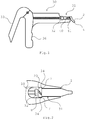
- An inventive system comprises according to the FIGS. 1 and 3 a composite capsule 1, a dispensing gun 30 and a supply syringe 50.
- the composite capsule 1 is connected to the dispensing gun 30.
- the dispensing gun 30 comprises a mechanism 33, by means of which a plunger 32 is pressed in the direction of a capsule receptacle 31 arranged at the front end of the dispensing gun 30.
- the dispensing gun 30 comprises a handle 36 which extends in the radial direction.
- the front surface of the plunger 32 is circular and has a diameter which is slightly smaller than the inner diameter of a receiving space 5 of the composite capsule 1.
- the plunger 32 and the receiving space 5 of the composite capsule 1 are arranged so that upon actuation of the mechanism 33 of the plunger 32 enters the receiving space 5 and exerts pressure on the piston 40 arranged therein.
- the piston 40 is thereby moved in the direction of the applicator tip 2 of the composite capsule 1 and thereby conveys the dental mass 41 located in the receiving space also in the direction of the dispensing tip 2. If the piston 40 pressed by the plunger 32 sufficiently far in the direction of the applicator tip 2, the Dental mass 41 from the outlet opening 4. It is easy for the dentist to specifically apply dental material in the mouth of a patient in this way.
- the composite capsule 1 comprises according to the FIGS. 4 and 5 a receiving space 5, which is bounded by a wall 6.
- the discharge tip 2 At the front end of the receiving space 5 is the discharge tip 2, which forms an angle of approximately 45 ° with the longitudinal axis of the receiving space 5.
- the receiving opening 9 At the rear end of the receiving space 5, the receiving opening 9 is arranged.
- the receiving space 5 has a front portion 15 in which the wall surface is shaped cylindrically is and a rear portion 16 in which the wall surface widens in the direction of the receiving opening 9.
- the discharge tip 2 comprises a channel 3, which extends from the receiving space 5 to the outlet opening 4 arranged at the front end of the discharge tip 2. According to Fig. 6 There is an overlap between the Ausbringspitze 2 and one of the threaded recesses 14 when the Ausbringspitze 2 is projected in the plane of the support surface.
- a collar 20 projects radially outward.
- the covenant is interrupted by two thread grooves 10, of which in FIG. 5 only one can be seen.
- the second thread groove is offset by 180 ° to the first thread groove in the circumferential direction around the collar around.
- the thread grooves 10 form an acute angle with the longitudinal axis of the composite capsule.
- the collar 20 has a cylindrical outer surface, wherein the cylinder axis along the longitudinal axis of the receiving space 5 is aligned.
- the composite capsule is manufactured as a one-piece injection molded part from a transparent plastic material.
- the plastic material acts as an optical filter that blocks short-wave visible light and UV light and is transparent to long-wavelength visible light.
- the optical filter is designed as an edge filter with a sharp transition between the passband and the stopband. The transition between the passband and the stopband is about 520 nm.
- the composite capsule looks orange to an observer.
- the receiving space 5 has a volume of 0.19 ml.
- the collar furthermore comprises a support surface 7 pointing towards the front end of the composite capsule 1 and a rear surface 8 pointing to the rear.
- the thread groove 10 opens into the rear surface 8 in a threaded recess 13 and in the support surface 7 in a threaded recess 14.
- the composite capsule 1 is delivered to the user without content and only filled by the user with a desired amount of dental material. If the dental material is introduced into the receiving space 5, a piston 40 is inserted through the receiving opening 9, so that the receiving space 5 is completed. If pressure is exerted on the piston 40 with the plunger 32 of the dispensing gun 30, it moves forward and presses the dental material in the direction of the outlet opening 4. If the dental compound 41 is not to be used immediately, the outlet opening 4 can be closed with a cap 11.
- the composite capsule 1 As in Fig. 3 shown connected to a supply syringe 50 containing a supply of dental material.
- the supply syringe 50 has at its front end a cone-shaped tip 52.
- Around the cone-shaped tip 52 extends around a lateral surface 51, on the inside of a sauer alloys thread 53 is formed.
- the cone-shaped tip 52 and the thread 53 are sized to conform to the Luer-Lock standard.
- the section 16 of the receiving space 5 of the composite capsule 1 is adapted to the Luer cone, so it lies flat on the top 52.
- the front end of the tip 52 projects into the section 15 of the receiving space 5.
- connection between the composite capsule 1 and the storage syringe 50 is made by the threaded grooves 10 of the composite capsule 1 are brought into engagement with the thread 53 of the storage syringe 50.
- the cone-shaped tip 52 then protrudes into the receiving space 5 of the composite capsule 1. If pressure is exerted on the piston 54 in the storage syringe 50 located dental mass 54, the dental material 54 passes through the opening of the cone-shaped tip 52 from.
- the composite capsule 1 is filled with a desired amount of dental material 54. After filling the composite capsule 1, this is separated from the supply syringe 50 and the piston 40 is inserted through the receiving opening 9 of the composite capsule 1.
- the composite capsule 1 is subsequently inserted into the capsule receptacle 31 of the dispensing gun 30.
- the capsule receptacle 31 is shown in a top view.
- the delivery tip 4 of the composite capsule 1 which in Fig. 1 pointing down, directed into the plane of the drawing.
- the capsule receptacle 31 comprises an insertion shaft for the composite capsule 1, in which the composite capsule 1 can be inserted from above.
- the lateral surfaces of the capsule holder determine the orientation of the composite capsule 1 and are designed so that the composite capsule 1 snaps into place by means of a snap fit.
- the longitudinal extension of the lateral surfaces is smaller than the distance between the support surface 7 and the front end of the composite capsule 1.
- the capsule receptacle 31 further comprises an end face 34 on which the support surface 7 of the capsule seat 31 inserted composite capsule 1 is applied.
- the end face 34 thus forms a counter surface to the support surface 7. This ensures that the composite capsule 1 is not pressed by the plunger 32 forward.
- the applicator tip 2 of the composite capsule 1 points in the same direction as the handle 36 of the applicator gun 30.
- One of the thread grooves 10 then lies according to Fig. 2 in the region of the capsule receptacle 31, in which the support surface 7 does not bear against the mating surface 34. Where the forces between the support surface 7 and the counter surface 34 are transmitted, the collar 20 is not weakened by a thread furrow.
- the collar 20 of the composite capsule 1 according to the invention thus has a dual function in that it is supported on the one hand on the mating surface 34 of the dispensing gun 30 and on the other hand enables the threaded connection with the thread 53.
- the receiving space 5 of the composite capsule 1 is designed so that it rests flat on the cone tip 52 of the storage syringe 50.
Description
Die Erfindung betrifft ein System aus einer Composite-Kapsel zum Aufnehmen und Abgeben einer Dentalmasse, einer Vorratsspritze sowie einer Ausbringpistole nach dem Oberbegriff des Anspruchs 1. Die Composite-Kapsel umfasst einen von einer Kapselwand umgebenen Aufnahmeraum, der sich zwischen einer Aufnahmeöffnung und einer Austrittsöffnung erstreckt, wobei die Austrittsöffnung an einem vorderen Ende des Aufnahmeraums und die Aufnahmeöffnung an einem hinteren Ende des Aufnahmeraums angeordnet ist. Eine in Richtung des vorderen Endes ausgerichtete Stützfläche springt nach außen gegenüber der Kapselwand vor. Die Erfindung betrifft außerdem ein Verfahren zum Ausbringen einer Dentalmasse unter Verwendung eines solchen Systems.The invention relates to a system comprising a composite capsule for receiving and dispensing a dental material, a supply syringe and a dispensing gun according to the preamble of
Solche Composite-Kapseln dienen dazu, eine Dentalmasse, wie sie beispielsweise zur Füllung von Kavitäten in Zähnen verwendet wird, gezielt an einem gewünschten Ort im Mundraum eines Patienten auszubringen. Wenn Druck auf die Dentalmasse im Aufnahmeraum ausgeübt wird, tritt die Dentalmasse durch die Austrittsöffnung aus und kann vom Zahnarzt am gewünschten Ort angewendet werden.Such composite capsules are used to selectively apply a dental material, as used for example for filling cavities in teeth, to a desired location in the mouth of a patient. When pressure is applied to the dental material in the receiving space, the dental material exits through the exit opening and can be applied by the dentist at the desired location.
Zum Ausbringen der Dentalmasse kann eine Composite-Kapsel in eine Ausbringpistole eingesetzt werden. Die Ausbringpistole umfasst einen Stößel, mit dem die Dentalmasse in der Composite-Kapsel unter Druck gesetzt werden kann, so dass sie über die Austrittsöffnung austritt. Mit der Stützfläche stützt sich die Composite-Kapsel an einer Gegenfläche der Ausbringpistole ab, wodurch die Composite-Kapsel entgegen der Kraft des Stößels in ihrer Position in der Ausbringpistole gehalten wird. Ein solches System aus Composite-Kapsel, Ausbringpistole und Vorratsspritze ist aus der
Bei den Composite-Kapseln handelt es sich um vorgefüllte Einheiten, in denen eine fest vorgegebene Menge an Dentalmasse enthalten ist. Nur in den wenigsten Fällen entspricht diese vorgegebene Menge an Dentalmasse genau der Menge, die der Zahnarzt benötigt. In den meisten Fällen-bleibt überschüssige Dentalmasse in der Composite-Kapsel zurück, die als Abfall entsorgt werden muss.The composite capsules are pre-filled units containing a fixed amount of dental material. Only in very few cases corresponds to this predetermined amount of dental material exactly the amount that the dentist needs. In most cases, excess dental material remains in the composite capsule, which must be disposed of as waste.
Der Erfindung liegt die Aufgabe zu Grunde, eine Composite-Kapsel vorzustellen, die variabler eingesetzt werden kann. Ausgehend vom genannten Stand der Technik wird die Aufgabe gelöst mit den Merkmalen des unabhängigen Anspruchs 1. Vorteilhafte Ausführungsformen finden sich in den Unteransprüchen.The invention is based on the object to present a composite capsule, which can be used variable. Based on the cited prior art, the object is achieved with the features of
Bei der erfindungsgemäßen Composite-Kapsel ist die Stützfläche durch eine Gewindeausnehmung unterbrochen. Gewindeausnehmung bezeichnet einen in einer Ebene der Stützfläche liegenden Bereich, in dem ein Abschnitt eines Gegengewindes angeordnet ist, wenn die Composite-Kapsel mit dem Gegengewinde in Eingriff gebracht ist.In the composite capsule according to the invention, the support surface is interrupted by a threaded recess. Threaded recess refers to a lying in a plane of the support surface area in which a portion of a counter-thread is arranged when the composite capsule is brought into engagement with the mating thread.
Der Erfindung liegt der Gedanke zu Grunde, dass die Composite-Kapseln dem Anwender ohne Inhalt zur Verfügung gestellt werden und der Anwender jeweils nur soviel Dentalmasse in die Composite-Kapsel einbringt, wie für die konkrete Anwendung benötigt wird. Mit der Erfindung wird die Composite-Kapsel so gestaltet, dass es für den Anwender leicht möglich ist, die Dentalmasse in die Composite-Kapsel einzubringen. Indem die Stützfläche durch eine Gewindeausnehmung unterbrochen ist, wird es möglich, die Composite-Kapsel mit einem Gegengewinde in Eingriff zu bringen. Über die Gewindeverbindung kann die Composite-Kapsel in Eingriff mit einem Vorratsbehälter, beispielsweise einer Vorratsspritze, gebracht werden, so dass die gewünschte Menge an Dentalmasse aus dem Vorratsbehälter in die Composite-Kapsel übertreten kann. Die erfindungsgemäße Struktur an der Außenseite der Kapselwand ist also so gestaltet, dass sie eine Doppelfunktion erfüllt. Einerseits wird über die Stützfläche eine Gegenkraft aufgebaut, wenn über einen Stößel einer Ausbringpistole eine Kraft auf die Composite-Kapsel ausgeübt wird. Andererseits wird es durch die Gewindeausnehmung möglich, die Composite-Kapsel über eine Gewindeverbindung mit einem Vorratsbehälter zu verbinden, so dass die Composite-Kapsel mit der gewünschten Menge an Dentalmasse gefüllt werden kann.The invention is based on the idea that the composite capsules are made available to the user without content and the user only brings in as much dental material in the composite capsule, as is required for the specific application. With the invention, the composite capsule is designed so that it is easily possible for the user to introduce the dental material in the composite capsule. By the support surface is interrupted by a threaded recess, it is possible, the composite capsule with a mating thread to engage. Via the threaded connection, the composite capsule can be brought into engagement with a storage container, for example a supply syringe, so that the desired amount of dental material can pass from the storage container into the composite capsule. The structure of the invention on the outside of the capsule wall is thus designed so that it fulfills a dual function. On the one hand, a counterforce is built up over the support surface when a force is exerted on the composite capsule via a plunger of a delivery pistol. On the other hand, it is possible through the threaded recess to connect the composite capsule via a threaded connection with a reservoir, so that the composite capsule can be filled with the desired amount of dental material.
Eine Kontamination des Vorratsbehälters, beispielsweise durch Kontakt mit dem Mundraum des Patienten, findet durch die Beförderung der Dentalmasse in die Composite-Kapsel nicht statt, so dass in dem Vorratsbehälters verbleibende Dentalmasse bei einer nächsten Behandlung verwendet werden kann. Durch geeignete Wahl der in die Composite-Kapsel beförderten Menge Dentalmasse wird diese während der Behandlung nahezu vollständig aufgebraucht, so dass bei anschließender Entsorgung oder Reinigung der Composite-Kapsel keine oder nur sehr wenig überschüssige Dentalmasse gibt, die entsorgt werden muss.A contamination of the reservoir, for example by contact with the oral cavity of the patient, does not take place by the transport of the dental material in the composite capsule, so that in the reservoir remaining dental material can be used in a next treatment. By a suitable choice of the quantity of dental material conveyed into the composite capsule, it is almost completely used up during the treatment, so that there is no or only very little excess dental material upon subsequent disposal or cleaning of the composite capsule which has to be disposed of.
Erfindungsgemäß bildet die Stützfläche die Vorderfläche eines Bunds, der sich um den Umfang der Composite-Kapsel herum erstreckt. Der Bund hat eine Ausdehnung in Längsrichtung der Composite-Kapsel. Wenn der Bund im hinteren Bereich der Kapsel angeordnet ist, ermöglicht dies eine einfache Handhabung der Composite-Kapsel während der Verbindung mit einem Vorratsbehälter oder einer Ausbringpistole, da ein großer Teil der Composite-Kapsel während des Verbindungsvorgangs umgriffen werden kann.According to the invention, the support surface forms the front surface of a collar which extends around the circumference of the composite capsule. The waistband has a longitudinal extension of the composite capsule. Placing the collar in the rear of the capsule allows for easy handling of the composite capsule during connection to a reservoir or dispensing gun, since a large portion of the composite capsule can be grasped during the bonding process.
Die Stützfläche erstreckt sich vorzugsweise über einen Umfangswinkel von mindestens 45°, weiter vorzugsweise mindestens 90°, weiter vorzugsweise mindestens 120°, ohne durch eine Gewindeausnehmung unterbrochen zu sein. Dadurch steht eine große Fläche zur Verfügung, über die Druck auf eine Gegenfläche übertragen werden kann.The support surface preferably extends over a circumferential angle of at least 45 °, more preferably at least 90 °, more preferably at least 120 °, without being interrupted by a threaded recess. This provides a large area over which pressure can be transferred to a mating surface.
Erfindungsgemäß ist die Rückfläche des Bunds ebenfalls mit einer Gewindeausnehmung versehen. Die Gewindeausnehmung in der Rückfläche kann in Umfangsrichtung versetzt relativ zu der Gewindeausnehmung in der Vorderfläche angeordnet sein. Die Gewindeausnehmungen in der Vorderfläche und der Rückfläche sind über eine Gewindefurche miteinander verbunden. Dadurch vergrößert sich der Bereich, in dem ein Abschnitt eines Gegengewindes mit dem Gewinde der Composite-Kapsel in Eingriff gebracht werden kann. Dies ermöglicht einen besseren Halt zwischen der Composite-Kapsel und dem Gegengewinde.According to the invention, the rear surface of the collar is also provided with a thread recess. The threaded recess in the rear surface may be arranged offset in the circumferential direction relative to the threaded recess in the front surface. The threaded recesses in the front surface and the rear surface are connected to each other via a thread groove. This increases the area in which a portion of a counter-thread can be engaged with the thread of the composite capsule. This allows a better grip between the composite capsule and the mating thread.
Ein erleichterter Eingriff zwischen der Composite-Kapsel und dem Gegengewinde kann zweckmäßigerweise dadurch erreicht werden, dass die Stützfläche mit einer zweiten Gewindeausnehmung versehen ist, welche mit einem korrespondierenden zweiten Gewindegang eines Gegengewindes in Eingriff gebracht werden kann. Für die zweite Gewindeausnehmung kann ebenfalls eine korrespondierende Gewindeausnehmung in der Rückfläche des Bunds vorgesehen sein. Die beiden Gewindeausnehmungen können mit einer zweiten Gewindefurche verbunden sind. Vorzugsweise ist die zweite Gewindeausnehmung der Stützfläche gegenüber der ersten Gewindeausnehmung der Stützfläche in Umfangsrichtung um einen Winkel von 180° versetzt.A facilitated engagement between the composite capsule and the counter thread can be conveniently achieved in that the support surface is provided with a second threaded recess which can be brought into engagement with a corresponding second thread of a counter-thread. For the second thread recess may also be provided a corresponding thread recess in the rear surface of the collar. The two threaded recesses can be connected to a second thread groove. Preferably, the second thread recess of the support surface relative to the first threaded recess of the support surface in the circumferential direction is offset by an angle of 180 °.
Es kann weiterhin ein Kolben vorgesehen sein, welcher durch die Aufnahmeöffnung der Composite-Kapsel in den Aufnahmeraum eingeführt werden kann. Der äußere Durchmesser des Kolbens kann an den Durchmesser des Aufnahmeraums angepasst sein. Der Kolben dient der Vermittlung des Drucks vom Stößel der Ausbringpistole auf die im zylinderförmigen Teil des Aufnahmeraums befindliche Dentalmasse. Die Verwendung des Kolbens ist vorteilhaft, da der Stößel auf diese Art nicht in direkten Kontakt mit der Dentalmasse kommt und deshalb nicht gereinigt werden muss. Die Dentalmasse wird in den Aufnahmeraum eingebracht, wenn der Kolben nicht im Aufnahmeraum ist.It may further be provided a piston which can be inserted through the receiving opening of the composite capsule in the receiving space. The outer diameter of the piston may be adapted to the diameter of the receiving space. The piston is used to mediate the pressure of the plunger the dispensing gun on the located in the cylindrical part of the receiving space dental material. The use of the piston is advantageous because the plunger does not come in this way in direct contact with the dental material and therefore does not need to be cleaned. The dental mass is introduced into the receiving space when the piston is not in the receiving space.
Die Composite-Kapsel kann als einstückiges Spritzgussteil aus einem Kunststoffmaterial hergestellt sein. Das den Aufnahmeraum umgebende Material kann transparent sein, so dass von außen sichtbar ist, wieviel Dentalmasse im Aufnahmeraum enthalten ist. Um die Dentalmasse vor Lichteinfall zu schützen, kann das transparente Material eingefärbt sein.The composite capsule can be made as a one-piece injection molded part of a plastic material. The material surrounding the receiving space can be transparent, so that it is visible from the outside how much dental material is contained in the receiving space. In order to protect the dental material from light, the transparent material may be colored.
Die Kapselwand kann einen Abschnitt aufweisen, in dem das Material der Kapselwand transparent ist. In dem transparenten Abschnitt kann man durch das Material der Kapselwand hindurch in den Aufnahmeraum sehen und beispielweise erkennen, wie viel Dentalmasse in dem Aufnahmeraum enthalten ist. Bezogen auf die Längsachse des Aufnahmeraums kann der transparente Abschnitt den Aufnahmeraum teilweise oder vollständig überdecken. In Umfangsrichtung kann der transparente Abschnitt den Aufnahmeraum ebenfalls teilweise oder vollständig überdecken. Die Composite-Kapsel kann insgesamt aus transparentem Material bestehen.The capsule wall may have a portion in which the material of the capsule wall is transparent. In the transparent section can be seen through the material of the capsule wall into the receiving space and, for example, recognize how much dental material is contained in the receiving space. With reference to the longitudinal axis of the receiving space, the transparent section can partially or completely cover the receiving space. In the circumferential direction of the transparent portion may also partially or completely cover the receiving space. The composite capsule can be made entirely of transparent material.
Das Material der Kapselwand kann in dem transparenten Abschnitt als optischer Filter ausgebildet sein, der kurzwellige Anteile des sichtbaren Lichts sperrt und der für langwellige Anteile des sichtbaren Lichts durchlässig ist. Der Übergangsbereich zwischen dem Sperrbereich und dem Durchlassbereich kann beispielsweise zwischen 500 nm und 600 nm liegen. Für einen Betrachter kann das transparente Material orange erscheinen. Vorzugsweise sperrt der optische Filter außerdem UV-Licht. Der Sperrbereich des optischen Filters kann beispielsweise den Wellenlängenbereich von 370 nm bis 520 nm umfassen. Eine solche Filterwirkung des transparenten Materials ist insbesondere dann von Vorteil, wenn die Dentalmasse in dem Aufnahmeraum unter UV-Licht aushärtet. Solche Dentalmassen werden in flüssigem oder pastösen Zustand ausgebracht und dann durch Bestrahlung mit UV-Licht innerhalb kurzer Zeit ausgehärtet. Solange die Dentalmasse in dem Aufnahmeraum enthalten ist, soll noch keine Aushärtung stattfinden. Durch die Filterwirkung des transparenten Materials wird nicht nur UV-Licht, sondern werden auch die kurzwelligen Anteile des sichtbaren Lichts von der Dentalmasse ferngehalten, wodurch das Risiko einer unbeabsichtigten Aushärtung vermindert wird.The material of the capsule wall may be formed in the transparent portion as an optical filter, which blocks short-wave portions of visible light and which is transparent to long-wave portions of visible light. The transition region between the stopband and the passband may, for example, be between 500 nm and 600 nm. For a viewer, the transparent material may appear orange. Preferably, the optical filter also blocks UV light. The stop band of the optical filter may include, for example, the wavelength range of 370 nm to 520 nm. Such a filtering effect the transparent material is particularly advantageous when the dental material cures in the receiving space under UV light. Such dental materials are applied in a liquid or pasty state and then cured by irradiation with UV light within a short time. As long as the dental material is contained in the receiving space, no curing should take place. Due to the filtering effect of the transparent material, not only is UV light, but also the short-wave components of visible light are kept away from the dental material, which reduces the risk of unintentional hardening.
Die Composite-Kapsel kann mit einer Skala versehen sein, auf der die Menge der enthaltenen Dentalmasse abgelesen werden kann. Der Aufnahmeraum kann beispielsweise ein Volumen zwischen 0,1 ml und 0,5 ml haben. Vorzugsweise liegt das Volumen des Aufnahmeraums zwischen 0,12 ml und 0,2 ml.The composite capsule can be provided with a scale on which the amount of dental material contained can be read off. The receiving space may for example have a volume between 0.1 ml and 0.5 ml. Preferably, the volume of the receiving space is between 0.12 ml and 0.2 ml.
Der Aufnahmeraum kann einen ersten Abschnitt aufweisen, in dem der Aufnahmeraum zylinderförmig ist. Der Durchmesser des zylinderförmigen Abschnitts ist vorzugsweise an den Durchmesser des Kolbens angepasst. Zwischen der Aufnahmeöffnung und dem zylinderförmigen Abschnitt kann der Aufnahmeraum einen zweiten Abschnitt aufweisen, in dem der Innenraum sich in Richtung der Aufnahmeöffnung aufweitet. Der erste Abschnitt geht vorzugsweise ohne Absatz in den zweiten Abschnitt über. Zum einen erleichtert eine solche Aufweitung das Einführen eines Kolbens. Zum anderen kann der Vorratsbehälter mit einer zu der Aufweitung passenden Spitze versehen sein, so dass die Composite-Kapsel gut auf den Vorratsbehälter aufgesteckt werden kann. Vorzugsweise ist die Spitze des Vorratsbehälters so bemessen, dass die austretende Dentalmasse in den zylinderförmigen Abschnitt des Aufnahmeraums gelangt. Ein Aufnahmeraum, der sich in Richtung der Aufnahmeöffnung erweitert hat gegebenenfalls eigenständigen erfinderischen Gehalt.The receiving space may have a first portion in which the receiving space is cylindrical. The diameter of the cylindrical portion is preferably adapted to the diameter of the piston. Between the receiving opening and the cylindrical portion of the receiving space may have a second portion in which the interior widens in the direction of the receiving opening. The first section preferably transitions without paragraph into the second section. On the one hand, such an expansion facilitates the insertion of a piston. On the other hand, the reservoir can be provided with a matching tip to the expansion, so that the composite capsule can be easily attached to the reservoir. Preferably, the tip of the reservoir is sized so that the exiting dental material passes into the cylindrical portion of the receiving space. A receiving space that has widened in the direction of the receiving opening may have independent inventive content.
Um die Dentalmasse gezielt ausbringen zu können, ist es vorteilhaft, wenn die Composite-Kapsel an ihrem vorderen Ende eine Ausbringspitze aufweist. Die Ausbringspitze kann sich in Richtung der Austrittsöffnung verjüngen. Relativ zur Längsachse des Aufnahmeraums ist die Ausbringspitze vorzugsweise geneigt. Die Neigung kann beispielsweise derart sein, dass die Achse der Ausbringspitze mit der Achse des Aufnahmeraums einen Winkel zwischen 20° und 80° einschließt. Innerhalb der Ausbringspitze befindet sich zweckmäßigerweise ein Kanal, welcher sich vom Aufnahmeraum bis zur Austrittöffnung erstreckt. Der Kanal kann beispielsweise einen Durchmesser zwischen 1 mm und 3 mm, vorzugsweise zwischen 1,2 mm und 2,5 mm haben. Vorzugweise hat der Kanal zwischen dem Aufnahmeraum und der Austrittsöffnung einen konstanten Durchmesser. Um die Dentalmasse noch präziser ausbringen zu können, kann die Ausbringspitze mit einer Kanüle versehen sein, durch die Dentalmasse sich hindurchbewegt.In order to be able to dispense the dental material in a targeted manner, it is advantageous if the composite capsule has a dispensing tip at its front end. The Ausbringspitze can taper in the direction of the outlet opening. Relative to the longitudinal axis of the receiving space, the Ausbringspitze is preferably inclined. The inclination may, for example, be such that the axis of the dispensing tip encloses an angle between 20 ° and 80 ° with the axis of the receiving space. Within the Ausbringspitze is conveniently a channel which extends from the receiving space to the outlet opening. The channel may for example have a diameter between 1 mm and 3 mm, preferably between 1.2 mm and 2.5 mm. Preferably, the channel between the receiving space and the outlet opening has a constant diameter. In order to be able to dispense the dental material even more precisely, the dispensing tip can be provided with a cannula through which dental material moves.
Die Ausbringspitze kann so ausgerichtet sein, dass es eine Überschneidung gibt zwischen einer Projektion der Ausbringspitze in die Ebene der Stützfläche und einer Projektion der Gewindefurche in die Ebene der Stützfläche. Weiter vorzugsweise schneidet die Projektion der Ausbringspitze die Gewindeausnehmung in der Stützfläche. Eine solche Ausrichtung der Ausbringspitze ist vorteilhaft im Sinne einer günstigen Ausrichtung der Composite-Kapsel innerhalb der Ausbringpistole, da die Stützfläche dann in den Abschnitten der größten Kraftübertragung nicht durch die Gewindeausnehmung unterbrochen ist.The delivery tip may be oriented such that there is an overlap between projection of the delivery tip into the plane of the support surface and projection of the thread groove into the plane of the support surface. Further preferably, the projection of the Ausbringspitze cuts the threaded recess in the support surface. Such an orientation of the dispensing tip is advantageous in terms of a favorable orientation of the composite capsule within the dispensing gun, since the support surface is then not interrupted by the thread recess in the sections of the largest power transmission.
Um die Composite-Kapsel an ihrer Austrittsöffnung zu verschließen und in der Composite-Kapsel befindliche Dentalmasse vor der Umgebungsluft zu schützen, kann eine passende Kappe vorgesehen sein, welche auf die Ausbringspitze der Composite-Kapsel gesteckt werden kann.In order to close the composite capsule at its outlet opening and to protect the composite material contained in the composite capsule from the ambient air, a suitable cap may be provided, which can be plugged onto the applicator tip of the composite capsule.
Die Vorratsspritze bildet einen Vorratsbehälter für die Dentalmasse, aus dem die gewünschte Menge Dentalmasse in die Composite-Kapsel übertragen werden kann. Die Vorratsspritze weist erfindungsgemäß ein zu der Gewindeausnehmung der Composite-Kapsel passendes Gegengewinde auf, das um eine Austrittsöffnung der Vorratsspritze herum angeordnet ist. Über die Gewindeausnehmung und das Gegengewinde kann die Composite-Kapsel mit der Vorratsspritze verbunden werden. Aus der Austrittsöffnung der Vorratsspritze austretende Dentalmasse tritt dann in den Aufnahmeraums der Composite-Kapsel über. Das Gegengewinde kann als standardisiertes Luer-Lock-Gewinde ausgebildet sein und die Gewindeausnehmung der Composite-Kapsel kann so ausgelegt sein, dass sie mit dem Luer-Lock-Gewinde eine Gewindeverbindung eingeht.The storage syringe forms a reservoir for the dental material, from which the desired amount of dental material can be transferred into the composite capsule. According to the invention, the supply syringe has a mating thread which mates with the threaded recess of the composite capsule and which is arranged around an outlet opening of the supply syringe. About the thread recess and the mating thread, the composite capsule can be connected to the supply syringe. From the outlet opening of the supply syringe escaping dental material then passes into the receiving space of the composite capsule. The mating thread may be formed as a standardized Luer-Lock thread and the threaded recess of the composite capsule may be designed so that it forms a threaded connection with the Luer-Lock thread.
Die Austrittsöffnung der Vorratsspritze ist vorzugsweise an einer sich verjüngenden Spitze der Vorratsspritze angeordnet, wobei die Spitze sich weiter vorzugsweise konusförmig verjüngt. Das Gegengewinde kann an einer die Spitze umgebenden Mantelfläche angeordnet sein, wobei die Vorratsspritze so ausgebildet sein kann, dass der Bund der Composite-Kapsel zwischen der Spitze und der Mantelfläche angeordnet ist, wenn die Gewindeverbindung in Eingriff ist.The outlet opening of the supply syringe is preferably arranged on a tapered tip of the storage syringe, wherein the tip further tapers conically, preferably. The mating thread may be disposed on a lateral surface surrounding the tip, wherein the supply syringe may be formed so that the collar of the composite capsule is disposed between the tip and the lateral surface when the threaded connection is engaged.
Die Konusform der Spitze der Vorratsspritze kann dem standardisierten Luer-Konus entsprechen. Der sich aufweitende Abschnitt des Aufnahmeraums der Composite-Kapsel kann an die Konusform der Spitze angepasst sein, so dass ein flächiger Kontakt besteht, wenn die Composite-Kapsel auf die Spitze aufgesteckt ist. Dabei kann die Spitze länger sein als der sich aufweitende Abschnitt, so dass das vordere Ende der Spitze bis in den zylinderförmigen Abschnitt des Aufnahmeraums hineinragt. In der Vorratsspritze ist vorzugsweise soviel Dentalmasse enthalten, dass es zum Befüllen mehrerer Composite-Kapseln reicht.The cone shape of the tip of the supply syringe can correspond to the standardized Luer cone. The flared portion of the composite capsule receiving space may conform to the cone shape of the tip so that there is surface contact when the composite capsule is attached to the tip. In this case, the tip may be longer than the widening portion, so that the front end of the tip extends into the cylindrical portion of the receiving space. The supply syringe preferably contains so much dental material that it is sufficient for filling a plurality of composite capsules.
Die Ausbringpistole ist erfindungsgemäß mit einer Kapselaufnahme für die Composite-Kapsel ausgestattet, wobei die Kapselaufnahme eine mit der Stützfläche der Composite-Kapsel zusammenwirkende Gegenfläche aufweist. Wenn die Composite-Kapsel in die Kapselaufnahme eingesetzt ist, kann mit einem Stößel Druck auf den Aufnahmeraum der Composite-Kapsel ausgeübt werden, so dass die Dentalmasse am vorderen Ende der Composite-Kapsel austritt. Über die Gegenfläche und die Stützfläche wird die Composite-Kapsel entgegen dem Druck des Stößels in Position gehalten.The dispensing gun is equipped according to the invention with a capsule receptacle for the composite capsule, wherein the capsule receptacle has a cooperating with the support surface of the composite capsule counter surface. When the composite capsule is inserted into the capsule holder, a plunger can be used to apply pressure to the receiving space of the composite capsule so that the dental material emerges from the front end of the composite capsule. The composite capsule is held in position against the pressure of the plunger via the mating surface and the support surface.
Die Gegenfläche ist erfindungsgemäß mit einer Ausnehmung versehen, durch die die Composite-Kapsel in radialer Richtung hindurchgeführt werden kann, um die Composite-Kapsel in die Kapselaufnahme einzusetzen. Dabei kann die Kapselaufnahme so gestaltet sein, dass sie die Composite-Kapsel nach Art eines Snap-Fit umgreift. Wenn die Composite-Kapsel in die Kapselaufnahme eingesetzt ist, ist die Gewindefurche der Stützfläche erfindungsgemäß im Bereich der Ausnehmungen der Gegenfläche angeordnet. Dies hat den Vorteil, dass die Stützfläche über diejenigen Abschnitte mit der Gegenfläche zusammenwirkt, die nicht durch die Gewindefurche geschwächt sind.The counter surface is inventively provided with a recess through which the composite capsule can be passed in the radial direction to insert the composite capsule in the capsule receptacle. In this case, the capsule holder can be designed so that it surrounds the composite capsule in the manner of a snap-fit. When the composite capsule is inserted into the capsule receptacle, the thread groove of the support surface is arranged according to the invention in the region of the recesses of the mating surface. This has the advantage that the support surface cooperates over those portions with the counter surface, which are not weakened by the thread furrow.
Die Erfindung betrifft außerdem ein Verfahren zum Ausbringen einer Dentalmasse unter Verwendung des erfindungsgemäßen Systems. Bei dem Verfahren wird eine Composite-Kapsel an einen Vorratsbehälter angeschlossen, wobei die Composite-Kapsel über eine Gewindeverbindung mit dem Vorratsbehälter verbunden wird. Dentalmasse aus dem Vorratsbehälter wird ausgebracht, so dass diese in einen Aufnahmeraum der Composite-Kapsel übertritt. Der Aufnahmeraum wird mit einem Kolben verschlossen. Die Composite-Kapsel wird in eine Kapselaufnahme einer Ausbringpistole eingesetzt. Die Ausbringpistole wird betätigt, um Druck auf den Kolben auszuüben.The invention also relates to a method for dispensing a dental material using the system according to the invention. In the method, a composite capsule is connected to a reservoir, wherein the composite capsule is connected via a threaded connection to the reservoir. Dental material from the reservoir is applied so that it passes into a receiving space of the composite capsule. The receiving space is closed with a piston. The composite capsule is inserted into a capsule holder of a dispensing gun. The dispensing gun is actuated to apply pressure to the piston.
Zunächst wird die leere Composite-Kapsel mit der Vorratsspritze verbunden, indem die Gewindeausnehmung der Composite-Kapsel mit dem passenden Gegengewinde der Vorratsspritze in Eingriff gebracht wird. Durch das Ausüben von Druck auf die in der Vorratsspritze befindliche Dentalmasse wird eine für die Zahnbehandlung geeignete Menge Dentalmasse in die Composite-Kapsel befördert. Anschließend wird die Verbindung zwischen Composite-Kapsel und Vorratsspritze gelöst und ein Kolben durch die Aufnahmeöffnung der Composite-Kapsel in den Aufnahmeraum eingeführt. Danach wird die Composite-Kapsel in die passende Aufnahme der Ausbringpistole eingesetzt und ein Mechanismus zur Bewegung des Stößels in Richtung der Composite-Kapsel betätigt. Der Stößel bewegt sich dann durch die Aufnahmeöffnung der Composite-Kapsel in den Aufnahmeraum hinein und übt Druck auf den Kolben und die dahinter befindliche Dentalmasse aus, welche sich in Richtung der Austrittsöffnung bewegt. Die Betätigung des Mechanismus zur Bewegung des Stößels wird so dosiert, dass eine geeignete Menge Dentalmasse aus der Austrittsöffnung austritt.First, the empty composite capsule is connected to the supply syringe by engaging the threaded recess of the composite capsule with the mating mating thread of the supply syringe. By exerting pressure on the dental material contained in the supply syringe, a suitable amount of dental material for the dental treatment is conveyed into the composite capsule. Subsequently, the connection between the composite capsule and the supply syringe is released and a piston is inserted through the receiving opening of the composite capsule into the receiving space. Thereafter, the composite capsule is inserted into the mating receptacle of the dispensing gun and a mechanism is actuated to move the plunger towards the composite capsule. The plunger then moves through the receiving opening of the composite capsule into the receiving space and exerts pressure on the piston and the dental material behind it, which moves in the direction of the outlet opening. The actuation of the mechanism for moving the plunger is metered so that a suitable amount of dental material emerges from the outlet opening.
Das Verfahren kann mit weiteren Merkmalen fortgebildet werden, die im Zusammenhang der erfindungsgemäßen Composite-Kapsel oder des erfindungsgemäßen Systems beschrieben sind.The method can be developed with further features which are described in the context of the composite capsule or the system according to the invention.
Die Erfindung wird nachfolgend unter Bezugnahme auf die beigefügten Zeichnungen anhand vorteilhafter Ausführungsformen beispielhaft beschrieben. Es zeigen:
- Fig. 1:
- eine Seitenansicht einer erfindungsgemäßen Composite-Kapsel, die in eine Ausbringpistole eingesetzt ist;
- Fig. 2:
- eine vergrößerte Ansicht der Kapselaufnahme der Ausbringpistole aus
Fig. 1 ; - Fig. 3:
- eine Seitenansicht einer erfindungsgemäßen Composite-Kapsel, die mit einer Vorratsspritze verbunden ist;
- Fig. 4:
- eine Schnittdarstellung einer erfindungsgemäßen Composite-Kapsel;
- Fig. 5:
- eine Ansicht von oben auf eine erfindungsgemäße Composite-Kapsel;
- Fig. 6:
- die Composite-Kapsel aus
Fig. 5 in einer Ansicht von vorne;
- Fig. 1:
- a side view of a composite capsule according to the invention, which is inserted into a dispensing gun;
- Fig. 2:
- an enlarged view of the capsule receptacle of the dispensing gun
Fig. 1 ; - 3:
- a side view of a composite capsule according to the invention, which is connected to a storage syringe;
- 4:
- a sectional view of a composite capsule according to the invention;
- Fig. 5:
- a view from above of a composite capsule according to the invention;
- Fig. 6:
- the composite capsule off
Fig. 5 in a view from the front;
Ein erfindungsgemäßes System umfasst gemäß den
Die Composite-Kapsel 1 umfasst gemäß den
Am hinteren Ende des Aufnahmeraums 5 springt ein Bund 20 in radialer Richtung nach außen vor. Der Bund ist unterbrochen von zwei Gewindefurchen 10, von denen in
Die Composite-Kapsel ist als einstückiges Spritzgussteil aus einem transparenten Kunststoffmaterial hergestellt. Das Kunststoffmaterial wirkt als optischer Filter, der kurzwelliges sichtbares Licht sowie UV-Licht sperrt und der für langwelliges sichtbares Licht durchlässig ist. Der optische Filter ist als Kantenfilter mit einem scharfen Übergang zwischen dem Durchlassbereich und dem Sperrbereich ausgebildet. Der Übergang zwischen dem Durchlassbereich und dem Sperrbereich liegt bei etwa 520 nm. Auf einen Beobachter wirkt die Composite-Kapsel orange. Der Aufnahmeraum 5 hat ein Volumen von 0,19 ml.The composite capsule is manufactured as a one-piece injection molded part from a transparent plastic material. The plastic material acts as an optical filter that blocks short-wave visible light and UV light and is transparent to long-wavelength visible light. The optical filter is designed as an edge filter with a sharp transition between the passband and the stopband. The transition between the passband and the stopband is about 520 nm. The composite capsule looks orange to an observer. The receiving
Der Bund umfasst weiterhin eine zum vorderen Ende der Composite-Kapsel 1 weisende Stützfläche 7 und eine nach hinten weisende Rückfläche 8. Die Gewindefurche 10 mündet in der Rückfläche 8 in einer Gewindeausnehmung 13 und in der Stützfläche 7 in einer Gewindeausnehmung 14.The collar furthermore comprises a
Die Composite-Kapsel 1 wird ohne Inhalt beim Benutzer angeliefert und erst vom Benutzer mit einer gewünschten Menge an Dentalmasse aufgefüllt. Ist die Dentalmasse in den Aufnahmeraums 5 eingebracht, wird ein Kolben 40 durch die Aufnahmeöffnung 9 eingeführt, so dass der Aufnahmeraum 5 abgeschlossen ist. Wird mit dem Stößel 32 der Ausbringpistole 30 Druck auf den Kolben 40 ausgeübt, bewegt dieser sich nach vorne und drückt die Dentalmasse in Richtung der Austrittsöffnung 4. Soll die Dentalmasse 41 nicht sofort verwendet werden, kann die Austrittsöffnung 4 mit einer Kappe 11 verschlossen werden.The
Zum Einbringen der Dentalmasse wird die Composite-Kapsel 1, wie in
Die Verbindung zwischen der Composite-Kapsel 1 und der Vorratsspritze 50 wird hergestellt, indem die Gewindefurchen 10 der Composite-Kapsel 1 mit dem Gewinde 53 der Vorratsspritze 50 in Eingriff gebracht werden. Die konusförmige Spitze 52 ragt dann in den Aufnahmeraum 5 der Composite-Kapsel 1 hinein. Wird über den Kolben 55 Druck auf die in der Vorratsspritze 50 befindliche Dentalmasse 54 ausgeübt, tritt die Dentalmasse 54 durch die Öffnung der konusförmigen Spitze 52 aus. Die Composite-Kapsel 1 wird so mit einer gewünschten Menge der Dentalmasse 54 befüllt. Nach der Befüllung der Composite-Kapsel 1 wird diese von der Vorratsspritze 50 getrennt und der Kolben 40 wird durch die Aufnahmeöffnung 9 der Composite-Kapsel 1 eingeführt.The connection between the
Um die Dentalmasse im Mund eines Patienten auszubringen, wird die Composite-Kapsel 1 anschließend in die Kapselaufnahme 31 der Ausbringpistole 30 eingesteckt. In
Wenn die Composite-Kapsel 1 richtig in die Kapselaufnahme 31 eingesetzt ist, zeigt die Ausbringspitze 2 der Composite-Kapsel 1 in dieselbe Richtung wie der Griff 36 der Ausbringpistole 30. Eine der Gewindefurchen 10 liegt dann gemäß
Der Bund 20 der erfindungsgemäßen Composite-Kapsel 1 hat also eine Doppelfunktion, indem er sich einerseits an der Gegenfläche 34 der Ausbringpistole 30 abstützt und andererseits die Gewindeverbindung mit dem Gewinde 53 ermöglicht. Außerdem ist der Aufnahmeraums 5 der Composite-Kapsel 1 so gestaltet, dass er flächig auf der Konus-Spitze 52 der Vorratsspritze 50 aufliegt.The
Claims (10)
- A system comprising a storage syringe (50), a dispensing gun (33) and a composite capsule (1) for receiving and dispensing a dental compound (41), wherein the composite capsule (1) has a reception space (5) which is surrounded by a capsule wall (6) and which extends between an outlet opening (4) and a reception opening (9), with the outlet opening being arranged at a front end of the reception space (5) and the reception opening (9) being arranged at a rear end of the reception space (5), said composite capsule (1) comprising a support surface (7) which projects outwardly with respect to the capsule wall (6), which is oriented in the direction of the front end and which forms the front surface of a collar (20) extending around the periphery of the composite capsule (1) and having an extent in the longitudinal direction of the composite capsule (1),
characterized in that
the support surface (7) is interrupted by a threaded recess (14); in that the rear surface (8) of the collar (20) is likewise provided with a threaded recess (13); and in that the threaded recesses (14, 13) in the front surface and in the rear surface (8) are connected to one another via a thread groove (10); in that the storage syringe (50) comprises a mating thread (53) which matches the threaded recess (14) of the composite capsule (1), with the mating thread (53) being arranged around an outlet passage of the storage syringe (50); and
in that the dispensing gun (33) comprises a capsule receiver (31) for the composite capsule (1) which has a mating surface (34) cooperating with the support surface (7) of the composite capsule (1), with the mating surface (34) having a recess through which the composite capsule (1) can be inserted in the radial direction, and with the composite capsule (1) being oriented in the capsule receiver (31) in the inserted state such that the thread groove (10) of the composite capsule (1) is arranged in the region of the recess of the mating surface (34). - A system in accordance with claim 1,
characterized in that
the threaded recess (13) of the rear surface is offset in the peripheral direction relative to the threaded recess (14) of the support surface (7). - A system in accordance with one of the claims 1 to 2,
characterized in that
the support surface (7) of the composite capsule (1) has two threaded recesses (14); and in that the threaded recesses (14) are arranged offset by 180°. - A system in accordance with any one of the claims 1 to 3,
characterized by
a plunger (40) which is configured to be introduced through the reception opening (9) into the reception space (15) of the composite capsule (1). - A system in accordance with any one of the claims 1 to 4,
characterized in that
the reception space (5) of the composite capsule (1) is cylindrical in a front section (15) and widens in a rear section (16) in the direction of the reception opening (9). - A system in accordance with any one of the claims 1 to 5,
characterized in that
a dispensing tip (2) of the composite capsule (1) is inclined with respect to the longitudinal axis of the composite capsule (1). - A system in accordance with claim 6,
characterized in that
there is an overlap between a projection of the dispensing tip (2) into the plane of the support surface (7) and a projection of the thread groove (10) into the plane of the support surface (7). - A system in accordance with claim 6 or claim 7,
characterized in that
a cap matching the dispensing tip (2) is provided. - A system in accordance with any one of the claims 5 to 8,
characterized in that
the storage syringe (50) has a tapering tip (52); and in that the tapering tip (52) is adapted to the widening section (16) of the reception space (5). - A method for dispensing a dental compound (41) using a system in accordance with any one of the preceding claims 1 to 9 comprising the following steps:a. connecting the composite capsule (1) to the storage syringe forming a storage container (50), wherein the composite capsule (1) is connected to the storage container (50) via a threaded connection (10, 53) comprising the thread groove (10) and the mating thread (53);b. dispensing the dental compound (41) from the storage container (50) such that it passes into the reception space (5) of the composite capsule (1);c. closing the reception space (5) using a plunger (40);d. inserting the composite capsule (1) into the capsule receiver (31) of the dispensing gun (30), wherein the insertion takes place in the radial direction through the recess arranged in the mating surface (34) such that the thread groove (10) of the composite capsule (1) is arranged in the region of the recess of the mating surface (34); ande. actuating the dispensing gun (30) in order to exert pressure on the plunger (40) such that the dental compound (41) exits the composite capsule (1).
Applications Claiming Priority (1)
| Application Number | Priority Date | Filing Date | Title |
|---|---|---|---|
| DE201310201460 DE102013201460A1 (en) | 2013-01-30 | 2013-01-30 | Composite capsule and method for applying a dental composition |
Publications (3)
| Publication Number | Publication Date |
|---|---|
| EP2762103A2 EP2762103A2 (en) | 2014-08-06 |
| EP2762103A3 EP2762103A3 (en) | 2015-06-10 |
| EP2762103B1 true EP2762103B1 (en) | 2018-11-21 |
Family
ID=49943187
Family Applications (1)
| Application Number | Title | Priority Date | Filing Date |
|---|---|---|---|
| EP14150566.9A Not-in-force EP2762103B1 (en) | 2013-01-30 | 2014-01-09 | System and method for distribution of a dental composition |
Country Status (3)
| Country | Link |
|---|---|
| US (1) | US20140212836A1 (en) |
| EP (1) | EP2762103B1 (en) |
| DE (1) | DE102013201460A1 (en) |
Families Citing this family (3)
| Publication number | Priority date | Publication date | Assignee | Title |
|---|---|---|---|---|
| US20130134188A1 (en) * | 2010-05-28 | 2013-05-30 | Yoshino Kogyosho Co., Ltd. | Cartridge-type dispenser |
| US11377263B2 (en) | 2017-11-09 | 2022-07-05 | 3M Innovative Properties Company | Dispenser with applicator tip |
| DE102018118577A1 (en) * | 2018-07-31 | 2020-02-06 | Voco Gmbh | Device for receiving and applying dental material and method |
Family Cites Families (14)
| Publication number | Priority date | Publication date | Assignee | Title |
|---|---|---|---|---|
| US3188057A (en) * | 1962-03-12 | 1965-06-08 | Pyles Ind Inc | Apparatus for mixing and dispensing multi-component materials |
| US4198756A (en) * | 1977-11-18 | 1980-04-22 | Dragan William B | Manual extruder |
| GB8506010D0 (en) * | 1985-03-08 | 1985-04-11 | Ici Plc | Extrusion apparatus |
| US5122057A (en) * | 1991-01-07 | 1992-06-16 | Centrix, Inc. | Dosing dental cartridge |
| US5269684A (en) * | 1992-08-31 | 1993-12-14 | Ultradent Products, Inc. | Adjustable brush delivery tip with secondary flow path |
| US5286257A (en) * | 1992-11-18 | 1994-02-15 | Ultradent Products, Inc. | Syringe apparatus with detachable mixing and delivery tip |
| US5692642A (en) * | 1995-10-05 | 1997-12-02 | Brattesani; Steven J. | Fluid dispenser adapter and method of use |
| US5816804A (en) * | 1996-01-19 | 1998-10-06 | Ultradent Products, Inc. | Fiber-ended open orifice delivery tip |
| US6135771A (en) * | 1997-12-02 | 2000-10-24 | Centrix, Inc. | Dental cartridge having an attachable delivery portion |
| US6503084B2 (en) * | 2000-02-24 | 2003-01-07 | Dentsply Detrey G.M.B.H. | Method for dispensing dental materials |
| US6343929B1 (en) * | 2001-01-22 | 2002-02-05 | Ultradent Products, Inc. | Endodontic irrigator tips having fiber covered cannulas and related methods |
| US20040122377A1 (en) * | 2002-12-19 | 2004-06-24 | Fischer Dan E. | Syringe delivery tip adapted to provide controlled flow rate |
| EP1810638B1 (en) * | 2006-01-24 | 2009-06-17 | 3M Espe AG | Piston for capsule, method of forming such piston, and capsule therewith |
| US8753613B2 (en) * | 2007-03-30 | 2014-06-17 | Centrix, Inc. | Dental retraction material having enhanced fluid absorption |
-
2013
- 2013-01-30 DE DE201310201460 patent/DE102013201460A1/en not_active Withdrawn
-
2014
- 2014-01-09 EP EP14150566.9A patent/EP2762103B1/en not_active Not-in-force
- 2014-01-30 US US14/168,162 patent/US20140212836A1/en not_active Abandoned
Non-Patent Citations (1)
| Title |
|---|
| None * |
Also Published As
| Publication number | Publication date |
|---|---|
| DE102013201460A1 (en) | 2014-07-31 |
| US20140212836A1 (en) | 2014-07-31 |
| EP2762103A3 (en) | 2015-06-10 |
| EP2762103A2 (en) | 2014-08-06 |
Similar Documents
| Publication | Publication Date | Title |
|---|---|---|
| EP0157121B1 (en) | Container for dispensing dental paste | |
| EP0378806B1 (en) | Device for mixing and dispensing pasty products | |
| EP2723482B1 (en) | Device for low-bubble mixing and discharge of a product | |
| EP2396237B1 (en) | Discharge device with tube | |
| EP0220551B1 (en) | Dental mass application syringe and its production method | |
| EP2050477B1 (en) | Ampoule unit with adapter | |
| EP3548127B1 (en) | Atomizing unit with directly connectable ampoule | |
| CH658995A5 (en) | ALL-PURPOSE DENTAL DISPENSING SYSTEM. | |
| EP2085147B1 (en) | Device with pressure charged piston for dispensing a multiple syringe or multiple cartridge | |
| EP3022603B1 (en) | Metering device for metering a light-curing material in a manually controlled manner | |
| EP0727191A2 (en) | Container for storing and dispensing dental paste | |
| DE102005043805A1 (en) | Positioning device for e.g. injecting pen, has needle guide/cover with positioning unit to guide or position needle, or protective caps or needle holder, so that needle is guided and/or positioned relative to preset entry position by unit | |
| DE10036594A1 (en) | Delivery unit, especially for pharmaceuticals, comprises a container composed of separate chambers which hold a media component, an actuating unit and a connection between the chambers | |
| DE4419235A1 (en) | Injection syringe | |
| EP2762103B1 (en) | System and method for distribution of a dental composition | |
| WO2019219130A1 (en) | Applicator | |
| EP2696794B1 (en) | Dispensing container for dental compound | |
| EP1797920B1 (en) | Device suitable for retaining and delivering a flowable substance | |
| EP2237820A2 (en) | System for injecting a fluid through or into human skin | |
| EP2158136B1 (en) | Apparatus for discharging a pourable substance | |
| EP3328470B1 (en) | Syringe | |
| DE1966623A1 (en) | DEVICE DESIGNED FOR SINGLE USE FOR ACCEPTING AND DISPENSING A DOSE OF POLLUTION-SENSITIVE TREATMENT LIQUIDS | |
| DE102017101894A1 (en) | Device for discharging a flowable substance | |
| WO2018077575A1 (en) | Modular discharge device with separator element | |
| DE10255134A1 (en) | Puller for injection needles |
Legal Events
| Date | Code | Title | Description |
|---|---|---|---|
| PUAI | Public reference made under article 153(3) epc to a published international application that has entered the european phase |
Free format text: ORIGINAL CODE: 0009012 |
|
| 17P | Request for examination filed |
Effective date: 20140109 |
|
| AK | Designated contracting states |
Kind code of ref document: A2 Designated state(s): AL AT BE BG CH CY CZ DE DK EE ES FI FR GB GR HR HU IE IS IT LI LT LU LV MC MK MT NL NO PL PT RO RS SE SI SK SM TR |
|
| AX | Request for extension of the european patent |
Extension state: BA ME |
|
| PUAL | Search report despatched |
Free format text: ORIGINAL CODE: 0009013 |
|
| AK | Designated contracting states |
Kind code of ref document: A3 Designated state(s): AL AT BE BG CH CY CZ DE DK EE ES FI FR GB GR HR HU IE IS IT LI LT LU LV MC MK MT NL NO PL PT RO RS SE SI SK SM TR |
|
| AX | Request for extension of the european patent |
Extension state: BA ME |
|
| RIC1 | Information provided on ipc code assigned before grant |
Ipc: A61C 5/06 20060101AFI20150504BHEP |
|
| R17P | Request for examination filed (corrected) |
Effective date: 20151210 |
|
| RBV | Designated contracting states (corrected) |
Designated state(s): AL AT BE BG CH CY CZ DE DK EE ES FI FR GB GR HR HU IE IS IT LI LT LU LV MC MK MT NL NO PL PT RO RS SE SI SK SM TR |
|
| STAA | Information on the status of an ep patent application or granted ep patent |
Free format text: STATUS: EXAMINATION IS IN PROGRESS |
|
| 17Q | First examination report despatched |
Effective date: 20170306 |
|
| REG | Reference to a national code |
Ref country code: DE Ref legal event code: R079 Ref document number: 502014010112 Country of ref document: DE Free format text: PREVIOUS MAIN CLASS: A61C0005060000 Ipc: A61C0005620000 |
|
| GRAP | Despatch of communication of intention to grant a patent |
Free format text: ORIGINAL CODE: EPIDOSNIGR1 |
|
| STAA | Information on the status of an ep patent application or granted ep patent |
Free format text: STATUS: GRANT OF PATENT IS INTENDED |
|
| RIC1 | Information provided on ipc code assigned before grant |
Ipc: A61C 5/66 20170101ALI20180528BHEP Ipc: A61C 5/62 20170101AFI20180528BHEP |
|
| INTG | Intention to grant announced |
Effective date: 20180627 |
|
| GRAS | Grant fee paid |
Free format text: ORIGINAL CODE: EPIDOSNIGR3 |
|
| GRAA | (expected) grant |
Free format text: ORIGINAL CODE: 0009210 |
|
| STAA | Information on the status of an ep patent application or granted ep patent |
Free format text: STATUS: THE PATENT HAS BEEN GRANTED |
|
| AK | Designated contracting states |
Kind code of ref document: B1 Designated state(s): AL AT BE BG CH CY CZ DE DK EE ES FI FR GB GR HR HU IE IS IT LI LT LU LV MC MK MT NL NO PL PT RO RS SE SI SK SM TR |
|
| REG | Reference to a national code |
Ref country code: CH Ref legal event code: EP |
|
| REG | Reference to a national code |
Ref country code: IE Ref legal event code: FG4D Free format text: LANGUAGE OF EP DOCUMENT: GERMAN |
|
| REG | Reference to a national code |
Ref country code: DE Ref legal event code: R096 Ref document number: 502014010112 Country of ref document: DE |
|
| REG | Reference to a national code |
Ref country code: AT Ref legal event code: REF Ref document number: 1066631 Country of ref document: AT Kind code of ref document: T Effective date: 20181215 |
|
| REG | Reference to a national code |
Ref country code: NL Ref legal event code: MP Effective date: 20181121 |
|
| PG25 | Lapsed in a contracting state [announced via postgrant information from national office to epo] |
Ref country code: FI Free format text: LAPSE BECAUSE OF FAILURE TO SUBMIT A TRANSLATION OF THE DESCRIPTION OR TO PAY THE FEE WITHIN THE PRESCRIBED TIME-LIMIT Effective date: 20181121 Ref country code: LV Free format text: LAPSE BECAUSE OF FAILURE TO SUBMIT A TRANSLATION OF THE DESCRIPTION OR TO PAY THE FEE WITHIN THE PRESCRIBED TIME-LIMIT Effective date: 20181121 Ref country code: HR Free format text: LAPSE BECAUSE OF FAILURE TO SUBMIT A TRANSLATION OF THE DESCRIPTION OR TO PAY THE FEE WITHIN THE PRESCRIBED TIME-LIMIT Effective date: 20181121 Ref country code: LT Free format text: LAPSE BECAUSE OF FAILURE TO SUBMIT A TRANSLATION OF THE DESCRIPTION OR TO PAY THE FEE WITHIN THE PRESCRIBED TIME-LIMIT Effective date: 20181121 Ref country code: BG Free format text: LAPSE BECAUSE OF FAILURE TO SUBMIT A TRANSLATION OF THE DESCRIPTION OR TO PAY THE FEE WITHIN THE PRESCRIBED TIME-LIMIT Effective date: 20190221 Ref country code: ES Free format text: LAPSE BECAUSE OF FAILURE TO SUBMIT A TRANSLATION OF THE DESCRIPTION OR TO PAY THE FEE WITHIN THE PRESCRIBED TIME-LIMIT Effective date: 20181121 Ref country code: IS Free format text: LAPSE BECAUSE OF FAILURE TO SUBMIT A TRANSLATION OF THE DESCRIPTION OR TO PAY THE FEE WITHIN THE PRESCRIBED TIME-LIMIT Effective date: 20190321 Ref country code: NO Free format text: LAPSE BECAUSE OF FAILURE TO SUBMIT A TRANSLATION OF THE DESCRIPTION OR TO PAY THE FEE WITHIN THE PRESCRIBED TIME-LIMIT Effective date: 20190221 |
|
| PG25 | Lapsed in a contracting state [announced via postgrant information from national office to epo] |
Ref country code: AL Free format text: LAPSE BECAUSE OF FAILURE TO SUBMIT A TRANSLATION OF THE DESCRIPTION OR TO PAY THE FEE WITHIN THE PRESCRIBED TIME-LIMIT Effective date: 20181121 Ref country code: NL Free format text: LAPSE BECAUSE OF FAILURE TO SUBMIT A TRANSLATION OF THE DESCRIPTION OR TO PAY THE FEE WITHIN THE PRESCRIBED TIME-LIMIT Effective date: 20181121 Ref country code: PT Free format text: LAPSE BECAUSE OF FAILURE TO SUBMIT A TRANSLATION OF THE DESCRIPTION OR TO PAY THE FEE WITHIN THE PRESCRIBED TIME-LIMIT Effective date: 20190321 Ref country code: GR Free format text: LAPSE BECAUSE OF FAILURE TO SUBMIT A TRANSLATION OF THE DESCRIPTION OR TO PAY THE FEE WITHIN THE PRESCRIBED TIME-LIMIT Effective date: 20190222 Ref country code: RS Free format text: LAPSE BECAUSE OF FAILURE TO SUBMIT A TRANSLATION OF THE DESCRIPTION OR TO PAY THE FEE WITHIN THE PRESCRIBED TIME-LIMIT Effective date: 20181121 Ref country code: SE Free format text: LAPSE BECAUSE OF FAILURE TO SUBMIT A TRANSLATION OF THE DESCRIPTION OR TO PAY THE FEE WITHIN THE PRESCRIBED TIME-LIMIT Effective date: 20181121 |
|
| PG25 | Lapsed in a contracting state [announced via postgrant information from national office to epo] |
Ref country code: CZ Free format text: LAPSE BECAUSE OF FAILURE TO SUBMIT A TRANSLATION OF THE DESCRIPTION OR TO PAY THE FEE WITHIN THE PRESCRIBED TIME-LIMIT Effective date: 20181121 Ref country code: IT Free format text: LAPSE BECAUSE OF FAILURE TO SUBMIT A TRANSLATION OF THE DESCRIPTION OR TO PAY THE FEE WITHIN THE PRESCRIBED TIME-LIMIT Effective date: 20181121 Ref country code: PL Free format text: LAPSE BECAUSE OF FAILURE TO SUBMIT A TRANSLATION OF THE DESCRIPTION OR TO PAY THE FEE WITHIN THE PRESCRIBED TIME-LIMIT Effective date: 20181121 Ref country code: DK Free format text: LAPSE BECAUSE OF FAILURE TO SUBMIT A TRANSLATION OF THE DESCRIPTION OR TO PAY THE FEE WITHIN THE PRESCRIBED TIME-LIMIT Effective date: 20181121 |
|
| REG | Reference to a national code |
Ref country code: DE Ref legal event code: R097 Ref document number: 502014010112 Country of ref document: DE |
|
| PG25 | Lapsed in a contracting state [announced via postgrant information from national office to epo] |
Ref country code: SM Free format text: LAPSE BECAUSE OF FAILURE TO SUBMIT A TRANSLATION OF THE DESCRIPTION OR TO PAY THE FEE WITHIN THE PRESCRIBED TIME-LIMIT Effective date: 20181121 Ref country code: EE Free format text: LAPSE BECAUSE OF FAILURE TO SUBMIT A TRANSLATION OF THE DESCRIPTION OR TO PAY THE FEE WITHIN THE PRESCRIBED TIME-LIMIT Effective date: 20181121 Ref country code: MC Free format text: LAPSE BECAUSE OF FAILURE TO SUBMIT A TRANSLATION OF THE DESCRIPTION OR TO PAY THE FEE WITHIN THE PRESCRIBED TIME-LIMIT Effective date: 20181121 Ref country code: SK Free format text: LAPSE BECAUSE OF FAILURE TO SUBMIT A TRANSLATION OF THE DESCRIPTION OR TO PAY THE FEE WITHIN THE PRESCRIBED TIME-LIMIT Effective date: 20181121 Ref country code: RO Free format text: LAPSE BECAUSE OF FAILURE TO SUBMIT A TRANSLATION OF THE DESCRIPTION OR TO PAY THE FEE WITHIN THE PRESCRIBED TIME-LIMIT Effective date: 20181121 |
|
| REG | Reference to a national code |
Ref country code: CH Ref legal event code: PL |
|
| PLBE | No opposition filed within time limit |
Free format text: ORIGINAL CODE: 0009261 |
|
| STAA | Information on the status of an ep patent application or granted ep patent |
Free format text: STATUS: NO OPPOSITION FILED WITHIN TIME LIMIT |
|
| PG25 | Lapsed in a contracting state [announced via postgrant information from national office to epo] |
Ref country code: LU Free format text: LAPSE BECAUSE OF NON-PAYMENT OF DUE FEES Effective date: 20190109 |
|
| REG | Reference to a national code |
Ref country code: BE Ref legal event code: MM Effective date: 20190131 |
|
| GBPC | Gb: european patent ceased through non-payment of renewal fee |
Effective date: 20190221 |
|
| 26N | No opposition filed |
Effective date: 20190822 |
|
| REG | Reference to a national code |
Ref country code: IE Ref legal event code: MM4A |
|
| PG25 | Lapsed in a contracting state [announced via postgrant information from national office to epo] |
Ref country code: SI Free format text: LAPSE BECAUSE OF FAILURE TO SUBMIT A TRANSLATION OF THE DESCRIPTION OR TO PAY THE FEE WITHIN THE PRESCRIBED TIME-LIMIT Effective date: 20181121 |
|
| PG25 | Lapsed in a contracting state [announced via postgrant information from national office to epo] |
Ref country code: BE Free format text: LAPSE BECAUSE OF NON-PAYMENT OF DUE FEES Effective date: 20190131 |
|
| PG25 | Lapsed in a contracting state [announced via postgrant information from national office to epo] |
Ref country code: CH Free format text: LAPSE BECAUSE OF NON-PAYMENT OF DUE FEES Effective date: 20190131 Ref country code: LI Free format text: LAPSE BECAUSE OF NON-PAYMENT OF DUE FEES Effective date: 20190131 |
|
| PG25 | Lapsed in a contracting state [announced via postgrant information from national office to epo] |
Ref country code: GB Free format text: LAPSE BECAUSE OF NON-PAYMENT OF DUE FEES Effective date: 20190221 Ref country code: IE Free format text: LAPSE BECAUSE OF NON-PAYMENT OF DUE FEES Effective date: 20190109 |
|
| REG | Reference to a national code |
Ref country code: AT Ref legal event code: MM01 Ref document number: 1066631 Country of ref document: AT Kind code of ref document: T Effective date: 20190109 |
|
| PG25 | Lapsed in a contracting state [announced via postgrant information from national office to epo] |
Ref country code: TR Free format text: LAPSE BECAUSE OF FAILURE TO SUBMIT A TRANSLATION OF THE DESCRIPTION OR TO PAY THE FEE WITHIN THE PRESCRIBED TIME-LIMIT Effective date: 20181121 |
|
| PG25 | Lapsed in a contracting state [announced via postgrant information from national office to epo] |
Ref country code: AT Free format text: LAPSE BECAUSE OF NON-PAYMENT OF DUE FEES Effective date: 20190109 |
|
| PG25 | Lapsed in a contracting state [announced via postgrant information from national office to epo] |
Ref country code: MT Free format text: LAPSE BECAUSE OF FAILURE TO SUBMIT A TRANSLATION OF THE DESCRIPTION OR TO PAY THE FEE WITHIN THE PRESCRIBED TIME-LIMIT Effective date: 20181121 |
|
| PGFP | Annual fee paid to national office [announced via postgrant information from national office to epo] |
Ref country code: FR Payment date: 20200121 Year of fee payment: 7 |
|
| PG25 | Lapsed in a contracting state [announced via postgrant information from national office to epo] |
Ref country code: CY Free format text: LAPSE BECAUSE OF FAILURE TO SUBMIT A TRANSLATION OF THE DESCRIPTION OR TO PAY THE FEE WITHIN THE PRESCRIBED TIME-LIMIT Effective date: 20181121 |
|
| PGFP | Annual fee paid to national office [announced via postgrant information from national office to epo] |
Ref country code: DE Payment date: 20210120 Year of fee payment: 8 |
|
| PG25 | Lapsed in a contracting state [announced via postgrant information from national office to epo] |
Ref country code: HU Free format text: LAPSE BECAUSE OF FAILURE TO SUBMIT A TRANSLATION OF THE DESCRIPTION OR TO PAY THE FEE WITHIN THE PRESCRIBED TIME-LIMIT; INVALID AB INITIO Effective date: 20140109 |
|
| PG25 | Lapsed in a contracting state [announced via postgrant information from national office to epo] |
Ref country code: FR Free format text: LAPSE BECAUSE OF NON-PAYMENT OF DUE FEES Effective date: 20210131 |
|
| PG25 | Lapsed in a contracting state [announced via postgrant information from national office to epo] |
Ref country code: MK Free format text: LAPSE BECAUSE OF FAILURE TO SUBMIT A TRANSLATION OF THE DESCRIPTION OR TO PAY THE FEE WITHIN THE PRESCRIBED TIME-LIMIT Effective date: 20181121 |
|
| REG | Reference to a national code |
Ref country code: DE Ref legal event code: R119 Ref document number: 502014010112 Country of ref document: DE |
|
| PG25 | Lapsed in a contracting state [announced via postgrant information from national office to epo] |
Ref country code: DE Free format text: LAPSE BECAUSE OF NON-PAYMENT OF DUE FEES Effective date: 20220802 |