EP2140773A1 - String material conveyor for the tobacco processing industry - Google Patents
String material conveyor for the tobacco processing industry Download PDFInfo
- Publication number
- EP2140773A1 EP2140773A1 EP20090012356 EP09012356A EP2140773A1 EP 2140773 A1 EP2140773 A1 EP 2140773A1 EP 20090012356 EP20090012356 EP 20090012356 EP 09012356 A EP09012356 A EP 09012356A EP 2140773 A1 EP2140773 A1 EP 2140773A1
- Authority
- EP
- European Patent Office
- Prior art keywords
- strand
- cutting
- lever
- rotation
- rollers
- Prior art date
- Legal status (The legal status is an assumption and is not a legal conclusion. Google has not performed a legal analysis and makes no representation as to the accuracy of the status listed.)
- Withdrawn
Links
Images


Classifications
-
- B—PERFORMING OPERATIONS; TRANSPORTING
- B26—HAND CUTTING TOOLS; CUTTING; SEVERING
- B26D—CUTTING; DETAILS COMMON TO MACHINES FOR PERFORATING, PUNCHING, CUTTING-OUT, STAMPING-OUT OR SEVERING
- B26D1/00—Cutting through work characterised by the nature or movement of the cutting member or particular materials not otherwise provided for; Apparatus or machines therefor; Cutting members therefor
- B26D1/56—Cutting through work characterised by the nature or movement of the cutting member or particular materials not otherwise provided for; Apparatus or machines therefor; Cutting members therefor involving a cutting member which travels with the work otherwise than in the direction of the cut, i.e. flying cutter
- B26D1/62—Cutting through work characterised by the nature or movement of the cutting member or particular materials not otherwise provided for; Apparatus or machines therefor; Cutting members therefor involving a cutting member which travels with the work otherwise than in the direction of the cut, i.e. flying cutter and is rotating about an axis parallel to the line of cut, e.g. mounted on a rotary cylinder
-
- A—HUMAN NECESSITIES
- A24—TOBACCO; CIGARS; CIGARETTES; SIMULATED SMOKING DEVICES; SMOKERS' REQUISITES
- A24C—MACHINES FOR MAKING CIGARS OR CIGARETTES
- A24C5/00—Making cigarettes; Making tipping materials for, or attaching filters or mouthpieces to, cigars or cigarettes
- A24C5/14—Machines of the continuous-rod type
- A24C5/31—Machines of the continuous-rod type with special arrangements coming into operation during starting, slowing-down or breakdown of the machine, e.g. for diverting or breaking the continuous rod
-
- B—PERFORMING OPERATIONS; TRANSPORTING
- B26—HAND CUTTING TOOLS; CUTTING; SEVERING
- B26D—CUTTING; DETAILS COMMON TO MACHINES FOR PERFORATING, PUNCHING, CUTTING-OUT, STAMPING-OUT OR SEVERING
- B26D3/00—Cutting work characterised by the nature of the cut made; Apparatus therefor
- B26D3/16—Cutting rods or tubes transversely
-
- B—PERFORMING OPERATIONS; TRANSPORTING
- B26—HAND CUTTING TOOLS; CUTTING; SEVERING
- B26D—CUTTING; DETAILS COMMON TO MACHINES FOR PERFORATING, PUNCHING, CUTTING-OUT, STAMPING-OUT OR SEVERING
- B26D1/00—Cutting through work characterised by the nature or movement of the cutting member or particular materials not otherwise provided for; Apparatus or machines therefor; Cutting members therefor
- B26D1/01—Cutting through work characterised by the nature or movement of the cutting member or particular materials not otherwise provided for; Apparatus or machines therefor; Cutting members therefor involving a cutting member which does not travel with the work
- B26D1/12—Cutting through work characterised by the nature or movement of the cutting member or particular materials not otherwise provided for; Apparatus or machines therefor; Cutting members therefor involving a cutting member which does not travel with the work having a cutting member moving about an axis
- B26D1/25—Cutting through work characterised by the nature or movement of the cutting member or particular materials not otherwise provided for; Apparatus or machines therefor; Cutting members therefor involving a cutting member which does not travel with the work having a cutting member moving about an axis with a non-circular cutting member
- B26D1/34—Cutting through work characterised by the nature or movement of the cutting member or particular materials not otherwise provided for; Apparatus or machines therefor; Cutting members therefor involving a cutting member which does not travel with the work having a cutting member moving about an axis with a non-circular cutting member moving about an axis parallel to the line of cut
- B26D1/40—Cutting through work characterised by the nature or movement of the cutting member or particular materials not otherwise provided for; Apparatus or machines therefor; Cutting members therefor involving a cutting member which does not travel with the work having a cutting member moving about an axis with a non-circular cutting member moving about an axis parallel to the line of cut and coacting with a rotary member
-
- B—PERFORMING OPERATIONS; TRANSPORTING
- B26—HAND CUTTING TOOLS; CUTTING; SEVERING
- B26D—CUTTING; DETAILS COMMON TO MACHINES FOR PERFORATING, PUNCHING, CUTTING-OUT, STAMPING-OUT OR SEVERING
- B26D7/00—Details of apparatus for cutting, cutting-out, stamping-out, punching, perforating, or severing by means other than cutting
- B26D7/18—Means for removing cut-out material or waste
-
- Y—GENERAL TAGGING OF NEW TECHNOLOGICAL DEVELOPMENTS; GENERAL TAGGING OF CROSS-SECTIONAL TECHNOLOGIES SPANNING OVER SEVERAL SECTIONS OF THE IPC; TECHNICAL SUBJECTS COVERED BY FORMER USPC CROSS-REFERENCE ART COLLECTIONS [XRACs] AND DIGESTS
- Y10—TECHNICAL SUBJECTS COVERED BY FORMER USPC
- Y10T—TECHNICAL SUBJECTS COVERED BY FORMER US CLASSIFICATION
- Y10T83/00—Cutting
- Y10T83/202—With product handling means
Definitions
- the invention relates to a Strangmaterialab trickvoriques for a strand machine of the tobacco processing industry.
- the speed of production of the strand produced during commissioning must reach a standard range in order to achieve desired properties of the strand such as strength, durability of a sheath material seam and others to supply the strand with normal further processing.
- desired properties of the strand such as strength, durability of a sheath material seam and others to supply the strand with normal further processing.
- a cut, a break or a severing of the strand is made and removed before the cut, the break or cutting strand material produced and fed to the subsequent strand of normal processing.
- guide elements may be provided, such as in the EP 0 286 828 B1 is described.
- the portion of the strand created before the standard velocity and before the properties of the strand are reached is cut into small pieces with a type of shredder and either discarded or transported away for raw material recovery.
- the transition from a first conveying direction, in which the material is conveyed away, to a second conveying direction, in which the strand is conveyed for proper reuse, is critical.
- the separation of the two strand sections is critical.
- the DE 38 13 786 C2 describes a corresponding separation device that works well.
- the strand breaks up after leaving a formatting device in which the strand is formed and in which, for example, a wrapping material strip is wrapped around it and closed at an adhesive seam, so that the space downstream the format device can clog very quickly. This material must then be removed manually.
- a Strangmaterialab trickvorraum comprising a first lever device and a second lever device, wherein a lever device is translationally movable relative to the other lever device.
- a translational linear movement is provided relative to one another.
- the first and the second lever device about a common pivot axis, which is in particular substantially parallel to a strand conveying direction, pivotable.
- the Strangmaterialab trickvorraum can be pivoted into the effective range with a strand or piece of strands, which is to be conveyed, and then with a translational, in particular linear movement, a lever device then grab the strand and pull out, for example, from areas in which Strand is still stuck. After releasing the strand this can then be removed for example in a container.
- FIGS. 5 to 7 reference is made in particular to the description of the figures for the FIGS. 5 to 7 directed.
- the second lever device has two arms.
- the first lever device is at least partially disposed between the arms of the second lever device. If the first and / or second lever device comprises a roller which can be brought into engagement with the strand material, it can be very safely pulled out of openings in which the strand can still be stuck without first being torn or broken. By this measure, an automation of Strangmaterialab remplins is very easy.
- a tobacco industry rod maker is provided with a cutter and a strand material delivery device as described above.
- a preferred strand cutting device of the tobacco processing industry is characterized by a rotating cutting body with a cutting edge, wherein the cutting body is disposed on a first body of revolution having a rotation axis, wherein the cutting body is arranged substantially parallel to the axis of rotation of the first body of revolution, and wherein the cutting body an extension at least from an attachment point to a cutting edge, wherein the extension extends a tangent of the first body of revolution or a parallel thereto.
- first rotary body is to be understood in particular to mean a rotating body which may have rotational symmetry but need not have it.
- a partial cylinder may be provided or a cone or a partial cone or just an arm, at the outer end of the cutting body is arranged tangentially or parallel thereto or substantially parallel to the axis of rotation of the first body of revolution, so for example not quite at the end of Poor but radially offset thereto, being tangentially arranged or meant parallel to the tangential arrangement, in particular a tangent on the first body of revolution actually predominant tangent or a tangent is meant that on a circle generated by rotation can be present.
- the tangent or the parallel to the tangent thus preferably extends through an attachment point of the cutting body to a cutting edge, or a parallel to the tangent extends through the extension of the cutting body.
- the cutting body protrudes at least partially in the longitudinal axial direction of the axis of rotation beyond the first rotary body.
- the cutting edge of the first rotary body is spaced or spaced from the rotational body, for example, seen below or above the first rotary body relative to the axial direction of the axis of rotation.
- the cutting edge is preferably moved perpendicular to the rotation axis during the rotation of the first rotation body.
- the cutting body and the cutting edge preferably project beyond the region of the first rotation body, which is adjacent to the lateral surface or adjoins the lateral surface.
- the cutting body thus protrudes beyond the end surfaces of the first rotation body.
- a strand separation device or strand cutting device Under strand cutting device is to be understood in the context of the invention, a strand separation device or strand cutting device.
- the cutting edge is arranged substantially parallel to the rotation axis of the first rotation body.
- the cutting edge can also be arranged obliquely thereto or it can be provided a bevelled cutting edge.
- the cutting edge is transversely, preferably perpendicular to the tangent or parallels thereto, which extends through the extension of the cutting body arranged.
- a cut can be achieved with minimal or no compression of a moving strand transverse to the direction of movement of the strand.
- the axis of rotation of the first body of revolution is arranged at an angle to the longitudinal axis of a strand to be cut, which is not equal to 90 °.
- the angle is to be measured or indicated between the axis of rotation or a projection of the axis of rotation on the longitudinal axis, since the axis of rotation and the longitudinal axis need not necessarily intersect.
- the angle corresponds to an angle that results from a corresponding parallel displacement of the axis of rotation or the longitudinal axis between the two axes.
- the angle between the axis of rotation of the first body of revolution and the longitudinal axis in the downstream part of the strand is less than 90 °.
- This angle is preferably adjustable as a function of the speed of the strand and in particular the distance of the axis of rotation to the longitudinal axis in order to allow the cleanest possible cut without compression of the strand.
- a groove for guiding a strand which on the one hand ensures a clean cut and on the other hand for a good guidance of the strand.
- the groove extends longitudinally to the strand or can also define the longitudinal axis of the strand at least in the region of the cutting device.
- a preferred strand cutting device of the tobacco processing industry is provided with a rotating moving cutting body having a knife, wherein the cutting edge of the knife is arranged parallel to the axis of rotation of the cutting body.
- the cutting edge is at least twice as long as the diameter of the strand to be cut or severed.
- the knife extends perpendicular to the axis of rotation about the cutting body.
- the cutting body is a rotary body or a part of a rotary body.
- the strand cutting device is particularly efficient when a cutting roller is provided which cooperates with the cutting body.
- a groove is preferably provided in the cutting roller, in which the knife dips during operation temporarily.
- the cutting body and / or the cutting roller has a recess or a flattening.
- a cutout is, in particular, a cut extending in the rotation body over a certain length parallel to the axis of rotation, so that there is a free space in the rotation body.
- a flattening is in the context of the invention, in particular a rotating body, was removed from the material. In a cylindrical rotary body, for example, a cylinder section is then removed. In a section through the rotary body then a partial circle section would be removed.
- the recess and / or the flattening serve to leave sufficient space for the strand material, so that it can pass unhindered by the strand cutting device and in particular the cutting body and the cutting roller or can be promoted. This applies on the one hand in operation, if the strand formed is to be used for further processing, as well as when starting, in which, for example, the strand material is guided on another track.
- At least one compressed air nozzle which is designed to direct compressed air against the strand during operation, the start of the strand production and the transfer of the strand conveying direction from the start into the final production can be assisted.
- a compressed air nozzle may be provided, which is arranged above the strand and is directed in the strand conveying direction and a little downwards. It can also be provided a compressed air nozzle, which is arranged below the strand and compressed air in the strand conveying direction and a little bit upwards.
- the upper or the lower or both compressed air nozzles can be operated.
- a strand cutting device is provided with a rotating movable cutting body with a cutting edge, wherein the cutting body is movable about an axis of rotation which is transverse to a cutting body cut by the cutting body, wherein the axis of rotation is arranged substantially horizontally in the operation of the strand cutting device.
- the cutting body is movable about an axis of rotation which is substantially perpendicular to a strand which can be cut by the cutting body.
- the cutting body is pivotable away from the strand. Wegschwenkbar means within the scope of the invention in particular from the effective range with the strand pivotally.
- a strand guide is provided, which is structurally arranged with the cutting body, so that these around a common Swivel axis are pivoted away from the strand.
- the strand guide and the cutting body are configured, for example, such that the axis of rotation of the cutting body and a strand guide surface are substantially parallel to one another.
- the pivot axis is preferably arranged substantially parallel to the strand produced.
- the cutting body according to the invention arranged perpendicular to the cutting body according to the said document.
- the guide surface is arranged next to the cutting body and not as in DE 38 13 786 C2 quasi housed in the cutting body.
- a counter-holder is arranged upstream of the cutting device, which supports the strand cutting.
- the backstop can be a kind of beater.
- the anvil can experience a slight lead when approaching the strand, so that it already has in the required for a separating cut back position when the cutting body with its cutting blade acts on the strand.
- the counterpart is contrary to DE 38 13 786 C2 arranged in the conveying direction of the strand in front of the cutting body and not as in the above-mentioned document behind it.
- a preferred further Strangmaterialab trickvoriques for a strand machine of the tobacco-processing industry has two counter-rotating second rotation body, wherein by means of the second rotation body strand material between the second bodies of rotation retractable and then ab rawbar, wherein a forming between the second bodies of revolution gap substantially in the conveying direction of a Strangs in the production plant extends.
- Under production operation is within the scope of the invention in particular, the production or production of a strand in the predetermined standard speed or a proper strand, which can be promoted for further processing understood.
- the second rotation bodies are preferably a little bit spaced in order to be able to discharge sufficient strand material through the gap of the second rotation body.
- the rotational direction of the second rotational body is such that the rotational component of the respective second rotational body faces the closest to the other second rotational body in the same direction, away from the space from which strand material is to be dissipated.
- the axes of rotation of the second rotating body are substantially parallel.
- the second rotation bodies are preferably cylindrical. However, these can also be conical or each have one arm or more arms.
- the second bodies of revolution can also be star-shaped in cross-section or represent a geometric figure which is not circular in cross-section.
- the axes of rotation of the second rotary body are arranged transversely to the conveying direction of a strand.
- Cross means in the context of the invention that the gap is oriented at an angle of> 0 ° to 40 ° away from the strand, wherein the strand and the gap are arranged in a plane.
- the slot formed by the second rotary bodies forms a line, preferably a component which is arranged parallel to the conveying direction of the strand.
- the second rotating bodies are pressure-loaded or force-loaded relative to one another.
- a first second rotary body is spring-loaded against a second second rotary body.
- spring-loaded means that the first second rotary body is biased by a spring, such that the first second rotary body presses against the second second rotary body.
- the first second rotary body is designed to be movable in the transverse-axial direction.
- both second rotary body are biased by springs and both movable accordingly in the transverse axial direction.
- a second rotary body is a transport roller and particularly preferably both second rotary bodies are respective transport rollers.
- levers, one-armed, two-armed, three-armed to n-arm (n integer) rotation body or devices may be provided which are suitable for the transport of material.
- the second rotary bodies are not rotary bodies in the mathematical sense, but rotating bodies with arms which extend radially, it can be provided that the two second rotary bodies cooperate such that the arms on the lateral surface or on the outer surface interact with each other.
- the arms can also intermesh, for example, if the filter material is to be crushed simultaneously with the discharge.
- the second rotation body may for example also be formed star-shaped.
- the rotational bodies are formed symmetrically. It can in the second bodies of revolution Also depressions and elevations in the circumference or in the lateral surface may be provided, which improve the functionality of the transport.
- a strand material guiding device is provided upstream or in the region of the second rotation body, it is ensured that the strand material can also be completely conveyed away.
- a strand material guide may be a cover that deflects the material in a desired direction.
- a preferred method of operating an extrusion machine of the tobacco processing industry is characterized in that a strand is first formed and conveyed for the production of a strand, and in the event that production is interrupted, the interruption is initiated by an operator or a sensor is that the remaining material in the stranding machine is automatically removed from the stranding machine and then the production is restarted.
- strand production can be restarted efficiently and automatically in the event of a production stoppage, whereby defective production of strand material is avoided.
- the starting shot is separated and then the strand is fed to the further processing steps.
- the good-production is meant, ie a strand with predetermined properties and / or a strand which has reached a target speed.
- the strand material is conveyed away via two second rotation body, wherein the second rotation body convey the strand material in a gap forming between the second rotation bodies.
- the rotation body rotate or rotate to promote the strand material accordingly efficient.
- the removal of the strand material by means of lever devices, by means of which the strand material is detected and moved and then released again.
- strand material is pulled out of openings, which would otherwise lead to faulty production when starting production.
- Another preferred method of operating a rod making machine of the tobacco processing industry is characterized by discharging strand material between a nip constituting two second bodies of revolution, forming a strand upstream of the second body of revolution, and cutting the second body of revolution upstream after forming as soon as a strand is produced with predetermined properties or a target speed is reached, and wherein the relative to the interface downstream portion of the strand is carried away and the upstream relative to the interface part of the strand for further processing to the second bodies of revolution is passed.
- This method is particularly suitable for restarting or commissioning a corresponding strand machine of the tobacco processing industry.
- the rotational speed of the second rotational body is at least temporarily greater than the conveying speed of the strand in the production of the strand.
- the strand material is thus dissipated a little faster than the strand is formed.
- the rotational speed of the second rotary body is preferably greater than the speed of a format strip in which the strand is formed.
- the higher speed provided as long as at least one predetermined property of the strand does not exist or a predetermined strand conveying speed is not reached. From reaching a predetermined strand conveying speed or from reaching the desired properties, the speed of the second rotating body can be adapted to the conveying speed of the strand.
- Fig. 1 shows a schematic three-dimensional representation of a part of a stranding machine 10 of the tobacco processing industry, in which example a filter strand 13 is produced.
- filter material is applied as usual to a wrapping material strip on a format strip and the wrapping material strip is wrapped in the format around the filter material.
- an adhesive seam is closed.
- the closed filter strand 13 is then replaced by a Transport nozzle 16 guided in the direction of a measuring element, by means of which some properties of the filter strand are determined.
- the filter strand is placed in a cutting device, in which the filter strand is cut into correspondingly large filter elements or filter, to be subsequently brought together with tobacco sticks and further processed to filter cigarettes.
- the speed of the filter string is first increased to a standard speed.
- the strand produced to reach the standard speed usually does not have the properties that are desired, which is why this part of the filter strand is usually discharged, as in the EP 0 286 828 B1 shown.
- An alternative removal of the filter material is now provided, in which two second rotation bodies in the form of transport rollers 19 and 20 are provided in a strand material removal device 11.
- the corresponding strand material is forced through a cover 23 down in the direction of the transport roller 19 and 20, so that the transport rollers 19 and 20 in the slot between the two transport rollers 19, 20 seize strand material and this through this slot down in Fig. 1 promote.
- the conveying speed through the conveying rollers may be slightly higher than the strand speed in the format 47.
- the cover 23 may be disposed at a fixed location.
- the cover 23 may, however, also be provided movably, such that when the strand material is conveyed away by the strand material removal device 11, the cover 23 is arranged further in the direction of the transport rollers 19 and 20 and something is produced when producing a proper strand 13, which is then conveyed for further processing be driven higher, so as not to block the way.
- the transport rollers 19 and 20 are driven, for example via a servo motor 17 and a toothed belt drive 18, in the illustrated arrow direction.
- the knife roller 14 is driven in the direction of the arrow by a servomotor 21 and a spur gear stage 22. Accordingly, the cutting roller 15 is driven.
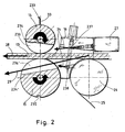
- FIG. 1 indicated cutting device 12 is in Fig. 2 shown clearly in a schematic sectional view.
- the strand machine 10 may also come in operation of the strand machine 10 according to the invention to a strand bursting, so that due to the length of the signal recording after the determination of Strangplatzers about 3 m to 5 m strand are produced, which can fill the space between a measuring nozzle and the format tape uncontrolled. For this reason, it makes sense to let the transport rollers 19 and 20 run permanently or rotate in order to remove the strand material in a targeted manner and to prevent clogging.
- a strand burst can be detected, for example, by an operator, who then initiates a stop of production.
- a sensor 250 'in the region between the position of the strand 13 during the proper production and the Transport rollers 19 and 20 may be provided. This sensor can detect a strand burst relatively quickly.
- a photocell can be used for this purpose.
- a sensor 250 may be arranged below the transport rollers 19, 20. This sensor, which may also be a light barrier, naturally reacts somewhat later than the sensor 250 ', but also relatively early, since in a burst strand relatively quickly material is transported through the transport rollers 19, 20.
- a short-term strand bursting the strand after leaving the cooling web for example, in Fig. 2 is shown with the reference numeral 27, and is up to a measuring nozzle, for example, in the FIGS. 5 and 6 is shown, further transported.
- the strand remains attached to the measuring nozzle and kinks.
- a cover 23 on the strand or over the strand forces the bending of the strand in the direction of the transport rollers 19 and 20.
- the transport roller 19 is preferably spring-loaded, so that multi-layer strand material can be removed.
- the transport rollers detect the strand and promote it via a channel below the transport rollers 19, 20 out of the machine.
- the machine 10 can detect the strand burst over detectors 250, 250 'and is controlled driven into a stop.
- the format belt transports the strand until it kinks out due to the lack of gluing during the controlled stop and from the transport rollers 19, 20 is retracted.
- the transport rollers preferably run at a slight overspeed synchronous to the format band.
- the strand speed is accelerated to, for example, 80 m / min.
- the Strandabschneiderwalzencru or the cutting device 12 separates the strand.
- the cut strand is conveyed straight into the measuring nozzle, according to the strand conveying direction "operation" 28 from Fig. 2 ,
- the separated part of the strand 13 is conveyed away by means of the transport rollers 19 and 20 through a channel of the machine.
- the strand comes open from the format strip 25, the in Fig. 2 is shown.
- the format strip 25 is deflected here via a deflection roller 26.
- the strand 13 is in Fig. 2 but not shown open but closed and in accordance with normal operation of the stranding machine. Due to the open strand, it must be transported through the transport nozzle 16 with the aid of compressed air 24 through the transport nozzle 16, especially here the compressed air nozzles 237 and 238, and the strand cutter or cutting device 12.
- the open strand is drawn in by the transport rollers 19, 20. Further operation corresponds to starting up and commissioning after a controlled stop.
- Cooling web 27 serves to set the adhesive seam on the wrapping material strip.
- Fig. 2 is a schematic sectional view of a part of a stranding machine 10 according to the invention.
- the strand 13 is pulled at startup from the transport rollers 19, 20 at a slight overspeed.
- the strand is closed when reaching the standard speed and has, for example, a speed of max. 80 m / min. reached.
- the speed of the transport rollers 19, 20 is reduced relative to the format strip 25, either at the same speed as the format strip or below this speed.
- the knife roller 14 and the cutting roller 15 are accelerated to strand speed.
- the strand is raised and straightened by the cutting roller 15. After cutting knife rotor 14 and cutting roller 15 are braked within 180 °.
- corresponding recesses 236, 236 'of the rollers 14, 15 are provided, which in Fig. 2 are recognizable as non-hatched areas.
- the strand 13 is detected by the transport rollers 19, 20, wherein the strand 13 is still conveyed in a strand conveying direction "approach" 29.
- the strand 13 is pulled at a slight overspeed compared to the speed of the strand in the format or speed of the format strip 25.
- the strand cutter or cutter 12 accelerates to twice the strand speed and cuts the strand 13 into pieces.
- the knife roller 14 and the cutting roller 15 is rotated in a correspondingly illustrated direction of rotation about the rotation axes 234 and 24 '.
- the cutting edge 233 of the knife 33 comes into operative connection with the strand 13 and dips a little into the groove 235 of the cutting roller 15.
- the filter rods or the excess strand material are detected by the transport rollers 19, 20 and transported away.
- the strand 13, which comes from the cooling web 27 is not kinked.
- the strand is closed and has a speed of about max. 80 m / min.
- the knife rollers 14 and the cutting roller 15 are braked within 180 ° and the proper strand is conveyed in the strand conveying direction "operation" 28.
- FIG. 3 shows a schematic representation of a cutting device according to the invention 12.
- a knife 33 or a knife blade is mounted or mounted on a knife carrier 32 which rotates in a plane inclined to the strand 13, in a direction of rotation, which by ⁇ in Fig. 3 is indicated. Due to the inclined plane, the knife 33 cuts the path of the strand 13 only at one point.
- the strand 13 runs as in Fig. 4 is shown by a downwardly open groove.
- the cutting device 12 can also be arranged so that the groove is not open downwards but to the side or upwards.
- the cutting device 12 according to the invention is shown in a schematic three-dimensional representation.
- the pivot point or the axis of rotation 31 is offset by the dimension A from the strand axis 30, so that when cutting a movement component in the strand conveying direction corresponding to the strand speed is formed.
- This component of motion is indicated by V X.
- the actual movement is indicated by the vector V T.
- the movement component transverse to the strand conveying direction is indicated by V Y.
- a completely burst strand can not be dammed because he can not hit any interference edges.
- the strand 13 can be easily deflected downwards.
- the transport nozzle 16, which in Fig. 2 and in Fig. 1 is shown, can be omitted. The design effort for the cutting device is reduced considerably.
- a cutting edge 34 of the knife 33 is indicated and also an attachment point 46 of the knife 33 on the knife carrier 32.
- the knife carrier can, as in Fig. 3 shown, partially rotationally symmetric, but it can also be a simple lever or arm. In the case of a lever or arm or in the case of FIGS. 3 and 4 In a partially rotationally symmetrical body, it may be useful to compensate for imbalances.
- the lever 37 is pivoted away and the knife 33 is stopped.
- the strand 13 passes through a downwardly open groove 36.
- a strand bursting the strand is deflected downward and can by the transport rollers 19, 20, in the characters 3 to 6 are not shown, but are located in slot 48, are captured.
- the rotational speed of the tension or transport rollers 19, 20 is reduced and the lever 37 is pivoted upwards.
- the servomotor 21 for the knife carrier 32 accelerates in 300 ° to a very high speed, which is adapted to the strand speed with the offset A.
- the cut is made in the following 60 °.
- the motor is decelerated to 300 ° and slowly turned backwards to the starting position.
- FIGS. 5 and 6 a part of a strand machine 10 according to the invention is shown schematically in three dimensions.
- a cutting device 112 is used in another embodiment.
- the axis of rotation of the circular blade 132 is horizontal in operation.
- Fig. 5 the entire cutting device 112, which is arranged on the lever arm 38, pivoted away from the strand 13 upwards.
- the strand 13 is divided into a discharged strand 13 'and a strand 13 "which corresponds to a properly manufactured strand intended for further processing It is, of course, the case that the two strand sections 13' and 13" can not prevail at the same time only as an alternative, both partial strands or strands being shown for illustration purposes.
- the strand 13 ' enters a shaft 48.
- the cutting device 112 pivoted to the strand 13 out.
- the lever arm 38 is moved downward and also the pivot arm 44, which is connected to the cutting device 112, pivots about the pivot axis 43.
- the lever 137 is pivoted about the pivot axis 42 to the strand.
- the pivoting of the cutting device 112 is done via the pivot arm 44 horizontally, so that a safe approach to the strand 13 is made possible to provide an engagement of the knife with the strand.
- the machine 10 comprises a device 11 '(strand material removal device) according to the invention for removing an improper strand section 13 "from the measuring nozzle 40.
- the device 11' has three rollers 51, 52, 53, the rollers 51, 52 a first fork-shaped lever 54 and the roller 53 are arranged on a second lever The axes of the rollers are substantially parallel to each other.
- a sensor 250 can be provided to detect a strand burst and a stop signal to generate, which sets an inventive operating procedure in motion.
- the machine 10 further comprises a different kind of cutting device 112 for severing the strand 13.
- the cutting device 112 essentially consists of a circular blade 132, which may have a corrugated or toothed cutting edge, a lever 137 for supporting the strand 13, and a guide surface 150 for deflecting the strand 13 ', which is not manufactured properly, in particular Fig. 5 down into the slot 48.
- the strand 13 ' is passed into the shaft 48, this can be supported by air nozzles or conveyor rollers, not shown.
- the cutting device 112 is pivoted into the region of the strand 13 ', wherein first the guide surface 150 ensures that the strand 13' does not come into contact with the knife 132.
- the cutting edge of the knife 132 is behind the strand and the lever 137 in front of the strand.
- the lever 137 is moved against the strand 13 'and the knife driven in the opposite direction through the strand, which is severed.
- the proper string 13 "passes through and through its own rigidity to and through the metering nozzle 40.
- the cutter 112 is pivoted back out of the region of the string 13" to reduce the risk of material jamming in front of the metering nozzle in the event of unwanted stranding.
- filter material may pass through the format belt 25 into the gap 151 between the format belt 25 and the transport nozzle 16 (FIG. Fig. 2 ) or a scraper 49 ( Fig. 5, 6 ) is pulled in and there leads to a jam, which would have to be removed manually.
- a blowing air nozzle not shown, may be arranged in the gap in question, which blows through the gap against the direction of travel of the format strip to separate any filter material applied to the format band before it is drawn into the gap.
- FIG. 7a shows a schematic side view of a Strangmaterialab trickvoruze 11 'according to the invention in the pivoted away from the strand 13 position. It can be seen the rollers 52 and 53. The roller 52 is articulated on the lever 54 and thus fixed relative to the lever 54 and the rotation axis 239 or pivot axis 239, however, rotatable.
- a linear actuator 240 is provided to permit pivoting of the strand material delivery device 11 '.
- the linear drive is attached to the lever 54.
- a linear drive 241 is arranged, from which a lever 55 protrudes, which is connected to the roller 53.
- the lever 55 is translationally linearly movable relative to the lever 54, so that as shown below, the relative position of the roller 53 to the rollers 51 and 52 may change.
- Fig. 7a is also schematically illustrated the conveying direction 242 of the strand 13.
- Fig. 7b is the Strandmaterialab consumervoroplasty invention
- Fig. 7a represented in a pivoted to the strand 13 position.
- a corresponding plan view to the representation Fig. 7b is in Fig. 7c shown in schematic representation.
Abstract
Description
Die Erfindung betrifft eine Strangmaterialabfördervorrichtung für eine Strangmaschine der Tabak verarbeitenden Industrie.The invention relates to a Strangmaterialabfördervorrichtung for a strand machine of the tobacco processing industry.
Bei einer Strangmaschine der Tabak verarbeitenden Industrie muss beim Inbetriebnehmen die Geschwindigkeit der Förderung des hergestellten Strangs in einen Normbereich gelangen, um gewünschte Eigenschaften des Strangs wie Festigkeit, Haltbarkeit einer Umhüllungsmaterialnaht und weitere zu erreichen, um den Strang einer normalen Weiterverarbeitung zuzuführen. In dem Moment, wo die entsprechenden Eigenschaften des Strangs erfüllt sind, wird ein Schnitt, ein Bruch bzw. ein Durchtrennen des Strangs vorgenommen und das vor dem Schnitt, dem Bruch bzw. Durchtrennen erzeugte Strangmaterial abgeführt und der darauf folgende Strang der normalen Weiterverarbeitung zugeführt.In an extrusion machine of the tobacco processing industry, the speed of production of the strand produced during commissioning must reach a standard range in order to achieve desired properties of the strand such as strength, durability of a sheath material seam and others to supply the strand with normal further processing. At the moment when the corresponding properties of the strand are met, a cut, a break or a severing of the strand is made and removed before the cut, the break or cutting strand material produced and fed to the subsequent strand of normal processing.
Dies wird üblicherweise dadurch erreicht, dass bei der Wiederinbetriebnahme einer Strangmaschine bis zum Erreichen einer Normgeschwindigkeit und den weiteren gewünschten Eigenschaften des Strangs der hergestellte Strang auf einer anderen Bahn geführt wird als der Strang, der zur Weiterverarbeitung dienen soll.This is usually achieved by the fact that when restarting a strand machine until reaching a standard speed and the other desired properties of the strand of the strand produced on a different path is performed as the strand, which is to serve for further processing.
Hierzu können Führungselemente vorgesehen sein, wie beispielsweise in der
Im Betrieb einer Strangmaschine kann es auch geschehen, dass aufgrund eines Fehlers der Strang nach Verlassen einer Formatvorrichtung, in der der Strang gebildet wird und in dem beispielsweise ein Umhüllungsmaterialstreifen um diesen gewickelt wird und an einer Klebenaht verschlossen wird, aufplatzt, so dass der Raum stromabwärts der Formatvorrichtung sehr schnell verstopfen kann. Dieses Material muss dann manuell entfernt werden.In the operation of a stranding machine it can also happen that, due to a defect, the strand breaks up after leaving a formatting device in which the strand is formed and in which, for example, a wrapping material strip is wrapped around it and closed at an adhesive seam, so that the space downstream the format device can clog very quickly. This material must then be removed manually.
Es ist Aufgabe der vorliegenden Erfindung, Komponenten einer Strangmaschine der Tabak verarbeitenden Industrie fortzubilden, die für einen sicheren Betrieb der Strangmaschine dienen sollen. Es soll ferner eine Strangmaterialabfördervorrichtung angegeben werden, mittels der die Wiederinbetriebnahme einer Strangmaschine ermöglicht ist und bei Auftreten eines Fehlers in der Strangmaschine das nicht zur Weiterverarbeitung vorgesehene Strangmaterial effizient abgefördert werden kann.It is an object of the present invention to further develop components of a rod making machine of the tobacco processing industry, which are to serve for safe operation of the stranding machine. It is also intended to specify a strand material removal device by means of which the restarting of a stranding machine is made possible and when an error in the stranding machine, not intended for further processing strand material can be efficiently removed.
Die Aufgabe wird durch eine Strangmaterialabfördervorrichtung umfassend eine erste Hebelvorrichtung und eine zweite Hebelvorrichtung gelöst, wobei eine Hebelvorrichtung relativ zur anderen Hebelvorrichtung translatorisch bewegbar ist. Insbesondere ist eine translatorische lineare Bewegung relativ zueinander vorgesehen. Vorzugsweise sind die erste und die zweite Hebelvorrichtung um eine gemeinsame Schwenkachse, die insbesondere im Wesentlichen parallel zu einer Strangförderrichtung ist, verschwenkbar. In diesem Fall kann die Strangmaterialabfördervorrichtung in den Wirkbereich mit einem Strang bzw. einem Strangstück, das abzufördern ist, verschwenkt werden, um anschließend mit einer translatorischen, insbesondere linearen Bewegung, eine Hebelvorrichtung anschließend den Strang zu greifen und beispielsweise aus Bereichen herauszuziehen, in denen der Strang noch steckt. Nach Freigeben des Strangs kann dieser dann beispielsweise in einen Behälter abgeführt werden. Diesbezüglich sei insbesondere auf die Figurenbeschreibung zu den
Vorzugsweise weist die zweite Hebelvorrichtung zwei Arme auf. Insbesondere vorzugsweise ist die erste Hebelvorrichtung wenigstens teilweise zwischen den Armen der zweiten Hebelvorrichtung angeordnet. Wenn die erste und/oder zweite Hebelvorrichtung eine Rolle umfasst, die in Eingriff mit dem Strangmaterial bringbar ist, kann dieses sehr sicher aus Öffnungen, in denen der Strang noch stecken kann, herausgezogen werden, ohne vorher zu zerreißen bzw. gebrochen zu werden. Durch diese Maßnahme ist eine Automatisierung des Strangmaterialabförderns sehr einfach möglich.Preferably, the second lever device has two arms. Particularly preferably, the first lever device is at least partially disposed between the arms of the second lever device. If the first and / or second lever device comprises a roller which can be brought into engagement with the strand material, it can be very safely pulled out of openings in which the strand can still be stuck without first being torn or broken. By this measure, an automation of Strangmaterialabförderns is very easy.
Erfindungsgemäß ist eine Strangmaschine der Tabak verarbeitenden Industrie mit einer Schneidvorrichtung und einer Strangmaterialabfördervorrichtung, die vorstehend beschrieben wurde, versehen.According to the invention, a tobacco industry rod maker is provided with a cutter and a strand material delivery device as described above.
Eine bevorzugte Strangdurchschneidvorrichtung der Tabak verarbeitenden Industrie zeichnet sich durch einen rotierend bewegten Schneidkörper mit einer Schneidkante aus, wobei der Schneidkörper auf einem ersten Rotationskörper mit einer Rotationsachse angeordnet ist, wobei der Schneidkörper im Wesentlichen parallel zur Rotationsachse des ersten Rotationskörpers angeordnet ist, und wobei der Schneidkörper eine Ausdehnung wenigstens von einem Befestigungspunkt zu einer Schneidkante aufweist, wobei sich durch die Ausdehnung eine Tangente des ersten Rotationskörpers oder eine Parallele hierzu erstreckt.A preferred strand cutting device of the tobacco processing industry is characterized by a rotating cutting body with a cutting edge, wherein the cutting body is disposed on a first body of revolution having a rotation axis, wherein the cutting body is arranged substantially parallel to the axis of rotation of the first body of revolution, and wherein the cutting body an extension at least from an attachment point to a cutting edge, wherein the extension extends a tangent of the first body of revolution or a parallel thereto.
Durch die Anordnung des Schneidkörpers im Wesentlichen parallel zur Rotationsachse eines ersten Rotationskörpers kann ein sehr effizienter und genauer Schnitt durch einen Strang der Tabak verarbeitenden Industrie durchgeführt werden. Unter erstem Rotationskörper ist im Rahmen dieser Erfindung insbesondere ein rotierender Körper zu verstehen, der eine Rotationssymmetrie aufweisen kann, diese aber nicht aufweisen muss. So kann beispielsweise auch ein Teilzylinder vorgesehen sein oder ein Kegel bzw. ein Teilkegel oder einfach nur ein Arm, an dessen äußerem Ende der Schneidkörper tangential oder parallel hierzu oder im Wesentlichen parallel zur Rotationsachse des ersten Rotationskörpers angeordnet ist, also beispielsweise nicht ganz am Ende des Armes sondern radial versetzt hierzu, wobei unter tangential angeordnet bzw. parallel zur tangentialen Anordnung insbesondere eine an dem ersten Rotationskörper tatsächlich vorherrschende Tangente gemeint ist oder aber eine Tangente gemeint ist, die an einem durch Rotation erzeugten Kreis anliegen kann.Due to the arrangement of the cutting body substantially parallel to the axis of rotation of a first rotating body, a very efficient and accurate cutting can be performed by a strand of the tobacco processing industry. In the context of this invention, the term first rotary body is to be understood in particular to mean a rotating body which may have rotational symmetry but need not have it. Thus, for example, a partial cylinder may be provided or a cone or a partial cone or just an arm, at the outer end of the cutting body is arranged tangentially or parallel thereto or substantially parallel to the axis of rotation of the first body of revolution, so for example not quite at the end of Poor but radially offset thereto, being tangentially arranged or meant parallel to the tangential arrangement, in particular a tangent on the first body of revolution actually predominant tangent or a tangent is meant that on a circle generated by rotation can be present.
Die Tangente oder die Parallele zur Tangente verläuft also vorzugsweise durch einen Befestigungspunkt des Schneidkörpers zu einer Schneidkante, oder aber eine Parallele zur Tangente verläuft durch die Ausdehnung des Schneidkörpers. Besonders bevorzugt ist eine Ausführungsform, in der der Schneidkörper wenigstens teilweise in längsaxialer Richtung der Drehachse über den ersten Rotationskörper hinausragt. Hierbei ist die Schneidkante von dem ersten Rotationskörper beabstandet bzw. zu dem Rotationskörper beabstandet, beispielsweise unterhalb oder oberhalb des ersten Rotationskörpers relativ zur axialen Richtung der Drehachse gesehen. Die Schneidkante wird vorzugsweise bei der Rotation des ersten Rotationskörpers senkrecht zur Drehachse bewegt. Der Schneidkörper und die Schneidkante ragen vorzugsweise über den Bereich des ersten Rotationskörpers hinaus, der benachbart zu der Mantelfläche ist bzw. an die Mantelfläche angrenzt. Der Schneidkörper ragt also über die Endflächen des ersten Rotationskörpers hinaus. Unter Strangdurchschneidvorrichtung ist im Rahmen der Erfindung auch eine Strangtrennvorrichtung bzw. Strangdurchtrennvorrichtung zu verstehen.The tangent or the parallel to the tangent thus preferably extends through an attachment point of the cutting body to a cutting edge, or a parallel to the tangent extends through the extension of the cutting body. Particularly preferred is an embodiment in which the cutting body protrudes at least partially in the longitudinal axial direction of the axis of rotation beyond the first rotary body. Here, the cutting edge of the first rotary body is spaced or spaced from the rotational body, for example, seen below or above the first rotary body relative to the axial direction of the axis of rotation. The cutting edge is preferably moved perpendicular to the rotation axis during the rotation of the first rotation body. The cutting body and the cutting edge preferably project beyond the region of the first rotation body, which is adjacent to the lateral surface or adjoins the lateral surface. The cutting body thus protrudes beyond the end surfaces of the first rotation body. Under strand cutting device is to be understood in the context of the invention, a strand separation device or strand cutting device.
Vorzugsweise ist die Schneidkante im Wesentlichen parallel zur Drehachse des ersten Rotationskörpers angeordnet. Die Schneidkante kann allerdings auch schräg hierzu angeordnet sein oder es kann eine angeschrägte Schneidkante vorgesehen sein. Die Schneidkante ist quer, vorzugsweise senkrecht zur Tangente oder Parallelen hierzu, die durch die Ausdehnung des Schneidkörpers verläuft, angeordnet.Preferably, the cutting edge is arranged substantially parallel to the rotation axis of the first rotation body. However, the cutting edge can also be arranged obliquely thereto or it can be provided a bevelled cutting edge. The cutting edge is transversely, preferably perpendicular to the tangent or parallels thereto, which extends through the extension of the cutting body arranged.
Wenn die Drehachse des ersten Rotationskörpers beabstandet zu einer Längsachse eines zu schneidenden Strangs ist, also gegenüber der Längsachse versetzt ist, kann ein Schnitt mit minimaler oder keiner Stauchung eines sich bewegenden Strangs quer zur Bewegungsrichtung des Strangs erzielt werden.If the axis of rotation of the first body of revolution is spaced from a longitudinal axis of a strand to be cut, ie opposite the longitudinal axis is offset, a cut can be achieved with minimal or no compression of a moving strand transverse to the direction of movement of the strand.
Vorzugsweise ist die Drehachse des ersten Rotationskörpers in einem Winkel zur Längsachse eines zu schneidenden Strangs angeordnet, der ungleich 90° ist. Der Winkel ist zwischen der Drehachse bzw. einer Projektion der Drehachse auf die Längsachse zu messen bzw. angegeben, da die Drehachse und die Längsachse sich nicht notwendigerweise schneiden müssen. Der Winkel entspricht einem Winkel, der durch eine entsprechende parallele Verschiebung der Drehachse oder der Längsachse sich zwischen den beiden Achsen ergibt. Vorzugsweise ist der Winkel zwischen der Drehachse des ersten Rotationskörpers und der Längsachse im stromabwärtigen Teil des Strangs kleiner 90°. Dieser Winkel ist vorzugsweise in Abhängigkeit der Geschwindigkeit des Strangs und insbesondere des Abstand der Drehachse zur Längsachse einstellbar, um einen möglichst sauberen Schnitt ohne Stauchung des Strangs zu ermöglichen.Preferably, the axis of rotation of the first body of revolution is arranged at an angle to the longitudinal axis of a strand to be cut, which is not equal to 90 °. The angle is to be measured or indicated between the axis of rotation or a projection of the axis of rotation on the longitudinal axis, since the axis of rotation and the longitudinal axis need not necessarily intersect. The angle corresponds to an angle that results from a corresponding parallel displacement of the axis of rotation or the longitudinal axis between the two axes. Preferably, the angle between the axis of rotation of the first body of revolution and the longitudinal axis in the downstream part of the strand is less than 90 °. This angle is preferably adjustable as a function of the speed of the strand and in particular the distance of the axis of rotation to the longitudinal axis in order to allow the cleanest possible cut without compression of the strand.
Besonders bevorzugt ist es, wenn eine Nut zur Führung eines Strangs vorgesehen ist, die zum einen für einen sauberen Schnitt sorgt und zum anderen für eine gute Führung des Strangs. Die Nut erstreckt sich längsaxial zum Strang bzw. kann auch die Längsachse des Strangs zumindest im Bereich der Schneidvorrichtung definieren.It is particularly preferred if a groove for guiding a strand is provided which on the one hand ensures a clean cut and on the other hand for a good guidance of the strand. The groove extends longitudinally to the strand or can also define the longitudinal axis of the strand at least in the region of the cutting device.
Es ist ferner vorzugsweise eine kreisabschnittsförmige Nut oder Öffnung vorgesehen, die eine Hindurchbewegung des über den ersten Rotationskörper hinausragenden Teils des Schneidkörpers ermöglicht.It is further preferably provided a circular-section-shaped groove or opening, which allows a passage of the projecting beyond the first rotary body portion of the cutting body.
Eine bevorzugte Strangdurchschneidvorrichtung der Tabak verarbeitenden Industrie ist mit einem rotierend bewegten Schneidkörper versehen, der ein Messer aufweist, wobei die Schneidkante des Messers parallel zur Rotationsachse des Schneidkörpers angeordnet ist. Vorzugsweise ist die Schneidkante wenigstens doppelt so lang wie der Durchmesser des durchzuschneidenden bzw. durchzutrennenden Strangs. Vorzugsweise erstreckt sich das Messer senkrecht zur Rotationsachse über den Schneidkörper. Hierdurch können sehr präzise Schnitte ausgeführt werden. Vorzugsweise ist der Schneidkörper ein Rotationskörper oder ein Teil eines Rotationskörpers.A preferred strand cutting device of the tobacco processing industry is provided with a rotating moving cutting body having a knife, wherein the cutting edge of the knife is arranged parallel to the axis of rotation of the cutting body. Preferably, the cutting edge is at least twice as long as the diameter of the strand to be cut or severed. Preferably, the knife extends perpendicular to the axis of rotation about the cutting body. As a result, very precise cuts can be performed. Preferably, the cutting body is a rotary body or a part of a rotary body.
Besonders effizient ist die Strangdurchschneidvorrichtung dann, wenn eine Schneidwalze vorgesehen ist, die mit dem Schneidkörper zusammenwirkt. Hierzu ist vorzugsweise eine Nut in der Schneidwalze vorgesehen, in die das Messer im Betrieb zeitweise eintaucht. Vorzugsweise weist der Schneidkörper und/oder die Schneidwalze eine Aussparung oder eine Abflachung auf. Eine Aussparung ist im Rahmen der Erfindung insbesondere ein sich über eine gewisse Länge parallel zur Rotationsachse erstreckender Einschnitt im Rotationskörper, so dass sich dort ein Freiraum im Rotationskörper ergibt. Eine Abflachung ist im Rahmen der Erfindung insbesondere ein Rotationskörper, von dem Material entfernt wurde. Bei einem zylinderförmigen Rotationskörper ist beispielsweise dann ein Zylinderabschnitt entfernt. Bei einem Schnitt durch den Rotationskörper wäre dann ein Teilkreisabschnitt entfernt.The strand cutting device is particularly efficient when a cutting roller is provided which cooperates with the cutting body. For this purpose, a groove is preferably provided in the cutting roller, in which the knife dips during operation temporarily. Preferably, the cutting body and / or the cutting roller has a recess or a flattening. In the context of the invention, a cutout is, in particular, a cut extending in the rotation body over a certain length parallel to the axis of rotation, so that there is a free space in the rotation body. A flattening is in the context of the invention, in particular a rotating body, was removed from the material. In a cylindrical rotary body, for example, a cylinder section is then removed. In a section through the rotary body then a partial circle section would be removed.
Im Betrieb dienen die Aussparung und/oder die Abflachung dazu, für das Strangmaterial ausreichend Raum zu lassen, damit dieses von der Strangdurchschneidvorrichtung und insbesondere dem Schneidkörper und der Schneidwalze ungehindert hindurchtreten kann bzw. gefördert werden kann. Dieses gilt zum einen im Betrieb, wenn der gebildete Strang zur Weiterverarbeitung benutzt werden soll, als auch beim Anfahren, bei dem beispielsweise das Strangmaterial auf einer anderen Bahn geführt wird.In operation, the recess and / or the flattening serve to leave sufficient space for the strand material, so that it can pass unhindered by the strand cutting device and in particular the cutting body and the cutting roller or can be promoted. This applies on the one hand in operation, if the strand formed is to be used for further processing, as well as when starting, in which, for example, the strand material is guided on another track.
Wenn wenigstens eine Druckluftdüse vorgesehen ist, die ausgebildet ist, um Druckluft im Betrieb gegen den Strang zu richten, kann das Anfahren der Strangproduktion und die Überführung der Strangförderrichtung von dem Anfahren in die endgültige Produktion unterstützt werden. Hierbei kann beispielsweise eine Druckluftdüse vorgesehen sein, die oberhalb vom Strang angeordnet ist und in Strangförderrichtung sowie ein wenig abwärts gerichtet ist. Es kann ferner eine Druckluftdüse vorgesehen sein, die unterhalb vom Strang angeordnet ist und Druckluft in Strangförderrichtung und ein wenig aufwärts ausgerichtet ist. Je nach gewünschter Stranglage können die obere oder die untere oder beide Druckluftdüsen betrieben werden.If at least one compressed air nozzle is provided, which is designed to direct compressed air against the strand during operation, the start of the strand production and the transfer of the strand conveying direction from the start into the final production can be assisted. Here, for example, a compressed air nozzle may be provided, which is arranged above the strand and is directed in the strand conveying direction and a little downwards. It can also be provided a compressed air nozzle, which is arranged below the strand and compressed air in the strand conveying direction and a little bit upwards. Depending on the desired strand position, the upper or the lower or both compressed air nozzles can be operated.
Vorzugsweise ist ferner eine Strangdurchschneidvorrichtung mit einem rotierend bewegbaren Schneidkörper mit einer Schneidkante vorgesehen, wobei der Schneidkörper um eine Rotationsachse bewegbar ist, die quer zu einem vom Schneidkörper durchschneidbaren Strang liegt, wobei die Rotationsachse im Betrieb der Strangdurchschneidvorrichtung im Wesentlichen horizontal angeordnet ist. Vorzugsweise ist der Schneidkörper um eine Rotationsachse bewegbar, die im Wesentlichen senkrecht zu einem vom Schneidkörper durchschneidbaren Strang liegt. Vorzugsweise ist der Schneidkörper vom Strang wegschwenkbar. Wegschwenkbar bedeutet im Rahmen der Erfindung insbesondere aus dem Wirkbereich mit dem Strang schwenkbar.Preferably, a strand cutting device is provided with a rotating movable cutting body with a cutting edge, wherein the cutting body is movable about an axis of rotation which is transverse to a cutting body cut by the cutting body, wherein the axis of rotation is arranged substantially horizontally in the operation of the strand cutting device. Preferably, the cutting body is movable about an axis of rotation which is substantially perpendicular to a strand which can be cut by the cutting body. Preferably, the cutting body is pivotable away from the strand. Wegschwenkbar means within the scope of the invention in particular from the effective range with the strand pivotally.
Vorzugsweise ist eine Strangführung vorgesehen, die baulich mit dem Schneidkörper angeordnet ist, so dass diese um eine gemeinsame Schwenkachse von dem Strang wegschwenkbar sind. Die Strangführung und der Schneidkörper sind beispielsweise so ausgestaltet, dass die Rotationsachse des Schneidkörpers und eine Strangführungsfläche im Wesentlichen parallel zueinander sind.Preferably, a strand guide is provided, which is structurally arranged with the cutting body, so that these around a common Swivel axis are pivoted away from the strand. The strand guide and the cutting body are configured, for example, such that the axis of rotation of the cutting body and a strand guide surface are substantially parallel to one another.
Die Schwenkachse ist vorzugsweise im Wesentlichen parallel zu dem hergestellten Strang angeordnet. Im Unterschied zur
Vorzugsweise ist stromaufwärts der Schneidvorrichtung ein Gegenhalter angeordnet, der das Strangdurchschneiden unterstützt. Der Gegenhalter kann eine Art Abschläger sein. Der Gegenhalter kann eine geringe Voreilung beim Heranfahren an den Strang erfahren, so dass er bereits in der für einen Trennschnitt erforderlichen Gegenhaltelage hat, wenn der Schneidkörper mit seinem Schneidmesser auf den Strang einwirkt. Der Gegenhalter ist im Gegensatz zur
Eine bevorzugte weitere Strangmaterialabfördervorrichtung für eine Strangmaschine der Tabak verarbeitenden Industrie weist zwei gegenläufig drehende zweite Rotationskörper auf, wobei mittels der zweiten Rotationskörper Strangmaterial zwischen den zweiten Rotationskörpern einziehbar und anschließend abförderbar ist, wobei ein sich zwischen den zweiten Rotationskörpern bildender Spalt sich im Wesentlichen in Förderrichtung eines Strangs im Produktionsbetrieb erstreckt. Unter Produktionsbetrieb wird im Rahmen der Erfindung insbesondere die Produktion oder Herstellung eines Strangs in der vorgebbaren Normgeschwindigkeit bzw. eines ordnungsgemäßen Strangs, der zur Weiterverarbeitung gefördert werden kann, verstanden.A preferred further Strangmaterialabfördervorrichtung for a strand machine of the tobacco-processing industry has two counter-rotating second rotation body, wherein by means of the second rotation body strand material between the second bodies of rotation retractable and then abförderbar, wherein a forming between the second bodies of revolution gap substantially in the conveying direction of a Strangs in the production plant extends. Under production operation is within the scope of the invention in particular, the production or production of a strand in the predetermined standard speed or a proper strand, which can be promoted for further processing understood.
Die zweiten Rotationskörper sind vorzugsweise ein wenig beabstandet, um ausreichend Strangmaterial durch die Lücke der zweiten Rotationskörper abführen zu können. Die Drehrichtung der zweiten Rotationskörper ist derart, dass die Drehkomponente des jeweiligen zweiten Rotationskörpers an der zum anderen zweiten Rotationskörper nächstliegenden Stelle in die gleiche Richtung zeigt, und zwar weg von dem Raum, aus dem Strangmaterial abzuführen ist. Vorzugsweise sind die Rotationsachsen der zweiten Rotationskörper im Wesentlichen parallel. Die zweiten Rotationskörper sind vorzugsweise zylinderförmig. Diese können allerdings auch kegelförmig sein oder jeweils einen Arm oder mehrere Arme aufweisen. Die zweiten Rotationskörper können auch im Querschnitt sternförmig sein oder eine geometrische Figur darstellen, die nicht kreisförmig im Querschnitt ist. Im Falle von einer Kegel- bzw. Kegelstumpfform kann es Sinn machen, die Rotationsachsen der zweiten Rotationskörper nicht parallel anzuordnen, und zwar derart, dass die Tangentialflächen der Linien der jeweiligen Mantelfläche der zweiten Rotationskörper an der Stelle, wo diese sich am nächsten kommen, parallel zueinander sind, so dass sich insbesondere ein gerader Schlitz bildet.The second rotation bodies are preferably a little bit spaced in order to be able to discharge sufficient strand material through the gap of the second rotation body. The rotational direction of the second rotational body is such that the rotational component of the respective second rotational body faces the closest to the other second rotational body in the same direction, away from the space from which strand material is to be dissipated. Preferably, the axes of rotation of the second rotating body are substantially parallel. The second rotation bodies are preferably cylindrical. However, these can also be conical or each have one arm or more arms. The second bodies of revolution can also be star-shaped in cross-section or represent a geometric figure which is not circular in cross-section. In the case of a conical or truncated cone shape, it may make sense not to arrange the axes of rotation of the second rotary body parallel, in such a way that the tangential surfaces of the lines of the respective lateral surface of the second rotary body at the point where they come closest, parallel to each other, so that in particular forms a straight slot.
Vorzugsweise sind die Rotationsachsen der zweiten Rotationskörper quer zur Förderrichtung eines Strangs angeordnet. Quer bedeutet im Rahmen der Erfindung, dass der Spalt in einem Winkel von > 0° bis 40° vom Strang weg orientiert ist, wobei der Strang und der Spalt in einer Ebene angeordnet sind. Der durch die zweiten Rotationskörper gebildete Schlitz bzw. Spalt bildet eine Linie, die vorzugsweise eine Komponente aufweist, die parallel zur Förderrichtung des Strangs angeordnet ist.Preferably, the axes of rotation of the second rotary body are arranged transversely to the conveying direction of a strand. Cross means in the context of the invention that the gap is oriented at an angle of> 0 ° to 40 ° away from the strand, wherein the strand and the gap are arranged in a plane. The slot formed by the second rotary bodies forms a line, preferably a component which is arranged parallel to the conveying direction of the strand.
Vorzugsweise sind die zweiten Rotationskörper relativ zueinander druckbelastet bzw. kraftbelastet. Hierdurch können unterschiedliche Mengen Filtermaterial ohne Probleme abgefördert werden. Vorzugsweise ist ein erster zweiter Rotationskörper gegen einen zweiten zweiten Rotationskörper federbelastet. Unter federbelastet wird im Rahmen der Erfindung verstanden, dass der erste zweite Rotationskörper mit einer Feder vorgespannt ist, dergestalt, dass der erste zweite Rotationskörper gegen den zweiten zweiten Rotationskörper drückt. Hierzu ist der erste zweite Rotationskörper in queraxialer Richtung beweglich ausgebildet. Vorzugsweise sind beide zweiten Rotationskörper mit Federn vorgespannt und beide entsprechend in queraxialer Richtung beweglich.Preferably, the second rotating bodies are pressure-loaded or force-loaded relative to one another. As a result, different amounts of filter material can be carried away without problems. Preferably, a first second rotary body is spring-loaded against a second second rotary body. In the context of the invention, spring-loaded means that the first second rotary body is biased by a spring, such that the first second rotary body presses against the second second rotary body. For this purpose, the first second rotary body is designed to be movable in the transverse-axial direction. Preferably, both second rotary body are biased by springs and both movable accordingly in the transverse axial direction.
Vorzugsweise ist ein zweiter Rotationskörper eine Transportwalze und besonders bevorzugt sind beide zweite Rotationskörper jeweils Transportwalzen. Anstelle von Transportwalzen können auch Kegel, Hebel, einarmige, zweiarmige, dreiarmige bis n-armige (n ganzzahlig) Rotationskörper bzw. Vorrichtungen vorgesehen sein, die zum Transport von Material geeignet sind. Für den Fall, dass die zweiten Rotationskörper keine Rotationskörper im mathematischen Sinne sind, sondern rotierende Körper mit Armen, die sich radial erstrecken, kann vorgesehen sein, dass die zwei zweiten Rotationskörper derart zusammenwirken, dass die Arme an der Mantelfläche bzw. an der außenliegenden Fläche miteinander zusammenwirken. Die Arme können allerdings auch ineinander eingreifen, wenn beispielsweise das Filtermaterial gleichzeitig mit der Abförderung auch zerkleinert werden soll. Die zweiten Rotationskörper können beispielsweise auch sternförmig ausgebildet sein. Vorzugsweise sind die Rotationskörper symmetrisch ausgebildet. Es können bei den zweiten Rotationskörpern auch Vertiefungen und Erhöhungen im Umfang bzw. in der Mantelfläche vorgesehen sein, die die Funktionalität des Transports verbessern.Preferably, a second rotary body is a transport roller and particularly preferably both second rotary bodies are respective transport rollers. Instead of transport rollers and cones, levers, one-armed, two-armed, three-armed to n-arm (n integer) rotation body or devices may be provided which are suitable for the transport of material. In the event that the second rotary bodies are not rotary bodies in the mathematical sense, but rotating bodies with arms which extend radially, it can be provided that the two second rotary bodies cooperate such that the arms on the lateral surface or on the outer surface interact with each other. However, the arms can also intermesh, for example, if the filter material is to be crushed simultaneously with the discharge. The second rotation body may for example also be formed star-shaped. Preferably, the rotational bodies are formed symmetrically. It can in the second bodies of revolution Also depressions and elevations in the circumference or in the lateral surface may be provided, which improve the functionality of the transport.
Wenn vorzugsweise eine Strangmaterialleitvorrichtung stromaufwärts oder im Bereich der zweiten Rotationskörper vorgesehen ist, ist gewährleistet, dass das Strangmaterial auch vollständig abgefördert werden kann. Bei einer Strangmaterialleitvorrichtung kann es sich beispielsweise um eine Abdeckung handeln, die das Material in eine gewünschte Richtung ablenkt.If preferably a strand material guiding device is provided upstream or in the region of the second rotation body, it is ensured that the strand material can also be completely conveyed away. For example, a strand material guide may be a cover that deflects the material in a desired direction.
Es ist ein bevorzugtes Verfahren zum Betrieb einer Strangmaschine der Tabak verarbeitenden Industrie dadurch angegeben, dass für die Produktion eines Strangs zunächst ein Strang gebildet und gefördert wird und in dem Fall, dass die Produktion unterbrochen wird, wobei das Unterbrechen durch eine Bedienperson oder einen Sensor ausgelöst wird, das in der Strangmaschine verbliebene Material automatisch aus der Strangmaschine entfernt wird und anschließend die Produktion neu gestartet wird. Durch diese Verfahrensführung kann bei einer Produktionsunterbrechung effizient und automatisch die Strangproduktion wieder gestartet werden, wobei Fehlproduktionen von Strangmaterial vermieden werden. Vorzugsweise wird nach dem Start der Produktion der Anfahrschuss abgetrennt und anschließend der Strang den weiteren Verarbeitungsschritten zugeführt. Mit dem anschließenden Zuführen des Strangs zu den weiteren Verarbeitungsschritten ist insbesondere die Gut-Produktion gemeint, also ein Strang mit vorgebbaren Eigenschaften und/oder ein Strang, der eine Sollgeschwindigkeit erreicht hat. Vorzugsweise wird für den Fall, dass der Strang sich öffnet, das Strangmaterial über zwei zweite Rotationskörper abgefördert wird, wobei die zweiten Rotationskörper das Strangmaterial in einem sich zwischen den zweiten Rotationskörpern bildenden Spalt hindurchfördern. Die Rotationskörper drehen sich bzw. rotieren, um das Strangmaterial entsprechend effizient abzufördern.A preferred method of operating an extrusion machine of the tobacco processing industry is characterized in that a strand is first formed and conveyed for the production of a strand, and in the event that production is interrupted, the interruption is initiated by an operator or a sensor is that the remaining material in the stranding machine is automatically removed from the stranding machine and then the production is restarted. As a result of this process management, strand production can be restarted efficiently and automatically in the event of a production stoppage, whereby defective production of strand material is avoided. Preferably, after the start of production, the starting shot is separated and then the strand is fed to the further processing steps. With the subsequent feeding of the strand to the further processing steps in particular the good-production is meant, ie a strand with predetermined properties and / or a strand which has reached a target speed. Preferably, in the event that the strand opens, the strand material is conveyed away via two second rotation body, wherein the second rotation body convey the strand material in a gap forming between the second rotation bodies. The rotation body rotate or rotate to promote the strand material accordingly efficient.
Vorzugsweise geschieht das Entfernen des Strangmaterials mittels Hebelvorrichtungen, mittels der das Strangmaterial erfasst und bewegt und anschließend wieder freigegeben wird. Hierbei wird insbesondere Strangmaterial aus Öffnungen herausgezogen, was sonst zu Fehlproduktionen beim Starten der Produktion führen würde.Preferably, the removal of the strand material by means of lever devices, by means of which the strand material is detected and moved and then released again. Here, in particular strand material is pulled out of openings, which would otherwise lead to faulty production when starting production.
Ein weiteres bevorzugtes Verfahren zum Betrieb einer Strangmaschine der Tabak verarbeitenden Industrie ist dadurch angegeben, dass Strangmaterial zwischen einem sich durch zwei zweite Rotationskörpern bildenden Spalt hindurch abgefördert wird, wobei stromaufwärts der zweiten Rotationskörper ein Strang gebildet wird und nach dem Bilden stromaufwärts der zweiten Rotationskörper zerschnitten wird, sobald ein Strang mit vorgebbaren Eigenschaften hergestellt wird oder eine Sollgeschwindigkeit erreicht wird, und wobei der relativ zur Schnittstelle stromabwärtige Abschnitt des Strangs abgefördert wird und der relativ zur Schnittstelle stromaufwärtige Teil des Strangs zur Weiterbearbeitung an den zweiten Rotationskörpern vorbeigeführt wird. Dieses Verfahren eignet sich besonders zum Wiederanfahren oder Inbetriebnehmen einer entsprechenden Strangmaschine der Tabak verarbeitenden Industrie.Another preferred method of operating a rod making machine of the tobacco processing industry is characterized by discharging strand material between a nip constituting two second bodies of revolution, forming a strand upstream of the second body of revolution, and cutting the second body of revolution upstream after forming as soon as a strand is produced with predetermined properties or a target speed is reached, and wherein the relative to the interface downstream portion of the strand is carried away and the upstream relative to the interface part of the strand for further processing to the second bodies of revolution is passed. This method is particularly suitable for restarting or commissioning a corresponding strand machine of the tobacco processing industry.
Vorzugsweise ist die Rotationsgeschwindigkeit der zweiten Rotationskörper wenigstens zeitweise größer als die Fördergeschwindigkeit des Strangs bei dem Herstellen des Strangs. Das Strangmaterial wird somit etwas schneller abgeführt als der Strang gebildet wird. Die Rotationsgeschwindigkeit der zweiten Rotationskörper ist vorzugsweise größer als die Geschwindigkeit eines Formatbandes, in dem der Strang gebildet wird. Vorzugsweise ist die höhere Geschwindigkeit solange vorgesehen, wie wenigstens eine vorgebbare Eigenschaft des Strangs nicht vorliegt oder eine vorgebbare Strangfördergeschwindigkeit nicht erreicht ist. Ab Erreichen einer vorgebbaren Strangfördergeschwindigkeit bzw. ab Erreichen der gewünschten Eigenschaften kann die Geschwindigkeit der zweiten Rotationskörper auf die Fördergeschwindigkeit des Strangs angepasst werden.Preferably, the rotational speed of the second rotational body is at least temporarily greater than the conveying speed of the strand in the production of the strand. The strand material is thus dissipated a little faster than the strand is formed. The rotational speed of the second rotary body is preferably greater than the speed of a format strip in which the strand is formed. Preferably, the higher speed provided as long as at least one predetermined property of the strand does not exist or a predetermined strand conveying speed is not reached. From reaching a predetermined strand conveying speed or from reaching the desired properties, the speed of the second rotating body can be adapted to the conveying speed of the strand.
Die Erfindung wird nachstehend ohne Beschränkung des allgemeinen Erfindungsgedankens anhand von Ausführungsbeispielen unter Bezugnahme auf die Zeichnungen beschrieben. Bezüglich aller im Text nicht näher erläuterten erfindungsgemäßen Einzelheiten wird ausdrücklich auf die Zeichnungen verwiesen. Es zeigen:
- Fig. 1
- eine schematische dreidimensionale Darstellung eines Teils einer Strangmaschine der Tabak verarbeitenden Industrie,
- Fig. 2
- eine schematische Schnittdarstellung eines Teils des Ausführungsbeispiels aus
Fig. 1 in Seitenansicht, - Fig. 3
- eine schematische Darstellung einer Schneidvorrichtung,
- Fig. 4
- eine schematische dreidimensionale Darstellung der Schneidvorrichtung aus
Fig. 3 , - Fig. 5
- einen Teil einer Ausführungsform einer erfindungsgemäßen Strangmaschine der Tabak verarbeitenden Industrie in schematischer Darstellung,
- Fig. 6
- den Teil aus
Fig. 5 aus einer anderen Perspektive und in einem anderen Verfahrenszustand in schematischer Darstellung, - Fig. 7a
- eine erfindungsgemäße Strangmaterialabfördervorrichtung in schematischer Seitenansicht in weggeschwenkter Position,
- Fig. 7b
- die Vorrichtung aus
Fig. 7a in einer zum Strang geschwenkten Position, - Fig. 7c
- die
Fig. 7b in einer schematischen Draufsicht, - Fig. 7d
- die erfindungsgemäße Strangmaterialabfördervorrichtung in einem Schritt des Strangmaterialherausziehens in schematischer Seitenansicht, und
- Fig. 7e
- eine schematische Draufsicht auf die Vorrichtung gemäß
Fig. 7d
- Fig. 1
- a schematic three-dimensional representation of a part of a strand machine of the tobacco-processing industry,
- Fig. 2
- a schematic sectional view of a portion of the embodiment of
Fig. 1 in side view, - Fig. 3
- a schematic representation of a cutting device,
- Fig. 4
- a schematic three-dimensional representation of the cutting device
Fig. 3 . - Fig. 5
- a schematic representation of a part of an embodiment of a tobacco processing machine according to the invention,
- Fig. 6
- the part out
Fig. 5 from a different perspective and in a different process state in a schematic representation, - Fig. 7a
- a Strangmaterialabfördervorrichtung invention in a schematic side view in weggeschwenkter position,
- Fig. 7b
- the device off
Fig. 7a in a position pivoted to the strand, - Fig. 7c
- the
Fig. 7b in a schematic plan view, - Fig. 7d
- the Strangmaterialabfördervorrichtung invention in a step of Strangmaterialausziehens in a schematic side view, and
- Fig. 7e
- a schematic plan view of the device according to
Fig. 7d
In den folgenden Figuren sind jeweils gleiche oder gleichartige Elemente bzw. entsprechende Teile mit denselben Bezugsziffern versehen, so dass von einer entsprechenden erneuten Vorstellung abgesehen wird.In the following figures, identical or similar elements or corresponding parts are provided with the same reference numerals, so that a corresponding renewed idea is dispensed with.
Bei der Inbetriebnahme einer Filterstrangmaschine 10 der Tabak verarbeitenden Industrie wird zunächst die Geschwindigkeit des Filterstrangs bis zu einer Normgeschwindigkeit erhöht. Der bis zum Erreichen der Normgeschwindigkeit hergestellte Strang hat üblicherweise nicht die Eigenschaften, die gewünscht sind, weswegen dieser Teil des Filterstrangs üblicherweise abgeführt wird, wie beispielsweise in der
Nachdem die Normgeschwindigkeit bei der Strangherstellung erreicht ist und die gewünschten Eigenschaften des Filterstrangs auch erreicht sind, wird mittels der Messerwalze 14 und der Schneidwalze 15, die synchron bewegbar sind, der Strang durch Zusammenwirken der beiden Walzen 14 und 15 und insbesondere durch das Messer 33, zerschnitten. Der Strang 13 wird dann wie in
Die in
Es kann ferner im Betrieb der erfindungsgemäßen Strangmaschine 10 zu einem Strangplatzer kommen, so dass aufgrund der Länge der Signallaufzeichen nach der Feststellung des Strangplatzers ca. 3 m bis 5 m Strang produziert werden, die den Raum zwischen einer Messdüse und dem Formatband unkontrolliert füllen können. Aus diesem Grund ist es sinnvoll, die Transportwalzen 19 und 20 permanent laufen bzw. rotieren zu lassen, um das Strangmaterial gezielt abzutransportieren und um eine Verstopfung zu verhindern.It may also come in operation of the
Ein Strangplatzer kann beispielsweise durch eine Bedienperson festgestellt werden, die dann einen Stopp der Produktion initiiert. Alternativ kann ein Sensor 250' im Bereich zwischen der Lage des Strangs 13 während der ordnungsgemäßen Produktion und den Transportwalzen 19 und 20 vorgesehen sein. Dieser Sensor kann relativ schnell einen Strangplatzer erkennen. Beispielsweise kann hierzu eine Lichtschranke Verwendung finden. Alternativ kann ein Sensor 250 unterhalb der Transportwalzen 19, 20 angeordnet sein. Dieser Sensor, der auch eine Lichtschranke sein kann, reagiert naturgemäß etwas später als der Sensor 250', allerdings auch noch relativ zeitig, da bei einem aufgeplatzten Strang relativ schnell Material durch die Transportwalzen 19, 20 transportiert wird.A strand burst can be detected, for example, by an operator, who then initiates a stop of production. Alternatively, a sensor 250 'in the region between the position of the
Bei einem kurzzeitigen Strangplatzer platzt der Strang nach Verlassen des Kühlsteges, der beispielsweise in
Zum automatischen Wiederanfahren nach einem geregelten Stopp transportiert das Formatband den Strang bis er, verursacht durch die fehlende Beleimung beim geregelten Stopp, ausknickt und von den Transportwalzen 19, 20 eingezogen wird. Die Transportwalzen laufen vorzugsweise mit leichter Übergeschwindigkeit synchron zum Formatband. Die Stranggeschwindigkeit wird bis auf beispielsweise 80 m/min beschleunigt. Nachdem der Strang geschlossen ist, trennt das Strangabschneiderwalzenpaar bzw. die Schneidvorrichtung 12 den Strang. Der geschnittene Strang wird geradeaus in die Messdüse gefördert, und zwar gemäß der Strangförderrichtung "Betrieb" 28 aus
Bei einem automatischen Wiederanfahren nach einem ungeregelten Stopp ist der Strang schon zwischen den Zugwalzen 19, 20 eingezogen. Die weitere Verfahrensweise entspricht dem Wiederanfahren nach einem geregelten Stopp, das vorstehend beschrieben wurde.In an automatic restart after an unregulated stop, the strand is already drawn between the
Beim automatischen Anfahren bzw. Inbetriebnehmen einer erfindungsgemäßen Strangmaschine kommt der Strang offen aus dem Formatband 25, das in
Stromabwärts der Transportwalzen 19, 20 kann ein Strangzerhäcksler vorgesehen sein. Der in
Zum Strangschneiden wird insbesondere Bezug genommen auf
In einer anderen Variante der Verfahrensführung beim Strangschneiden gemäß
Die Filterstäbe bzw. das überschüssige Strangmaterial werden durch die Transportwalzen 19, 20 erfasst und abtransportiert. Der Strang 13, der aus dem Kühlsteg 27 kommt, wird nicht geknickt. Der Strang ist geschlossen und hat eine Geschwindigkeit von ungefähr max. 80 m/min. Nach dem letzten Schnitt werden die Messerwalzen 14 und die Schneidwalze 15 innerhalb von 180° abgebremst und der ordnungsgemäße Strang wird in Strangförderrichtung "Betrieb" 28 gefördert.The filter rods or the excess strand material are detected by the
Ein alternatives und besonders bevorzugtes Schneidkonzept soll nun im Zusammenhang mit den
Der Drehpunkt bzw. die Drehachse 31 ist um das Maß A von der Strangachse 30 versetzt, so dass beim Schnitt eine Bewegungskomponente in Strangförderrichtung entsprechend der Stranggeschwindigkeit entsteht. Diese Bewegungskomponente ist mit VX angedeutet. Die tatsächliche Bewegung ist durch den Vektor VT angedeutet. Die Bewegungskomponente quer zur Strangförderrichtung ist durch VY angedeutet. Durch eine optimale Auslegung des Maßes A im Verhältnis zur Stranggeschwindigkeit und der Motordrehzahl bzw. der Drehzahl des Messerträgers w kann die Stauchung, die der Strang 13 während des Schnitts erfährt, auf ein Minimum reduziert werden. Beispielsweise kann die Stauchung weniger als 1 mm werden.The pivot point or the axis of
Vorteil dieser Anordnung ist, dass ein vollkommen aufgeplatzter Strang nicht aufgestaut werden kann, da er auf keine Störkanten treffen kann. Außerdem kann der Strang 13 leicht nach unten abgelenkt werden. Die Transportdüse 16, die in
Außerdem ist eine Schneide 34 des Messers 33 angedeutet und ferner ein Befestigungspunkt 46 des Messers 33 an dem Messerträger 32. Der Messerträger kann, wie in
Im Produktionsbetrieb ist der Hebel 37 weggeschwenkt und das Messer 33 steht. Der Strang 13 läuft durch eine nach unten geöffnete Nut 36. Bei einem Strangplatzer wird der Strang nach unten abgelenkt und kann von den Transportwalzen 19, 20, die in den
In den
In
Der Strang 13', gelangt in einen Schacht 48. Der ordnungsgemäß hergestellte Strang 13", der zur Weiterverarbeitung Verwendung findet, wird durch ein Messelement 40, das auch als Messdüse 40 bezeichnet werden kann, geführt und anschließend, was nicht dargestellt ist, in entsprechende Filterelemente geschnitten. Es ist außerdem in
Die Maschine 10 weist eine erfindungsgemäße Vorrichtung 11' (Strangmaterialentfernungsvorrichtung bzw. Strangmaterialabfördervorrichtung) zum Entfernen eines nicht einwandfreien Strangabschnittes 13" aus der Messdüse 40 auf. Die Vorrichtung 11' weist drei Rollen 51, 52, 53 auf, wobei die Rollen 51, 52 auf einem ersten gabelförmigen Hebel 54 und die Rolle 53 auf einem zweiten Hebel angeordnet sind. Die Achsen der Rollen sind im Wesentlichen parallel zueinander.The
Bei einem beabsichtigten oder unbeabsichtigten Stopp der Maschine 10 bleibt ein Teil des Strangs 13" in der Messdüse 40 stecken und verhindert ein automatisches Wiederanfahren. Zum, insbesondere automatischen, Entfernen dieses Strangteils werden die Hebel 54 und 55 so bewegt, dass sich die Rollen 51, 52, 53 über den Strang absenken, wobei die Rollen 51, 52 vor dem Strang und die Rolle 53 hinter dem Strang zum Stehen kommen. Dann wird die Rolle 53 durch den Hebel 55 auf die Rollen 51, 52 zu und zwischen diesen hindurch bewegt, wobei der Strangteil erfasst und aus der Messdüse 40 heraus gezogen wird. Anschließend wird die Rolle 53 zurück bewegt, wodurch der Strangteil freigegeben wird und in den Schacht 48 fällt. Ein Sensor 250 kann vorgesehen sein, um einen Strangplatzer zu erkennen und ein Stopp-Signal zu generieren, das ein erfindungsgemäßes Betriebsverfahren in Gang setzt.Upon an intentional or unintentional stop of the
Die Maschine 10 weist weiterhin eine anders geartete Schneidvorrichtung 112 zum Durchtrennen des Strangs 13 auf. Sie Schneidvorrichtung 112 besteht im Wesentlichen aus einem Kreismesser 132, welches eine gewellte oder gezahnte Schneide aufweisen kann, einem Hebel 137 zum Stützen des Stranges 13 sowie eine Führungsfläche 150 zum Ablenken des nicht ordnungsgemäß hergestellten Stranges 13', insbesondere in
Zum Anfahren der Maschine wird der Strang 13' in den Schacht 48 geleitet, dies kann durch nicht dargestellte Luftdüsen oder Förderwalzen unterstützt werden. Sobald die Sollgeschwindigkeit zum Einführen des Stranges in die Messdüse 40 erreicht ist, wird die Schneidvorrichtung 112 in den Bereich des Stranges 13' verschwenkt, wobei zunächst die Führungsfläche 150 sicher stellt, dass der Strang 13' nicht mit dem Messer 132 in Berührung kommt. Zu diesem Zeitpunkt liegt die Schneide des Messers 132 hinter dem Strang und der Hebel 137 vor dem Strang. Vor bzw. hinter dem Strang ist relativ zur Betrachtungsposition des Betrachters der
Bei einem Strangplatzer kann es dazu kommen, dass Filtermaterial durch das Formatband 25 in den Spalt 151 zwischen dem Formatband 25 und der Transportdüse 16 (
Anhand der
Ein Linearantrieb 240 ist vorgesehen, um das Verschwenken der Strangmaterialabfördervorrichtung 11' zu ermöglichen. Der Linearantrieb ist am Hebel 54 befestigt. Auf dem Hebel 54 ist ein Linearantrieb 241 angeordnet, aus dem ein Hebel 55 herausragt, der mit der Rolle 53 verbunden ist. Der Hebel 55 ist translatorisch linear gegenüber dem Hebel 54 bewegbar, so dass wie weiter unten dargestellt wird, die relative Position der Rolle 53 zu den Rollen 51 und 52 sich ändern kann. In
- 1010
- FilterstrangmaschineFilter rod machine
- 11, 11'11, 11 '
- StrangmaterialabfördervorrichtungStrangmaterialabfördervorrichtung
- 1212
- Schneidvorrichtungcutter
- 13, 13', 13''13, 13 ', 13' '
- Strangstrand
- 1414
- Messerwalzeknife roll
- 1515
- Schneidwalzecutting roller
- 1616
- Transportdüsetransport jet
- 1717
- Servomotorservomotor
- 1818
- Zahnriementriebtoothed belt drive
- 1919
- Transportwalzetransport roller
- 2020
- Transportwalzetransport roller
- 2121
- Servomotorservomotor
- 2222
- Stirnradstufespur gear
- 2323
- Abdeckungcover
- 2424
- Druckluftcompressed air
- 2525
- Formatbandformat tape
- 2626
- Umlenkrolleidler pulley
- 2727
- Kühlstegcool bar
- 2828
- Strangförderrichtung "Betrieb"Strand conveying direction "Operation"
- 2929
- Strangförderrichtung "Anfahren"Strangförderrichtung "start"
- 3030
- Längsachselongitudinal axis
- 3131
- Drehachseaxis of rotation
- 3232
- Messerträgerblade carrier
- 3333
- Messerknife
- 3434
- Schneidecutting edge
- 3535
- Messernutknife groove
- 3636
- Führungsnutguide
- 3737
- Hebellever
- 3838
- Hebelarmlever arm
- 3939
- Abdeckungcover
- 4040
- Messelementmeasuring element
- 4242
- Schwenkachseswivel axis
- 4343
- Schwenkachseswivel axis
- 4444
- Schwenkarmswivel arm
- 4646
- Befestigungspunktattachment point
- 4747
- Formatformat
- 4848
- Schachtshaft
- 4949
- Schaberscraper
- 5151
- Rollerole
- 5252
- Rollerole
- 5353
- Rollerole
- 5454
- Hebellever
- 5555
- Hebellever
- 5656
- Armpoor
- 5757
- Armpoor
- 112112
- Schneidvorrichtungcutter
- 132132
- Kreismessercircular blade
- 137137
- Hebellever
- 150150
- Führungsflächeguide surface
- 151151
- Spaltgap
- 233233
- Schneidkantecutting edge
- 234234
- Rotationsachseaxis of rotation
- 234'234 '
- Rotationsachseaxis of rotation
- 235235
- Nutgroove
- 236, 236'236, 236 '
- Aussparungrecess
- 237237
- Druckluftdüsecompressed air nozzle
- 238238
- Druckluftdüsecompressed air nozzle
- 239239
- Schwenkachseswivel axis
- 240240
- Linearantrieblinear actuator
- 241241
- Linearantrieblinear actuator
- 242242
- StrangförderrichtungStrand conveying direction
- 250250
- Sensorsensor
- 250'250 '
- Sensorsensor
Claims (6)
Applications Claiming Priority (2)
| Application Number | Priority Date | Filing Date | Title |
|---|---|---|---|
| DE200510062644 DE102005062644A1 (en) | 2005-12-23 | 2005-12-23 | Cutting device and strand material removal device of the tobacco processing industry |
| EP20060024476 EP1800551B1 (en) | 2005-12-23 | 2006-11-25 | Rod cutting device, rod material discharging device and method of operating a rod making device of the tobacco processing industry |
Related Parent Applications (1)
| Application Number | Title | Priority Date | Filing Date |
|---|---|---|---|
| EP20060024476 Division EP1800551B1 (en) | 2005-12-23 | 2006-11-25 | Rod cutting device, rod material discharging device and method of operating a rod making device of the tobacco processing industry |
Publications (1)
| Publication Number | Publication Date |
|---|---|
| EP2140773A1 true EP2140773A1 (en) | 2010-01-06 |
Family
ID=37988615
Family Applications (2)
| Application Number | Title | Priority Date | Filing Date |
|---|---|---|---|
| EP20060024476 Not-in-force EP1800551B1 (en) | 2005-12-23 | 2006-11-25 | Rod cutting device, rod material discharging device and method of operating a rod making device of the tobacco processing industry |
| EP20090012356 Withdrawn EP2140773A1 (en) | 2005-12-23 | 2006-11-25 | String material conveyor for the tobacco processing industry |
Family Applications Before (1)
| Application Number | Title | Priority Date | Filing Date |
|---|---|---|---|
| EP20060024476 Not-in-force EP1800551B1 (en) | 2005-12-23 | 2006-11-25 | Rod cutting device, rod material discharging device and method of operating a rod making device of the tobacco processing industry |
Country Status (7)
| Country | Link |
|---|---|
| US (1) | US20070157779A1 (en) |
| EP (2) | EP1800551B1 (en) |
| JP (1) | JP4382082B2 (en) |
| CN (2) | CN101785579B (en) |
| AT (1) | ATE485730T1 (en) |
| DE (2) | DE102005062644A1 (en) |
| PL (1) | PL1800551T3 (en) |
Cited By (1)
| Publication number | Priority date | Publication date | Assignee | Title |
|---|---|---|---|---|
| DE102011054536A1 (en) * | 2011-10-17 | 2013-04-18 | Hauni Maschinenbau Ag | Strand support for strands of the tobacco processing industry and modular unit with such a strand support |
Families Citing this family (9)
| Publication number | Priority date | Publication date | Assignee | Title |
|---|---|---|---|---|
| CN101419259B (en) * | 2007-10-23 | 2011-07-13 | 和硕联合科技股份有限公司 | Automatic measurement method for shake t |
| DE102007059625B4 (en) | 2007-12-10 | 2013-07-25 | Hauni Maschinenbau Ag | Strand cutter |
| DE102009010090A1 (en) * | 2009-02-24 | 2010-09-09 | Hauni Maschinenbau Ag | strand cutting |
| DE102009024933A1 (en) * | 2009-06-06 | 2010-12-09 | Hauni Maschinenbau Ag | Cutting device of the tobacco processing industry for cutting at least one conveyed strand into a plurality of rod-shaped articles and methods for decommissioning the cutting device |
| DE102009038373A1 (en) * | 2009-08-24 | 2011-03-03 | Hauni Maschinenbau Aktiengesellschaft | Apparatus for processing stranded smoking article waste |
| ITBO20110237A1 (en) * | 2011-04-29 | 2012-10-30 | Gd Spa | CUTTING HEAD OF AT LEAST ONE CONTINUOUS KISS IN THE MACHINE FOR THE PRODUCTION OF SMOKE ITEMS. |
| JP5696313B2 (en) * | 2012-03-08 | 2015-04-08 | 宮木 市郎太 | Flying type single wafer processing apparatus and sheet processing apparatus using the same |
| DE102017106133A1 (en) * | 2017-03-22 | 2018-09-27 | Hauni Maschinenbau Gmbh | Method for controlling a strand cutter and strand machine of the tobacco processing industry |
| CN113335617B (en) * | 2021-05-31 | 2023-12-08 | 金菜地食品股份有限公司 | Beef steamed stuffed bun high-quality production and manufacturing system and production process |
Citations (6)
| Publication number | Priority date | Publication date | Assignee | Title |
|---|---|---|---|---|
| DE2001602A1 (en) | 1970-01-15 | 1971-07-22 | Hauni Werke Koerber & Co Kg | Device for removing a strand residue from a tobacco-processing strand machine |
| DE2023099A1 (en) | 1970-05-12 | 1971-12-02 | Hauni Werk Koerber & Co Kg | Device for removing a strand residue from a tobacco-processing strand machine |
| EP0286828B1 (en) | 1987-04-17 | 1991-10-16 | SASIB S.p.A. | Rod deflecting and breaking device in a cigarette making machine |
| DE3813786C2 (en) | 1988-04-23 | 2000-02-17 | Hauni Werke Koerber & Co Kg | Device for cutting a strand of the tobacco processing industry |
| CH691156A5 (en) | 1998-05-19 | 2001-05-15 | Philip Morris Prod | Paper web feed for cigarette making machine has tension adjuster with drive roller and up and downstream tensioners to control feed |
| DE10235200A1 (en) | 2001-08-02 | 2003-02-20 | Griffith Textile Mach Ltd | The yarn feeding apparatus |
Family Cites Families (26)
| Publication number | Priority date | Publication date | Assignee | Title |
|---|---|---|---|---|
| DE494488C (en) * | 1930-03-24 | Eduard Quester | Cigarette rod cutting device | |
| NL273534A (en) * | 1900-01-01 | |||
| GB1054545A (en) * | 1962-10-05 | |||
| US3354921A (en) * | 1964-06-19 | 1967-11-28 | Hauni Werke Koerber & Co Kg | Apparatus for cutting tobacco |
| US3345921A (en) * | 1965-04-19 | 1967-10-10 | Gen Box Company | Method of making a box |
| US3529603A (en) * | 1967-01-16 | 1970-09-22 | Hector C B Mackenzie | Cigar-making machines |
| DE1900701C3 (en) * | 1969-01-08 | 1980-08-07 | Hauni-Werke Koerber & Co Kg, 2050 Hamburg | Method and arrangement for controlling the start-up and / or stopping of a machine for producing cigarettes or other rod-shaped tobacco articles |
| IT954485B (en) * | 1971-05-06 | 1973-08-30 | Imp Tobacco Group Ltd | IMPROVEMENT IN PROCEDURES AND DEVICES FOR THE RECOVERY OF TOBACCO FROM IMPERFECT CIGARETTES |
| DE2134847A1 (en) * | 1971-07-13 | 1973-02-01 | Hauni Werke Koerber & Co Kg | ROPE GUIDE FOR THE CUTTER OF A CIGARETTE ROD MACHINE |
| US3731575A (en) * | 1971-11-08 | 1973-05-08 | Owens Corning Fiberglass Corp | Chopper for linear material |
| DE2361001C2 (en) * | 1973-12-07 | 1986-05-07 | Hauni-Werke Körber & Co KG, 2050 Hamburg | Device for cutting off a strand |
| US4109666A (en) * | 1976-03-01 | 1978-08-29 | Liggett Group Inc. | Cigarette filter |
| GB1527705A (en) * | 1976-03-01 | 1978-10-11 | Liggett & Myers Inc | Cigarette filter |
| JPS57110183A (en) * | 1980-12-29 | 1982-07-08 | Mitsubishi Rayon Co | Method and apparatus for producing defficiency free tobacco filter |
| DE3222433A1 (en) * | 1981-07-14 | 1983-02-03 | Franz Sagemüller GmbH, 2935 Bockhorn | Apparatus for cutting vegetable materials, especially tobacco |
| IT1171577B (en) | 1981-10-08 | 1987-06-10 | Gd Spa | CUTTING DEVICE OF AT LEAST ONE CONTINUOUS CORD IN A SMOKE PRODUCT PACKAGING MACHINE |
| IT1156627B (en) * | 1982-07-14 | 1987-02-04 | Gd Spa | DEVICE FOR CUTTING FILTER-CIGARETTE CONNECTION CLIPS IN A VERY HIGH-SPEED FILTER FEEDER |
| US4943341A (en) * | 1982-07-14 | 1990-07-24 | G. D. Societa Per Azioni | Device with contrarotating knives for severing filter cigarette uniting bands from webs in automatic filter tipping machines |
| IT1186553B (en) * | 1985-01-16 | 1987-12-04 | Gd Spa | TAPE PAPER FEEDING DEVICE IN A CIGARETTE PACKING MACHINE |
| DD290573A5 (en) * | 1989-12-22 | 1991-06-06 | ������@������������k�� | DEVICE FOR DISCONNECTING SINGLE PIECES FROM A MASS STRUCTURE |
| FR2735659A1 (en) * | 1995-06-24 | 1996-12-27 | Molins Plc | IMPROVEMENTS ON CIGARETTE MANUFACTURING MACHINES |
| DE19913849A1 (en) * | 1999-03-29 | 2000-10-05 | Focke & Co | Device for transporting cigarettes or the like |
| DE10031848B4 (en) * | 2000-07-04 | 2008-10-30 | Hauni Maschinenbau Ag | Method and device for producing filter rods of the tobacco processing industry |
| ITBO20010604A1 (en) * | 2001-10-03 | 2003-04-03 | Gd Spa | OUTPUT UNIT OF A CIGARETTE PACKING MACHINE |
| ITBO20030080A1 (en) * | 2003-02-20 | 2004-08-21 | Gd Spa | DEVICE AND METHOD OF SEPARATION OF AT LEAST ONE CORD |
| ITBO20050251A1 (en) * | 2005-04-19 | 2005-07-19 | Gd Spa | METHOD AND MANAGEMENT OF A SMOKE PACKAGING MACHINE |
-
2005
- 2005-12-23 DE DE200510062644 patent/DE102005062644A1/en not_active Ceased
-
2006
- 2006-11-25 DE DE200650008174 patent/DE502006008174D1/en active Active
- 2006-11-25 EP EP20060024476 patent/EP1800551B1/en not_active Not-in-force
- 2006-11-25 EP EP20090012356 patent/EP2140773A1/en not_active Withdrawn
- 2006-11-25 PL PL06024476T patent/PL1800551T3/en unknown
- 2006-11-25 AT AT06024476T patent/ATE485730T1/en active
- 2006-12-19 JP JP2006340915A patent/JP4382082B2/en not_active Expired - Fee Related
- 2006-12-20 US US11/613,436 patent/US20070157779A1/en not_active Abandoned
- 2006-12-22 CN CN2010101438918A patent/CN101785579B/en not_active Expired - Fee Related
- 2006-12-22 CN CN2006101701536A patent/CN1985688B/en not_active Expired - Fee Related
Patent Citations (6)
| Publication number | Priority date | Publication date | Assignee | Title |
|---|---|---|---|---|
| DE2001602A1 (en) | 1970-01-15 | 1971-07-22 | Hauni Werke Koerber & Co Kg | Device for removing a strand residue from a tobacco-processing strand machine |
| DE2023099A1 (en) | 1970-05-12 | 1971-12-02 | Hauni Werk Koerber & Co Kg | Device for removing a strand residue from a tobacco-processing strand machine |
| EP0286828B1 (en) | 1987-04-17 | 1991-10-16 | SASIB S.p.A. | Rod deflecting and breaking device in a cigarette making machine |
| DE3813786C2 (en) | 1988-04-23 | 2000-02-17 | Hauni Werke Koerber & Co Kg | Device for cutting a strand of the tobacco processing industry |
| CH691156A5 (en) | 1998-05-19 | 2001-05-15 | Philip Morris Prod | Paper web feed for cigarette making machine has tension adjuster with drive roller and up and downstream tensioners to control feed |
| DE10235200A1 (en) | 2001-08-02 | 2003-02-20 | Griffith Textile Mach Ltd | The yarn feeding apparatus |
Non-Patent Citations (1)
| Title |
|---|
| No Search * |
Cited By (2)
| Publication number | Priority date | Publication date | Assignee | Title |
|---|---|---|---|---|
| DE102011054536A1 (en) * | 2011-10-17 | 2013-04-18 | Hauni Maschinenbau Ag | Strand support for strands of the tobacco processing industry and modular unit with such a strand support |
| CN103099311A (en) * | 2011-10-17 | 2013-05-15 | 豪尼机械制造股份公司 | Rod support for rods in the tobacco processing industry and modular unit with such a rod support |
Also Published As
| Publication number | Publication date |
|---|---|
| DE102005062644A1 (en) | 2007-07-26 |
| US20070157779A1 (en) | 2007-07-12 |
| CN101785579B (en) | 2012-09-26 |
| EP1800551A2 (en) | 2007-06-27 |
| CN1985688B (en) | 2010-06-09 |
| ATE485730T1 (en) | 2010-11-15 |
| JP4382082B2 (en) | 2009-12-09 |
| EP1800551A3 (en) | 2007-12-26 |
| DE502006008174D1 (en) | 2010-12-09 |
| CN101785579A (en) | 2010-07-28 |
| CN1985688A (en) | 2007-06-27 |
| PL1800551T3 (en) | 2011-04-29 |
| EP1800551B1 (en) | 2010-10-27 |
| JP2007167066A (en) | 2007-07-05 |
Similar Documents
| Publication | Publication Date | Title |
|---|---|---|
| EP1800551B1 (en) | Rod cutting device, rod material discharging device and method of operating a rod making device of the tobacco processing industry | |
| EP2848380B1 (en) | Device for cutting food products and method for providing separator leaves | |
| DE3346592C2 (en) | Method and device for replacing an outgoing winding of strip material with a new winding | |
| EP2175735B1 (en) | Device and method for skinning fish fillets | |
| DE102007059625B4 (en) | Strand cutter | |
| EP2308328B1 (en) | Method for processing string-shaped waste from smoked products | |
| DE102005019681B4 (en) | Rolling of rod-shaped smoking article groups | |
| DE60222069T2 (en) | A dispensing unit for a cigarette making machine | |
| EP3894206A1 (en) | Device having a guillotine device for cutting to length for manufacturing a packaging material product from a fibre starting material and method for manufacturing a packaging material product | |
| EP3248477A1 (en) | Insertion device and rod making machine for the tobacco processing industry | |
| DE3127181C2 (en) | ||
| EP0986477B1 (en) | Device for cutting off and conveying streaks and method for cutting off and transferring a threading streak | |
| DE3813786C2 (en) | Device for cutting a strand of the tobacco processing industry | |
| EP1972718A2 (en) | Device for guiding or transferring a paper, cardboard or other fibre web | |
| EP2885984B1 (en) | Machine for producing rod-shaped products from the tobacco manufacturing industry and cutting device for such a machine | |
| DD286320A5 (en) | DEVICE FOR REMOVING AND CRUSHING CIRCULAR FILM CABLE TAPES | |
| EP3514090B1 (en) | Device for automatically cutting and removing a web and method for same with an auxiliary roller | |
| EP3598904B1 (en) | Machine for the tobacco processing industry for feeding an extruder and method for operating such a machine | |
| DE102018116143A1 (en) | Switch of a tablet outlet of a tablet press and method for operating a switch | |
| EP2220949B1 (en) | Length cutting | |
| DE2229618C3 (en) | Device for winding webs, in particular roofing felt | |
| EP2505537A1 (en) | Method and device for cutting the edges of a sheet of material | |
| EP2192227A2 (en) | Device for guiding or transferring a length of fibre sheet | |
| DE3420767A1 (en) | Device for the automatic roll change on a continuously working machine for winding a material web, especially textile web | |
| DE102005004762A1 (en) | Film web winder, with a contact roller and an anti-clockwise rotating winding roll, has a lateral cutter moved into a gap between them to cut the film to be caught at the contact roller for a new roll |
Legal Events
| Date | Code | Title | Description |
|---|---|---|---|
| PUAI | Public reference made under article 153(3) epc to a published international application that has entered the european phase |
Free format text: ORIGINAL CODE: 0009012 |
|
| AC | Divisional application: reference to earlier application |
Ref document number: 1800551 Country of ref document: EP Kind code of ref document: P |
|
| AK | Designated contracting states |
Kind code of ref document: A1 Designated state(s): AT BE BG CH CY CZ DE DK EE ES FI FR GB GR HU IE IS IT LI LT LU LV MC NL PL PT RO SE SI SK TR |
|
| RTI1 | Title (correction) |
Free format text: ROD CUTTING DEVICE, ROD MATERIAL DISCHARGING DEVICE AND METHOD OF OPERATING A ROD MAKING DEVICE OF THE TOBACCO PROCESSING INDUSTRY |
|
| 17P | Request for examination filed |
Effective date: 20100605 |
|
| 17Q | First examination report despatched |
Effective date: 20121106 |
|
| GRAP | Despatch of communication of intention to grant a patent |
Free format text: ORIGINAL CODE: EPIDOSNIGR1 |
|
| RIC1 | Information provided on ipc code assigned before grant |
Ipc: A24C 5/31 20060101AFI20150220BHEP Ipc: B26D 1/62 20060101ALI20150220BHEP Ipc: B26D 3/16 20060101ALI20150220BHEP Ipc: B26D 1/40 20060101ALN20150220BHEP Ipc: B26D 7/18 20060101ALN20150220BHEP |
|
| INTG | Intention to grant announced |
Effective date: 20150324 |
|
| STAA | Information on the status of an ep patent application or granted ep patent |
Free format text: STATUS: THE APPLICATION IS DEEMED TO BE WITHDRAWN |
|
| 18D | Application deemed to be withdrawn |
Effective date: 20150804 |