EP2140752B1 - Seamless draper belt - Google Patents
Seamless draper belt Download PDFInfo
- Publication number
- EP2140752B1 EP2140752B1 EP09162657.2A EP09162657A EP2140752B1 EP 2140752 B1 EP2140752 B1 EP 2140752B1 EP 09162657 A EP09162657 A EP 09162657A EP 2140752 B1 EP2140752 B1 EP 2140752B1
- Authority
- EP
- European Patent Office
- Prior art keywords
- base structure
- elongated
- draper belt
- seamless
- cleats
- Prior art date
- Legal status (The legal status is an assumption and is not a legal conclusion. Google has not performed a legal analysis and makes no representation as to the accuracy of the status listed.)
- Active
Links
Images


Classifications
-
- A—HUMAN NECESSITIES
- A01—AGRICULTURE; FORESTRY; ANIMAL HUSBANDRY; HUNTING; TRAPPING; FISHING
- A01D—HARVESTING; MOWING
- A01D57/00—Delivering mechanisms for harvesters or mowers
- A01D57/20—Delivering mechanisms for harvesters or mowers with conveyor belts
-
- A—HUMAN NECESSITIES
- A01—AGRICULTURE; FORESTRY; ANIMAL HUSBANDRY; HUNTING; TRAPPING; FISHING
- A01D—HARVESTING; MOWING
- A01D61/00—Elevators or conveyors for binders or combines
- A01D61/02—Endless belts
Definitions
- the invention relates to agricultural harvesting machines, and more particularly to draper belts incorporated in such machines.
- An agricultural combine is a large machine used to harvest a variety of crops from a field.
- a header at the front of the combine cuts ripened crop from the field.
- a feederhouse supporting the header transfers the crop material into the combine.
- Threshing and separating assemblies within the combine remove grain from the crop material and transfer the clean grain to a grain tank for temporary holding. Crop material other than grain exits from the rear of the combine.
- An unloading auger transfers the clean grain from the grain tank to a truck or grain cart for transport, or to another receiving bin for holding.
- Draper headers are header types commonly used when harvesting crops such as small grains, peas, lentils, and rice.
- Such draper headers comprise a cutter bar and two or more conveying transversely moving draper belts arranged in a forward direction behind the cutter bar that convey the cut crop towards the center of the header, where it is fed towards the rear by another conveyor belt assembly that feeds the crop towards a rear outlet of the header and to a feederhouse of the combine.
- combines typically employ a header float system or a terrain following system to enable the header to follow the ground over changing terrain without gouging or digging into the soil.
- Draper belts are usually provided and are mounted on rollers and actuated to cause the movement of crop material towards the center section. Draper belts are subjected to tension fluctuations and reversals in bending causing localized stress which leads to a life that is limited by the joint between the ends of the belt.
- US 4 226 417 A shown as generic, shows a seamless carpet belt for a pinspotter machine, comprising an elongated, flat base structure comprised of fabric and rubber.
- a seamless draper belt is formed from an elongated flat base structure of fabric and rubber.
- a plurality of transverse cleats having a structural core embedded in rubber are connected to the base.
- the elongated base structure and cleats are cured and adhere to one another except for end sections to form a flexible elongated structure, the ends of the base structure being overlapped and cured to form a seamless belt.
- a method of making a seamless draper belt includes the steps of forming an elongated flat base structure of fabric and uncured rubber and having a first and second end. Cleats formed from a structural core embedded in uncured rubber are positioned on one face of the base structure. The molding and curing of the rubber over the cleat cores and adjacent base structure is done leaving a portion of the base structure adjacent the first and second ends being uncured. The uncured ends are then overlapped and cured to form an endless seamless draper belt.
- Figure 1 illustrates a self-propelled combine 10 commonly used in a grain farming operation to harvest a variety of crops from a field.
- An onboard engine (not shown) powers the combine 10, while ground engaging wheels 14 support and propel the machine.
- An operator controls the combine 10 from an operator's station located in a cab 16 at the front of the machine.
- a feederhouse 20 pivotally attaches at the front of the combine 10, supporting a header 22 removably attached to the front of the feederhouse 20.
- a pair of lift cylinders 24 support and articulate the feederhouse 20 from the combine 10, enabling the raising and lowering of the header 22 relative to the ground.
- the combine 10 moves forward through the field with the header 22 lowered to a working height.
- the header 22 cuts and transfers crop material to the feederhouse 20, which in turn transfers the crop material into the combine 10.
- threshing and separating assemblies 26 remove grain from the non-grain crop material and transfer it to a grain tank 28 for temporary holding. Crop material other than grain exits from the rear of the combine 10.
- An unloading auger 31 transfers the grain from the grain tank 28 to a truck or grain cart for transport, or to another receiving bin for holding.
- An essential element of the header is a draper belt 33 that transfers cut crop material laterally inward to the feederhouse 20.
- a pair of draper belts 33 is provided to transfer cut crop material laterally to the central location of the feederhouse 20.
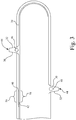
- Fig. 2 there is shown the draper belt 33 which is used to carry crop material towards the feederhouse 20 and which is positioned over guides and rollers (not shown) to simplify the understanding of the present invention.
- the draper belt 33 comprises an elongated base structure 34 having side edges 36, 38 and ends 40, 42.
- the base structure 34 is formed from fabric calendared with rubber and cured or vulcanized in a standard curing process in the industry.
- the base structure 34 has a plurality of cleats 44 extending laterally from adjacent one edge 36 to adjacent the other edge 38. As shown particularly in Fig. 3 , the cleats 44 have an elongated structural core 46 or 48 to provide sufficient rigidity to the cleat 44.
- the structural core 46 is diamond shape in cross-section and the core 48 has alternatively a tear drop cross-section shape with the widest section adjacent the base 34. It should be apparent to those skilled in the art that other cross-section shapes may also be employed.
- the cores 46, 48 are embedded in rubber having tapered working surfaces 30 and 32 with the widest portion of the cleat being adjacent the base material 12.
- the draper belt 33 additionally has a guide 50 opposite the face of base 34 containing the cleats 44.
- the guide 50 is shown in detail in Fig. 4 .
- Guide 50 is elongated extending in a direction substantially parallel to the longitudinal axis of the base structure 34 and having tapered faces 52 and 54.
- the guide 50 is tended to align the draper belt 33 so that it remains in a predetermined forward and aft position.
- the guide 50 is formed from the same rubber material in base 34 so that during curing or vulcanization it forms an integral flexible structural element.
- the belt 33 is manufactured by first providing the elongated base 34 having the first end 40 and the second end 42 with the rubber in an uncured state.
- the cleats 44 are formed from extrusions or molds of uncured rubber to the resultant tapered shape around the structural core 46 or 48. These elements are placed in a mold along the top surface along one face of the structure 34 and are uniformly spaced from and parallel to each other. At the same time the uncured rubber is applied to form the guide 50.
- the belt 33 is formed in sequenced sections from adjacent the first end 40 to the second end 42 of the base structure 34. The elements of the combination are cured except for a portion 56 and 58 adjacent ends 40 and 42, respectively of the base structure 34.
- the guide 50 is also interrupted over section 56 and 58.
- the side edges 36 and 38 can be folded over on themselves at 60 and 62 before curing to reinforce the side edges.
- the sections 56 and 58 containing the folded over edges are not yet cured.
- separate uncured rubber strips may be placed along the side edges 36 and 38 to form a re-enforcing hem,
- the end sections 56 and 58 are overlapped as shown particularly in Fig. 3 and that section cured to perform a seamless integral structure forming an endless draper belt. While a range of overlapping dimensions may be employed, an overlap of approximately 15.24 cm (6 inches) may be used.
Description
- The invention relates to agricultural harvesting machines, and more particularly to draper belts incorporated in such machines.
- An agricultural combine is a large machine used to harvest a variety of crops from a field. During a harvesting operation, a header at the front of the combine cuts ripened crop from the field. A feederhouse supporting the header transfers the crop material into the combine. Threshing and separating assemblies within the combine remove grain from the crop material and transfer the clean grain to a grain tank for temporary holding. Crop material other than grain exits from the rear of the combine. An unloading auger transfers the clean grain from the grain tank to a truck or grain cart for transport, or to another receiving bin for holding.
- Draper headers are header types commonly used when harvesting crops such as small grains, peas, lentils, and rice. Such draper headers comprise a cutter bar and two or more conveying transversely moving draper belts arranged in a forward direction behind the cutter bar that convey the cut crop towards the center of the header, where it is fed towards the rear by another conveyor belt assembly that feeds the crop towards a rear outlet of the header and to a feederhouse of the combine. During a harvesting operation with this header type, it is desirable to maintain a cutting height as low as possible to the ground in order to collect substantially the entire ripe crop from the field. To accomplish this, combines typically employ a header float system or a terrain following system to enable the header to follow the ground over changing terrain without gouging or digging into the soil.
- One of the key elements in the transverse movement of cut crop material is the draper belt. A pair of draper belts are usually provided and are mounted on rollers and actuated to cause the movement of crop material towards the center section. Draper belts are subjected to tension fluctuations and reversals in bending causing localized stress which leads to a life that is limited by the joint between the ends of the belt.
- It is standard practice to have a draper belt manufactured so that the ends are secured in situ on the draper header. The method of securing usually is with fasteners through a transverse end piece that meets to the adjacent end. However, there are sections of the belt that require a minimum clearance so as to require low profile fasteners in those sections. While current draper belts have significant reliability, their end sections usually are the limiting point of service life.
-
US 4 226 417 A , considered as generic, shows a seamless carpet belt for a pinspotter machine, comprising an elongated, flat base structure comprised of fabric and rubber. - Accordingly, what is needed in the art is a draper belt having increased flexibility and durability, primarily in the area of the joint.
- This object is achieved with the subject matter of claims 1 and 11. The dependent claims recite advantageous features of embodiments of the invention.
- A seamless draper belt is formed from an elongated flat base structure of fabric and rubber. A plurality of transverse cleats having a structural core embedded in rubber are connected to the base. The elongated base structure and cleats are cured and adhere to one another except for end sections to form a flexible elongated structure, the ends of the base structure being overlapped and cured to form a seamless belt.
- A method of making a seamless draper belt includes the steps of forming an elongated flat base structure of fabric and uncured rubber and having a first and second end. Cleats formed from a structural core embedded in uncured rubber are positioned on one face of the base structure. The molding and curing of the rubber over the cleat cores and adjacent base structure is done leaving a portion of the base structure adjacent the first and second ends being uncured. The uncured ends are then overlapped and cured to form an endless seamless draper belt.
- An embodiment of the invention is shown in the drawings, in which:
- Fig. 1
- is a side-view of a combine, showing a draper platform header.
- Fig. 2
- is a perspective view of a belt embodying the present invention;
- Fig. 3
- is a side view of the belt shown in
Fig. 2 , and - Fig. 4
- is an enlarged portion of the perspective view of
Fig 3 . -
Figure 1 illustrates a self-propelled combine 10 commonly used in a grain farming operation to harvest a variety of crops from a field. An onboard engine (not shown) powers the combine 10, while groundengaging wheels 14 support and propel the machine. An operator controls the combine 10 from an operator's station located in acab 16 at the front of the machine. - A
feederhouse 20 pivotally attaches at the front of the combine 10, supporting aheader 22 removably attached to the front of thefeederhouse 20. A pair oflift cylinders 24 support and articulate thefeederhouse 20 from the combine 10, enabling the raising and lowering of theheader 22 relative to the ground. - During a harvesting operation, the combine 10 moves forward through the field with the
header 22 lowered to a working height. Theheader 22 cuts and transfers crop material to thefeederhouse 20, which in turn transfers the crop material into the combine 10. Once inside the combine, threshing and separatingassemblies 26 remove grain from the non-grain crop material and transfer it to agrain tank 28 for temporary holding. Crop material other than grain exits from the rear of the combine 10. Anunloading auger 31 transfers the grain from thegrain tank 28 to a truck or grain cart for transport, or to another receiving bin for holding. In the following, all references to directions are quoted with respect to the forward direction of combine 10 which extends inFigure 1 to the left side. - An essential element of the header is a
draper belt 33 that transfers cut crop material laterally inward to thefeederhouse 20. Typically, a pair ofdraper belts 33 is provided to transfer cut crop material laterally to the central location of thefeederhouse 20. Referring now toFig. 2 , there is shown thedraper belt 33 which is used to carry crop material towards thefeederhouse 20 and which is positioned over guides and rollers (not shown) to simplify the understanding of the present invention. Thedraper belt 33 comprises anelongated base structure 34 havingside edges ends base structure 34 is formed from fabric calendared with rubber and cured or vulcanized in a standard curing process in the industry. Thebase structure 34 has a plurality ofcleats 44 extending laterally from adjacent oneedge 36 to adjacent theother edge 38. As shown particularly inFig. 3 , thecleats 44 have an elongatedstructural core cleat 44. Thestructural core 46 is diamond shape in cross-section and thecore 48 has alternatively a tear drop cross-section shape with the widest section adjacent thebase 34. It should be apparent to those skilled in the art that other cross-section shapes may also be employed. Thecores surfaces - The
draper belt 33 additionally has aguide 50 opposite the face ofbase 34 containing thecleats 44. Theguide 50 is shown in detail inFig. 4 .Guide 50 is elongated extending in a direction substantially parallel to the longitudinal axis of thebase structure 34 and havingtapered faces guide 50 is tended to align thedraper belt 33 so that it remains in a predetermined forward and aft position. Theguide 50 is formed from the same rubber material inbase 34 so that during curing or vulcanization it forms an integral flexible structural element. - The
belt 33 is manufactured by first providing theelongated base 34 having thefirst end 40 and thesecond end 42 with the rubber in an uncured state. - The
cleats 44 are formed from extrusions or molds of uncured rubber to the resultant tapered shape around thestructural core structure 34 and are uniformly spaced from and parallel to each other. At the same time the uncured rubber is applied to form theguide 50. In typical fashion thebelt 33 is formed in sequenced sections from adjacent thefirst end 40 to thesecond end 42 of thebase structure 34. The elements of the combination are cured except for aportion base structure 34. Theguide 50 is also interrupted oversection sections - Once the composite structure has been cured, the
end sections Fig. 3 and that section cured to perform a seamless integral structure forming an endless draper belt. While a range of overlapping dimensions may be employed, an overlap of approximately 15.24 cm (6 inches) may be used. - By eliminating mechanical joints in the
belt 33, extended durability is enhanced. It should be noted that the securing of the end sections in the fashion shown presents an extremely low profile without the height limitations of prior art draper belts that are assembled in the field.
Claims (15)
- A seamless draper belt (33) comprising an elongated, flat base structure (34) comprised of fabric and rubber; characterized by comprising a plurality of transverse cleats (44) having a structural core (46, 48) embedded in rubber connected to said base structure (34); said elongated base structure (34) and cleats (44) being cured and adhered to one another except for end sections (40, 42) to form a flexible elongated structure; the ends (40, 42) of said base structure (34) being overlapped and cured to form a seamless belt (33).
- The seamless draper belt (33) as claimed in claim 1, wherein said cleats (44) are uniformly spaced from one another on said flat base structure (34).
- The seamless draper belt (33) as claimed in claim 1, wherein said structural core (46) is elongate and has a diamond cross-sectional shape.
- The seamless draper belt (33) as claimed in claim 1, wherein said structural core (48) is elongate and has a tear drop shape with the widest portion of the tear drop shape adjacent the elongated flat base structure (34).
- The seamless draper belt (33) as claimed in claim 1, wherein said cleats (44) are tapered from their base adjacent the elongated base structure (34).
- The seamless draper belt (33) as claimed in claim 1, further comprising an elongated guide (50) on the face of the flat base structure (34) opposite to that of the cleats (44), said elongated guide (50) being formed of rubber and cured to make an uniform structure with said elongated flat base structure (34).
- The seamless draper belt (33) as claimed in claim 6, wherein said elongated guide (50) has a tapered cross-section from adjacent the elongated flat base structure (34).
- The seamless draper belt (33) as claimed in claim 6, wherein said elongated guide (50) is interrupted at the ends (40, 42) of said base structure (34) where they are overlapped.
- The seamless draper belt (33) as claimed in claim 1, wherein said base structure (34) has at least one of its side edges (36, 38) overlapped on itself and cured to form a uniform belt (33).
- A header (22) for a combine (10) removably attachable to the front of a feederhouse (20), the header (22) comprising a draper belt (33) according to one of claims 1 to 9 adapted to transfer cut crop material laterally inward to the feederhouse (20).
- A method of making a seamless draper belt (33) comprising the step of forming an elongated flat base structure (34) of fabric and uncured rubber, having a first and second end (40, 42); characterized by comprising the following steps: positioning to said base structure (34) on one face thereof a plurality of transverse cleats (44) formed from a structural core (46, 48) embedded in uncured rubber; molding and curing rubber over said structural cores (46, 48) and adjacent base structure (34), a portion of the base structure (34) adjacent the first and second ends (40, 42) being uncured; and overlapping and curing said first and second ends (40, 42) to form an endless seamless draper belt (33).
- The method of claim 11, wherein the cleats (44) are positioned on the base structure (34) at a uniformly spaced location.
- The method as claimed in claim 11, wherein the structural core (46) is diamond shaped in cross-section.
- The method as claimed in claim 11, wherein the structural core (48) has a tear drop cross section shape with the widest portion adjacent the elongated flat base structure (34).
- The method as claimed in claim 11, wherein the cleats (44) are formed into a tapered cross-section with the widest portion of the cleat (44) adjacent the elongated flat base structure (34).
Applications Claiming Priority (1)
| Application Number | Priority Date | Filing Date | Title |
|---|---|---|---|
| US12/164,667 US7543428B1 (en) | 2008-06-30 | 2008-06-30 | Seamless draper belt |
Publications (3)
| Publication Number | Publication Date |
|---|---|
| EP2140752A2 EP2140752A2 (en) | 2010-01-06 |
| EP2140752A3 EP2140752A3 (en) | 2017-07-19 |
| EP2140752B1 true EP2140752B1 (en) | 2018-08-22 |
Family
ID=40688587
Family Applications (1)
| Application Number | Title | Priority Date | Filing Date |
|---|---|---|---|
| EP09162657.2A Active EP2140752B1 (en) | 2008-06-30 | 2009-06-15 | Seamless draper belt |
Country Status (6)
| Country | Link |
|---|---|
| US (1) | US7543428B1 (en) |
| EP (1) | EP2140752B1 (en) |
| AU (1) | AU2009202391A1 (en) |
| BR (1) | BRPI0901938A2 (en) |
| CA (1) | CA2668979A1 (en) |
| RU (1) | RU2493690C2 (en) |
Families Citing this family (34)
| Publication number | Priority date | Publication date | Assignee | Title |
|---|---|---|---|---|
| US20080276590A1 (en) | 2006-02-10 | 2008-11-13 | Agco Corporation | Flexible draper and cutter bar with tilt arm for cutterbar drive |
| US20080271426A1 (en) | 2006-02-10 | 2008-11-06 | Agco Corporation | Draper belt with crop-retaining rib |
| US20070193243A1 (en) | 2006-02-10 | 2007-08-23 | Schmidt James R | Combine Harvester Draper Header Having Flexible Cutterbar |
| US20090266044A1 (en) | 2008-04-25 | 2009-10-29 | Coers Bruce A | Integrated draper belt support and skid shoe in an agricultural harvesting machine |
| US20090277148A1 (en) | 2008-05-09 | 2009-11-12 | Agco Corporation | Flexible draper and cutter bar having shiftable crop divider with deflector |
| US7921627B2 (en) | 2008-05-09 | 2011-04-12 | Agco Corporation | Interlocking belt guards for a draper header |
| WO2009136267A1 (en) | 2008-05-09 | 2009-11-12 | Agco Corporation | Center crop deflector for draper header |
| US20090277145A1 (en) | 2008-05-09 | 2009-11-12 | Agco Corporation | Header height control system with multiple potentiometer input |
| US20090277144A1 (en) | 2008-05-09 | 2009-11-12 | Agco Corporation | Spring flotation for center deck of draper header |
| US7886511B2 (en) | 2008-05-09 | 2011-02-15 | Agco Corporation | Draper head with flexible cutterbar having rigid center section |
| CA2722837C (en) | 2008-05-09 | 2017-10-03 | Agco Corporation | Adjustable cutterbar travel range for a flexible cutterbar header |
| US7661256B2 (en) * | 2008-07-10 | 2010-02-16 | Deere & Company | Hybrid seam for a draper belt in an agricultural harvester |
| DE102010004799A1 (en) * | 2010-01-16 | 2011-07-21 | ARTEMIS Kautschuk- und Kunststoff-Technik GmbH, 30559 | Conveyor belt for agricultural machinery, in particular for rakes |
| US8205421B2 (en) | 2010-06-16 | 2012-06-26 | Agco Corporation | Belt guard crop dam for flexible draper header |
| US7958711B1 (en) | 2010-06-16 | 2011-06-14 | Agco Corporation | Crop deflector for ends of draper belt of flexible draper header |
| US8479483B1 (en) | 2011-12-27 | 2013-07-09 | Agco Corporation | Flexible draper head providing reduced crop residue accumulation |
| BE1020497A3 (en) * | 2012-02-22 | 2013-11-05 | Cnh Belgium Nv | RECTANGULAR BALER PRESS FOR USE IN AGRICULTURE. |
| US9622412B2 (en) * | 2014-01-15 | 2017-04-18 | Deere & Company | Draper header with belt cleaning arrangement |
| US9456548B2 (en) * | 2014-02-14 | 2016-10-04 | Deere & Company | Conveyer for a material processing machine |
| BR112018005809B1 (en) * | 2015-09-30 | 2022-11-08 | Contitech Transportbandsysteme Gmbh | TRACK BELT WITH A RUBBER INSERTION INSIDE THE SHIMS TO INCREASE BELT DURABILITY AND REDUCE FIBERGLASS SHAFT |
| EP3356262B1 (en) * | 2015-09-30 | 2022-12-07 | ContiTech Transportbandsysteme GmbH | Draper belt having improved cleat design |
| US10676281B2 (en) * | 2015-09-30 | 2020-06-09 | Contitech Transportbandsysteme Gmbh | Draper belt having improved edge durability |
| WO2017190961A1 (en) * | 2016-05-03 | 2017-11-09 | Contitech Transportbandsysteme Gmbh | Smart draper belt |
| US10660266B2 (en) * | 2016-05-03 | 2020-05-26 | Contitech Transportbandsysteme Gmbh | System and method for monitoring an agricultural belt |
| WO2018172963A1 (en) * | 2017-03-21 | 2018-09-27 | Soucy International Inc. | Draper belt |
| US10314234B2 (en) | 2017-07-14 | 2019-06-11 | Cnh Industrial America Llc | Guide assembly for a lateral draper of a header for an agricultural harvester |
| CN107864740B (en) * | 2017-11-21 | 2021-03-12 | 柳州长保地农机制造有限公司 | Sugarcane cutting and conveying device |
| CN107864748B (en) * | 2017-11-21 | 2021-03-12 | 柳州长保地农机制造有限公司 | Conveying device of sugarcane harvester |
| AU2018271412A1 (en) * | 2017-11-30 | 2019-06-13 | Primary Sales Australia Pty Ltd | Conveyor Assembly For A Harvester |
| CN109239796B (en) * | 2018-09-05 | 2020-12-22 | 深圳市宏途创嘉科技有限公司 | Security check machine |
| US11297770B2 (en) * | 2019-11-13 | 2022-04-12 | Cnh Industrial America Llc | Draper belt assembly for an agricultural harvester |
| BR102021017401A2 (en) * | 2021-09-01 | 2023-03-14 | Gts Do Brasil Ltda. | CONVEYOR BELT FLIP |
| WO2023114796A1 (en) * | 2021-12-14 | 2023-06-22 | Legg Company, Inc. | Draper belt overlapped splicing |
| US20240008409A1 (en) * | 2022-07-05 | 2024-01-11 | Cnh Industrial America Llc | Belt support for draper header of agricultural vehicle |
Family Cites Families (12)
| Publication number | Priority date | Publication date | Assignee | Title |
|---|---|---|---|---|
| SU923427A1 (en) * | 1977-12-30 | 1982-04-30 | за витель ..х, -vncwj А.А. Лавров | Reaper conveyer |
| US4226417A (en) * | 1978-06-05 | 1980-10-07 | Camilleri Thomas M | Carpet belt |
| RU2004467C1 (en) * | 1991-07-05 | 1993-12-15 | Исаак Зиновьевич Вортман | Steeply inclined conveyer |
| US6406577B1 (en) * | 1991-12-20 | 2002-06-18 | 3M Innovative Properties Company | Method of making abrasive belt with an endless, seamless backing |
| US5698358A (en) * | 1992-11-27 | 1997-12-16 | Xerox Corporation | Process for fabricating a belt with a seam having a curvilinear S shaped profile |
| US5714290A (en) * | 1994-12-01 | 1998-02-03 | Xerox Corporation | Flexible belts having a bent seam |
| JPH08258934A (en) * | 1995-03-16 | 1996-10-08 | Atsusato Kitamura | Manufacture of loop-shaped belt |
| US6321903B1 (en) * | 1998-05-08 | 2001-11-27 | Curt Shaffer | Splice joint for plastic coated fabric conveyor belt and method of making the same |
| US6238131B1 (en) * | 1999-05-27 | 2001-05-29 | Deere & Company | Draper belt connector assembly for a harvesting machine |
| RU2262829C1 (en) * | 2004-04-12 | 2005-10-27 | Челябинский государственный агроинженерный университет (ЧГАУ) | Method for laying of grain heap windrow onto stubble and apparatus for performing the same |
| US20070238565A1 (en) * | 2006-03-27 | 2007-10-11 | Ron Marler | Draper belt having improved durability |
| US7344020B2 (en) * | 2005-06-10 | 2008-03-18 | Deere & Company | Belt connection for agriculture conveyor |
-
2008
- 2008-06-30 US US12/164,667 patent/US7543428B1/en active Active
-
2009
- 2009-06-15 CA CA002668979A patent/CA2668979A1/en not_active Abandoned
- 2009-06-15 EP EP09162657.2A patent/EP2140752B1/en active Active
- 2009-06-15 AU AU2009202391A patent/AU2009202391A1/en not_active Abandoned
- 2009-06-16 RU RU2009122946/13A patent/RU2493690C2/en not_active IP Right Cessation
- 2009-06-26 BR BRPI0901938-3A patent/BRPI0901938A2/en not_active Application Discontinuation
Non-Patent Citations (1)
| Title |
|---|
| None * |
Also Published As
| Publication number | Publication date |
|---|---|
| US7543428B1 (en) | 2009-06-09 |
| RU2493690C2 (en) | 2013-09-27 |
| BRPI0901938A2 (en) | 2010-04-13 |
| EP2140752A2 (en) | 2010-01-06 |
| CA2668979A1 (en) | 2009-12-30 |
| RU2009122946A (en) | 2010-12-27 |
| EP2140752A3 (en) | 2017-07-19 |
| AU2009202391A1 (en) | 2010-01-14 |
Similar Documents
| Publication | Publication Date | Title |
|---|---|---|
| EP2140752B1 (en) | Seamless draper belt | |
| US7650737B1 (en) | Reel finger for use on a harvesting header for an agricultural machine | |
| US7640720B1 (en) | Draper belt construction to control translation | |
| EP1993344B1 (en) | Flexible cutting platform to follow ground contour in an agricultural harvesting machine | |
| US7540130B2 (en) | Height control for a multi-section cutting platform in an agricultural harvesting machine | |
| US8281561B2 (en) | Flexible draper belt drive for an agricultural harvesting machine | |
| US20070204589A1 (en) | Sectionalized belt guide for draper belt in an agricultural harvesting machine | |
| US20070204585A1 (en) | Lockout for float arms in a cutting platform of an agricultural harvesting machine | |
| US7661256B2 (en) | Hybrid seam for a draper belt in an agricultural harvester | |
| US20130160417A1 (en) | Flexible draper head providing reduced crop residue accumulation | |
| EP3356262B1 (en) | Draper belt having improved cleat design | |
| JP5194511B2 (en) | Root crop harvesting machine | |
| EP3355681B1 (en) | Draper belt with a rubber insert inside the cleats | |
| JP5204818B2 (en) | Combine | |
| JP6537447B2 (en) | Work machine |
Legal Events
| Date | Code | Title | Description |
|---|---|---|---|
| PUAI | Public reference made under article 153(3) epc to a published international application that has entered the european phase |
Free format text: ORIGINAL CODE: 0009012 |
|
| AK | Designated contracting states |
Kind code of ref document: A2 Designated state(s): AT BE BG CH CY CZ DE DK EE ES FI FR GB GR HR HU IE IS IT LI LT LU LV MC MK MT NL NO PL PT RO SE SI SK TR |
|
| PUAL | Search report despatched |
Free format text: ORIGINAL CODE: 0009013 |
|
| AK | Designated contracting states |
Kind code of ref document: A3 Designated state(s): AT BE BG CH CY CZ DE DK EE ES FI FR GB GR HR HU IE IS IT LI LT LU LV MC MK MT NL NO PL PT RO SE SI SK TR |
|
| RIC1 | Information provided on ipc code assigned before grant |
Ipc: A01D 61/02 20060101ALI20170615BHEP Ipc: B65G 15/42 20060101ALI20170615BHEP Ipc: B65G 17/02 20060101ALI20170615BHEP Ipc: B65G 15/44 20060101ALI20170615BHEP Ipc: A01D 57/20 20060101AFI20170615BHEP Ipc: B65G 15/52 20060101ALI20170615BHEP |
|
| STAA | Information on the status of an ep patent application or granted ep patent |
Free format text: STATUS: REQUEST FOR EXAMINATION WAS MADE |
|
| 17P | Request for examination filed |
Effective date: 20180119 |
|
| RBV | Designated contracting states (corrected) |
Designated state(s): AT BE BG CH CY CZ DE DK EE ES FI FR GB GR HR HU IE IS IT LI LT LU LV MC MK MT NL NO PL PT RO SE SI SK TR |
|
| GRAP | Despatch of communication of intention to grant a patent |
Free format text: ORIGINAL CODE: EPIDOSNIGR1 |
|
| STAA | Information on the status of an ep patent application or granted ep patent |
Free format text: STATUS: GRANT OF PATENT IS INTENDED |
|
| RIC1 | Information provided on ipc code assigned before grant |
Ipc: B65G 15/42 20060101ALI20180216BHEP Ipc: B65G 15/44 20060101ALI20180216BHEP Ipc: B65G 17/02 20060101ALI20180216BHEP Ipc: B65G 15/52 20060101ALI20180216BHEP Ipc: A01D 61/02 20060101ALI20180216BHEP Ipc: A01D 57/20 20060101AFI20180216BHEP |
|
| INTG | Intention to grant announced |
Effective date: 20180319 |
|
| GRAS | Grant fee paid |
Free format text: ORIGINAL CODE: EPIDOSNIGR3 |
|
| GRAA | (expected) grant |
Free format text: ORIGINAL CODE: 0009210 |
|
| STAA | Information on the status of an ep patent application or granted ep patent |
Free format text: STATUS: THE PATENT HAS BEEN GRANTED |
|
| AK | Designated contracting states |
Kind code of ref document: B1 Designated state(s): AT BE BG CH CY CZ DE DK EE ES FI FR GB GR HR HU IE IS IT LI LT LU LV MC MK MT NL NO PL PT RO SE SI SK TR |
|
| REG | Reference to a national code |
Ref country code: GB Ref legal event code: FG4D |
|
| REG | Reference to a national code |
Ref country code: CH Ref legal event code: EP |
|
| REG | Reference to a national code |
Ref country code: DE Ref legal event code: R096 Ref document number: 602009053973 Country of ref document: DE |
|
| REG | Reference to a national code |
Ref country code: AT Ref legal event code: REF Ref document number: 1031348 Country of ref document: AT Kind code of ref document: T Effective date: 20180915 |
|
| REG | Reference to a national code |
Ref country code: IE Ref legal event code: FG4D |
|
| REG | Reference to a national code |
Ref country code: NL Ref legal event code: MP Effective date: 20180822 |
|
| REG | Reference to a national code |
Ref country code: LT Ref legal event code: MG4D |
|
| PG25 | Lapsed in a contracting state [announced via postgrant information from national office to epo] |
Ref country code: IS Free format text: LAPSE BECAUSE OF FAILURE TO SUBMIT A TRANSLATION OF THE DESCRIPTION OR TO PAY THE FEE WITHIN THE PRESCRIBED TIME-LIMIT Effective date: 20181222 Ref country code: NL Free format text: LAPSE BECAUSE OF FAILURE TO SUBMIT A TRANSLATION OF THE DESCRIPTION OR TO PAY THE FEE WITHIN THE PRESCRIBED TIME-LIMIT Effective date: 20180822 Ref country code: FI Free format text: LAPSE BECAUSE OF FAILURE TO SUBMIT A TRANSLATION OF THE DESCRIPTION OR TO PAY THE FEE WITHIN THE PRESCRIBED TIME-LIMIT Effective date: 20180822 Ref country code: LT Free format text: LAPSE BECAUSE OF FAILURE TO SUBMIT A TRANSLATION OF THE DESCRIPTION OR TO PAY THE FEE WITHIN THE PRESCRIBED TIME-LIMIT Effective date: 20180822 Ref country code: GR Free format text: LAPSE BECAUSE OF FAILURE TO SUBMIT A TRANSLATION OF THE DESCRIPTION OR TO PAY THE FEE WITHIN THE PRESCRIBED TIME-LIMIT Effective date: 20181123 Ref country code: BG Free format text: LAPSE BECAUSE OF FAILURE TO SUBMIT A TRANSLATION OF THE DESCRIPTION OR TO PAY THE FEE WITHIN THE PRESCRIBED TIME-LIMIT Effective date: 20181122 Ref country code: NO Free format text: LAPSE BECAUSE OF FAILURE TO SUBMIT A TRANSLATION OF THE DESCRIPTION OR TO PAY THE FEE WITHIN THE PRESCRIBED TIME-LIMIT Effective date: 20181122 Ref country code: SE Free format text: LAPSE BECAUSE OF FAILURE TO SUBMIT A TRANSLATION OF THE DESCRIPTION OR TO PAY THE FEE WITHIN THE PRESCRIBED TIME-LIMIT Effective date: 20180822 |
|
| REG | Reference to a national code |
Ref country code: AT Ref legal event code: MK05 Ref document number: 1031348 Country of ref document: AT Kind code of ref document: T Effective date: 20180822 |
|
| PG25 | Lapsed in a contracting state [announced via postgrant information from national office to epo] |
Ref country code: HR Free format text: LAPSE BECAUSE OF FAILURE TO SUBMIT A TRANSLATION OF THE DESCRIPTION OR TO PAY THE FEE WITHIN THE PRESCRIBED TIME-LIMIT Effective date: 20180822 Ref country code: LV Free format text: LAPSE BECAUSE OF FAILURE TO SUBMIT A TRANSLATION OF THE DESCRIPTION OR TO PAY THE FEE WITHIN THE PRESCRIBED TIME-LIMIT Effective date: 20180822 Ref country code: ES Free format text: LAPSE BECAUSE OF FAILURE TO SUBMIT A TRANSLATION OF THE DESCRIPTION OR TO PAY THE FEE WITHIN THE PRESCRIBED TIME-LIMIT Effective date: 20180822 |
|
| PG25 | Lapsed in a contracting state [announced via postgrant information from national office to epo] |
Ref country code: RO Free format text: LAPSE BECAUSE OF FAILURE TO SUBMIT A TRANSLATION OF THE DESCRIPTION OR TO PAY THE FEE WITHIN THE PRESCRIBED TIME-LIMIT Effective date: 20180822 Ref country code: CZ Free format text: LAPSE BECAUSE OF FAILURE TO SUBMIT A TRANSLATION OF THE DESCRIPTION OR TO PAY THE FEE WITHIN THE PRESCRIBED TIME-LIMIT Effective date: 20180822 Ref country code: AT Free format text: LAPSE BECAUSE OF FAILURE TO SUBMIT A TRANSLATION OF THE DESCRIPTION OR TO PAY THE FEE WITHIN THE PRESCRIBED TIME-LIMIT Effective date: 20180822 Ref country code: PL Free format text: LAPSE BECAUSE OF FAILURE TO SUBMIT A TRANSLATION OF THE DESCRIPTION OR TO PAY THE FEE WITHIN THE PRESCRIBED TIME-LIMIT Effective date: 20180822 Ref country code: EE Free format text: LAPSE BECAUSE OF FAILURE TO SUBMIT A TRANSLATION OF THE DESCRIPTION OR TO PAY THE FEE WITHIN THE PRESCRIBED TIME-LIMIT Effective date: 20180822 |
|
| REG | Reference to a national code |
Ref country code: DE Ref legal event code: R097 Ref document number: 602009053973 Country of ref document: DE |
|
| PG25 | Lapsed in a contracting state [announced via postgrant information from national office to epo] |
Ref country code: DK Free format text: LAPSE BECAUSE OF FAILURE TO SUBMIT A TRANSLATION OF THE DESCRIPTION OR TO PAY THE FEE WITHIN THE PRESCRIBED TIME-LIMIT Effective date: 20180822 Ref country code: SK Free format text: LAPSE BECAUSE OF FAILURE TO SUBMIT A TRANSLATION OF THE DESCRIPTION OR TO PAY THE FEE WITHIN THE PRESCRIBED TIME-LIMIT Effective date: 20180822 |
|
| PLBE | No opposition filed within time limit |
Free format text: ORIGINAL CODE: 0009261 |
|
| STAA | Information on the status of an ep patent application or granted ep patent |
Free format text: STATUS: NO OPPOSITION FILED WITHIN TIME LIMIT |
|
| 26N | No opposition filed |
Effective date: 20190523 |
|
| PG25 | Lapsed in a contracting state [announced via postgrant information from national office to epo] |
Ref country code: SI Free format text: LAPSE BECAUSE OF FAILURE TO SUBMIT A TRANSLATION OF THE DESCRIPTION OR TO PAY THE FEE WITHIN THE PRESCRIBED TIME-LIMIT Effective date: 20180822 |
|
| PG25 | Lapsed in a contracting state [announced via postgrant information from national office to epo] |
Ref country code: MC Free format text: LAPSE BECAUSE OF FAILURE TO SUBMIT A TRANSLATION OF THE DESCRIPTION OR TO PAY THE FEE WITHIN THE PRESCRIBED TIME-LIMIT Effective date: 20180822 |
|
| REG | Reference to a national code |
Ref country code: CH Ref legal event code: PL |
|
| GBPC | Gb: european patent ceased through non-payment of renewal fee |
Effective date: 20190615 |
|
| PG25 | Lapsed in a contracting state [announced via postgrant information from national office to epo] |
Ref country code: TR Free format text: LAPSE BECAUSE OF FAILURE TO SUBMIT A TRANSLATION OF THE DESCRIPTION OR TO PAY THE FEE WITHIN THE PRESCRIBED TIME-LIMIT Effective date: 20180822 |
|
| PG25 | Lapsed in a contracting state [announced via postgrant information from national office to epo] |
Ref country code: IE Free format text: LAPSE BECAUSE OF NON-PAYMENT OF DUE FEES Effective date: 20190615 Ref country code: GB Free format text: LAPSE BECAUSE OF NON-PAYMENT OF DUE FEES Effective date: 20190615 |
|
| PG25 | Lapsed in a contracting state [announced via postgrant information from national office to epo] |
Ref country code: LU Free format text: LAPSE BECAUSE OF NON-PAYMENT OF DUE FEES Effective date: 20190615 Ref country code: LI Free format text: LAPSE BECAUSE OF NON-PAYMENT OF DUE FEES Effective date: 20190630 Ref country code: CH Free format text: LAPSE BECAUSE OF NON-PAYMENT OF DUE FEES Effective date: 20190630 |
|
| PG25 | Lapsed in a contracting state [announced via postgrant information from national office to epo] |
Ref country code: PT Free format text: LAPSE BECAUSE OF FAILURE TO SUBMIT A TRANSLATION OF THE DESCRIPTION OR TO PAY THE FEE WITHIN THE PRESCRIBED TIME-LIMIT Effective date: 20181222 Ref country code: FR Free format text: LAPSE BECAUSE OF NON-PAYMENT OF DUE FEES Effective date: 20190630 |
|
| PG25 | Lapsed in a contracting state [announced via postgrant information from national office to epo] |
Ref country code: CY Free format text: LAPSE BECAUSE OF FAILURE TO SUBMIT A TRANSLATION OF THE DESCRIPTION OR TO PAY THE FEE WITHIN THE PRESCRIBED TIME-LIMIT Effective date: 20180822 |
|
| PG25 | Lapsed in a contracting state [announced via postgrant information from national office to epo] |
Ref country code: HU Free format text: LAPSE BECAUSE OF FAILURE TO SUBMIT A TRANSLATION OF THE DESCRIPTION OR TO PAY THE FEE WITHIN THE PRESCRIBED TIME-LIMIT; INVALID AB INITIO Effective date: 20090615 Ref country code: MT Free format text: LAPSE BECAUSE OF FAILURE TO SUBMIT A TRANSLATION OF THE DESCRIPTION OR TO PAY THE FEE WITHIN THE PRESCRIBED TIME-LIMIT Effective date: 20180822 |
|
| PG25 | Lapsed in a contracting state [announced via postgrant information from national office to epo] |
Ref country code: MK Free format text: LAPSE BECAUSE OF FAILURE TO SUBMIT A TRANSLATION OF THE DESCRIPTION OR TO PAY THE FEE WITHIN THE PRESCRIBED TIME-LIMIT Effective date: 20180822 |
|
| PGFP | Annual fee paid to national office [announced via postgrant information from national office to epo] |
Ref country code: IT Payment date: 20220621 Year of fee payment: 14 |
|
| PGFP | Annual fee paid to national office [announced via postgrant information from national office to epo] |
Ref country code: DE Payment date: 20230522 Year of fee payment: 15 |
|
| PGFP | Annual fee paid to national office [announced via postgrant information from national office to epo] |
Ref country code: BE Payment date: 20230627 Year of fee payment: 15 |