EP3356262B1 - Draper belt having improved cleat design - Google Patents
Draper belt having improved cleat design Download PDFInfo
- Publication number
- EP3356262B1 EP3356262B1 EP16852296.9A EP16852296A EP3356262B1 EP 3356262 B1 EP3356262 B1 EP 3356262B1 EP 16852296 A EP16852296 A EP 16852296A EP 3356262 B1 EP3356262 B1 EP 3356262B1
- Authority
- EP
- European Patent Office
- Prior art keywords
- cleats
- belt
- draper belt
- draper
- cord
- Prior art date
- Legal status (The legal status is an assumption and is not a legal conclusion. Google has not performed a legal analysis and makes no representation as to the accuracy of the status listed.)
- Active
Links
- 230000003014 reinforcing effect Effects 0.000 claims description 37
- 229920001971 elastomer Polymers 0.000 claims description 24
- 239000005060 rubber Substances 0.000 claims description 23
- 229910000831 Steel Inorganic materials 0.000 claims description 14
- 239000010959 steel Substances 0.000 claims description 14
- 150000001875 compounds Chemical class 0.000 claims description 8
- 239000000463 material Substances 0.000 claims description 5
- 229910001369 Brass Inorganic materials 0.000 claims description 3
- 239000010951 brass Substances 0.000 claims description 3
- 239000004753 textile Substances 0.000 claims description 3
- 239000004699 Ultra-high molecular weight polyethylene Substances 0.000 claims description 2
- 239000011248 coating agent Substances 0.000 claims description 2
- 238000000576 coating method Methods 0.000 claims description 2
- 238000003825 pressing Methods 0.000 claims description 2
- 229920000785 ultra high molecular weight polyethylene Polymers 0.000 claims description 2
- 239000002759 woven fabric Substances 0.000 claims description 2
- 235000013339 cereals Nutrition 0.000 description 18
- 239000004744 fabric Substances 0.000 description 11
- 238000003306 harvesting Methods 0.000 description 9
- 239000002184 metal Substances 0.000 description 9
- 229910003460 diamond Inorganic materials 0.000 description 5
- 239000010432 diamond Substances 0.000 description 5
- 239000011152 fibreglass Substances 0.000 description 5
- 239000000853 adhesive Substances 0.000 description 4
- 230000001070 adhesive effect Effects 0.000 description 4
- 239000002131 composite material Substances 0.000 description 4
- 230000002787 reinforcement Effects 0.000 description 4
- 241000196324 Embryophyta Species 0.000 description 3
- 241001124569 Lycaenidae Species 0.000 description 3
- 239000004677 Nylon Substances 0.000 description 3
- 229920001778 nylon Polymers 0.000 description 3
- 244000068988 Glycine max Species 0.000 description 2
- 235000010469 Glycine max Nutrition 0.000 description 2
- 230000006978 adaptation Effects 0.000 description 2
- 238000005516 engineering process Methods 0.000 description 2
- 238000000034 method Methods 0.000 description 2
- 239000004033 plastic Substances 0.000 description 2
- 229920003023 plastic Polymers 0.000 description 2
- 239000004575 stone Substances 0.000 description 2
- 235000007319 Avena orientalis Nutrition 0.000 description 1
- 244000075850 Avena orientalis Species 0.000 description 1
- 235000014698 Brassica juncea var multisecta Nutrition 0.000 description 1
- 235000006008 Brassica napus var napus Nutrition 0.000 description 1
- 240000000385 Brassica napus var. napus Species 0.000 description 1
- 235000006618 Brassica rapa subsp oleifera Nutrition 0.000 description 1
- 235000004977 Brassica sinapistrum Nutrition 0.000 description 1
- 229910000975 Carbon steel Inorganic materials 0.000 description 1
- 244000020551 Helianthus annuus Species 0.000 description 1
- 235000003222 Helianthus annuus Nutrition 0.000 description 1
- 240000005979 Hordeum vulgare Species 0.000 description 1
- 235000007340 Hordeum vulgare Nutrition 0.000 description 1
- 235000004431 Linum usitatissimum Nutrition 0.000 description 1
- 240000006240 Linum usitatissimum Species 0.000 description 1
- 241000209056 Secale Species 0.000 description 1
- 235000007238 Secale cereale Nutrition 0.000 description 1
- 235000021307 Triticum Nutrition 0.000 description 1
- 244000098338 Triticum aestivum Species 0.000 description 1
- 240000008042 Zea mays Species 0.000 description 1
- 235000005824 Zea mays ssp. parviglumis Nutrition 0.000 description 1
- 235000002017 Zea mays subsp mays Nutrition 0.000 description 1
- 239000010962 carbon steel Substances 0.000 description 1
- 239000000969 carrier Substances 0.000 description 1
- 230000015556 catabolic process Effects 0.000 description 1
- 235000005822 corn Nutrition 0.000 description 1
- 238000013036 cure process Methods 0.000 description 1
- 238000006731 degradation reaction Methods 0.000 description 1
- 238000000465 moulding Methods 0.000 description 1
- 229920003052 natural elastomer Polymers 0.000 description 1
- 229920001194 natural rubber Polymers 0.000 description 1
- 230000000704 physical effect Effects 0.000 description 1
- 239000010908 plant waste Substances 0.000 description 1
- 230000004051 prolonged sun exposure Effects 0.000 description 1
- 150000003839 salts Chemical class 0.000 description 1
- 239000007787 solid Substances 0.000 description 1
- 238000009987 spinning Methods 0.000 description 1
- 229920003048 styrene butadiene rubber Polymers 0.000 description 1
- 239000000126 substance Substances 0.000 description 1
- 229920003051 synthetic elastomer Polymers 0.000 description 1
- 239000005061 synthetic rubber Substances 0.000 description 1
- XLYOFNOQVPJJNP-UHFFFAOYSA-N water Substances O XLYOFNOQVPJJNP-UHFFFAOYSA-N 0.000 description 1
Images


Classifications
-
- B—PERFORMING OPERATIONS; TRANSPORTING
- B65—CONVEYING; PACKING; STORING; HANDLING THIN OR FILAMENTARY MATERIAL
- B65G—TRANSPORT OR STORAGE DEVICES, e.g. CONVEYORS FOR LOADING OR TIPPING, SHOP CONVEYOR SYSTEMS OR PNEUMATIC TUBE CONVEYORS
- B65G15/00—Conveyors having endless load-conveying surfaces, i.e. belts and like continuous members, to which tractive effort is transmitted by means other than endless driving elements of similar configuration
- B65G15/30—Belts or like endless load-carriers
- B65G15/32—Belts or like endless load-carriers made of rubber or plastics
- B65G15/42—Belts or like endless load-carriers made of rubber or plastics having ribs, ridges, or other surface projections
-
- A—HUMAN NECESSITIES
- A01—AGRICULTURE; FORESTRY; ANIMAL HUSBANDRY; HUNTING; TRAPPING; FISHING
- A01D—HARVESTING; MOWING
- A01D57/00—Delivering mechanisms for harvesters or mowers
- A01D57/20—Delivering mechanisms for harvesters or mowers with conveyor belts
-
- A—HUMAN NECESSITIES
- A01—AGRICULTURE; FORESTRY; ANIMAL HUSBANDRY; HUNTING; TRAPPING; FISHING
- A01D—HARVESTING; MOWING
- A01D61/00—Elevators or conveyors for binders or combines
- A01D61/02—Endless belts
-
- B—PERFORMING OPERATIONS; TRANSPORTING
- B65—CONVEYING; PACKING; STORING; HANDLING THIN OR FILAMENTARY MATERIAL
- B65G—TRANSPORT OR STORAGE DEVICES, e.g. CONVEYORS FOR LOADING OR TIPPING, SHOP CONVEYOR SYSTEMS OR PNEUMATIC TUBE CONVEYORS
- B65G15/00—Conveyors having endless load-conveying surfaces, i.e. belts and like continuous members, to which tractive effort is transmitted by means other than endless driving elements of similar configuration
- B65G15/30—Belts or like endless load-carriers
- B65G15/32—Belts or like endless load-carriers made of rubber or plastics
- B65G15/34—Belts or like endless load-carriers made of rubber or plastics with reinforcing layers, e.g. of fabric
Definitions
- the field to which the disclosure generally relates is harvesting machines, and more particularly to draper belts having significantly more durable cleats.
- Agricultural harvesting machines such as combine harvesters are used to reap, thresh, and winnow grain crops such as wheat, rye, barley, corn, soybeans, oats, flax, sunflower, and canola. More specifically, combine harvesters are used to cut grain crops at the base, separate the grains from the remainder of the plant (the chaff), and sort the grain from the chaff. These machines require special adaptations to accommodate specific crops, navigate through field landscapes, and resist damage from the crops, stone, and the elements; especially moisture and high temperature which can lead to the degradation of the machine's rubber components.
- Generally harvesting machines gather crops using a header having crop dividers which define crop gathering gaps as the machine moves through a field.
- the gathered crops are pushed by a reel into a cutter bar, which runs the length of the header and is equipped with teeth made of metal or plastic to cut crops at their base.
- Headers may have a rigid or flexible header platform depending upon the operator's needs.
- Flexible header platforms, or "flex headers” have a cutter bar which is capable of flexing over uneven terrain.
- Machines using flex headers are most often used to cut soybeans, whereas conventional header platforms have a rigid cutter bar and are most often used to cut cereal crops.
- Freshly cut crops fall behind the cutter bar and onto a plurality of side by side draper belts which are wrapped around parallel spaced rollers.
- Draper belts function primarily to consolidate crops and move the crops from the header towards the threshing drum. Crops are fed into the threshing drum by spinning augurs. Inside the threshing drum, the grains are shaken from the plant. Grains fall through sieves into a grain collecting tank, and the plant waste, or chaff, is moved to the back of the machine by conveyor belts for later disposal.
- Draper belts are an important component of agricultural harvesters. These belts are often subject to prolonged sun exposure, high temperatures, cold temperatures, rain and moisture, dirt and stone, as well as excessive friction from the moving machinery and crops. Furthermore water is known to migrate through the rubber belts carrying corrosive elements and salts which degrade the belt. Draper belts are typically called upon to operate for long periods of time. For these reasons, it is necessary that draper belts be specially adapted to maximize durability and service life, and it is desirable for such adaptations to be cost effective.
- United States Patent 8,544,250 discloses a draper platform having a center endless belt conveyor that is supported on and between first and second adjacent support arms.
- the endless conveyor belt has laterally extending cleats bonded thereto that engage the crop and assist in dragging the crop along the belt.
- United States Patent 7,543,428 shows a seamless draper belt formed from an elongated flat base structure of fabric and rubber, and transverse cleats having a structural core embedded in rubber are connected to the base. Cleats formed from a structural core embedded in uncured rubber are positioned on one face of the base structure. The molding and curing of the rubber over the cleat cores and adjacent base structure is done leaving a portion of the base structure adjacent the first and second ends being uncured. The uncured ends are then overlapped and cured to form an endless seamless draper belt.
- United States Patent 6,817,166 describes a feed draper carrying cleats which are angled to the rollers in two sections converging to a central leading apex to reduce forces on the cleat as they pass over the front guide roller which is of reduced diameter to fit within a small space adjacent the cutter bar.
- Such cleats are often reinforced by a rod inside the molded material of the cleat, which is generally a resilient natural or synthetic rubber material.
- the draper canvas having on its outer surface a plurality of generally transversely extending longitudinally spaced cleats attached to the outer surface and extending outwardly there from for engaging the cop and providing a longitudinal force on the crop.
- United States Patent 7,478,521 discloses a cutting platform for use with an agricultural harvesting machine which includes a plurality of platform sections positioned in end-to-end juxtaposed relation to each other. At least one platform section includes a frame, a plurality of float arms movably coupled with the frame, an endless belt carried by the plurality of float arms, and a cutter bar assembly carried by the plurality of float arms and movable in a localized manner in upwards and downwards directions.
- the endless belt has a plurality of spaced apart cleats which do not extend to the lateral side edges thereof, allowing the belt to travel between belt guides and upper run carriers without unnecessary clearance space there between.
- United States Patent Application 2007/0238565 A1 discloses a draper belt according to the preamble of claim 1.
- draper belts of the prior art It is common for draper belts of the prior art to fail for one or more reasons. Frequently draper belt cleats become worn and damaged from use, and this exposes fiberglass rods within the cleats which provide the cleats with lateral support. To reduce this problem, manufacturers of agricultural machinery have redesigned combine headers and the like; however, draper belt cleats remain unusually prone to damage and wear in all known machine and header designs. Accordingly there is a need for a specially adapted draper belt having significantly more durable cleats than the draper belt cleats of the prior art.
- the present invention is directed to specially adapted draper belts which offer improved durability and an extended service life.
- the draper belts of the present invention include cleats having enhanced resistant to damage. This improved resistance to damage is attained by virtue of the cleats in the draper belts of this disclosure being made with reinforcing rods which are comprised of a metal, such as carbon steel.
- the metal rods used in the cleats of the draper belts of the present invention are a significant improvement over the nylon and fiberglass rods of the prior art for at least four reasons. First, the metal rods provide excellent lateral support to the cleats at a minimal cost. Second, the draper belts of this disclosure have improved processing times. Third, the metal rods are more wear resistant than the nylon or fiberglass rods of the prior art. Fourth, the metal rods can be made to have better adhesion to the rubber cleats than nylon or fiberglass reinforcing rods.
- draper belts have a carry layer, a pulley cover layer, and a reinforcing layer which is situated between the carry layer and the pulley cover layer, wherein the draper belt has a first edge and a second edge, wherein the carry layer includes a plurality of cleats which run from the first edge to the second edge of the draper belt, and wherein the cleats are reinforced with reinforcing rods which are comprised of a metal.
- a method for adhering reinforcing rods to the cleats includes extruding wire strips with an adhesive compound, wherein the wire is comprised of the metal to be used in the reinforcing rods, cutting the extruded wire strips and strips of fabric to specified lengths, wherein the fabric is comprised of the fabric to be used in the cleats, laying the extruded wire strips onto the fabric strips, curing the fabric strips and the wire, and simultaneously adding steel and rubber composite into a cavity centrally located within the cleat.
- the reinforcing rods are adhered to the cleats by coating steel cord with brass and applying a rubber to the cords, and pressing the coated cord and rubber compound into a series of rollers until the cord is adhered to the rubber, wherein the reinforcing rods are comprised of the coated steel cord and the cleats are comprised of the rubber.
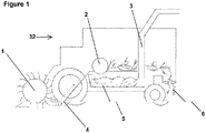
- Figure 1 depicts a conventional harvesting machine 32 having a reel 1, a cutter bar 4, a threshing drum 2, and a grain elevator 3.
- the reel 1 functions to move crops into the cutter bar 4 which cuts the crops at their base using metal or plastic teeth. Cut crops fall upon a plurality of side by side draper belts which consolidate the crops and move them towards the threshing drum 2.
- the threshing drum 2 beats and breaks the crops to shake the grains 5 from the remainder of the plant, also known as the chaff 6.
- the grains 5 are collected inside a grain collecting tank. When the grain collecting tank is full, operators dispose of the chaff 6 through the back of the machine 32, and grains 5 are moved from the grain tank by a grain elevator 3.
- FIG 2 shows a draper belt 8 as used in a conventional agricultural harvesting machine having a reel 9, a threshing drum 10, and a cutter bar 11.
- the draper belt 8 is typically an endless belt which forms a continuous loop, and the ends of this belt can be fused, bonded, riveted, or secured by a mechanical splice.
- the draper belt 8 has cleats 7 located on carry layer 14, and the cleats 7 run from a first edge 30 and a second edge 31 of the draper belt 8.
- the carry 14 layer can be chosen from a wide variety of rubbery polymers having a desired combination of physical properties and chemical resistance. Most often, draper belts 8 of this disclosure are made using styrene-butadiene rubber (SBR).
- SBR styrene-butadiene rubber
- Figures 3 through 6 show some embodiments of the draper belt 8.
- Figure 3 shows a draper belt 8 having a carry layer 14, a pulley cover layer 13, and a reinforcing layer 12 located between the carry layer 14 and the pulley cover layer 13.
- the carry layer 14 includes a plurality of cleats 13 reinforced with reinforcing rods 15.
- the draper belt 8 of Figure 3 shows that the reinforcing rods 15 can be designed to have a teardrop shape.
- the teardrop shaped rod 15 generally has a rounded end 23 pointing towards the reinforcing layer 12 of the belt 8, and a pointed or narrowed end 22 pointing upwards from the carry layer 14 of the belt 8.
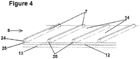
- Figure 4 shows that the reinforcing rods 20 can be designed to have an inverted "T" shape.
- the inverted "T" shaped rod 20 has a flattened elongated end 25 facing the reinforcing layer 12 of the belt 8, and a pointed or narrowed end 24 pointing upwards from the carry layer 14 of the belt.
- the draper belt 8 of Figure 5 shows that the reinforcing rods 18 of this disclosure can be designed to have a diamond or squared shape.
- the diamond shape of these reinforcing rods 18 may have rounded points or sharp points at each end 26, 27, and each end 26, 27 of the diamond shaped reinforcing rod 18 is substantially the same in size.
- the top end 26 of the diamond shaped rod 18 can be narrower than the lower end 27 of the diamond shaped rod 18.
- the draper belt 8 of Figure 6 shows that the reinforcing rods 19 of this disclosure can be designed to have an "L" shape.
- the "L” shaped rod 19 has a bottom end 29 facing towards the reinforcing layer 12 of the belt 8, and a pointed or narrowed top end 28 pointing upwardly from the carry layer 14 of the belt.
- the top and bottom ends 28, 29 are roughly perpendicular to one another, in a manner which allows them to meet at an angle of approximately 90o.
- the reinforcing rods can be of a "J" shape wherein the bottom end 29 of the reinforcing rod 19 curves away from the top end 28 of the reinforcing rod 19.
- the reinforcing rods 15, 18, 19, 20, can be of any desirable shape to reinforce the cleat.
- the rods 15, 18, 19, 20 are comprised of a twisted cable steel tire cord.
- the steel cord is comprised of single strand, multi-end strips of wire which are extruded with an adhesive compound in order to facilitate proper adhesion between the steel cord and the fabric of the cleats.
- Stranded wire is more flexible than solid wire of equal size, and for this reason it is ideal for use in reinforcing rods 15, 18, 19, 20.
- the steel cord can be adhered to the cleats 7 through the following steps.
- the rods 15, 18, 19, 20 are comprised of these wires.
- Second, the extruded strips of wire and strips of fabric are cut to the lengths of the cleats 7.
- the cleats 7 are comprised of these fabric strips.
- Third, the extruded strips of wire are laid onto the strips of fabric.
- the steel cord is coated with brass, a rubber is applied to the cord and the coated cord and rubber compound is pressed into a series of rollers until the cord is adhered to the rubber.
- single or multi-end strips of wire are extruded with an adhesive compound.
- the fabric is cut into strips to the specified length of the belt cleat.
- the extruded strips are also cut to length.
- the steel/rubber composite is then laid at the cleat location on the belt built ply-up. During the curing process, the steel/rubber composites flow into the cleat cavity. As the rubber cures the composite reinforces the cleat providing transverse rigidity to the belt.
- Woven fabric tire cord could also be used for reinforcement depending upon stiffness requirements.
- wire, woven wire, textile material or monofilament can be used to reinforce or stiffen cleats on draper belts and flat belts.
- the cleat shapes can be extruded to approximately the shape desired and bonded to the belt at cure or in a secondary cure process step.
- a wire, woven wire, textile material or monofilament is used to reinforce or stiffen cleats on the belt. These reinforcement members can be applied to the belt at build or at a cure location and allowed to flow into the cleat giving the product structural stiffness in the cross or transverse direction.
- a ultra-high molecular weight polyethylene strip is conformed into the desired shape of the cleat. This provides a contained reinforcement at minimal cost and with improved processing times. It also provides better adhesion levels between the rubber cleat compound and the reinforcement than is typically attained using conventional fiberglass reinforcing rods. This reduces failure due to inadequate adhesion which frequently occurs using conventional technology.
Description
- The field to which the disclosure generally relates is harvesting machines, and more particularly to draper belts having significantly more durable cleats.
- This section provides background information to facilitate a better understanding of the various aspects of the disclosure. It should be understood that the statements in this section of this document are to be read in this light, and not as admissions of prior art.
- Agricultural harvesting machines such as combine harvesters are used to reap, thresh, and winnow grain crops such as wheat, rye, barley, corn, soybeans, oats, flax, sunflower, and canola. More specifically, combine harvesters are used to cut grain crops at the base, separate the grains from the remainder of the plant (the chaff), and sort the grain from the chaff. These machines require special adaptations to accommodate specific crops, navigate through field landscapes, and resist damage from the crops, stone, and the elements; especially moisture and high temperature which can lead to the degradation of the machine's rubber components.
- Generally harvesting machines gather crops using a header having crop dividers which define crop gathering gaps as the machine moves through a field. The gathered crops are pushed by a reel into a cutter bar, which runs the length of the header and is equipped with teeth made of metal or plastic to cut crops at their base. Headers may have a rigid or flexible header platform depending upon the operator's needs. Flexible header platforms, or "flex headers" have a cutter bar which is capable of flexing over uneven terrain. Machines using flex headers are most often used to cut soybeans, whereas conventional header platforms have a rigid cutter bar and are most often used to cut cereal crops. Freshly cut crops fall behind the cutter bar and onto a plurality of side by side draper belts which are wrapped around parallel spaced rollers. Draper belts function primarily to consolidate crops and move the crops from the header towards the threshing drum. Crops are fed into the threshing drum by spinning augurs. Inside the threshing drum, the grains are shaken from the plant. Grains fall through sieves into a grain collecting tank, and the plant waste, or chaff, is moved to the back of the machine by conveyor belts for later disposal.
- Draper belts are an important component of agricultural harvesters. These belts are often subject to prolonged sun exposure, high temperatures, cold temperatures, rain and moisture, dirt and stone, as well as excessive friction from the moving machinery and crops. Furthermore water is known to migrate through the rubber belts carrying corrosive elements and salts which degrade the belt. Draper belts are typically called upon to operate for long periods of time. For these reasons, it is necessary that draper belts be specially adapted to maximize durability and service life, and it is desirable for such adaptations to be cost effective.
- Some improvements in reducing the susceptibility of draper belts to damage have been made and are reported in the prior art.
United States Patent 8,544,250 discloses a draper platform having a center endless belt conveyor that is supported on and between first and second adjacent support arms. The endless conveyor belt has laterally extending cleats bonded thereto that engage the crop and assist in dragging the crop along the belt.United States Patent 7,543,428 shows a seamless draper belt formed from an elongated flat base structure of fabric and rubber, and transverse cleats having a structural core embedded in rubber are connected to the base. Cleats formed from a structural core embedded in uncured rubber are positioned on one face of the base structure. The molding and curing of the rubber over the cleat cores and adjacent base structure is done leaving a portion of the base structure adjacent the first and second ends being uncured. The uncured ends are then overlapped and cured to form an endless seamless draper belt. -
United States Patent 6,817,166 describes a feed draper carrying cleats which are angled to the rollers in two sections converging to a central leading apex to reduce forces on the cleat as they pass over the front guide roller which is of reduced diameter to fit within a small space adjacent the cutter bar. Such cleats are often reinforced by a rod inside the molded material of the cleat, which is generally a resilient natural or synthetic rubber material. The draper canvas having on its outer surface a plurality of generally transversely extending longitudinally spaced cleats attached to the outer surface and extending outwardly there from for engaging the cop and providing a longitudinal force on the crop. -
United States Patent 7,478,521 discloses a cutting platform for use with an agricultural harvesting machine which includes a plurality of platform sections positioned in end-to-end juxtaposed relation to each other. At least one platform section includes a frame, a plurality of float arms movably coupled with the frame, an endless belt carried by the plurality of float arms, and a cutter bar assembly carried by the plurality of float arms and movable in a localized manner in upwards and downwards directions. The endless belt has a plurality of spaced apart cleats which do not extend to the lateral side edges thereof, allowing the belt to travel between belt guides and upper run carriers without unnecessary clearance space there between. -
United States Patent Application 2007/0238565 A1 discloses a draper belt according to the preamble of claim 1. - It is common for draper belts of the prior art to fail for one or more reasons. Frequently draper belt cleats become worn and damaged from use, and this exposes fiberglass rods within the cleats which provide the cleats with lateral support. To reduce this problem, manufacturers of agricultural machinery have redesigned combine headers and the like; however, draper belt cleats remain unusually prone to damage and wear in all known machine and header designs. Accordingly there is a need for a specially adapted draper belt having significantly more durable cleats than the draper belt cleats of the prior art.
- This summary is provided to introduce a selection of concepts that are further described below in the detailed description. This summary is not intended to identify key or essential features of the claimed subject matter, nor is it intended to be used as an aid in limiting the scope of the claimed subject matter.
- The present invention is directed to specially adapted draper belts which offer improved durability and an extended service life. The draper belts of the present invention include cleats having enhanced resistant to damage. This improved resistance to damage is attained by virtue of the cleats in the draper belts of this disclosure being made with reinforcing rods which are comprised of a metal, such as carbon steel. The metal rods used in the cleats of the draper belts of the present invention are a significant improvement over the nylon and fiberglass rods of the prior art for at least four reasons. First, the metal rods provide excellent lateral support to the cleats at a minimal cost. Second, the draper belts of this disclosure have improved processing times. Third, the metal rods are more wear resistant than the nylon or fiberglass rods of the prior art. Fourth, the metal rods can be made to have better adhesion to the rubber cleats than nylon or fiberglass reinforcing rods.
- According to the present invention, draper belts have a carry layer, a pulley cover layer, and a reinforcing layer which is situated between the carry layer and the pulley cover layer, wherein the draper belt has a first edge and a second edge, wherein the carry layer includes a plurality of cleats which run from the first edge to the second edge of the draper belt, and wherein the cleats are reinforced with reinforcing rods which are comprised of a metal.
- A method for adhering reinforcing rods to the cleats, which is not part of the present invention, includes extruding wire strips with an adhesive compound, wherein the wire is comprised of the metal to be used in the reinforcing rods, cutting the extruded wire strips and strips of fabric to specified lengths, wherein the fabric is comprised of the fabric to be used in the cleats, laying the extruded wire strips onto the fabric strips, curing the fabric strips and the wire, and simultaneously adding steel and rubber composite into a cavity centrally located within the cleat.
- According to the present invention, the reinforcing rods are adhered to the cleats by coating steel cord with brass and applying a rubber to the cords, and pressing the coated cord and rubber compound into a series of rollers until the cord is adhered to the rubber, wherein the reinforcing rods are comprised of the coated steel cord and the cleats are comprised of the rubber.
- Certain embodiments of the disclosure will hereafter be described with reference to the accompanying drawings, wherein like reference numerals denote like elements. It should be understood, however, that the accompanying figures illustrate the various implementations described herein and are not meant to limit the scope of various technologies described herein, and wherein
-
Figure 1 shows a general cross-sectional view of a conventional agricultural harvesting machine; -
Figure 2 illustrates a draper belt as used in a conventional agricultural harvesting machine, in a perspective view; -
Figure 3 depicts a portion of a draper belt having cleats in accordance with this disclosure, in a perspective view; -
Figure 4 shows a portion of one embodiment of a draper belt having cleats according to the disclosure, in a perspective view; -
Figure 5 illustrates a portion of an embodiment of a draper belt having cleats according to the disclosure, in a perspective view; and, -
Figure 6 depicts a portion of an embodiment of a draper belt having cleats according to the disclosure, in a perspective view. -
Figure 1 depicts aconventional harvesting machine 32 having a reel 1, a cutter bar 4, a threshingdrum 2, and agrain elevator 3. The reel 1 functions to move crops into the cutter bar 4 which cuts the crops at their base using metal or plastic teeth. Cut crops fall upon a plurality of side by side draper belts which consolidate the crops and move them towards the threshingdrum 2. The threshingdrum 2 beats and breaks the crops to shake thegrains 5 from the remainder of the plant, also known as thechaff 6. Thegrains 5 are collected inside a grain collecting tank. When the grain collecting tank is full, operators dispose of thechaff 6 through the back of themachine 32, andgrains 5 are moved from the grain tank by agrain elevator 3. -
Figure 2 shows adraper belt 8 as used in a conventional agricultural harvesting machine having a reel 9, a threshingdrum 10, and acutter bar 11. Thedraper belt 8 is typically an endless belt which forms a continuous loop, and the ends of this belt can be fused, bonded, riveted, or secured by a mechanical splice. Thedraper belt 8 has cleats 7 located oncarry layer 14, and the cleats 7 run from afirst edge 30 and asecond edge 31 of thedraper belt 8. The carry 14 layer can be chosen from a wide variety of rubbery polymers having a desired combination of physical properties and chemical resistance. Most often,draper belts 8 of this disclosure are made using styrene-butadiene rubber (SBR). -
Figures 3 through 6 show some embodiments of thedraper belt 8.Figure 3 shows adraper belt 8 having acarry layer 14, apulley cover layer 13, and a reinforcinglayer 12 located between thecarry layer 14 and thepulley cover layer 13. Thecarry layer 14 includes a plurality ofcleats 13 reinforced with reinforcingrods 15. - The
draper belt 8 ofFigure 3 shows that the reinforcingrods 15 can be designed to have a teardrop shape. The teardrop shapedrod 15 generally has arounded end 23 pointing towards the reinforcinglayer 12 of thebelt 8, and a pointed or narrowedend 22 pointing upwards from thecarry layer 14 of thebelt 8.Figure 4 shows that the reinforcingrods 20 can be designed to have an inverted "T" shape. The inverted "T" shapedrod 20 has a flattenedelongated end 25 facing the reinforcinglayer 12 of thebelt 8, and a pointed or narrowedend 24 pointing upwards from thecarry layer 14 of the belt. - The
draper belt 8 ofFigure 5 shows that the reinforcingrods 18 of this disclosure can be designed to have a diamond or squared shape. The diamond shape of these reinforcingrods 18 may have rounded points or sharp points at eachend end rod 18 is substantially the same in size. In alternative embodiments thetop end 26 of the diamond shapedrod 18 can be narrower than thelower end 27 of the diamond shapedrod 18. - The
draper belt 8 ofFigure 6 shows that the reinforcingrods 19 of this disclosure can be designed to have an "L" shape. The "L" shapedrod 19 has abottom end 29 facing towards the reinforcinglayer 12 of thebelt 8, and a pointed or narrowedtop end 28 pointing upwardly from thecarry layer 14 of the belt. The top and bottom ends 28, 29 are roughly perpendicular to one another, in a manner which allows them to meet at an angle of approximately 90º. In an alternative embodiment the reinforcing rods can be of a "J" shape wherein thebottom end 29 of the reinforcingrod 19 curves away from thetop end 28 of the reinforcingrod 19. - The reinforcing
rods rods rods - According to a scenario, which is not part of the present invention, the steel cord can be adhered to the cleats 7 through the following steps. First, single strand, multi-end strips of wire are extruded with an adhesive compound. The
rods - In accordance with the present invention, the steel cord is coated with brass, a rubber is applied to the cord and the coated cord and rubber compound is pressed into a series of rollers until the cord is adhered to the rubber. In accordance with other embodiments, which are not part of the present invention, single or multi-end strips of wire are extruded with an adhesive compound. The fabric is cut into strips to the specified length of the belt cleat. The extruded strips are also cut to length. The steel/rubber composite is then laid at the cleat location on the belt built ply-up. During the curing process, the steel/rubber composites flow into the cleat cavity. As the rubber cures the composite reinforces the cleat providing transverse rigidity to the belt. Woven fabric tire cord could also be used for reinforcement depending upon stiffness requirements. In other embodiments of present invention wire, woven wire, textile material or monofilament can be used to reinforce or stiffen cleats on draper belts and flat belts. The cleat shapes can be extruded to approximately the shape desired and bonded to the belt at cure or in a secondary cure process step. In another embodiment of this disclosure a wire, woven wire, textile material or monofilament is used to reinforce or stiffen cleats on the belt. These reinforcement members can be applied to the belt at build or at a cure location and allowed to flow into the cleat giving the product structural stiffness in the cross or transverse direction.
- In another embodiment of the present invention a ultra-high molecular weight polyethylene strip is conformed into the desired shape of the cleat. This provides a contained reinforcement at minimal cost and with improved processing times. It also provides better adhesion levels between the rubber cleat compound and the reinforcement than is typically attained using conventional fiberglass reinforcing rods. This reduces failure due to inadequate adhesion which frequently occurs using conventional technology.
-
- 1
- Reel
- 2
- Threshing Drum
- 3
- Grain Elevator
- 4
- Cutter Bar
- 5
- Grains
- 6
- Chaff
- 7
- Cleat
- 8
- Draper Belt
- 9
- Reel
- 10
- Threshing Drum
- 11
- Cutter Bar
- 12
- Reinforcing Layer
- 13
- Pulley Cover Layer
- 14
- Carry Layer
- 15
- Reinforcing Rod
- 18
- Reinforcing Rod
- 19
- Reinforcing Rod
- 20
- "T" Shaped Reinforcing Rod
- 22
- Pointed or Narrowed End
- 23
- Rounded End
- 24
- Pointed or Narrowed End
- 25
- Flattened Elongated End
- 26
- Top End
- 27
- Lower End
- 28
- Pointed or Narrowed Top End
- 29
- Bottom End
- 30
- First Edge
- 31
- Second Edge
- 32
- Harvesting Machine
Claims (5)
- A draper belt (8) comprising a carry layer (14), a pulley cover layer (13), and a reinforcing layer (12) which is situated between the carry layer (14) and the pulley cover layer (13), wherein the draper belt (8) has a first edge (30) and a second edge (31), wherein the carry layer (14) includes a plurality of cleats (7) which run from the first edge (30) to the second edge (31) of the draper belt (8), and wherein the cleats (7) are reinforced with reinforcing rods (15, 18, 19, 20), characterized in that the reinforcing rods (15, 18, 19, 20) are adhered to the cleats (7) by:- coating steel cord with brass and applying a rubber to the cord; and,- pressing the coated cord and rubber compound into a series of rollers until the cord is adhered to the rubber;wherein the reinforcing rods (15, 18, 19, 20) are comprised of the coated steel cord and the cleats (7) are comprised of the rubber.
- The draper belt (8) as claimed in claim 1, wherein the steel cord is a twisted cable steel tire cord.
- The draper belt (8) as claimed in claims 1 or 2, wherein the reinforcing rods (15, 18, 19, 20) comprise wire, woven wire, woven fabric cord, textile material, or monofilament.
- The draper belt (8) as claimed in claims 1 or 2, 6, wherein the reinforcing rods (15, 18, 19, 20) are comprised of single strand, multi-end strips of wire.
- The draper belt (8) as claimed in any of claims 1 through 4 wherein the reinforcing rods (15, 18, 19, 20) further comprise an ultra-high molecular weight polyethylene.
Applications Claiming Priority (2)
| Application Number | Priority Date | Filing Date | Title |
|---|---|---|---|
| US201562235007P | 2015-09-30 | 2015-09-30 | |
| PCT/US2016/051218 WO2017058498A1 (en) | 2015-09-30 | 2016-09-12 | Draper belt having improved cleat design |
Publications (3)
| Publication Number | Publication Date |
|---|---|
| EP3356262A1 EP3356262A1 (en) | 2018-08-08 |
| EP3356262A4 EP3356262A4 (en) | 2019-06-12 |
| EP3356262B1 true EP3356262B1 (en) | 2022-12-07 |
Family
ID=58427874
Family Applications (1)
| Application Number | Title | Priority Date | Filing Date |
|---|---|---|---|
| EP16852296.9A Active EP3356262B1 (en) | 2015-09-30 | 2016-09-12 | Draper belt having improved cleat design |
Country Status (4)
| Country | Link |
|---|---|
| US (1) | US10233022B2 (en) |
| EP (1) | EP3356262B1 (en) |
| CA (1) | CA3000648A1 (en) |
| WO (1) | WO2017058498A1 (en) |
Families Citing this family (3)
| Publication number | Priority date | Publication date | Assignee | Title |
|---|---|---|---|---|
| CA2999156A1 (en) | 2015-09-30 | 2017-04-06 | Contitech Transporbandsysteme Gmbh | Draper belt having improved edge durability |
| WO2018172963A1 (en) * | 2017-03-21 | 2018-09-27 | Soucy International Inc. | Draper belt |
| US11273990B2 (en) | 2019-11-18 | 2022-03-15 | Cnh Industrial America Llc | Draper belt tensioning system |
Family Cites Families (15)
| Publication number | Priority date | Publication date | Assignee | Title |
|---|---|---|---|---|
| US2899242A (en) * | 1959-08-11 | Bombardier | ||
| US2305044A (en) * | 1939-04-28 | 1942-12-15 | Rub R Slat Co | Conveyer and elevator belt |
| US2856064A (en) * | 1953-05-29 | 1958-10-14 | Ton Tex Corp | Conveyor flight belt |
| US3622209A (en) | 1969-10-27 | 1971-11-23 | Chemical Rubber Products Inc | Vehicle drive track |
| US3747995A (en) * | 1971-07-12 | 1973-07-24 | Gates Rubber Co | Reinforcement for endless track |
| US4553663A (en) | 1984-05-10 | 1985-11-19 | The Goodyear Tire & Rubber Company | Conveyor for a crop harvester |
| US4899868A (en) * | 1986-09-04 | 1990-02-13 | The Goodyear Tire & Rubber Company | Conveyor for a crop harvester |
| US6896125B2 (en) * | 2003-04-04 | 2005-05-24 | Pflow Industries, Inc. | Belt attachment device and method |
| CA2434981C (en) * | 2003-07-11 | 2006-05-02 | Macdon Industries Ltd. | Crop feed draper for a header |
| US20070238565A1 (en) * | 2006-03-27 | 2007-10-11 | Ron Marler | Draper belt having improved durability |
| US7478521B2 (en) | 2006-03-02 | 2009-01-20 | Deere & Company | Flexible cutting platform to follow ground contour in an agricultural harvesting machine |
| US7543428B1 (en) | 2008-06-30 | 2009-06-09 | Deere & Company | Seamless draper belt |
| DE102010004799A1 (en) * | 2010-01-16 | 2011-07-21 | ARTEMIS Kautschuk- und Kunststoff-Technik GmbH, 30559 | Conveyor belt for agricultural machinery, in particular for rakes |
| US8544250B2 (en) * | 2011-10-25 | 2013-10-01 | Deere & Company | Draper platform with center conveyor and method of replacing the center conveyor belt |
| DE102013109769A1 (en) * | 2013-09-06 | 2015-03-12 | Contitech Transportbandsysteme Gmbh | Conveying system with improved temperature resistance |
-
2016
- 2016-09-12 EP EP16852296.9A patent/EP3356262B1/en active Active
- 2016-09-12 WO PCT/US2016/051218 patent/WO2017058498A1/en active Application Filing
- 2016-09-12 CA CA3000648A patent/CA3000648A1/en active Pending
- 2016-09-12 US US15/761,258 patent/US10233022B2/en active Active
Also Published As
| Publication number | Publication date |
|---|---|
| US10233022B2 (en) | 2019-03-19 |
| US20180265300A1 (en) | 2018-09-20 |
| WO2017058498A1 (en) | 2017-04-06 |
| EP3356262A4 (en) | 2019-06-12 |
| CA3000648A1 (en) | 2017-04-06 |
| EP3356262A1 (en) | 2018-08-08 |
Similar Documents
| Publication | Publication Date | Title |
|---|---|---|
| EP2140752B1 (en) | Seamless draper belt | |
| EP3356262B1 (en) | Draper belt having improved cleat design | |
| EP0162002B1 (en) | Conveyor for a crop harvester | |
| RU2455217C2 (en) | Belt rib (versions) | |
| US20070238565A1 (en) | Draper belt having improved durability | |
| US4899868A (en) | Conveyor for a crop harvester | |
| CA2611537A1 (en) | Draper belt having improved durability | |
| EP3355681B1 (en) | Draper belt with a rubber insert inside the cleats | |
| WO2018172963A1 (en) | Draper belt | |
| US11111079B2 (en) | Draper belt having improved edge durability | |
| SE449194B (en) | ARMED WEB MATERIAL, Separate for use in tire manufacturing | |
| US10687468B1 (en) | Flexible synchronous toothed belt with narrow splice | |
| US4751811A (en) | Conveyor for a combine harvester | |
| CA1296532C (en) | Conveyor for a crop harvester | |
| US20190008093A1 (en) | System for driving material cut and applied on a cutting platform for a grain harvester | |
| WO2023114797A1 (en) | Draper belt fastener assemblies | |
| WO2023114798A1 (en) | Draper belt repair and clean out | |
| EA045623B1 (en) | CONVEYOR CANVAS SEALER |
Legal Events
| Date | Code | Title | Description |
|---|---|---|---|
| STAA | Information on the status of an ep patent application or granted ep patent |
Free format text: STATUS: THE INTERNATIONAL PUBLICATION HAS BEEN MADE |
|
| PUAI | Public reference made under article 153(3) epc to a published international application that has entered the european phase |
Free format text: ORIGINAL CODE: 0009012 |
|
| STAA | Information on the status of an ep patent application or granted ep patent |
Free format text: STATUS: REQUEST FOR EXAMINATION WAS MADE |
|
| 17P | Request for examination filed |
Effective date: 20180430 |
|
| AK | Designated contracting states |
Kind code of ref document: A1 Designated state(s): AL AT BE BG CH CY CZ DE DK EE ES FI FR GB GR HR HU IE IS IT LI LT LU LV MC MK MT NL NO PL PT RO RS SE SI SK SM TR |
|
| AX | Request for extension of the european patent |
Extension state: BA ME |
|
| RIN1 | Information on inventor provided before grant (corrected) |
Inventor name: JOHNSON, DAVID W. |
|
| DAV | Request for validation of the european patent (deleted) | ||
| DAX | Request for extension of the european patent (deleted) | ||
| A4 | Supplementary search report drawn up and despatched |
Effective date: 20190513 |
|
| RIC1 | Information provided on ipc code assigned before grant |
Ipc: B65G 15/30 20060101ALI20190507BHEP Ipc: A01D 61/02 20060101ALI20190507BHEP Ipc: B65G 15/34 20060101ALI20190507BHEP Ipc: B65G 15/40 20060101ALI20190507BHEP Ipc: B65G 15/42 20060101AFI20190507BHEP Ipc: B65G 15/44 20060101ALI20190507BHEP |
|
| RAP1 | Party data changed (applicant data changed or rights of an application transferred) |
Owner name: JOHNSON, DAVID Owner name: CONTITECH TRANSPORTBANDSYSTEME GMBH |
|
| GRAP | Despatch of communication of intention to grant a patent |
Free format text: ORIGINAL CODE: EPIDOSNIGR1 |
|
| STAA | Information on the status of an ep patent application or granted ep patent |
Free format text: STATUS: GRANT OF PATENT IS INTENDED |
|
| INTG | Intention to grant announced |
Effective date: 20220628 |
|
| GRAS | Grant fee paid |
Free format text: ORIGINAL CODE: EPIDOSNIGR3 |
|
| GRAA | (expected) grant |
Free format text: ORIGINAL CODE: 0009210 |
|
| STAA | Information on the status of an ep patent application or granted ep patent |
Free format text: STATUS: THE PATENT HAS BEEN GRANTED |
|
| AK | Designated contracting states |
Kind code of ref document: B1 Designated state(s): AL AT BE BG CH CY CZ DE DK EE ES FI FR GB GR HR HU IE IS IT LI LT LU LV MC MK MT NL NO PL PT RO RS SE SI SK SM TR |
|
| REG | Reference to a national code |
Ref country code: GB Ref legal event code: FG4D |
|
| REG | Reference to a national code |
Ref country code: CH Ref legal event code: EP Ref country code: AT Ref legal event code: REF Ref document number: 1536189 Country of ref document: AT Kind code of ref document: T Effective date: 20221215 |
|
| REG | Reference to a national code |
Ref country code: DE Ref legal event code: R096 Ref document number: 602016076814 Country of ref document: DE |
|
| REG | Reference to a national code |
Ref country code: IE Ref legal event code: FG4D |
|
| REG | Reference to a national code |
Ref country code: LT Ref legal event code: MG9D |
|
| REG | Reference to a national code |
Ref country code: NL Ref legal event code: MP Effective date: 20221207 |
|
| PG25 | Lapsed in a contracting state [announced via postgrant information from national office to epo] |
Ref country code: SE Free format text: LAPSE BECAUSE OF FAILURE TO SUBMIT A TRANSLATION OF THE DESCRIPTION OR TO PAY THE FEE WITHIN THE PRESCRIBED TIME-LIMIT Effective date: 20221207 Ref country code: NO Free format text: LAPSE BECAUSE OF FAILURE TO SUBMIT A TRANSLATION OF THE DESCRIPTION OR TO PAY THE FEE WITHIN THE PRESCRIBED TIME-LIMIT Effective date: 20230307 Ref country code: LT Free format text: LAPSE BECAUSE OF FAILURE TO SUBMIT A TRANSLATION OF THE DESCRIPTION OR TO PAY THE FEE WITHIN THE PRESCRIBED TIME-LIMIT Effective date: 20221207 Ref country code: FI Free format text: LAPSE BECAUSE OF FAILURE TO SUBMIT A TRANSLATION OF THE DESCRIPTION OR TO PAY THE FEE WITHIN THE PRESCRIBED TIME-LIMIT Effective date: 20221207 Ref country code: ES Free format text: LAPSE BECAUSE OF FAILURE TO SUBMIT A TRANSLATION OF THE DESCRIPTION OR TO PAY THE FEE WITHIN THE PRESCRIBED TIME-LIMIT Effective date: 20221207 |
|
| REG | Reference to a national code |
Ref country code: AT Ref legal event code: MK05 Ref document number: 1536189 Country of ref document: AT Kind code of ref document: T Effective date: 20221207 |
|
| PG25 | Lapsed in a contracting state [announced via postgrant information from national office to epo] |
Ref country code: RS Free format text: LAPSE BECAUSE OF FAILURE TO SUBMIT A TRANSLATION OF THE DESCRIPTION OR TO PAY THE FEE WITHIN THE PRESCRIBED TIME-LIMIT Effective date: 20221207 Ref country code: PL Free format text: LAPSE BECAUSE OF FAILURE TO SUBMIT A TRANSLATION OF THE DESCRIPTION OR TO PAY THE FEE WITHIN THE PRESCRIBED TIME-LIMIT Effective date: 20221207 Ref country code: LV Free format text: LAPSE BECAUSE OF FAILURE TO SUBMIT A TRANSLATION OF THE DESCRIPTION OR TO PAY THE FEE WITHIN THE PRESCRIBED TIME-LIMIT Effective date: 20221207 Ref country code: HR Free format text: LAPSE BECAUSE OF FAILURE TO SUBMIT A TRANSLATION OF THE DESCRIPTION OR TO PAY THE FEE WITHIN THE PRESCRIBED TIME-LIMIT Effective date: 20221207 Ref country code: GR Free format text: LAPSE BECAUSE OF FAILURE TO SUBMIT A TRANSLATION OF THE DESCRIPTION OR TO PAY THE FEE WITHIN THE PRESCRIBED TIME-LIMIT Effective date: 20230308 |
|
| PG25 | Lapsed in a contracting state [announced via postgrant information from national office to epo] |
Ref country code: NL Free format text: LAPSE BECAUSE OF FAILURE TO SUBMIT A TRANSLATION OF THE DESCRIPTION OR TO PAY THE FEE WITHIN THE PRESCRIBED TIME-LIMIT Effective date: 20221207 |
|
| P01 | Opt-out of the competence of the unified patent court (upc) registered |
Effective date: 20230602 |
|
| PG25 | Lapsed in a contracting state [announced via postgrant information from national office to epo] |
Ref country code: SM Free format text: LAPSE BECAUSE OF FAILURE TO SUBMIT A TRANSLATION OF THE DESCRIPTION OR TO PAY THE FEE WITHIN THE PRESCRIBED TIME-LIMIT Effective date: 20221207 Ref country code: RO Free format text: LAPSE BECAUSE OF FAILURE TO SUBMIT A TRANSLATION OF THE DESCRIPTION OR TO PAY THE FEE WITHIN THE PRESCRIBED TIME-LIMIT Effective date: 20221207 Ref country code: PT Free format text: LAPSE BECAUSE OF FAILURE TO SUBMIT A TRANSLATION OF THE DESCRIPTION OR TO PAY THE FEE WITHIN THE PRESCRIBED TIME-LIMIT Effective date: 20230410 Ref country code: EE Free format text: LAPSE BECAUSE OF FAILURE TO SUBMIT A TRANSLATION OF THE DESCRIPTION OR TO PAY THE FEE WITHIN THE PRESCRIBED TIME-LIMIT Effective date: 20221207 Ref country code: CZ Free format text: LAPSE BECAUSE OF FAILURE TO SUBMIT A TRANSLATION OF THE DESCRIPTION OR TO PAY THE FEE WITHIN THE PRESCRIBED TIME-LIMIT Effective date: 20221207 Ref country code: AT Free format text: LAPSE BECAUSE OF FAILURE TO SUBMIT A TRANSLATION OF THE DESCRIPTION OR TO PAY THE FEE WITHIN THE PRESCRIBED TIME-LIMIT Effective date: 20221207 |
|
| PG25 | Lapsed in a contracting state [announced via postgrant information from national office to epo] |
Ref country code: SK Free format text: LAPSE BECAUSE OF FAILURE TO SUBMIT A TRANSLATION OF THE DESCRIPTION OR TO PAY THE FEE WITHIN THE PRESCRIBED TIME-LIMIT Effective date: 20221207 Ref country code: IS Free format text: LAPSE BECAUSE OF FAILURE TO SUBMIT A TRANSLATION OF THE DESCRIPTION OR TO PAY THE FEE WITHIN THE PRESCRIBED TIME-LIMIT Effective date: 20230407 Ref country code: AL Free format text: LAPSE BECAUSE OF FAILURE TO SUBMIT A TRANSLATION OF THE DESCRIPTION OR TO PAY THE FEE WITHIN THE PRESCRIBED TIME-LIMIT Effective date: 20221207 |
|
| REG | Reference to a national code |
Ref country code: DE Ref legal event code: R097 Ref document number: 602016076814 Country of ref document: DE |
|
| PLBE | No opposition filed within time limit |
Free format text: ORIGINAL CODE: 0009261 |
|
| STAA | Information on the status of an ep patent application or granted ep patent |
Free format text: STATUS: NO OPPOSITION FILED WITHIN TIME LIMIT |
|
| PG25 | Lapsed in a contracting state [announced via postgrant information from national office to epo] |
Ref country code: DK Free format text: LAPSE BECAUSE OF FAILURE TO SUBMIT A TRANSLATION OF THE DESCRIPTION OR TO PAY THE FEE WITHIN THE PRESCRIBED TIME-LIMIT Effective date: 20221207 |
|
| PGFP | Annual fee paid to national office [announced via postgrant information from national office to epo] |
Ref country code: GB Payment date: 20230920 Year of fee payment: 8 |
|
| 26N | No opposition filed |
Effective date: 20230908 |
|
| PG25 | Lapsed in a contracting state [announced via postgrant information from national office to epo] |
Ref country code: SI Free format text: LAPSE BECAUSE OF FAILURE TO SUBMIT A TRANSLATION OF THE DESCRIPTION OR TO PAY THE FEE WITHIN THE PRESCRIBED TIME-LIMIT Effective date: 20221207 |
|
| PGFP | Annual fee paid to national office [announced via postgrant information from national office to epo] |
Ref country code: FR Payment date: 20230928 Year of fee payment: 8 Ref country code: DE Payment date: 20230930 Year of fee payment: 8 |