EP2140328B1 - Improved flow valve port for a gas regulator - Google Patents
Improved flow valve port for a gas regulator Download PDFInfo
- Publication number
- EP2140328B1 EP2140328B1 EP20080746299 EP08746299A EP2140328B1 EP 2140328 B1 EP2140328 B1 EP 2140328B1 EP 20080746299 EP20080746299 EP 20080746299 EP 08746299 A EP08746299 A EP 08746299A EP 2140328 B1 EP2140328 B1 EP 2140328B1
- Authority
- EP
- European Patent Office
- Prior art keywords
- valve
- outlet
- inlet
- aperture
- valve port
- Prior art date
- Legal status (The legal status is an assumption and is not a legal conclusion. Google has not performed a legal analysis and makes no representation as to the accuracy of the status listed.)
- Active
Links
Images


Classifications
-
- F—MECHANICAL ENGINEERING; LIGHTING; HEATING; WEAPONS; BLASTING
- F16—ENGINEERING ELEMENTS AND UNITS; GENERAL MEASURES FOR PRODUCING AND MAINTAINING EFFECTIVE FUNCTIONING OF MACHINES OR INSTALLATIONS; THERMAL INSULATION IN GENERAL
- F16K—VALVES; TAPS; COCKS; ACTUATING-FLOATS; DEVICES FOR VENTING OR AERATING
- F16K31/00—Actuating devices; Operating means; Releasing devices
- F16K31/12—Actuating devices; Operating means; Releasing devices actuated by fluid
- F16K31/126—Actuating devices; Operating means; Releasing devices actuated by fluid the fluid acting on a diaphragm, bellows, or the like
- F16K31/1262—Actuating devices; Operating means; Releasing devices actuated by fluid the fluid acting on a diaphragm, bellows, or the like one side of the diaphragm being spring loaded
-
- G—PHYSICS
- G05—CONTROLLING; REGULATING
- G05D—SYSTEMS FOR CONTROLLING OR REGULATING NON-ELECTRIC VARIABLES
- G05D16/00—Control of fluid pressure
- G05D16/04—Control of fluid pressure without auxiliary power
- G05D16/06—Control of fluid pressure without auxiliary power the sensing element being a flexible membrane, yielding to pressure, e.g. diaphragm, bellows, capsule
- G05D16/063—Control of fluid pressure without auxiliary power the sensing element being a flexible membrane, yielding to pressure, e.g. diaphragm, bellows, capsule the sensing element being a membrane
- G05D16/0675—Control of fluid pressure without auxiliary power the sensing element being a flexible membrane, yielding to pressure, e.g. diaphragm, bellows, capsule the sensing element being a membrane the membrane acting on the obturator through a lever
- G05D16/0683—Control of fluid pressure without auxiliary power the sensing element being a flexible membrane, yielding to pressure, e.g. diaphragm, bellows, capsule the sensing element being a membrane the membrane acting on the obturator through a lever using a spring-loaded membrane
- G05D16/0688—Control of fluid pressure without auxiliary power the sensing element being a flexible membrane, yielding to pressure, e.g. diaphragm, bellows, capsule the sensing element being a membrane the membrane acting on the obturator through a lever using a spring-loaded membrane characterised by the form of the obturator
-
- F—MECHANICAL ENGINEERING; LIGHTING; HEATING; WEAPONS; BLASTING
- F16—ENGINEERING ELEMENTS AND UNITS; GENERAL MEASURES FOR PRODUCING AND MAINTAINING EFFECTIVE FUNCTIONING OF MACHINES OR INSTALLATIONS; THERMAL INSULATION IN GENERAL
- F16K—VALVES; TAPS; COCKS; ACTUATING-FLOATS; DEVICES FOR VENTING OR AERATING
- F16K31/00—Actuating devices; Operating means; Releasing devices
- F16K31/44—Mechanical actuating means
- F16K31/52—Mechanical actuating means with crank, eccentric, or cam
- F16K31/524—Mechanical actuating means with crank, eccentric, or cam with a cam
- F16K31/52408—Mechanical actuating means with crank, eccentric, or cam with a cam comprising a lift valve
-
- G—PHYSICS
- G05—CONTROLLING; REGULATING
- G05D—SYSTEMS FOR CONTROLLING OR REGULATING NON-ELECTRIC VARIABLES
- G05D16/00—Control of fluid pressure
- G05D16/04—Control of fluid pressure without auxiliary power
- G05D16/06—Control of fluid pressure without auxiliary power the sensing element being a flexible membrane, yielding to pressure, e.g. diaphragm, bellows, capsule
-
- Y—GENERAL TAGGING OF NEW TECHNOLOGICAL DEVELOPMENTS; GENERAL TAGGING OF CROSS-SECTIONAL TECHNOLOGIES SPANNING OVER SEVERAL SECTIONS OF THE IPC; TECHNICAL SUBJECTS COVERED BY FORMER USPC CROSS-REFERENCE ART COLLECTIONS [XRACs] AND DIGESTS
- Y10—TECHNICAL SUBJECTS COVERED BY FORMER USPC
- Y10T—TECHNICAL SUBJECTS COVERED BY FORMER US CLASSIFICATION
- Y10T137/00—Fluid handling
- Y10T137/7722—Line condition change responsive valves
- Y10T137/7781—With separate connected fluid reactor surface
- Y10T137/7793—With opening bias [e.g., pressure regulator]
- Y10T137/7794—With relief valve
Landscapes
- Engineering & Computer Science (AREA)
- Physics & Mathematics (AREA)
- General Engineering & Computer Science (AREA)
- Fluid Mechanics (AREA)
- General Physics & Mathematics (AREA)
- Automation & Control Theory (AREA)
- Mechanical Engineering (AREA)
- Control Of Fluid Pressure (AREA)
- Safety Valves (AREA)
- Lift Valve (AREA)
- Sliding Valves (AREA)
- Feeding And Controlling Fuel (AREA)
- Valve Housings (AREA)
Abstract
Description
- The present invention relates to gas regulators, and more particularly, to gas regulators having regulator valves with removable valve ports.
- The pressure at which typical gas distribution systems supply gas may vary according to the demands placed on the system, the climate, the source of supply, and/or other factors. However, most end-user facilities equipped with gas appliances such as furnaces, ovens, etc., require the gas to be delivered in accordance with a predetermined pressure, and at or below a maximum capacity of a gas regulator that may be installed in the system. Such gas regulators are implemented into these distribution systems to ensure that the delivered gas meets the requirements of the end-user facilities. Conventional gas regulators generally include a closed-loop control actuator for sensing and controlling the pressure of the delivered gas.
- In addition to a closed loop control, some conventional gas regulators include a relief valve. The relief valve is adapted to provide over pressure protection when the regulator or some other component of the fluid distribution system fails, for example. Accordingly, in the event the delivery pressure rises above a predetermined threshold pressure, the relief valve opens to exhaust at least a portion of the gas to the atmosphere, thereby reducing the pressure in the system.
-
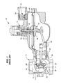
FIG. 1 depicts oneconventional gas regulator 10. Theregulator 10 generally comprises anactuator 12 and aregulator valve 14. Theregulator valve 14 defines aninlet 16, anoutlet 18, and athroat 11. Theinlet 16 is for receiving gas from a gas distribution system, for example. Theoutlet 18 is for delivering gas to an end-user facility such as a factory, a restaurant, an apartment building, etc. having one or more appliances, for example. Additionally, theregulator valve 14 includes avalve port 136 carried by thethroat 11 and disposed between theinlet 16 and theoutlet 18. Gas must pass through thevalve port 136 to travel between theinlet 16 and theoutlet 18 of theregulator valve 14. - The
actuator 12 is coupled to theregulator valve 14 to ensure that the pressure at theoutlet 18 of theregulator valve 14, i.e., the outlet pressure, is in accordance with a desired outlet or control pressure. Theactuator 12 is therefore in fluid communication with theregulator valve 14 via avalve mouth 34 and anactuator mouth 20. Theactuator 12 includes acontrol assembly 22 for sensing and regulating the outlet pressure of theregulator valve 14. Specifically, thecontrol assembly 22 includes adiaphragm 24, apiston 32, and acontrol arm 26 having avalve disc 28. Thevalve disc 28 includes a generallycylindrical body 25 and a sealinginsert 29 fixed to thebody 25. Thediaphragm 24 senses the outlet pressure of theregulator valve 14. Thecontrol assembly 22 further includes acontrol spring 30 in engagement with a top-side of thediaphragm 24 to offset the sensed outlet pressure. Accordingly, the desired outlet pressure, which may also be referred to as the control pressure, is set by the selection of thecontrol spring 30. - The
diaphragm 24 is operably coupled to thecontrol arm 26, and therefore thevalve disc 28, via thepiston 32, and controls the opening of theregulator valve 14 based on the sensed outlet pressure. For example, when an end user operates an appliance, such as a furnace that places a demand on the gas distribution system downstream of theregulator 10, the outlet flow increases, thereby decreasing the outlet pressure. Accordingly, thediaphragm 24 senses this decreased outlet pressure. This allows thecontrol spring 30 to expand and move thepiston 32 and the right-side of thecontrol arm 26 downward, relative to the orientation ofFIG. 1 . This displacement of thecontrol arm 26 moves thevalve disc 28 away from thevalve port 136 to open theregulator valve 14. So configured, the appliance may draw gas through thevalve port 136 toward theoutlet 18 of theregulator valve 14, as demand may be required for operation. -
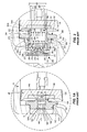
FIG. 1A depicts theconventional valve port 136 of theconventional regulator 10 installed within thethroat 11 of theregulator valve 14 depicted inFIG. 1 . Thevalve port 136 depicted inFIG. 1A includes a one-piece body having avalve seat 138, ahexagonal nut portion 140, and abody portion 142. Thevalve seat 138 protrudes from thenut portion 140 and is adapted to be engaged by thevalve disc 28 to close theregulator valve 14. Thebody portion 142 includes a plurality ofexternal threads 143 in threaded engagement with thethroat 11 of theregulator valve 14. So configured, thevalve port 136 is removable from theregulator valve 14 such that it may be replaced with a different valve port having a different configuration to tailor operational and flow characteristics of theregulator valve 14 to a specific application. - Additionally, the
valve port 136 of the conventional embodiment depicted inFIG. 1A defines anelongated orifice 144 for allowing the passage of gas through theregulator valve 14. Theorifice 144 is a cylindrical bore of substantially uniform diameter D1 including aninlet 144a and anoutlet 144b. Theinlet 144a includes a chamferedinner surface 148. So configured, gas flows through theconventional valve port 136 in accordance with a flow path, which may be indicated byflow arrows 146 inFIG. 1A . More particularly, the flow of gas enters theinlet 144a of theorifice 144 and exits theoutlet 144b. However, due to basic concepts of fluid dynamics such as the boundary layer effect, the flow of the gas follows theflow arrows 146, which, as illustrated, separate from the sidewalls of theorifice 144 toward theoutlet 144b. Thus, theorifice 144 has an effective diameter D2, which is defined by the flow of gas emerging from theoutlet 144b. The effective diameter D2 is less than actual diameter D1. Therefore, the maximum potential flow capacity of theorifice 144 and thevalve port 136 is not realized. -
FIG. 2 depicts an alternativeconventional valve port 236, which is adapted to provide both a primary seal and a secondary, or back-up seal. Thevalve port 236 generally includes ahousing 260, acartridge 262, and aspring 264. Thecartridge 262 is slidably disposed within thehousing 260 and includes aninlet 262a, anoutlet 262b, and anelongated orifice 244. Theorifice 244 is generally cylindrical and includes aninlet portion 244a and anoutlet portion 244b. In the embodiment depicted inFIG. 2 , theinlet portion 244a has a uniform diameter D1 that is slightly larger than a uniform diameter D2 of theoutlet portion 244b. Additionally, in the depicted embodiment, theinlet 262a of thecartridge 262 includes a chamferedinner surface 292. Thespring 264 biases thecartridge 262 into the position depicted inFIG. 2 , which corresponds to thevalve port 236 providing the primary seal, as will be described below. So configured, gas flows through theconventional valve port 236 in accordance with a flow path, which may be indicated byflow arrows 246. More particularly, the flow of gas enters theinlet portion 244a of theorifice 244 and exits theoutlet portion 244b. However, due to basic concepts of fluid dynamics such as boundary layer separation, the flow of the gas follows theflow arrows 246. Specifically, the gas separates from the sidewalls of theorifice 244 as it reaches theoutlet portion 244b of theorifice 244. Thus, theoutlet portion 244a of theorifice 244 has an effective diameter D3, which is defined by the flow of gas emerging from theoutlet portion 244b. The effective diameter D3 is less than the actual diameter D1. Therefore, similar to thevalve port 136 described above with reference toFIG. 1A , the maximum potential flow capacity of theorifice 244 and thevalve port 236 is not completely realized.
Another conventional regulator, similar to what is shown inFIGS 1 ,1A and 2 , is disclosed inUS 4 195 656 . - With continued reference to
FIG. 2 , thehousing 260 includes a hollow, generally cylindrical housing having ahexagonal nut portion 266, abody portion 268, and acurtain portion 270. Thebody portion 268 includes aninternal bore 274 accommodating thecartridge 262. Thebody portion 268 further includes a plurality ofexternal threads 272 for being threadably coupled into thethroat 11 of theregulator valve 14, as depicted. Thenut portion 266 of thehousing 262 is therefore adapted to be engaged by a tool such as a pneumatic ratchet to install thevalve port 236 into thethroat 11 of theregulator valve 14. Thecurtain portion 270 includes aplate 280 spaced from thebody portion 268 of thehousing 262 by a pair oflegs 282. Theplate 280 carries asecondary seat 271 including arubber surface 273, for example. So configured, thecurtain portion 270 defines a pair ofwindows 284 in thehousing 260. Thewindows 284 allow for the flow of gas into thevalve port 236 and through theregulator valve 14. - Accordingly, during a normal operational condition, the
outlet 262b of thecartridge 262 serves as a primary seat and is adapted to be engaged by thevalve disc 28 of thecontrol assembly 22 to stop the flow of fluid through theregulator valve 14. However, in the event that debris or some other type of foreign material becomes lodged between the valve disc 8 and theoutlet 262b of thecartridge 262 when thevalve disc 28 attempts to seal against thecartridge 262, the primary seal fails to stop the flow of gas through thevalve port 236. Thus, the pressure downstream of theregulator 10, i.e., the outlet pressure, increases. This increase in pressure is sensed by thediaphragm 24 which further causes thevalve disc 28 to be forced toward thevalve port 236. This force eventually overcomes the force of thespring 264 and displaces thecartridge 262 into thehousing 260 such that theinlet 262a engages therubber surface 273 of thesecondary seat 271. So configured, thesecondary seat 271 of thehousing 260 seals theinlet 262a and blocks the flow of gas through thewindows 284 in thehousing 260, thereby preventing the flow of gas through thecartridge 262 and theregulator valve 14. - Once a downstream demand is placed back on the system however, the
diaphragm 24 senses a decrease in outlet pressure and moves thevalve disc 28 away from thevalve port 236. Thespring 264 biases thecartridge 262 back to the position depicted inFIG. 2 and any debris previously lodged between thevalve disc 28 and theoutlet 262a of thecartridge 262 releases and flows downstream. - Referring back to
FIG. 1 and as mentioned above, theconventional regulator 10 further functions as a relief valve. Specifically, thecontrol assembly 22 includes arelief spring 40 and arelease valve 42. Thediaphragm 24 includes anopening 44 through a central portion thereof and thepiston 32 includes a sealingcup 38. Therelief spring 40 is disposed between thepiston 32 and thediaphragm 24 to bias thediaphragm 24 against the sealingcup 38 to close theopening 44, during normal operation. Upon the occurrence of a failure such as a break in thecontrol arm 26, for example, thecontrol assembly 22 is no longer in direct control of thevalve disc 28 and the flow through theregulator valve 14 moves thevalve disc 28 into an extreme open position. This allows a maximum amount of gas to flow into theactuator 12. Thus, as the gas fills theactuator 12, pressure builds against thediaphragm 24 forcing thediaphragm 24 away from the sealingcup 38, thereby exposing theopening 44. The gas therefore flows through theopening 44 in thediaphragm 24 and toward therelease valve 42. Therelease valve 42 includes avalve plug 46 and arelease spring 54 biasing thevalve plug 46 into a closed position, as depicted inFIG. 1 . Upon the pressure within theactuator 12 and adjacent therelease valve 42 reaching a predetermined threshold pressure, thevalve plug 46 displaces upward against the bias of therelease spring 54 and opens, thereby exhausting gas into the atmosphere and reducing the pressure in theregulator 10. - One consideration in selecting a regulator for use in a particular application includes maximizing flow capacity at the set outlet, or control, pressure. However, as discussed above, the
orifices conventional valve ports - The present invention provides a regulator and/or a valve port for a regulator. The regulator generally comprises an actuator and a valve body. The actuator includes a moveable valve disc. The valve port is disposed within the valve body. The actuator displaces the valve disc relative to the valve port for controlling the flow of fluid through the valve body. The valve port includes an orifice for allowing the passage of fluid through the valve body.
- One aspect of the valve port may include an orifice including an inlet portion and an outlet portion. The inlet portion may include an inner sidewall that converges from an enlarged inlet aperture toward the outlet portion. So configured, the inlet portion forces the flow of fluid through the valve port to maximize the flow capacity.
- In another aspect of the valve port of the present invention, the inlet portion of the orifice may include a longitudinal dimension substantially greater than a longitudinal dimension of the outlet portion.
- Another aspect of the present invention may further include a valve port comprising a housing and a cartridge slidably disposed within the housing for providing a primary and a secondary seal, wherein the cartridge may define an orifice with an inner sidewall that converges from an enlarged inlet aperture toward an outlet. So configured, the converging sidewall forces the flow of fluid through the valve port to maximize the flow capacity.
-
FIG. 1 is a side cross-sectional view of a conventional regulator including one conventional valve port; -
FIG. 1A is a side cross-sectional view of a regulator valve of the regulator ofFIG. 1 including the conventional valve port ofFIG. 1 and taken from circle 1-A ofFIG. 1 ; -
FIG. 2 is a side cross-sectional view of another conventional valve port adapted for use with the regulator ofFIG. 1 ; -
FIG. 3 is a side cross-sectional view of a regulator including a valve port, the regulator and valve port constructed in accordance with a first embodiment of the present invention; -
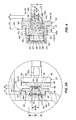
FIG. 3A is a side cross-sectional view of a regulator valve of the regulator ofFIG. 3 illustrating the valve port of the first embodiment of the present invention and taken from circle III-A ofFIG. 3 ; -
FIG. 4 is a side cross-sectional view of a valve port constructed in accordance with a second embodiment of the present invention; and -
FIG. 5 is a side cross-sectional view of a cartridge for use in a valve port constructed in accordance with a third embodiment of the present invention. -
FIG. 3 depicts agas regulator 300 constructed in accordance with one embodiment of the present invention. Thegas regulator 300 generally includes anactuator 302 and aregulator valve 304. Theregulator valve 304 includes aninlet 306 for receiving gas from a gas distribution system, for example, and anoutlet 308 for delivering gas to a facility having one or more appliances, for example. Theactuator 302 is coupled to theregulator valve 304 and includes acontrol assembly 322 having acontrol element 327. During a first or normal operational mode, thecontrol assembly 322 senses the pressure at theoutlet 308 of theregulator valve 304, i.e., the outlet pressure, and controls a position of thecontrol element 327 such that the outlet pressure approximately equals a predetermined control pressure. Additionally, upon the occurrence of a failure in the system such as a breakage of one of the components of thecontrol assembly 322, theregulator 300 performs a relief function that is generally similar to the relief function described above with reference to therelief valve 42 of theregulator 10 depicted inFIG. 1 . - With continued reference to
FIG. 3 , theregulator valve 304 further includes athroat 310 and avalve mouth 312. Thethroat 310 is disposed between theinlet 306 and theoutlet 308 and accommodates avalve port 336. Thevalve mouth 312 defines anopening 314 disposed along an axis that is generally perpendicular to an axis of theinlet 306 andoutlet 308 of theregulator valve 304. Thevalve port 336 includes aninlet end 350, anoutlet end 352, and anelongated orifice 344 extending between theinlet end 350 and theoutlet end 352. Gas must travel through theorifice 344 in thevalve port 336 to travel between theinlet 306 and theoutlet 308 of theregulator valve 304. Thevalve port 336 is removable from theregulator valve 304 such that it may be replaced with a different valve port having a different configuration to tailor operational and flow characteristics of theregulator valve 304 to a specific application. - The
actuator 302 includes ahousing 316 and thecontrol assembly 322, as mentioned above. Thehousing 316 includes anupper housing component 316a and alower housing component 316b secured together with a plurality of fasteners (not shown), for example. Thelower housing component 316b defines acontrol cavity 318 and anactuator mouth 320. Theactuator mouth 320 is connected to thevalve mouth 312 of theregulator valve 304 to provide fluid communication between the actuator 302 and theregulator valve 304. In the disclosed embodiment, theregulator 300 includes acollar 311 securing themouths upper housing component 316a defines arelief cavity 334 and anexhaust port 356. Theupper housing component 316a further defines atower portion 358 for accommodating a portion of thecontrol assembly 322, as will be described. - The
control assembly 322 includes adiaphragm subassembly 321, adisc subassembly 323, and arelief valve 342. Thediaphragm subassembly 321 includes adiaphragm 324. apiston 332, acontrol spring 330, arelief spring 340, acombination spring seat 364, arelief spring seat 366, acontrol spring seat 360, and apiston guide 359. - More particularly, the
diaphragm 324 includes a disc-shaped diaphragm defining anopening 344 through a central portion thereof. Thediaphragm 324 is constructed of a flexible, substantially air-tight, material and its periphery is sealingly secured between the upper andlower housing components housing 316. Thediaphragm 324 therefore separates therelief cavity 334 from thecontrol cavity 318. - The
combination spring seat 364 is disposed on top of thediaphragm 324 and defines anopening 370 positioned concentric with theopening 344 in thediaphragm 324. As depicted inFIG. 3 , thecombination spring seat 364 supports thecontrol spring 330 and therelief spring 340. - The
piston 332 of the disclosed embodiment includes a generally elongated rod-shaped member having a sealingcup portion 338, ayoke 372, a threadedportion 374, and aguide portion 375. The sealingcup portion 338 is concaved and generally disc-shaped and extends circumferentially about a mid-portion of thepiston 332, and is located just below thediaphragm 324. Theyoke 372 includes a cavity adapted to accommodate acoupler 335 which connects to a portion of thedisc subassembly 323 to enable attachment between thediaphragm subassembly 321 and thedisc subassembly 323, as will be described. - The
guide portion 375 and the threadedportion 374 of thepiston 332 are disposed through theopenings diaphragm 324 and thecombination spring seat 364, respectively. Theguide portion 375 of thepiston 332 is slidably disposed in a cavity in thepiston guide 359, which maintains the axial alignment of thepiston 332 relative to the remainder of thecontrol assembly 322. Therelief spring 340, therelief spring seat 366, and anut 376, are disposed on the threadedportion 374 of thepiston 332. Thenut 376 retains therelief spring 340 between thecombination spring seat 364 and therelief spring seat 366. Thecontrol spring 330 is disposed on top of thecombination spring seat 364, as mentioned, and within thetower portion 358 of theupper housing component 316a. Thecontrol spring seat 360 is threaded into thetower portion 358 and compresses thecontrol spring 330 against thecombination spring seat 364. - In the disclosed embodiment, the
control spring 330 and therelief spring 340 include compression coil springs. Accordingly, thecontrol spring 330 is grounded against theupper housing component 316a and applies a downward force to thecombination spring seat 364 and thediaphragm 324. Therelief spring 340 is grounded against thecombination spring seat 364 and applies an upward force to therelief spring seat 366, which in turn is applied to thepiston 332. In the disclosed embodiment, the force generated by thecontrol spring 330 is adjustable by adjusting the position of thecontrol spring seat 360 in thetower portion 358, and therefore the control pressure of theregulator 300 is also adjustable. - The
control spring 330 acts against the pressure in thecontrol cavity 318, which is sensed by thediaphragm 324. As stated, this pressure is the same pressure as that which exists at theoutlet 308 of theregulator valve 304. Accordingly, the force applied by thecontrol spring 330 sets the outlet pressure to a desired, or control pressure for theregulator 300. Thediaphragm subassembly 321 is operably coupled to thedisc subassembly 323, as mentioned above, via theyoke 372 of thepiston 332 and thecoupler 335. - The
disc subassembly 323 includes acontrol arm 326 and astem guide 362. Thecontrol arm 326 includes astem 378, alever 380, and thecontrol element 327. Thecontrol element 327 of the disclosed embodiment includes avalve disc 328 with aseating surface 388. Thestem 378, thelever 380, and thevalve disc 328 are constructed separately and assembled to form thecontrol arm 326. Specifically, thestem 378 is a generally linear rod having anose 378a and arecess 378b, which in the disclosed embodiment is generally rectangular. Thelever 380 is a slightly curved rod and includes afulcrum end 380a and afree end 380b. Thefulcrum end 380a includes anaperture 384 receiving apivot pin 386 carried by thelower housing component 316b. Thefulcrum end 380a also includes aknuckle 387 having an elliptical cross-section and disposed within therecess 378b of thestem 378. Thefree end 380b is received between atop portion 335a and a pin 335b of thecoupler 335 that is attached to theyoke 372 of thepiston 332. Thus, thecoupler 335 operably connects thedisc subassembly 323 to thediaphragm subassembly 321. - The
stem guide 362 includes a generally cylindricalouter portion 362a, a generally cylindricalinner portion 362b, and a plurality ofradial webs 362c connecting the inner andouter portions outer portion 362a of thestem guide 362 is sized and configured to fit within themouths regulator valve 304 andlower housing component 316b. Theinner portion 362b is sized and configured to slidably retain thestem portion 378 of thecontrol arm 326. Thus, thestem guide 362 serves to maintain the alignment of theregulator valve 304, theactuator housing 316, and thecontrol assembly 322, and more particularly, thestem 378 of thecontrol arm 326 of thecontrol assembly 322. -
FIG. 3 depicts thecontrol assembly 322 in a normally operational closed position, where there is no demand placed on the system downstream of theregulator 300. Therefore, theseating surface 388 of thevalve disc 328 sealingly engages theoutlet end 352 of thevalve port 336. So configured, gas does not flow through thevalve port 336. This configuration is achieved because the outlet pressure, which corresponds to the pressure in thecontrol cavity 318 of thehousing 316 and sensed by thediaphragm 324, is greater than the force applied by thecontrol spring 330. Accordingly, the outlet pressure forces thediaphragm 324, thepiston 332, and thevalve disc 328 into the closed position depicted. - However, in the event that an operating demand is placed on the system, e.g., a user begins operating an appliance such as a furnace, a stove, etc., the appliance draws gas from the
control cavity 318 of theregulator 300, thereby reducing the pressure that is sensed by thediaphragm 324. As the pressure sensed by thediaphragm 324 decreases, a force imbalance occurs between a control spring force and an outlet pressure force on thediaphragm 324 such that thecontrol spring 330 expands and displaces thediaphragm 324 andpiston 332 downward, relative to thehousing 316. This causes thelever 380 to pivot in the clockwise direction about thepivot pin 386, which, in turn, rotates theknuckle 387 relative to therecess 378b in thestem 378. This moves thevalve disc 328 away from theoutlet end 352 of thevalve port 336 to open theregulator valve 304. So configured, the gas distribution system is able to deliver gas to the downstream appliance through theregulator valve 304 at a control pressure that is set by thecontrol spring 330. Additionally, thediaphragm subassembly 321 continues to sense the outlet pressure of theregulator valve 304. As long as the outlet pressure remains approximately equal to the control pressure, thecontrol assembly 322 will balance thevalve disc 328 in an open position away from theoutlet end 352 of thevalve port 336. - For example, if the outlet flow increases, i.e., the demand increases, the outlet pressure will decrease below the control pressure. The diaphragm senses the decrease in outlet pressure and the
spring 330 expands and moves thediaphragm 324 andpiston 332 downward to move thevalve disc 328 away from thevalve port 336 and further open theregulator valve 304. Alternatively, however, if the outlet flow decreases, i.e., the demand decreases, the outlet pressure will increase above the control pressure set by thecontrol spring 330. Therefore, thediaphragm 324 senses the increased outlet pressure and moves upward against the bias of thecontrol spring 330 to move thevalve disc 328 back toward thevalve port 336. Accordingly, in the event that the downstream demand completely stops, gas will continue to flow through theregulator valve 304 and increase the downstream pressure sufficiently to move thevalve disc 328 into engagement with theoutlet end 352 of thevalve port 336, as depicted. -
FIG. 3A depicts thevalve port 336 ofFIG. 3 , which is constructed in accordance with one embodiment of the present invention. Thevalve port 336 includes a one-piece body similar to theconventional valve port 136 described above with reference toFIG. 1A . Thevalve port 336 includes avalve seat 338, ahexagonal nut portion 340, and abody portion 342. Thevalve seat 338 protrudes from thenut portion 340 and is adapted to be engaged by theseating surface 388 of thevalve disc 328 to close theregulator valve 304 and prevent the flow of gas through theregulator 300, as depicted inFIG. 3 . Thebody portion 342 includes a plurality ofexternal threads 343 in threaded engagement with thethroat 310 of theregulator valve 304. Thehexagonal nut portion 340 is adapted to be engaged by a tool such as a pneumatic ratchet, for example, to install thevalve port 336 into theregulator valve 304. Additionally, as depicted, thevalve port 336 defines theelongated orifice 344 for allowing the passage of gas through theregulator valve 304, as mentioned above. Accordingly, thevalve port 336 is removable from theregulator valve 304 such that it may be replaced with a different valve port having a different configuration to tailor operational and flow characteristics of theregulator valve 304 to a specific application. - The
orifice 344 of thevalve port 336 of the embodiment depicted inFIG. 3A defines aninlet aperture 347, atransition aperture 349, an outlet aperture 351, aninlet portion 344a, and anoutlet portion 344b. Theinlet aperture 347 is disposed proximate to theinlet end 350 of thevalve port 336 and the outlet aperture 351 is disposed proximate to theoutlet end 352 of thevalve port 336. Theinlet portion 344a extends between theinlet aperture 347 and thetransition aperture 349. Theoutlet portion 344b extends between thetransition aperture 349 and the outlet aperture 351. In the disclosed embodiment, the inlet, transition, andoutlet apertures outlet apertures 349, 351 have a common diameter D1. Therefore, theoutlet portion 344b of theorifice 344 includes a generally uniform diameter D1 that is equal to the diameter D1 of the transition andoutlet apertures 349, 351. - The
inlet aperture 347 of the disclosed embodiment, however, has a diameter D2 that is larger than the diameter D1 of the transition andoutlet apertures 349, 351. Therefore, theinlet portion 344a of the disclosed embodiment includes asidewall 345 that generally uniformly converges from theinlet aperture 347 to thetransition aperture 349. Therefore, in one embodiment, thesidewall 335 of theinlet portion 344a can be a frustoconical, or a tapered, sidewall. In the disclosed embodiment, thesidewall 345 may converge at an angle α that is between approximately 15° and approximately 75°, and at least in one embodiment, approximately 45°. - Additionally, in the disclosed embodiment, the diameter D2 of the
inlet aperture 347 may be between approximately 10% and approximately 150% larger than the diameter D 1 of the transition andoutlet apertures 349, 351. Further still, theinlet portion 344a of the disclosed embodiment constitutes a majority of the length of theorifice 344. For example, theinlet portion 344a includes a longitudinal dimension L1 that is larger than a longitudinal dimension L2 of theoutlet portion 344b. In one embodiment, the longitudinal dimension L1 of theinlet portion 344a may be between approximately 10% and approximately 150% larger than the longitudinal dimension of theoutlet portion 344b, and at least in one embodiment, approximately 100% larger. - In alternative embodiments, however, the diameters of the inlet, transition, and
outlet apertures outlet portions inlet portion 344a may be equal to or smaller than the longitudinal dimension L2 of theoutlet portion 344b. Regardless of the specific arrangement, theorifice 344 of the present embodiment maximizes the flow capacity of thevalve port 336 by minimizing the detrimental effects of basic fluid dynamics such as boundary layer fluid separation. - For example, the
valve port 336 of the present embodiment advantageously directs gas flowing through theregulator valve 304 along a flow path, which may be indicated byflow arrows 346 inFIG. 3A . More particularly, the flow of gas enters the increased diameter D2 of theinlet aperture 347 of theorifice 344. As the gas flows through theinlet portion 344a, theconvergent sidewall 345 directs the gas to conform with the dimensions of thetransition aperture 349 and theoutlet portion 344b of theorifice 344. This direction advantageously increases the pressure of the gas within theoutlet portion 344b and thereby reduces the effects of boundary layer fluid separation adjacent to the sidewalls of theoutlet portion 344b and maximizes the capacity of thevalve port 336. Accordingly, thevalve port 336 of the present embodiment includes an effective diameter D3, which is defined by the diameter of the flow of gas emerging from theoutlet portion 344b of theorifice 344. The effective diameter D3 is substantially equal to the diameter D1 of theoutlet portion 344b and the full potential of the flow capacity of thevalve port 336 is approximately realized. -
FIG. 4 depicts another embodiment of avalve port 436 constructed in accordance with the principles of the present invention for being installed within thethroat 310 of theregulator valve 304 ofFIG. 3 . Thevalve port 436 depicted inFIG. 4 is similar to theconventional valve port 236 described above with reference toFIG. 2 in that it is configured to provide a primary seal and a secondary, or back-up, seal. Thevalve port 436 generally includes ahousing 460, acartridge 462, and aspring 464. Thecartridge 462 is slidably disposed within thehousing 460 and includes aninlet end 462a, anoutlet end 462b, and anelongated orifice 444 extending between theinlet end 462a and theoutlet end 462b. Thespring 464 biases thecartridge 462 into a first position depicted inFIG. 4 , which corresponds to a position for providing the primary seal. - The
housing 460 includes a generally cylindrical housing having ahexagonal nut portion 466, abody portion 468, and acurtain portion 470. Thenut portion 466 and thebody portion 468 cooperatively, or in combination, define aninternal cavity 474 accommodating thecartridge 462. Generally, thecavity 474 includes afirst portion 474a and asecond portion 474b. The diameter of thefirst portion 474a is smaller than the diameter of thesecond portion 474b in the embodiment of thevalve port 436 depicted inFIG. 4 . Additionally, thebody portion 468 includes a plurality ofexternal threads 472 for being threadably coupled into thethroat 310 of theregulator valve 304. Thenut portion 466 of thehousing 460 is therefore adapted to be engaged by a tool such as a pneumatic ratchet to install thevalve port 436 into theregulator valve 304. Accordingly, thevalve port 436 is removable from theregulator valve 304 such that it may be replaced with a different valve port having a different configuration to tailor operational flow characteristics of theregulator valve 304 to a specific application. - The
first portion 474a of thecavity 474 slidably accommodates theinlet end 462a of thecartridge 462, and thesecond portion 474b slidably accommodates theoulet end 462b of thecartridge 462, as depicted. Astep 476 disposed between the first andsecond portions cartridge 462 away from thecurtain portion 470 of thehousing 460. Thecurtain portion 470 includes aplate 480 spaced from thebody portion 468 of thehousing 460 by a pair oflegs 482, only one of which is depicted inFIG. 4 due to the cross-sectional nature of the illustration. Theplate 480 of the disclosed embodiment includes a solid circular plate that serves as aspring seat 471. So configured, thecurtain portion 470 defines a pair ofwindows 484 in thehousing 460 for allowing gas to flow into thevalve port 436. - As mentioned, the
cartridge 462 includes aninlet end 462a, anoutlet end 462b, and anelongated orifice 444 extending between theinlet end 462a and theoutlet end 462b. Theorifice 444 defines a receivingaperture 445, aninlet aperture 447, atransition aperture 449, and an outlet aperture 451. The receiving andinlet apertures inlet end 462a of thecartridge 462, and the transition andoutlet apertures 449, 451 are disposed proximate to theoutlet end 462b of thecartridge 462. So configured, theorifice 444 includes a receivingportion 444a, aninlet portion 444b, and anoutlet portion 444c. The receivingaperture 445 is disposed adjacent to theinlet end 462a of the valve port. The outlet aperture 451 is disposed adjacent to theoutlet end 462b of thevalve port 436. In the disclosed embodiment, each of theapertures transition apertures 451, 449 share a common diameter D1. Theinlet aperture 447 has a diameter D2. The receivingaperture 445 has a diameter D3. In the disclosed embodiment, the diameter D2 of theinlet aperture 447 is larger than the diameter D1 of both the outlet andtransition apertures 451, 449. Additionally, the diameter D3 of the receivingaperture 445 is larger than the diameter D2 of theinlet aperture 447. - The receiving
portion 444a is generally uniformly cylindrical and extends between the receivingaperture 445 and theinlet aperture 447. Additionally, the receivingportion 444c of the disclosed embodiment defines a chamferedinner surface 492 disposed adjacent to the receivingaperture 445. Similarly, theoutlet portion 444c extends between thetransition aperture 449 and the outlet aperture 451, and therefore, is also generally cylindrical. Theinlet portion 444b extends between theinlet aperture 447 and thetransition aperture 449. As mentioned above, the diameter D2 of theinlet aperture 447 is larger than the diameter D1 of thetransition aperture 449, and therefore, theinlet portion 444b of theorifice 444 includes asidewall 435 that converges from theinlet aperture 447 toward thetransition aperture 449. In the disclosed embodiment, theinlet portion 444b generally uniformly converges at an angle β of between approximately 15° and approximately 85°, and at least in one embodiment, approximately 75°. In one embodiment, thesidewall 435 of theinlet portion 444b can be frustoconical, or generally tapered, for example. Furthermore, in the disclosed embodiment, the diameter D2 of theinlet aperture 447 may be between approximately 10% and approximately 150% larger than the diameter D1 of thetransition aperture 449. However, alternative embodiments may not be limited to such a range of relative dimensions and/or angles. - Further still, as depicted in
FIG. 4 , theinlet portion 444b of theorifice 444 includes a longitudinal dimension L1 that is larger than a longitudinal dimension L2 of theoutlet portion 444c. In one embodiment, the longitudinal dimension L1 of theinlet portion 444b may be between approximately 10% and approximately 150% larger than the longitudinal dimension L2 of theoutlet portion 444c, and at least in one embodiment, approximately 100% larger. However, alternative embodiments may be configured such that the longitudinal dimension L1 of theinlet portion 444b may be equal to or smaller than a longitudinal dimension L2 of theoutlet portion 444c. Regardless of the specific arrangement, theorifice 444 of the embodiment of thevalve port 436 disclosed inFIG. 4 maximizes flow capacity through thecartridge 462 by minimizing the effects of boundary layer fluid dynamics. - For example, similar to that which was described above with reference to the
valve port 336 depicted inFIG. 3 , thevalve port 436 of the present embodiment advantageously directs gas flowing through theregulator valve 304 along a flow path, which may be indicated byflow arrows 446 inFIG. 4 . More particularly, the flow of gas enters the receivingportion 444a of theorifice 444 of thecartridge 462, the diameter D3 of which is larger than the diameter of the remainder of theorifice 444, in the disclosed embodiment. As the gas flows through the receivingportion 444a, it is directed into theinlet portion 444b, via theinlet aperture 447. Theconvergent sidewall 435 of theinlet portion 444b directs the gas to closely conform to the dimensions of thetransition aperture 449 and theoutlet portion 444c of theorifice 444. This direction advantageously increases the pressure of the gas flowing through theoutlet portion 444c and thereby reduces the effects of boundary layer fluid separation adjacent to the sidewalls of theoutlet portion 444c and maximizes the capacity of thevalve port 436. - Accordingly, the
valve port 436 of the present embodiment includes an effective diameter D4, which is defined by the diameter of the flow of gas emerging from theoutlet portion 444b of theorifice 444. The effective diameter D4 is substantially equal to the diameter D1 of the transition andoutlet apertures 449, 451 and theoutlet portion 444c of theorifice 444. - Similar to the
conventional valve port 236 described above with reference toFIG. 2 , during a normal operational condition, theoutlet end 462b of thecartridge 462 serves as a primary seat and is adapted to be engaged by thevalve disc 328 of thecontrol assembly 322 depicted inFIG. 3 , for example, to stop the flow of fluid through theregulator valve 304. However, in the event that debris or some other type of foreign material becomes lodged between thevalve disc 328 and theoutlet end 462b of thecartridge 462, the primary seal fails to stop the flow of gas through thevalve port 436. Thus, gas continues to flow through theregulator valve 304 and the pressure downstream of theregulator 10, i.e., the outlet pressure, increases. This increase in pressure is sensed by thediaphragm 324 which further causes thevalve disc 328 to be forced toward thevalve port 436. This force eventually overcomes the force of thespring 464 and displaces thecartridge 462 into thehousing 460 such that theinlet end 462a engages thesecondary seat 471. So configured, thesecondary seat 471 of thehousing 460 seals theinlet end 462a and blocks the flow of gas through thewindows 484 in thehousing 460, thereby preventing the flow of gas through theorifice 444 in thecartridge 462 and theregulator valve 304. - Once a downstream demand is placed back on the system however, the
diaphragm 324 senses a decrease in outlet pressure and moves thevalve disc 328 away from thevalve port 436. Thespring 464 biases thecartridge 462 back to the position depicted inFIG. 4 and any debris previously lodged between thevalve disc 328 and theoutlet end 462a of thecartridge 462 releases and flows downstream. - In light of the foregoing, it should be appreciated that the present invention provides a
valve port orifice valve port valve ports orifices FIG. 5 depicts analternative cartridge 562 adapted for use with thevalve port 436 described above with reference toFIG. 4 . - Similar to the
cartridge 462 described above, thecartridge 562 depicted inFIG. 5 includes aninlet end 562a, anoutlet end 562b, and anelongated orifice 544 extending between theinlet end 562a and theoutlet end 562b. Theorifice 544 defines a receivingaperture 545, afirst transition aperture 547a, aninlet aperture 549, asecond transition aperture 547b, and anoutlet aperture 551. The receiving, first transition, andinlet apertures cartridge 562, when compared to the second transition andoutlet apertures outlet end 562b of thecartridge 562. Additionally, theorifice 544 includes a receivingportion 544a, atransition portion 544b, aninlet portion 544c, and anoutlet portion 544d. The receivingportion 544a of the embodiment of thecartridge 562 depicted inFIG. 5 also includes an innerchamfered surface 592 disposed adjacent to the receivingaperture 545. - Each of the
apertures outlet aperture 551 and thesecond transition aperture 547b share a common diameter D1. Theinlet aperture 549 and thefirst transition aperture 547a have a common diameter D2. The receivingaperture 545 has a diameter D3. In the disclosed embodiment, the diameter D2 of theinlet aperture 549 is larger than the diameter D1 of theoutlet aperture 551 and thesecond transition aperture 547b. Additionally, the diameter D3 of the receivingaperture 545 is larger than the diameter D2 of theinlet aperture 549. - The receiving
portion 544a of theorifice 544 is generally uniformly cylindrical and extends between the receivingaperture 545 and thefirst transition aperture 547a. Similarly, thetransition portion 544b of theorifice 544 is generally uniformly cylindrical and extends between thefirst transition aperture 547a and theinlet aperture 549. Moreover, theoutlet portion 544d of the orifice extends between thesecond transition aperture 547b and theoutlet aperture 551, and therefore, is also generally cylindrical. - In contrast, the
inlet portion 544c extends between theinlet aperture 549 and thesecond transition aperture 547b. As stated above, the diameter D1 of thesecond transition aperture 547b is smaller than the diameter D2 of theinlet aperture 549. Accordingly, theinlet portion 544c includes asidewall 535 that generally uniformly converges from theinlet aperture 549 toward thesecond transition aperture 547b. Therefore, in the disclosed embodiment, thesidewall 535 of theinlet portion 544c can be considered a frustoconical, or tapered, sidewall that converged at an angle ϕ of between approximately 15° and approximately 85°, and at least in one embodiment, approximately 45°. Furthermore, in one embodiment, the diameter D2 of theinlet aperture 549 may be between approximately 10% and approximately 150% larger than the diameter D1 of thesecond transition aperture 547b and theoutlet portion 544d of theorifice 544, and at least in one embodiment, approximately 50% larger. However, alternative embodiments may not be limited to such a range of relative dimensions and/or angles. - Further still, as depicted in
FIG. 5 , a longitudinal dimension L1 of thetransition portion 544b and theinlet portion 544c combined is larger than a longitudinal dimension L2 of theoutlet portion 544d. In one embodiment, the longitudinal dimension L 1 may be between approximately 10% and approximately 300% larger than the longitudinal dimension L2, and at least in one embodiment, approximately 200% larger. However, alternative embodiments may be configured such that the longitudinal dimension L1 may be equal to or smaller than the longitudinal dimension L2. Regardless of the specific arrangement, theorifice 544 of the embodiment of the cartridge 563 disclosed inFIG. 5 provides the same advantages as thecartridge 462 depicted inFIG. 4 . - Specifically, the
cartridge 562 of the present embodiment includes an effective diameter D4, which is defined by the diameter of the flow of gas emerging from theoutlet portion 544d of theorifice 544. The effective diameter D4 is substantially equal to the diameter D1 of theoutlet aperture 551 and theoutlet portion 544d of theorifice 544. Accordingly, theorifice 544 of the present embodiment advantageously maximizes the flow capacity of thecartridge 562 by offsetting the effects of boundary layer fluid separation otherwise present in conventional valve ports. - As stated above, the present invention is not intended to be limited to the examples provided herein. Alternative embodiments may include additional features to help increase flow capacity or other performance characteristics of a valve port constructed in accordance with the principles of the present invention. For example, one alternative embodiment of the
valve port 336 described above with reference toFIG. 3A may include a bull-nosed, or rounded, transition between theinlet portion 344a and theoutlet portion 344b of theorifice 344. Such a bull-nosed transition may further assist the valve body in decreasing the effects of boundary layer separation. The same concept could also be applied to any of the transitions between the different portions of theorifices cartridges FIGS. 4 and5 . - Furthermore, while the
cartridges inner surface apertures inner surfaces inner surfaces FIG. 5 , for example, that is between approximately 5° and approximately 75°, and at least in one embodiment approximately 30°. Still further embodiments may include chamfered inner surfaces that do not fall within this prescribed range of angles. - Further yet, while the
valve ports orifices - Finally, while the various converging
inlet portions frustoconical sidewalls inlet portions - Thus, the regulators and valve ports described herein are merely examples of fluid control devices incorporating the principles of the present invention. Other fluid control devices such as control valves may also benefit from the structures and/or advantages of the present invention.
Claims (8)
- A fluid regulating device (300) comprising:a valve body (304) having a valve body inlet (306), a valve body outlet (308), and a throat (310) disposed between the valve body inlet (306) and the valve body outlet (308);a control element (327) disposed within the valve body (304) and adapted to be displaced between an open position and a closed position for controlling the flow of fluid through the valve body (304);an actuator (302) coupled to the valve body (304) and including a diaphragm (321) operably coupled to the control element (327), the diaphragm (321) responsive to a pressure at the valve body outlet (308) for moving the control element (327) between the open and closed positions; anda valve port (336) carried by the throat (310) of the valve body (304) and comprising a primary valve seat (338) adapted to be engaged by the control element (327) when the control element is in the closed position to prevent the flow of fluid through the valve body (304), the valve port (336) further comprising:an inlet aperture (347) which is disposed proximate to an inlet end (350) of the valve port (336), an outlet aperture (351) which is disposed proximate to an outlet end (352) of the valve port (336), a transition aperture (349), and an elongated orifice (344) extending between the inlet aperture (347) and the outlet aperture (351) and defining an inlet portion (344a) and an outlet portion (344b), wherein the inlet portion (344a) extends between the inlet aperture (347) and the transition aperture (349) and the outlet portion (344b) extends between the transition aperture (349) and the output aperture (351), and wherein the transition aperture (349) and the outlet aperture (351) have a common diameter (D1);
characterized in thatthe elongated orifice (344) comprising a frustoconical portion which is defined by a sidewall (345) of the inlet portion (344a) which substantially uniformly converges from the inlet aperture (347) to the transition aperture (349), thereby enabling fluid to flow through the valve port in a manner that reduces boundary layer separation and maximizes flow capacity, and in thata longitudinal dimension (L1) of the inlet portion (344a) is larger than a longitudinal dimension (L2) of the outlet portion (344b), such that the frustoconical portion comprises a majority of the elongated orifice. - The device of claim 1, wherein the frustoconical portion converges at an angle in the range of approximately 15° to approximately 85°.
- The device of claim 1, wherein the inlet aperture (347) having a first diameter that is larger than a second diameter of the outlet aperture (351).
- The device of claim 3, wherein the first diameter is in the range of approximately 10% to approximately 150% larger then the second diameter.
- The device of claim 1, wherein the valve port (336) is threadably connected to the throat (310) of the valve body (304).
- The device of claim 1, wherein the valve port (336) comprises a housing (460) and a cartridge (462) slidably disposed in the housing (460), the cartridge defining the primary valve seat, the elongated orifice (444), the valve port inlet (462a), and the valve port outlet (462b).
- The device of claim 6, wherein the housing (460) comprises a secondary valve seat disposed opposite the cartridge from the primary valve seat and the cartridge (462) is slidably disposed in the housing (460) between a primary seating position where the valve port inlet is spaced from the secondary valve seat, and a secondary seating position where the valve port inlet sealingly engages the secondary valve seat.
- The device of claim 7, wherein the housing (460) further comprises at least one window disposed adjacent the secondary seat for allowing the passage of fluid into the elongated orifice (444) when the cartridge (462) is in the primary seating position.
Priority Applications (1)
| Application Number | Priority Date | Filing Date | Title |
|---|---|---|---|
| EP20120158736 EP2463740B1 (en) | 2007-04-20 | 2008-04-18 | Improved flow valve port for a gas regulator |
Applications Claiming Priority (2)
| Application Number | Priority Date | Filing Date | Title |
|---|---|---|---|
| US91312307P | 2007-04-20 | 2007-04-20 | |
| PCT/US2008/060860 WO2008131248A1 (en) | 2007-04-20 | 2008-04-18 | Improved flow valve port for a gas regulator |
Related Child Applications (1)
| Application Number | Title | Priority Date | Filing Date |
|---|---|---|---|
| EP20120158736 Division EP2463740B1 (en) | 2007-04-20 | 2008-04-18 | Improved flow valve port for a gas regulator |
Publications (2)
| Publication Number | Publication Date |
|---|---|
| EP2140328A1 EP2140328A1 (en) | 2010-01-06 |
| EP2140328B1 true EP2140328B1 (en) | 2012-03-21 |
Family
ID=39619228
Family Applications (2)
| Application Number | Title | Priority Date | Filing Date |
|---|---|---|---|
| EP20080746299 Active EP2140328B1 (en) | 2007-04-20 | 2008-04-18 | Improved flow valve port for a gas regulator |
| EP20120158736 Active EP2463740B1 (en) | 2007-04-20 | 2008-04-18 | Improved flow valve port for a gas regulator |
Family Applications After (1)
| Application Number | Title | Priority Date | Filing Date |
|---|---|---|---|
| EP20120158736 Active EP2463740B1 (en) | 2007-04-20 | 2008-04-18 | Improved flow valve port for a gas regulator |
Country Status (11)
| Country | Link |
|---|---|
| US (1) | US20080257424A1 (en) |
| EP (2) | EP2140328B1 (en) |
| JP (1) | JP5285063B2 (en) |
| CN (2) | CN105179793B (en) |
| AR (1) | AR066141A1 (en) |
| AT (1) | ATE550704T1 (en) |
| AU (1) | AU2008242692B2 (en) |
| BR (1) | BRPI0810027B1 (en) |
| CA (1) | CA2683022C (en) |
| RU (1) | RU2488873C2 (en) |
| WO (1) | WO2008131248A1 (en) |
Families Citing this family (6)
| Publication number | Priority date | Publication date | Assignee | Title |
|---|---|---|---|---|
| US8336574B2 (en) * | 2007-04-20 | 2012-12-25 | Fisher Controls International Llc | Pressure averaging sense tube for gas regulator |
| US9709998B2 (en) | 2013-03-14 | 2017-07-18 | Marshall Excelsior Co. | Pressure regulator |
| IT201600079425A1 (en) * | 2016-07-28 | 2018-01-28 | Pietro Fiorentini Spa | CALIBRATION DEVICE FOR A GAS PRESSURE REGULATOR, IN PARTICULAR FOR A PILOT, AND A PRESSURE ADJUSTMENT SYSTEM FOR A GAS INCLUDING SUCH A CALIBRATION DEVICE |
| US10378657B2 (en) * | 2017-03-24 | 2019-08-13 | Emerson Process Management Regulator Technologies, Inc. | Valve plug assembly and seat ring for regulator |
| EP3715105B1 (en) * | 2019-03-27 | 2023-04-05 | Albéa Services | Laminated material for forming a flexible container and flexible tube skirt comprising said laminated material |
| US11022988B1 (en) * | 2019-11-26 | 2021-06-01 | Emerson Process Management Regulator Technologies, Inc. | Flow limiter for regulators |
Family Cites Families (74)
| Publication number | Priority date | Publication date | Assignee | Title |
|---|---|---|---|---|
| US836258A (en) * | 1906-02-19 | 1906-11-20 | Josef Huebner | Reducing-valve. |
| US1166027A (en) * | 1915-08-18 | 1915-12-28 | Equitable Meter Company | Pressure-regulator. |
| US1262225A (en) * | 1917-04-13 | 1918-04-09 | Frank J Meyer | Gas-regulator. |
| US1918602A (en) * | 1931-02-28 | 1933-07-18 | Roy E Joyce | House service gas regulator |
| US1973744A (en) * | 1933-11-21 | 1934-09-18 | Luther E Brown | Relief valve |
| US2215419A (en) * | 1936-03-20 | 1940-09-17 | Sprague Meter Company | Gas regulator |
| US2192327A (en) * | 1936-06-27 | 1940-03-05 | Garnet W Mckee | Regulator |
| US2173707A (en) * | 1937-11-27 | 1939-09-19 | Continental Screw Company | Square socket screw with side slots |
| US2263581A (en) * | 1940-01-22 | 1941-11-25 | Reynolds Gas Regulator Company | Gas regulator |
| US2315370A (en) * | 1940-07-31 | 1943-03-30 | Reynolds Gas Regulator Co | Fluid pressure regulator |
| US2827069A (en) * | 1951-11-06 | 1958-03-18 | Universal Controls Corp | Gas pressure regulator with internal relief valve |
| US2826213A (en) * | 1951-12-29 | 1958-03-11 | Fisher Governor Co | Gas control valve |
| US2619983A (en) * | 1952-01-04 | 1952-12-02 | Fisher Governor Co | Universal diaphragm valve |
| US2869575A (en) * | 1954-06-09 | 1959-01-20 | Francis G Hutchens | Fluid pressure regulator |
| US2895501A (en) * | 1955-07-18 | 1959-07-21 | Fisher Governor Co | Pressure regulator construction |
| US2951494A (en) * | 1955-07-25 | 1960-09-06 | Bendix Corp | Pressure regulating valve |
| US3001545A (en) * | 1958-10-22 | 1961-09-26 | Manning Maxwell & Moore Inc | Spring loaded pop-action safety valves |
| US3160169A (en) * | 1961-07-17 | 1964-12-08 | Universal Controls Corp | Check valve unit for a diaphragm type pressure regulator |
| FR1393971A (en) * | 1962-01-24 | 1965-04-02 | Clesse S A Ets | Gas regulator that can act as a valve |
| US3228417A (en) * | 1963-08-13 | 1966-01-11 | American Meter Co | Pressure regulator with high pressure cut off |
| US3386465A (en) * | 1965-11-22 | 1968-06-04 | American Meter Co | Pressure regulator with internal low pressure shutoff |
| US3425442A (en) * | 1965-11-24 | 1969-02-04 | American Meter Co | Pressure regulator |
| US3392749A (en) * | 1966-08-18 | 1968-07-16 | American Meter Co | Pressure regulator with balancing piston |
| US3488685A (en) * | 1968-09-17 | 1970-01-06 | Textron Inc | Safety valve for regulators |
| US3525356A (en) * | 1968-10-18 | 1970-08-25 | Dwight N Johnson | Pressure regulator |
| US3580271A (en) * | 1968-12-13 | 1971-05-25 | Bryan Donkin Co Ltd | Gas pressure regulators |
| US3572372A (en) * | 1969-07-14 | 1971-03-23 | Sage Fabricating Inc | Adjustable safety relief valve |
| US3599658A (en) * | 1969-07-28 | 1971-08-17 | American Meter Co | Pressure regulator with internal relief valve |
| US3623506A (en) * | 1969-09-22 | 1971-11-30 | Rockwell Mfg Co | Service regulator with high-low pressure cutoff device |
| US3613725A (en) * | 1970-01-09 | 1971-10-19 | Textron Inc | Safety control for fluid pressure regulators |
| US3705599A (en) * | 1970-07-29 | 1972-12-12 | Marvin L Sheward | Universally-mountable gas service regulator |
| US3722536A (en) * | 1971-12-17 | 1973-03-27 | Singer Co | Monitor pressure regulator assembly |
| US3754570A (en) * | 1972-06-20 | 1973-08-28 | Textron Inc | Safety control for fluid pressure regulators |
| US3809108A (en) * | 1973-04-16 | 1974-05-07 | Textron Inc | Monitor and automatic shutoff for gas regulators |
| US3892255A (en) * | 1973-12-19 | 1975-07-01 | Singer Co | Inlet orifice device to control thruput flow for pressure regulators |
| US4019531A (en) * | 1974-12-20 | 1977-04-26 | The Singer Company | Inlet orifice device to control thruput flow for pressure regulators |
| US3971410A (en) * | 1975-03-05 | 1976-07-27 | Textron, Inc. | Gas pressure regulator having low pressure shut-off means |
| US4067355A (en) * | 1976-04-26 | 1978-01-10 | Textron Inc. | Gas pressure regulator having high and low pressure shut-off means |
| US4069839A (en) * | 1976-05-14 | 1978-01-24 | Textron Inc. | Gas pressure regulator |
| US4067354A (en) * | 1976-07-19 | 1978-01-10 | Textron Inc. | Gas pressure regulator having high and low pressure shutoff means |
| US4129145A (en) * | 1977-05-26 | 1978-12-12 | Wynn James M | Check valve assembly |
| US4176677A (en) * | 1977-12-09 | 1979-12-04 | Textron Inc. | Relay pilot regulator |
| US4195656A (en) * | 1978-07-07 | 1980-04-01 | The Singer Company | Orifice device with safety shut-off for pressure regulators |
| US4485843A (en) * | 1981-05-05 | 1984-12-04 | Wolff Robert C | Variable pressure relief and control valve |
| DE3238059A1 (en) * | 1982-10-14 | 1984-04-19 | Claudius Peters Ag, 2000 Hamburg | SHUT-OFF ARRANGEMENT FOR A CONVEYOR PIPE FOR LUBRICATING, SOLIDS CONTAINING SOLIDS |
| JPH0426891Y2 (en) * | 1985-04-24 | 1992-06-29 | ||
| US4679592A (en) * | 1985-10-07 | 1987-07-14 | Teledyne Industries, Inc. | Valve seat design to reduce cavitation |
| JPS63193212A (en) * | 1987-02-06 | 1988-08-10 | Daikin Ind Ltd | Flow rate regulating valve |
| FR2610071B1 (en) * | 1987-01-26 | 1989-05-12 | Jaeger | VALVE IN PARTICULAR FOR DEGASSING FUEL TANKS OF MOTOR VEHICLES |
| DE3714065A1 (en) * | 1987-04-28 | 1987-10-08 | Gok Gmbh & Co Kg | Gas pressure control combination for adjustable output pressures |
| US4754778A (en) * | 1987-05-26 | 1988-07-05 | Fisher Controls International, Inc. | Velocity boost body with wrap-around pitot tube |
| US4972871A (en) * | 1988-02-29 | 1990-11-27 | Fisher Controls International, Inc. | Boost modified, droop compensated direct acting pressure regulator |
| US4842013A (en) * | 1988-02-29 | 1989-06-27 | Fisher Controls International, Inc. | Droop compensated direct acting pressure regulator |
| CN2057255U (en) * | 1988-04-12 | 1990-05-16 | 王正富 | Indicating pressure regulator for liquefied petroleum |
| US4889158A (en) * | 1988-08-26 | 1989-12-26 | Fisher Controls International, Inc. | Pressure/flow compensated direct acting pressure regulator |
| JPH0750612Y2 (en) * | 1989-03-16 | 1995-11-15 | 株式会社小松製作所 | Pressure control valve |
| DE3933025A1 (en) * | 1989-09-30 | 1991-04-11 | Wiest Peter P | DEVICE FOR MEASURING A PATIENT'S URINE FLOW (UROFLOW) |
| US4972868A (en) * | 1990-02-08 | 1990-11-27 | Fisher Controls International, Inc. | Flow restrictor and diverter for direct acting pressure regulator |
| CN2085977U (en) * | 1991-03-11 | 1991-10-02 | 杨方平 | High-efficient energy-saving voltage regulator |
| JPH0543207U (en) * | 1991-11-15 | 1993-06-11 | 山武ハネウエル株式会社 | Controller |
| US5697398A (en) * | 1995-08-08 | 1997-12-16 | Fisher Controls International, Inc. | Fluid pressure regulator with boost tube unit including stem guide and lever retainer |
| RU2092890C1 (en) * | 1996-02-05 | 1997-10-10 | Фирма "Медлайф компани" | Gas pressure regulator |
| US5881765A (en) * | 1997-03-28 | 1999-03-16 | S. H. Leggitt Company | Direct-acting boost-enhanced pressure regulator |
| US5887853A (en) * | 1997-06-05 | 1999-03-30 | Loctite Corporation | Minimal wear dispensing valve |
| US6167905B1 (en) * | 1999-05-20 | 2001-01-02 | American Meter Company | Diaphragm-type gas pressure regulator with drop-in valve subassembly |
| US6422260B2 (en) * | 2000-03-14 | 2002-07-23 | Zurn Industries, Inc. | Trap primer |
| JP2002168399A (en) * | 2000-12-01 | 2002-06-14 | Neriki:Kk | Valve device for gas cylinder |
| US6968857B2 (en) * | 2003-03-27 | 2005-11-29 | Emerson Process Control | Pressure reducing fluid regulators |
| US7052331B2 (en) * | 2003-09-25 | 2006-05-30 | Maxwell Scott D | Symmetrically adjustable corrosion-resistant battery cable connector |
| EP1643333A1 (en) * | 2004-09-30 | 2006-04-05 | Luxembourg Patent Company S.A. | Gas pressure controller with damping abutment |
| CN2869505Y (en) * | 2005-12-02 | 2007-02-14 | 冯生才 | Safety protecting device for gas pressure regulator |
| JP4237781B2 (en) * | 2006-06-29 | 2009-03-11 | シーケーディ株式会社 | Flow control valve |
| US20080031755A1 (en) * | 2006-08-02 | 2008-02-07 | Pekar Robert W | Variable flow fluid pump |
| CN101652733B (en) * | 2007-04-20 | 2012-08-29 | 费希尔控制产品国际有限公司 | Gas regulator flow boost cartridge |
-
2008
- 2008-04-18 AT AT08746299T patent/ATE550704T1/en active
- 2008-04-18 EP EP20080746299 patent/EP2140328B1/en active Active
- 2008-04-18 CA CA 2683022 patent/CA2683022C/en active Active
- 2008-04-18 WO PCT/US2008/060860 patent/WO2008131248A1/en active Application Filing
- 2008-04-18 BR BRPI0810027-6A patent/BRPI0810027B1/en not_active IP Right Cessation
- 2008-04-18 RU RU2009140597/28A patent/RU2488873C2/en active
- 2008-04-18 CN CN201510431386.6A patent/CN105179793B/en active Active
- 2008-04-18 JP JP2010504283A patent/JP5285063B2/en active Active
- 2008-04-18 CN CN200880012623.3A patent/CN101663627B/en active Active
- 2008-04-18 US US12/105,825 patent/US20080257424A1/en not_active Abandoned
- 2008-04-18 AU AU2008242692A patent/AU2008242692B2/en active Active
- 2008-04-18 EP EP20120158736 patent/EP2463740B1/en active Active
- 2008-04-21 AR ARP080101648 patent/AR066141A1/en active IP Right Grant
Also Published As
| Publication number | Publication date |
|---|---|
| AU2008242692A1 (en) | 2008-10-30 |
| ATE550704T1 (en) | 2012-04-15 |
| RU2009140597A (en) | 2011-05-27 |
| CA2683022A1 (en) | 2008-10-30 |
| EP2140328A1 (en) | 2010-01-06 |
| CN105179793B (en) | 2018-08-03 |
| EP2463740A1 (en) | 2012-06-13 |
| BRPI0810027A2 (en) | 2014-10-14 |
| RU2488873C2 (en) | 2013-07-27 |
| AR066141A1 (en) | 2009-07-22 |
| CN101663627B (en) | 2015-08-19 |
| CN105179793A (en) | 2015-12-23 |
| EP2463740B1 (en) | 2014-06-11 |
| JP5285063B2 (en) | 2013-09-11 |
| US20080257424A1 (en) | 2008-10-23 |
| CA2683022C (en) | 2015-04-07 |
| AU2008242692B2 (en) | 2011-10-20 |
| WO2008131248A1 (en) | 2008-10-30 |
| CN101663627A (en) | 2010-03-03 |
| JP2010525290A (en) | 2010-07-22 |
| BRPI0810027B1 (en) | 2019-04-09 |
Similar Documents
| Publication | Publication Date | Title |
|---|---|---|
| EP2469371B1 (en) | Gas regulator flow boost cartridge | |
| AU2008242694C1 (en) | Pressure averaging sense tube for gas regulator | |
| EP2140331B1 (en) | Service regulator with improved boost performance | |
| EP2281225B1 (en) | Pressure loaded service regulator with pressure balanced trim | |
| US8500092B2 (en) | Secondary seat for gas regulator | |
| EP2140328B1 (en) | Improved flow valve port for a gas regulator | |
| RU2461043C2 (en) | Cartridge to increase gas regulator capacity |
Legal Events
| Date | Code | Title | Description |
|---|---|---|---|
| PUAI | Public reference made under article 153(3) epc to a published international application that has entered the european phase |
Free format text: ORIGINAL CODE: 0009012 |
|
| 17P | Request for examination filed |
Effective date: 20091016 |
|
| AK | Designated contracting states |
Kind code of ref document: A1 Designated state(s): AT BE BG CH CY CZ DE DK EE ES FI FR GB GR HR HU IE IS IT LI LT LU LV MC MT NL NO PL PT RO SE SI SK TR |
|
| 17Q | First examination report despatched |
Effective date: 20100315 |
|
| DAX | Request for extension of the european patent (deleted) | ||
| GRAP | Despatch of communication of intention to grant a patent |
Free format text: ORIGINAL CODE: EPIDOSNIGR1 |
|
| GRAS | Grant fee paid |
Free format text: ORIGINAL CODE: EPIDOSNIGR3 |
|
| GRAA | (expected) grant |
Free format text: ORIGINAL CODE: 0009210 |
|
| AK | Designated contracting states |
Kind code of ref document: B1 Designated state(s): AT BE BG CH CY CZ DE DK EE ES FI FR GB GR HR HU IE IS IT LI LT LU LV MC MT NL NO PL PT RO SE SI SK TR |
|
| REG | Reference to a national code |
Ref country code: GB Ref legal event code: FG4D |
|
| REG | Reference to a national code |
Ref country code: CH Ref legal event code: EP |
|
| REG | Reference to a national code |
Ref country code: IE Ref legal event code: FG4D |
|
| REG | Reference to a national code |
Ref country code: AT Ref legal event code: REF Ref document number: 550704 Country of ref document: AT Kind code of ref document: T Effective date: 20120415 |
|
| REG | Reference to a national code |
Ref country code: DE Ref legal event code: R096 Ref document number: 602008014278 Country of ref document: DE Effective date: 20120516 |
|
| REG | Reference to a national code |
Ref country code: NL Ref legal event code: VDEP Effective date: 20120321 |
|
| PG25 | Lapsed in a contracting state [announced via postgrant information from national office to epo] |
Ref country code: HR Free format text: LAPSE BECAUSE OF FAILURE TO SUBMIT A TRANSLATION OF THE DESCRIPTION OR TO PAY THE FEE WITHIN THE PRESCRIBED TIME-LIMIT Effective date: 20120321 Ref country code: LT Free format text: LAPSE BECAUSE OF FAILURE TO SUBMIT A TRANSLATION OF THE DESCRIPTION OR TO PAY THE FEE WITHIN THE PRESCRIBED TIME-LIMIT Effective date: 20120321 Ref country code: NO Free format text: LAPSE BECAUSE OF FAILURE TO SUBMIT A TRANSLATION OF THE DESCRIPTION OR TO PAY THE FEE WITHIN THE PRESCRIBED TIME-LIMIT Effective date: 20120621 |
|
| LTIE | Lt: invalidation of european patent or patent extension |
Effective date: 20120321 |
|
| PG25 | Lapsed in a contracting state [announced via postgrant information from national office to epo] |
Ref country code: GR Free format text: LAPSE BECAUSE OF FAILURE TO SUBMIT A TRANSLATION OF THE DESCRIPTION OR TO PAY THE FEE WITHIN THE PRESCRIBED TIME-LIMIT Effective date: 20120622 Ref country code: LV Free format text: LAPSE BECAUSE OF FAILURE TO SUBMIT A TRANSLATION OF THE DESCRIPTION OR TO PAY THE FEE WITHIN THE PRESCRIBED TIME-LIMIT Effective date: 20120321 |
|
| REG | Reference to a national code |
Ref country code: AT Ref legal event code: MK05 Ref document number: 550704 Country of ref document: AT Kind code of ref document: T Effective date: 20120321 |
|
| PG25 | Lapsed in a contracting state [announced via postgrant information from national office to epo] |
Ref country code: CY Free format text: LAPSE BECAUSE OF FAILURE TO SUBMIT A TRANSLATION OF THE DESCRIPTION OR TO PAY THE FEE WITHIN THE PRESCRIBED TIME-LIMIT Effective date: 20120321 |
|
| PG25 | Lapsed in a contracting state [announced via postgrant information from national office to epo] |
Ref country code: RO Free format text: LAPSE BECAUSE OF FAILURE TO SUBMIT A TRANSLATION OF THE DESCRIPTION OR TO PAY THE FEE WITHIN THE PRESCRIBED TIME-LIMIT Effective date: 20120321 Ref country code: SE Free format text: LAPSE BECAUSE OF FAILURE TO SUBMIT A TRANSLATION OF THE DESCRIPTION OR TO PAY THE FEE WITHIN THE PRESCRIBED TIME-LIMIT Effective date: 20120321 Ref country code: PL Free format text: LAPSE BECAUSE OF FAILURE TO SUBMIT A TRANSLATION OF THE DESCRIPTION OR TO PAY THE FEE WITHIN THE PRESCRIBED TIME-LIMIT Effective date: 20120321 Ref country code: EE Free format text: LAPSE BECAUSE OF FAILURE TO SUBMIT A TRANSLATION OF THE DESCRIPTION OR TO PAY THE FEE WITHIN THE PRESCRIBED TIME-LIMIT Effective date: 20120321 Ref country code: CZ Free format text: LAPSE BECAUSE OF FAILURE TO SUBMIT A TRANSLATION OF THE DESCRIPTION OR TO PAY THE FEE WITHIN THE PRESCRIBED TIME-LIMIT Effective date: 20120321 Ref country code: SI Free format text: LAPSE BECAUSE OF FAILURE TO SUBMIT A TRANSLATION OF THE DESCRIPTION OR TO PAY THE FEE WITHIN THE PRESCRIBED TIME-LIMIT Effective date: 20120321 Ref country code: BE Free format text: LAPSE BECAUSE OF FAILURE TO SUBMIT A TRANSLATION OF THE DESCRIPTION OR TO PAY THE FEE WITHIN THE PRESCRIBED TIME-LIMIT Effective date: 20120321 Ref country code: IS Free format text: LAPSE BECAUSE OF FAILURE TO SUBMIT A TRANSLATION OF THE DESCRIPTION OR TO PAY THE FEE WITHIN THE PRESCRIBED TIME-LIMIT Effective date: 20120721 |
|
| PG25 | Lapsed in a contracting state [announced via postgrant information from national office to epo] |
Ref country code: SK Free format text: LAPSE BECAUSE OF FAILURE TO SUBMIT A TRANSLATION OF THE DESCRIPTION OR TO PAY THE FEE WITHIN THE PRESCRIBED TIME-LIMIT Effective date: 20120321 Ref country code: MC Free format text: LAPSE BECAUSE OF NON-PAYMENT OF DUE FEES Effective date: 20120430 Ref country code: PT Free format text: LAPSE BECAUSE OF FAILURE TO SUBMIT A TRANSLATION OF THE DESCRIPTION OR TO PAY THE FEE WITHIN THE PRESCRIBED TIME-LIMIT Effective date: 20120723 |
|
| REG | Reference to a national code |
Ref country code: CH Ref legal event code: PL |
|
| REG | Reference to a national code |
Ref country code: IE Ref legal event code: MM4A |
|
| PLBE | No opposition filed within time limit |
Free format text: ORIGINAL CODE: 0009261 |
|
| STAA | Information on the status of an ep patent application or granted ep patent |
Free format text: STATUS: NO OPPOSITION FILED WITHIN TIME LIMIT |
|
| PG25 | Lapsed in a contracting state [announced via postgrant information from national office to epo] |
Ref country code: IE Free format text: LAPSE BECAUSE OF NON-PAYMENT OF DUE FEES Effective date: 20120418 Ref country code: AT Free format text: LAPSE BECAUSE OF FAILURE TO SUBMIT A TRANSLATION OF THE DESCRIPTION OR TO PAY THE FEE WITHIN THE PRESCRIBED TIME-LIMIT Effective date: 20120321 Ref country code: LI Free format text: LAPSE BECAUSE OF NON-PAYMENT OF DUE FEES Effective date: 20120430 Ref country code: DK Free format text: LAPSE BECAUSE OF FAILURE TO SUBMIT A TRANSLATION OF THE DESCRIPTION OR TO PAY THE FEE WITHIN THE PRESCRIBED TIME-LIMIT Effective date: 20120321 Ref country code: CH Free format text: LAPSE BECAUSE OF NON-PAYMENT OF DUE FEES Effective date: 20120430 Ref country code: NL Free format text: LAPSE BECAUSE OF FAILURE TO SUBMIT A TRANSLATION OF THE DESCRIPTION OR TO PAY THE FEE WITHIN THE PRESCRIBED TIME-LIMIT Effective date: 20120321 |
|
| REG | Reference to a national code |
Ref country code: FR Ref legal event code: ST Effective date: 20130104 |
|
| 26N | No opposition filed |
Effective date: 20130102 |
|
| PG25 | Lapsed in a contracting state [announced via postgrant information from national office to epo] |
Ref country code: FR Free format text: LAPSE BECAUSE OF NON-PAYMENT OF DUE FEES Effective date: 20120521 |
|
| REG | Reference to a national code |
Ref country code: DE Ref legal event code: R097 Ref document number: 602008014278 Country of ref document: DE Effective date: 20130102 |
|
| PG25 | Lapsed in a contracting state [announced via postgrant information from national office to epo] |
Ref country code: ES Free format text: LAPSE BECAUSE OF FAILURE TO SUBMIT A TRANSLATION OF THE DESCRIPTION OR TO PAY THE FEE WITHIN THE PRESCRIBED TIME-LIMIT Effective date: 20120702 |
|
| PG25 | Lapsed in a contracting state [announced via postgrant information from national office to epo] |
Ref country code: BG Free format text: LAPSE BECAUSE OF FAILURE TO SUBMIT A TRANSLATION OF THE DESCRIPTION OR TO PAY THE FEE WITHIN THE PRESCRIBED TIME-LIMIT Effective date: 20120621 Ref country code: MT Free format text: LAPSE BECAUSE OF FAILURE TO SUBMIT A TRANSLATION OF THE DESCRIPTION OR TO PAY THE FEE WITHIN THE PRESCRIBED TIME-LIMIT Effective date: 20120321 |
|
| PG25 | Lapsed in a contracting state [announced via postgrant information from national office to epo] |
Ref country code: TR Free format text: LAPSE BECAUSE OF FAILURE TO SUBMIT A TRANSLATION OF THE DESCRIPTION OR TO PAY THE FEE WITHIN THE PRESCRIBED TIME-LIMIT Effective date: 20120321 |
|
| PG25 | Lapsed in a contracting state [announced via postgrant information from national office to epo] |
Ref country code: LU Free format text: LAPSE BECAUSE OF NON-PAYMENT OF DUE FEES Effective date: 20120418 |
|
| PG25 | Lapsed in a contracting state [announced via postgrant information from national office to epo] |
Ref country code: HU Free format text: LAPSE BECAUSE OF FAILURE TO SUBMIT A TRANSLATION OF THE DESCRIPTION OR TO PAY THE FEE WITHIN THE PRESCRIBED TIME-LIMIT Effective date: 20080418 |
|
| PGFP | Annual fee paid to national office [announced via postgrant information from national office to epo] |
Ref country code: FI Payment date: 20200318 Year of fee payment: 13 Ref country code: GB Payment date: 20200323 Year of fee payment: 13 |
|
| REG | Reference to a national code |
Ref country code: FI Ref legal event code: MAE |
|
| GBPC | Gb: european patent ceased through non-payment of renewal fee |
Effective date: 20210418 |
|
| PG25 | Lapsed in a contracting state [announced via postgrant information from national office to epo] |
Ref country code: FI Free format text: LAPSE BECAUSE OF NON-PAYMENT OF DUE FEES Effective date: 20210418 Ref country code: GB Free format text: LAPSE BECAUSE OF NON-PAYMENT OF DUE FEES Effective date: 20210418 |
|
| PGFP | Annual fee paid to national office [announced via postgrant information from national office to epo] |
Ref country code: IT Payment date: 20230322 Year of fee payment: 16 |
|
| P01 | Opt-out of the competence of the unified patent court (upc) registered |
Effective date: 20230526 |
|
| PGFP | Annual fee paid to national office [announced via postgrant information from national office to epo] |
Ref country code: DE Payment date: 20230321 Year of fee payment: 16 |