EP2139802B1 - Wire winding spool - Google Patents
Wire winding spool Download PDFInfo
- Publication number
- EP2139802B1 EP2139802B1 EP08736230A EP08736230A EP2139802B1 EP 2139802 B1 EP2139802 B1 EP 2139802B1 EP 08736230 A EP08736230 A EP 08736230A EP 08736230 A EP08736230 A EP 08736230A EP 2139802 B1 EP2139802 B1 EP 2139802B1
- Authority
- EP
- European Patent Office
- Prior art keywords
- wall
- spool
- flange
- camber
- studs
- Prior art date
- Legal status (The legal status is an assumption and is not a legal conclusion. Google has not performed a legal analysis and makes no representation as to the accuracy of the status listed.)
- Not-in-force
Links
- 238000004804 winding Methods 0.000 title claims description 5
- 230000000295 complement effect Effects 0.000 claims description 14
- 238000004826 seaming Methods 0.000 claims description 3
- 230000035515 penetration Effects 0.000 claims description 2
- 230000000670 limiting effect Effects 0.000 description 2
- 230000000712 assembly Effects 0.000 description 1
- 238000000429 assembly Methods 0.000 description 1
- 230000004048 modification Effects 0.000 description 1
- 238000012986 modification Methods 0.000 description 1
- 238000003466 welding Methods 0.000 description 1
Images


Classifications
-
- B—PERFORMING OPERATIONS; TRANSPORTING
- B65—CONVEYING; PACKING; STORING; HANDLING THIN OR FILAMENTARY MATERIAL
- B65H—HANDLING THIN OR FILAMENTARY MATERIAL, e.g. SHEETS, WEBS, CABLES
- B65H75/00—Storing webs, tapes, or filamentary material, e.g. on reels
- B65H75/02—Cores, formers, supports, or holders for coiled, wound, or folded material, e.g. reels, spindles, bobbins, cop tubes, cans, mandrels or chucks
- B65H75/04—Kinds or types
- B65H75/08—Kinds or types of circular or polygonal cross-section
- B65H75/14—Kinds or types of circular or polygonal cross-section with two end flanges
-
- B—PERFORMING OPERATIONS; TRANSPORTING
- B65—CONVEYING; PACKING; STORING; HANDLING THIN OR FILAMENTARY MATERIAL
- B65H—HANDLING THIN OR FILAMENTARY MATERIAL, e.g. SHEETS, WEBS, CABLES
- B65H2701/00—Handled material; Storage means
- B65H2701/50—Storage means for webs, tapes, or filamentary material
- B65H2701/51—Cores or reels characterised by the material
- B65H2701/513—Cores or reels characterised by the material assembled mainly from rigid elements of the same kind
- B65H2701/5134—Metal elements
Definitions
- the present invention relates to a wire winding spool.
- spools for winding wire which comprise a tubular body for supporting the coil of wire, provided at its ends with wall elements for containing the coil, are widely used in the industrial field.
- the aim of the present invention is to provide a spool which has maximum simplicity.
- the reference numeral 1 designates a tubular body for supporting a coil of wire, which is provided at the ends with two wall elements 2 and 3, which are mirror-symmetrically identical.
- the element 2 is formed by a flat flange 4 with a stiffening fold 4a at the outer edge and welded driving pins 5a, 5b; as regards such pins, it should be considered that they might be absent in the element 3.
- the flange 4 is associated with the end of the tubular body 1 so as to rest against an abutment 1a provided on the outer surface of the wall of the body, clamped against it by a fold 1b of the end portion of the wall, which is obtained very easily by plastic deformation of the material.
- the fold 1b acts as an effective guide for the penetration of the spindle designed to support the spool during operation.
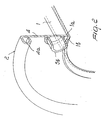
- FIG. 3 A first variation is shown in Figures 3 and 4 , and in such variation the wall elements 6 and 7 arranged at the ends of the tubular body 8 have mirror-symmetrically identical shapes, which are now described with reference to the element 6.
- Such element comprises a flat flange 9 and a complementary flat flange 10 which adheres thereto and is joined by seaming to the flange 9 at an outer edge 10a, and is provided with pins 11a,11b which are formed monolithically and which might be absent in the element 7.
- the element 6 is associated with the end of the body 8 so as to rest against an abutment 8a and be clamped against it by a fold 8b.
- a complementary flange 12 (see Figure 5 ) has a camber which, from an inner edge 12a in contact with a fold 13a of the wall of a tubular body 13, extends along the entire extension of the complementary flange, with pins 14 which are formed monolithically, so as to be spaced from a corresponding flange 15.
- Complementary flanges 16 and 17 of Figures 6 and 7 also have cambers which, by extending from inner edges 16a, 17a, cover their entire extension, and there are also studs 16b, 17b which are deep so as to come into contact with contiguous flanges, respectively 18 and 19; the complementary flange 16 has pins 16c which are formed at the studs, while the complementary flange 17 has pins 17c which are formed in gaps between the studs.
- a. complementary flange 20 (see Figure 8 ) has a camber 20a only at the inner edge, while the rest adheres to a corresponding flange 21; there are also pins 20b which are formed monolithically.
Landscapes
- Storage Of Web-Like Or Filamentary Materials (AREA)
- Windings For Motors And Generators (AREA)
Description
- The present invention relates to a wire winding spool.
- It is known that spools for winding wire which comprise a tubular body for supporting the coil of wire, provided at its ends with wall elements for containing the coil, are widely used in the industrial field.
- Known spools have a certain constructive complexity, which derives in particular from assemblies obtained by welding.
US 1,920,420 discloses a spool according to the preamble ofclaim 1. - Therefore the aim of the present invention is to provide a spool which has maximum simplicity.
- This aim is achieved by a wire winding spool, according to
claim 1. - Further characteristics and advantages of the present invention will become better apparent from the description of some preferred but not exclusive embodiments thereof, illustrated by way of non-limiting example in the accompanying drawings, wherein:
-
Figure 1 is a perspective view of a spool ; -
Figure 2 is a view of a detail ofFigure 1 ; -
Figure 3 is a perspective view of a first variation of the spool -
Figure 4 is a view of a detail ofFigure 3 ; -
Figures 5 to 8 are views of details of the spool shown inFigure 4 related to further variation according to the invention. - With reference to
Figures 1 and2 , thereference numeral 1 designates a tubular body for supporting a coil of wire, which is provided at the ends with twowall elements - Therefore, only the
element 2 is described; it is formed by aflat flange 4 with a stiffening fold 4a at the outer edge and weldeddriving pins element 3. - The
flange 4 is associated with the end of thetubular body 1 so as to rest against an abutment 1a provided on the outer surface of the wall of the body, clamped against it by a fold 1b of the end portion of the wall, which is obtained very easily by plastic deformation of the material. - It should be noted that the fold 1b, besides performing the function indicated above, acts as an effective guide for the penetration of the spindle designed to support the spool during operation.
- A first variation is shown in
Figures 3 and4 , and in such variation thewall elements tubular body 8 have mirror-symmetrically identical shapes, which are now described with reference to theelement 6. - Such element comprises a
flat flange 9 and a complementaryflat flange 10 which adheres thereto and is joined by seaming to theflange 9 at anouter edge 10a, and is provided withpins element 7. - In this case also, the
element 6 is associated with the end of thebody 8 so as to rest against an abutment 8a and be clamped against it by afold 8b. - The complementary flanges provided so as to form, by being joined by seaming at the corresponding outer edge to corresponding flat flanges, the wall elements of the variations of
Figures 5 to 8 , all have a camber at the inner edge, so as to come into contact with the fold of the end portion of the wall of the tubular body which, in all of such variations, clamps the wall elements against corresponding abutments. - More particularly, a complementary flange 12 (see
Figure 5 ) has a camber which, from aninner edge 12a in contact with a fold 13a of the wall of atubular body 13, extends along the entire extension of the complementary flange, withpins 14 which are formed monolithically, so as to be spaced from acorresponding flange 15. -
Complementary flanges Figures 6 and7 also have cambers which, by extending frominner edges 16a, 17a, cover their entire extension, and there are alsostuds 16b, 17b which are deep so as to come into contact with contiguous flanges, respectively 18 and 19; thecomplementary flange 16 haspins 16c which are formed at the studs, while thecomplementary flange 17 haspins 17c which are formed in gaps between the studs. - Finally, a. complementary flange 20 (see
Figure 8 ) has acamber 20a only at the inner edge, while the rest adheres to acorresponding flange 21; there are also pins 20b which are formed monolithically. - The described invention is susceptible of numerous other modifications and variations, which are within the scope of the appended claims;
- Where technical features mentioned in any claim are followed by reference signs, those reference signs have been included for the sole purpose of increasing the intelligibility of the claims and accordingly such reference signs do not have any limiting effect on the interpretation of each element identified by way of example by such reference signs.
Claims (7)
- A wire winding spool, comprising a tubular body (13) for supporting a coil of wire provided, at its ends, with wall elements for containing said coil, each wall element being associated with the corresponding end of the tubular body (13) so as to rest against an abutment provided on an outer surface of a wall of said body ( 13), clamped against it by a fold (13a), of the end portion of said wall, each wall element comprising a flat flange (15, 18, 19, 21) and a complementary flange (12, 16, 17, 20) which is joined by seaming to the outer surface of said flat flange (15, 18, 19, 21) at the outer edge, characterized in that said fold (13a) acts as an effective guide for the penetration of a spindle designed to support the spool during operation, said complementary flange (12, 16, 17, 20) having at least at the inner edge thereof a camber (12a, 16a, 17a, 20a), formed so as to come into contact with the fold (13a) of the end portion of the wall of the tubular body (13), at least one of said wall elements being provided, at the surface directed outwardly, with at least one pin (14, 16c, 17c, 20b) for engaging means for turning said spool.
- The spool according to claim 1, characterized in that the complementary flange (12, 16, 17) has a camber (12a, 16a, 17a) which extends along the entire extension thereof.
- The spool according to claim 1, characterized in that the complementary flange (16) has a camber (16a) which extends along the entire extension thereof and has deep studs (16b), pins (16c) being provided which are formed monolithically at the bottom of the studs (16b).
- The spool according to claim 1, characterized in that the complementary flange (17) has a camber (17a) which extends along the entire extension thereof and has deep studs (17b), pins (17c) being provided which are formed monolithically at gaps between he studs (17b).
- The spool according to claim 1, characterized in that the complementary flange (20) has a camber (20a) only at the inner edge.
- The spool according to one or more of the preceding claims, characterized in that at least one wall element provides for the presence of at least one pin which is rigidly coupled to said element.
- The spool according to one or more of the preceding claims, characterized in that at least one wall element has at least one pin (14, 16c, 17c, 20b) obtained monolithically from said element.
Applications Claiming Priority (2)
| Application Number | Priority Date | Filing Date | Title |
|---|---|---|---|
| IT000017A ITMN20070017A1 (en) | 2007-04-20 | 2007-04-20 | METAL THREAD WINDING COIL |
| PCT/EP2008/054538 WO2008128925A1 (en) | 2007-04-20 | 2008-04-15 | Wire winding spool |
Publications (2)
| Publication Number | Publication Date |
|---|---|
| EP2139802A1 EP2139802A1 (en) | 2010-01-06 |
| EP2139802B1 true EP2139802B1 (en) | 2013-02-20 |
Family
ID=39587044
Family Applications (1)
| Application Number | Title | Priority Date | Filing Date |
|---|---|---|---|
| EP08736230A Not-in-force EP2139802B1 (en) | 2007-04-20 | 2008-04-15 | Wire winding spool |
Country Status (4)
| Country | Link |
|---|---|
| US (1) | US8047463B2 (en) |
| EP (1) | EP2139802B1 (en) |
| IT (1) | ITMN20070017A1 (en) |
| WO (1) | WO2008128925A1 (en) |
Families Citing this family (6)
| Publication number | Priority date | Publication date | Assignee | Title |
|---|---|---|---|---|
| ITMN20080002U1 (en) * | 2008-02-14 | 2009-08-15 | Gmp Slovakia S R O | METAL THREAD WINDING COIL |
| MY152516A (en) * | 2008-11-27 | 2014-10-15 | Bekaert Sa Nv | Improved sawing wire spool |
| JP6202033B2 (en) * | 2014-05-15 | 2017-09-27 | 株式会社村田製作所 | Taping electronic component continuous reel and manufacturing method thereof |
| US10577230B1 (en) | 2018-10-22 | 2020-03-03 | Gary Shelton | Winch device |
| US10994845B2 (en) | 2019-06-06 | 2021-05-04 | B/E Aerospace, Inc. | Waste system pressure management system |
| CA3219131A1 (en) * | 2021-05-26 | 2022-12-01 | Caden PERRY | Biomass feedstock recovery equipment and processes |
Family Cites Families (17)
| Publication number | Priority date | Publication date | Assignee | Title |
|---|---|---|---|---|
| US298378A (en) * | 1884-05-13 | Hermetic jar | ||
| US1528985A (en) * | 1921-10-08 | 1925-03-10 | American Can Co | Reenforced-metal spool |
| US1598912A (en) * | 1925-11-02 | 1926-09-07 | Penrose R Hoopes | Spool |
| US1672167A (en) * | 1926-03-01 | 1928-06-05 | Mossberg Pressed Steel Corp | Spool |
| US1699700A (en) * | 1927-01-20 | 1929-01-22 | Clark Mfg Co J L | Metallic spool |
| US1920420A (en) * | 1929-11-20 | 1933-08-01 | Clark Mfg Co J L | Metallic spool or reel |
| US1920422A (en) * | 1930-06-23 | 1933-08-01 | Clark Mfg Co J L | Metallic spool |
| US1892356A (en) * | 1930-12-05 | 1932-12-27 | Clark Mfg Co J L | Spool |
| US2514932A (en) * | 1946-10-30 | 1950-07-11 | Western Electric Co | Reel |
| US2521922A (en) * | 1947-11-08 | 1950-09-12 | Western Electric Co | Welded metal reel |
| US2662701A (en) * | 1950-08-17 | 1953-12-15 | Reynolds Metals Co | Reel apparatus for forming coils of cable |
| FR2318093A1 (en) * | 1975-07-18 | 1977-02-11 | Seifert & Co Nachf Ind | WINDING DRUM FOR CABLES, METAL WIRES, ETC ... |
| AU2740984A (en) | 1983-04-29 | 1984-11-01 | National Can Company Pty Ltd | Flanged spool member |
| US5106031A (en) * | 1991-03-26 | 1992-04-21 | Tokusen Kogyo Company Limited | Reel for winding metallic wire |
| US6289570B1 (en) * | 1999-05-25 | 2001-09-18 | J. L. Clark, Inc. | Die and method for assembling metal spool having high torque transmitting capacity between spool components |
| JP2003089478A (en) * | 2001-09-19 | 2003-03-25 | Kanai Hiroaki | Reel for extra fine metal wire and its manufacturing method |
| US7222818B2 (en) * | 2004-10-22 | 2007-05-29 | Sonoco Development, Inc. | Shipping spool |
-
2007
- 2007-04-20 IT IT000017A patent/ITMN20070017A1/en unknown
-
2008
- 2008-04-15 WO PCT/EP2008/054538 patent/WO2008128925A1/en not_active Ceased
- 2008-04-15 US US12/595,578 patent/US8047463B2/en not_active Expired - Fee Related
- 2008-04-15 EP EP08736230A patent/EP2139802B1/en not_active Not-in-force
Also Published As
| Publication number | Publication date |
|---|---|
| WO2008128925A1 (en) | 2008-10-30 |
| US20100140387A1 (en) | 2010-06-10 |
| US8047463B2 (en) | 2011-11-01 |
| EP2139802A1 (en) | 2010-01-06 |
| WO2008128925A8 (en) | 2009-05-22 |
| ITMN20070017A1 (en) | 2008-10-21 |
Similar Documents
| Publication | Publication Date | Title |
|---|---|---|
| EP2139802B1 (en) | Wire winding spool | |
| CN104918722B (en) | For the method manufacturing endless belt | |
| US10184239B2 (en) | Covering consisting of a plurality of gratings inserted one into another | |
| CA2134184A1 (en) | Ring binder mechanism | |
| US20170136971A1 (en) | Bumper reinforcement | |
| KR20180019094A (en) | Paper reel | |
| EP2687428B1 (en) | Vehicular wheel house portion structure | |
| WO2015186700A1 (en) | Torsion beam suspension | |
| JP2005305547A (en) | Thin sheet element and method for manufacturing thin sheet element | |
| CN105378362B (en) | Hose clamp | |
| WO2012115186A1 (en) | Torsion beam type suspension | |
| EP2240394B1 (en) | Spool for winding metallic wire | |
| EP3124297B1 (en) | Torsion beam suspension | |
| KR101316396B1 (en) | Container, lid, and seaming method for container | |
| JP5950393B2 (en) | Catheter holding mount | |
| CN105234577A (en) | Structural component and electrical equipment comprising same | |
| JPH07148577A (en) | Weld stud and manufacturing method thereof | |
| KR101948698B1 (en) | Container for welding wire | |
| JP2015229391A (en) | Door sash and method for manufacturing the same | |
| KR101030724B1 (en) | Split core insulating paper of stator and its insulation method | |
| US20060075920A1 (en) | Structural part for the body or undercarriage of a motor vehicle | |
| CN204171547U (en) | Structure member and comprise the electrical equipment of this structure member | |
| JP3847675B2 (en) | Corrugated tube | |
| KR101542948B1 (en) | Punching device for manufacturing which improve productivity | |
| JP3142391U (en) | Notebook cover |
Legal Events
| Date | Code | Title | Description |
|---|---|---|---|
| PUAI | Public reference made under article 153(3) epc to a published international application that has entered the european phase |
Free format text: ORIGINAL CODE: 0009012 |
|
| AK | Designated contracting states |
Kind code of ref document: A1 Designated state(s): AT BE BG CH CY CZ DE DK EE ES FI FR GB GR HR HU IE IS IT LI LT LU LV MC MT NL NO PL PT RO SE SI SK TR |
|
| 17P | Request for examination filed |
Effective date: 20091008 |
|
| DAX | Request for extension of the european patent (deleted) | ||
| 17Q | First examination report despatched |
Effective date: 20101008 |
|
| RAP1 | Party data changed (applicant data changed or rights of an application transferred) |
Owner name: VELAWORKS. S.R.O. |
|
| GRAP | Despatch of communication of intention to grant a patent |
Free format text: ORIGINAL CODE: EPIDOSNIGR1 |
|
| GRAS | Grant fee paid |
Free format text: ORIGINAL CODE: EPIDOSNIGR3 |
|
| GRAP | Despatch of communication of intention to grant a patent |
Free format text: ORIGINAL CODE: EPIDOSNIGR1 |
|
| GRAA | (expected) grant |
Free format text: ORIGINAL CODE: 0009210 |
|
| AK | Designated contracting states |
Kind code of ref document: B1 Designated state(s): AT BE BG CH CY CZ DE DK EE ES FI FR GB GR HR HU IE IS IT LI LT LU LV MC MT NL NO PL PT RO SE SI SK TR |
|
| REG | Reference to a national code |
Ref country code: GB Ref legal event code: FG4D |
|
| REG | Reference to a national code |
Ref country code: CH Ref legal event code: EP |
|
| REG | Reference to a national code |
Ref country code: AT Ref legal event code: REF Ref document number: 597454 Country of ref document: AT Kind code of ref document: T Effective date: 20130315 |
|
| REG | Reference to a national code |
Ref country code: IE Ref legal event code: FG4D |
|
| REG | Reference to a national code |
Ref country code: DE Ref legal event code: R096 Ref document number: 602008022286 Country of ref document: DE Effective date: 20130418 |
|
| REG | Reference to a national code |
Ref country code: AT Ref legal event code: MK05 Ref document number: 597454 Country of ref document: AT Kind code of ref document: T Effective date: 20130220 |
|
| REG | Reference to a national code |
Ref country code: NL Ref legal event code: VDEP Effective date: 20130220 |
|
| REG | Reference to a national code |
Ref country code: LT Ref legal event code: MG4D |
|
| PG25 | Lapsed in a contracting state [announced via postgrant information from national office to epo] |
Ref country code: ES Free format text: LAPSE BECAUSE OF FAILURE TO SUBMIT A TRANSLATION OF THE DESCRIPTION OR TO PAY THE FEE WITHIN THE PRESCRIBED TIME-LIMIT Effective date: 20130531 Ref country code: LT Free format text: LAPSE BECAUSE OF FAILURE TO SUBMIT A TRANSLATION OF THE DESCRIPTION OR TO PAY THE FEE WITHIN THE PRESCRIBED TIME-LIMIT Effective date: 20130220 Ref country code: IS Free format text: LAPSE BECAUSE OF FAILURE TO SUBMIT A TRANSLATION OF THE DESCRIPTION OR TO PAY THE FEE WITHIN THE PRESCRIBED TIME-LIMIT Effective date: 20130620 Ref country code: NO Free format text: LAPSE BECAUSE OF FAILURE TO SUBMIT A TRANSLATION OF THE DESCRIPTION OR TO PAY THE FEE WITHIN THE PRESCRIBED TIME-LIMIT Effective date: 20130520 Ref country code: AT Free format text: LAPSE BECAUSE OF FAILURE TO SUBMIT A TRANSLATION OF THE DESCRIPTION OR TO PAY THE FEE WITHIN THE PRESCRIBED TIME-LIMIT Effective date: 20130220 Ref country code: SE Free format text: LAPSE BECAUSE OF FAILURE TO SUBMIT A TRANSLATION OF THE DESCRIPTION OR TO PAY THE FEE WITHIN THE PRESCRIBED TIME-LIMIT Effective date: 20130220 Ref country code: BG Free format text: LAPSE BECAUSE OF FAILURE TO SUBMIT A TRANSLATION OF THE DESCRIPTION OR TO PAY THE FEE WITHIN THE PRESCRIBED TIME-LIMIT Effective date: 20130520 |
|
| REG | Reference to a national code |
Ref country code: SK Ref legal event code: T3 Ref document number: E 14085 Country of ref document: SK |
|
| PG25 | Lapsed in a contracting state [announced via postgrant information from national office to epo] |
Ref country code: GR Free format text: LAPSE BECAUSE OF FAILURE TO SUBMIT A TRANSLATION OF THE DESCRIPTION OR TO PAY THE FEE WITHIN THE PRESCRIBED TIME-LIMIT Effective date: 20130521 Ref country code: PL Free format text: LAPSE BECAUSE OF FAILURE TO SUBMIT A TRANSLATION OF THE DESCRIPTION OR TO PAY THE FEE WITHIN THE PRESCRIBED TIME-LIMIT Effective date: 20130220 Ref country code: SI Free format text: LAPSE BECAUSE OF FAILURE TO SUBMIT A TRANSLATION OF THE DESCRIPTION OR TO PAY THE FEE WITHIN THE PRESCRIBED TIME-LIMIT Effective date: 20130220 Ref country code: PT Free format text: LAPSE BECAUSE OF FAILURE TO SUBMIT A TRANSLATION OF THE DESCRIPTION OR TO PAY THE FEE WITHIN THE PRESCRIBED TIME-LIMIT Effective date: 20130620 Ref country code: FI Free format text: LAPSE BECAUSE OF FAILURE TO SUBMIT A TRANSLATION OF THE DESCRIPTION OR TO PAY THE FEE WITHIN THE PRESCRIBED TIME-LIMIT Effective date: 20130220 Ref country code: BE Free format text: LAPSE BECAUSE OF FAILURE TO SUBMIT A TRANSLATION OF THE DESCRIPTION OR TO PAY THE FEE WITHIN THE PRESCRIBED TIME-LIMIT Effective date: 20130220 Ref country code: LV Free format text: LAPSE BECAUSE OF FAILURE TO SUBMIT A TRANSLATION OF THE DESCRIPTION OR TO PAY THE FEE WITHIN THE PRESCRIBED TIME-LIMIT Effective date: 20130220 |
|
| PG25 | Lapsed in a contracting state [announced via postgrant information from national office to epo] |
Ref country code: HR Free format text: LAPSE BECAUSE OF FAILURE TO SUBMIT A TRANSLATION OF THE DESCRIPTION OR TO PAY THE FEE WITHIN THE PRESCRIBED TIME-LIMIT Effective date: 20130220 |
|
| PG25 | Lapsed in a contracting state [announced via postgrant information from national office to epo] |
Ref country code: DK Free format text: LAPSE BECAUSE OF FAILURE TO SUBMIT A TRANSLATION OF THE DESCRIPTION OR TO PAY THE FEE WITHIN THE PRESCRIBED TIME-LIMIT Effective date: 20130220 Ref country code: RO Free format text: LAPSE BECAUSE OF FAILURE TO SUBMIT A TRANSLATION OF THE DESCRIPTION OR TO PAY THE FEE WITHIN THE PRESCRIBED TIME-LIMIT Effective date: 20130220 Ref country code: EE Free format text: LAPSE BECAUSE OF FAILURE TO SUBMIT A TRANSLATION OF THE DESCRIPTION OR TO PAY THE FEE WITHIN THE PRESCRIBED TIME-LIMIT Effective date: 20130220 Ref country code: CZ Free format text: LAPSE BECAUSE OF FAILURE TO SUBMIT A TRANSLATION OF THE DESCRIPTION OR TO PAY THE FEE WITHIN THE PRESCRIBED TIME-LIMIT Effective date: 20130220 Ref country code: NL Free format text: LAPSE BECAUSE OF FAILURE TO SUBMIT A TRANSLATION OF THE DESCRIPTION OR TO PAY THE FEE WITHIN THE PRESCRIBED TIME-LIMIT Effective date: 20130220 |
|
| PG25 | Lapsed in a contracting state [announced via postgrant information from national office to epo] |
Ref country code: CY Free format text: LAPSE BECAUSE OF FAILURE TO SUBMIT A TRANSLATION OF THE DESCRIPTION OR TO PAY THE FEE WITHIN THE PRESCRIBED TIME-LIMIT Effective date: 20130220 Ref country code: MC Free format text: LAPSE BECAUSE OF FAILURE TO SUBMIT A TRANSLATION OF THE DESCRIPTION OR TO PAY THE FEE WITHIN THE PRESCRIBED TIME-LIMIT Effective date: 20130220 |
|
| REG | Reference to a national code |
Ref country code: CH Ref legal event code: PL |
|
| PLBE | No opposition filed within time limit |
Free format text: ORIGINAL CODE: 0009261 |
|
| STAA | Information on the status of an ep patent application or granted ep patent |
Free format text: STATUS: NO OPPOSITION FILED WITHIN TIME LIMIT |
|
| REG | Reference to a national code |
Ref country code: SK Ref legal event code: MM4A Ref document number: E 14085 Country of ref document: SK Effective date: 20130415 |
|
| 26N | No opposition filed |
Effective date: 20131121 |
|
| GBPC | Gb: european patent ceased through non-payment of renewal fee |
Effective date: 20130520 |
|
| REG | Reference to a national code |
Ref country code: IE Ref legal event code: MM4A |
|
| PG25 | Lapsed in a contracting state [announced via postgrant information from national office to epo] |
Ref country code: SK Free format text: LAPSE BECAUSE OF NON-PAYMENT OF DUE FEES Effective date: 20130415 Ref country code: CH Free format text: LAPSE BECAUSE OF NON-PAYMENT OF DUE FEES Effective date: 20130430 Ref country code: LI Free format text: LAPSE BECAUSE OF NON-PAYMENT OF DUE FEES Effective date: 20130430 |
|
| REG | Reference to a national code |
Ref country code: DE Ref legal event code: R097 Ref document number: 602008022286 Country of ref document: DE Effective date: 20131121 |
|
| PG25 | Lapsed in a contracting state [announced via postgrant information from national office to epo] |
Ref country code: GB Free format text: LAPSE BECAUSE OF NON-PAYMENT OF DUE FEES Effective date: 20130520 Ref country code: IE Free format text: LAPSE BECAUSE OF NON-PAYMENT OF DUE FEES Effective date: 20130415 |
|
| PGFP | Annual fee paid to national office [announced via postgrant information from national office to epo] |
Ref country code: LU Payment date: 20140508 Year of fee payment: 7 |
|
| PGFP | Annual fee paid to national office [announced via postgrant information from national office to epo] |
Ref country code: FR Payment date: 20140429 Year of fee payment: 7 Ref country code: DE Payment date: 20140425 Year of fee payment: 7 Ref country code: IT Payment date: 20140428 Year of fee payment: 7 |
|
| PG25 | Lapsed in a contracting state [announced via postgrant information from national office to epo] |
Ref country code: MT Free format text: LAPSE BECAUSE OF FAILURE TO SUBMIT A TRANSLATION OF THE DESCRIPTION OR TO PAY THE FEE WITHIN THE PRESCRIBED TIME-LIMIT Effective date: 20130220 |
|
| PG25 | Lapsed in a contracting state [announced via postgrant information from national office to epo] |
Ref country code: TR Free format text: LAPSE BECAUSE OF FAILURE TO SUBMIT A TRANSLATION OF THE DESCRIPTION OR TO PAY THE FEE WITHIN THE PRESCRIBED TIME-LIMIT Effective date: 20130220 |
|
| PG25 | Lapsed in a contracting state [announced via postgrant information from national office to epo] |
Ref country code: HU Free format text: LAPSE BECAUSE OF FAILURE TO SUBMIT A TRANSLATION OF THE DESCRIPTION OR TO PAY THE FEE WITHIN THE PRESCRIBED TIME-LIMIT; INVALID AB INITIO Effective date: 20080415 |
|
| REG | Reference to a national code |
Ref country code: DE Ref legal event code: R119 Ref document number: 602008022286 Country of ref document: DE |
|
| PG25 | Lapsed in a contracting state [announced via postgrant information from national office to epo] |
Ref country code: LU Free format text: LAPSE BECAUSE OF NON-PAYMENT OF DUE FEES Effective date: 20150415 |
|
| PG25 | Lapsed in a contracting state [announced via postgrant information from national office to epo] |
Ref country code: DE Free format text: LAPSE BECAUSE OF NON-PAYMENT OF DUE FEES Effective date: 20151103 Ref country code: IT Free format text: LAPSE BECAUSE OF NON-PAYMENT OF DUE FEES Effective date: 20150415 |
|
| REG | Reference to a national code |
Ref country code: FR Ref legal event code: ST Effective date: 20151231 |
|
| PG25 | Lapsed in a contracting state [announced via postgrant information from national office to epo] |
Ref country code: FR Free format text: LAPSE BECAUSE OF NON-PAYMENT OF DUE FEES Effective date: 20150430 |