EP2139666B1 - Transfer device and linear-type apparatus for the manufacture of containers - Google Patents
Transfer device and linear-type apparatus for the manufacture of containers Download PDFInfo
- Publication number
- EP2139666B1 EP2139666B1 EP08736448A EP08736448A EP2139666B1 EP 2139666 B1 EP2139666 B1 EP 2139666B1 EP 08736448 A EP08736448 A EP 08736448A EP 08736448 A EP08736448 A EP 08736448A EP 2139666 B1 EP2139666 B1 EP 2139666B1
- Authority
- EP
- European Patent Office
- Prior art keywords
- transfer device
- gripper
- preform
- clamp
- preforms
- Prior art date
- Legal status (The legal status is an assumption and is not a legal conclusion. Google has not performed a legal analysis and makes no representation as to the accuracy of the status listed.)
- Not-in-force
Links
Images


Classifications
-
- B—PERFORMING OPERATIONS; TRANSPORTING
- B29—WORKING OF PLASTICS; WORKING OF SUBSTANCES IN A PLASTIC STATE IN GENERAL
- B29C—SHAPING OR JOINING OF PLASTICS; SHAPING OF MATERIAL IN A PLASTIC STATE, NOT OTHERWISE PROVIDED FOR; AFTER-TREATMENT OF THE SHAPED PRODUCTS, e.g. REPAIRING
- B29C49/00—Blow-moulding, i.e. blowing a preform or parison to a desired shape within a mould; Apparatus therefor
- B29C49/42—Component parts, details or accessories; Auxiliary operations
- B29C49/4205—Handling means, e.g. transfer, loading or discharging means
- B29C49/42113—Means for manipulating the objects' position or orientation
- B29C49/42121—Changing the center-center distance
- B29C49/42122—Adapting to blow-mould cavity center-center distance
-
- B—PERFORMING OPERATIONS; TRANSPORTING
- B29—WORKING OF PLASTICS; WORKING OF SUBSTANCES IN A PLASTIC STATE IN GENERAL
- B29C—SHAPING OR JOINING OF PLASTICS; SHAPING OF MATERIAL IN A PLASTIC STATE, NOT OTHERWISE PROVIDED FOR; AFTER-TREATMENT OF THE SHAPED PRODUCTS, e.g. REPAIRING
- B29C49/00—Blow-moulding, i.e. blowing a preform or parison to a desired shape within a mould; Apparatus therefor
- B29C49/42—Component parts, details or accessories; Auxiliary operations
- B29C49/4205—Handling means, e.g. transfer, loading or discharging means
- B29C49/42069—Means explicitly adapted for transporting blown article
-
- B—PERFORMING OPERATIONS; TRANSPORTING
- B65—CONVEYING; PACKING; STORING; HANDLING THIN OR FILAMENTARY MATERIAL
- B65G—TRANSPORT OR STORAGE DEVICES, e.g. CONVEYORS FOR LOADING OR TIPPING, SHOP CONVEYOR SYSTEMS OR PNEUMATIC TUBE CONVEYORS
- B65G47/00—Article or material-handling devices associated with conveyors; Methods employing such devices
- B65G47/74—Feeding, transfer, or discharging devices of particular kinds or types
- B65G47/90—Devices for picking-up and depositing articles or materials
- B65G47/901—Devices for picking-up and depositing articles or materials provided with drive systems with rectilinear movements only
-
- B—PERFORMING OPERATIONS; TRANSPORTING
- B29—WORKING OF PLASTICS; WORKING OF SUBSTANCES IN A PLASTIC STATE IN GENERAL
- B29C—SHAPING OR JOINING OF PLASTICS; SHAPING OF MATERIAL IN A PLASTIC STATE, NOT OTHERWISE PROVIDED FOR; AFTER-TREATMENT OF THE SHAPED PRODUCTS, e.g. REPAIRING
- B29C2949/00—Indexing scheme relating to blow-moulding
- B29C2949/07—Preforms or parisons characterised by their configuration
- B29C2949/0715—Preforms or parisons characterised by their configuration the preform having one end closed
-
- B—PERFORMING OPERATIONS; TRANSPORTING
- B29—WORKING OF PLASTICS; WORKING OF SUBSTANCES IN A PLASTIC STATE IN GENERAL
- B29C—SHAPING OR JOINING OF PLASTICS; SHAPING OF MATERIAL IN A PLASTIC STATE, NOT OTHERWISE PROVIDED FOR; AFTER-TREATMENT OF THE SHAPED PRODUCTS, e.g. REPAIRING
- B29C2949/00—Indexing scheme relating to blow-moulding
- B29C2949/20—Preforms or parisons whereby a specific part is made of only one component, e.g. only one layer
- B29C2949/22—Preforms or parisons whereby a specific part is made of only one component, e.g. only one layer at neck portion
-
- B—PERFORMING OPERATIONS; TRANSPORTING
- B29—WORKING OF PLASTICS; WORKING OF SUBSTANCES IN A PLASTIC STATE IN GENERAL
- B29C—SHAPING OR JOINING OF PLASTICS; SHAPING OF MATERIAL IN A PLASTIC STATE, NOT OTHERWISE PROVIDED FOR; AFTER-TREATMENT OF THE SHAPED PRODUCTS, e.g. REPAIRING
- B29C2949/00—Indexing scheme relating to blow-moulding
- B29C2949/20—Preforms or parisons whereby a specific part is made of only one component, e.g. only one layer
- B29C2949/24—Preforms or parisons whereby a specific part is made of only one component, e.g. only one layer at flange portion
-
- B—PERFORMING OPERATIONS; TRANSPORTING
- B29—WORKING OF PLASTICS; WORKING OF SUBSTANCES IN A PLASTIC STATE IN GENERAL
- B29C—SHAPING OR JOINING OF PLASTICS; SHAPING OF MATERIAL IN A PLASTIC STATE, NOT OTHERWISE PROVIDED FOR; AFTER-TREATMENT OF THE SHAPED PRODUCTS, e.g. REPAIRING
- B29C2949/00—Indexing scheme relating to blow-moulding
- B29C2949/20—Preforms or parisons whereby a specific part is made of only one component, e.g. only one layer
- B29C2949/26—Preforms or parisons whereby a specific part is made of only one component, e.g. only one layer at body portion
-
- B—PERFORMING OPERATIONS; TRANSPORTING
- B29—WORKING OF PLASTICS; WORKING OF SUBSTANCES IN A PLASTIC STATE IN GENERAL
- B29C—SHAPING OR JOINING OF PLASTICS; SHAPING OF MATERIAL IN A PLASTIC STATE, NOT OTHERWISE PROVIDED FOR; AFTER-TREATMENT OF THE SHAPED PRODUCTS, e.g. REPAIRING
- B29C2949/00—Indexing scheme relating to blow-moulding
- B29C2949/20—Preforms or parisons whereby a specific part is made of only one component, e.g. only one layer
- B29C2949/28—Preforms or parisons whereby a specific part is made of only one component, e.g. only one layer at bottom portion
-
- B—PERFORMING OPERATIONS; TRANSPORTING
- B29—WORKING OF PLASTICS; WORKING OF SUBSTANCES IN A PLASTIC STATE IN GENERAL
- B29C—SHAPING OR JOINING OF PLASTICS; SHAPING OF MATERIAL IN A PLASTIC STATE, NOT OTHERWISE PROVIDED FOR; AFTER-TREATMENT OF THE SHAPED PRODUCTS, e.g. REPAIRING
- B29C2949/00—Indexing scheme relating to blow-moulding
- B29C2949/30—Preforms or parisons made of several components
- B29C2949/3024—Preforms or parisons made of several components characterised by the number of components or by the manufacturing technique
-
- B—PERFORMING OPERATIONS; TRANSPORTING
- B29—WORKING OF PLASTICS; WORKING OF SUBSTANCES IN A PLASTIC STATE IN GENERAL
- B29C—SHAPING OR JOINING OF PLASTICS; SHAPING OF MATERIAL IN A PLASTIC STATE, NOT OTHERWISE PROVIDED FOR; AFTER-TREATMENT OF THE SHAPED PRODUCTS, e.g. REPAIRING
- B29C2949/00—Indexing scheme relating to blow-moulding
- B29C2949/30—Preforms or parisons made of several components
- B29C2949/3032—Preforms or parisons made of several components having components being injected
-
- B—PERFORMING OPERATIONS; TRANSPORTING
- B29—WORKING OF PLASTICS; WORKING OF SUBSTANCES IN A PLASTIC STATE IN GENERAL
- B29C—SHAPING OR JOINING OF PLASTICS; SHAPING OF MATERIAL IN A PLASTIC STATE, NOT OTHERWISE PROVIDED FOR; AFTER-TREATMENT OF THE SHAPED PRODUCTS, e.g. REPAIRING
- B29C49/00—Blow-moulding, i.e. blowing a preform or parison to a desired shape within a mould; Apparatus therefor
- B29C49/02—Combined blow-moulding and manufacture of the preform or the parison
- B29C49/06—Injection blow-moulding
-
- B—PERFORMING OPERATIONS; TRANSPORTING
- B29—WORKING OF PLASTICS; WORKING OF SUBSTANCES IN A PLASTIC STATE IN GENERAL
- B29C—SHAPING OR JOINING OF PLASTICS; SHAPING OF MATERIAL IN A PLASTIC STATE, NOT OTHERWISE PROVIDED FOR; AFTER-TREATMENT OF THE SHAPED PRODUCTS, e.g. REPAIRING
- B29C49/00—Blow-moulding, i.e. blowing a preform or parison to a desired shape within a mould; Apparatus therefor
- B29C49/42—Component parts, details or accessories; Auxiliary operations
- B29C49/4205—Handling means, e.g. transfer, loading or discharging means
- B29C49/42073—Grippers
- B29C49/42075—Grippers with pivoting clamps
-
- B—PERFORMING OPERATIONS; TRANSPORTING
- B29—WORKING OF PLASTICS; WORKING OF SUBSTANCES IN A PLASTIC STATE IN GENERAL
- B29C—SHAPING OR JOINING OF PLASTICS; SHAPING OF MATERIAL IN A PLASTIC STATE, NOT OTHERWISE PROVIDED FOR; AFTER-TREATMENT OF THE SHAPED PRODUCTS, e.g. REPAIRING
- B29C49/00—Blow-moulding, i.e. blowing a preform or parison to a desired shape within a mould; Apparatus therefor
- B29C49/42—Component parts, details or accessories; Auxiliary operations
- B29C49/4205—Handling means, e.g. transfer, loading or discharging means
- B29C49/42073—Grippers
- B29C49/42087—Grippers holding outside the neck
-
- B—PERFORMING OPERATIONS; TRANSPORTING
- B65—CONVEYING; PACKING; STORING; HANDLING THIN OR FILAMENTARY MATERIAL
- B65G—TRANSPORT OR STORAGE DEVICES, e.g. CONVEYORS FOR LOADING OR TIPPING, SHOP CONVEYOR SYSTEMS OR PNEUMATIC TUBE CONVEYORS
- B65G2201/00—Indexing codes relating to handling devices, e.g. conveyors, characterised by the type of product or load being conveyed or handled
- B65G2201/02—Articles
- B65G2201/0235—Containers
- B65G2201/0244—Bottles
Definitions
- the invention relates to a transfer device, including preforms or containers, and a linear type of installation for the manufacture of containers comprising such a device.
- containers such as a bottle or a bottle
- preforms made of plastic material for example PET (polyethylene terephthalate).
- the preforms are generally, at first, heated on the run in a conditioning unit or heat treatment comprising at least one oven for heating the preforms to a predetermined temperature close to their glass transition temperature and are in a second step, transferred directly to a molding unit, also called blowing unit, to be shaped by blow molding or stretch-blow molding.
- a conditioning unit or heat treatment comprising at least one oven for heating the preforms to a predetermined temperature close to their glass transition temperature and are in a second step, transferred directly to a molding unit, also called blowing unit, to be shaped by blow molding or stretch-blow molding.
- Such installations comprise at least one transfer device for transporting between the various units the preforms and / or the containers, generally via their necks provided with a radial flange.
- the molding unit of the installation is a rotary machine comprising a carousel which carries a plurality of molds distributed around its circumference, each mold, sometimes called a "wallet" mold, comprising two half-molds mounted in rotation relative to each other along an axis parallel to the axis of the container, and where the containers are successively molded to the unit.
- the molding unit of the installation is said to be of the "linear" type because, by comparison, the machine comprises a mold which comprises two half-molds that are displaceable in translation relative to each other, perpendicular to the joint plane of the mold.
- Production rates are generally higher in the first family facilities (greater than 1500 containers / hour / mold) than in the second family facilities.
- the transfer device has the particular function of carrying a group of preforms (or blanks) from the furnace outlet of the thermal conditioning unit, where they are loaded, to the molding unit where they are discharged for blow molding or stretch blow molding in as many containers, in this case in groups of four containers.
- This document describes more particularly connecting means able to vary the spacing between the modules constituting the transfer device, more precisely to vary the spacing between the modules of a primary pitch P1 corresponding to the spacing between two successive preforms at the outlet of the oven, at a secondary pitch P2, greater than the primary pitch P1, which corresponds to the spacing required for unloading between each module carrying a preform and which is determined by the spacing in the mold between two successive imprints of containers.
- Each module (or carriage) of the transfer device comprises gripping means formed by a clamp comprising two articulated jaws, around an axis B, between an open position and a closed position towards which the jaws of the clamp are resiliently biased through an elastic member.
- the gripper To load a preform, the gripper must successively open (open position) so that the jaws are positioned around the neck of the preform and then close around the neck (closed position) above the collar of the preform.
- the movement of the jaws of the clamp between the open and closed positions is not controlled selectively but obtained directly by cooperation with the neck of the preform.
- each jaw of the clamp advantageously has a determined "V" profile which consists of a first front surface and a second rear surface each forming a ramp intended to cooperate with the neck of the preform respectively during loading (gripping) and during unloading (release).
- the clamp is moved transversely forwardly towards the preform and synchronously with respect to the speed of movement of the preforms which, coming from the furnace, circulate according to the longitudinal direction of displacement.
- Each clamp will come into contact with the part of the neck of the preform located above the collar and the jaws will then move away and then close immediately around the neck under the biasing force of the elastic member, the opening of the clamp being facilitated by the cooperation of shapes between the first front surface of the "V" profile and the cylindrical neck of the preform.
- the opening of the jaws of the clamp is thus obtained by engagement of the clamp on the neck of the preform with sufficient force to overcome the force exerted on the jaws by the elastic return member, that is to say say obtained by engagement or introduction "in force".
- a heat treatment of the body of the preform by "preferential heating” consists in selectively and differently heating certain portions of the body of the preform so that the temperature in the entire body of the preform is not homogeneous along the axis of the preform. preform but has relatively warmer longitudinal portions which alternate with other relatively inferior longitudinal intermediate portions, the former being suitable for deform more easily than the latter during the subsequent deformation of the body of the preform during blowing or stretch-blow molding.
- container of complex shape is generally meant a final container which is not approximately cylindrical of revolution but which has for example a polygonal horizontal section (triangular, quadrangular, pentagonal, etc.) or a container with a flattened body, such as the vials intended to contain cleaning or hygiene products and whose necks are provided with means for spraying or spraying the product, see a plug.
- a polygonal horizontal section triangular, quadrangular, pentagonal, etc.
- container with a flattened body such as the vials intended to contain cleaning or hygiene products and whose necks are provided with means for spraying or spraying the product, see a plug.
- a transfer device of the type described in the document EN-A1-2.879.179 mentioned above is unsatisfactory, especially for the transport of heat-treated preforms according to a "preferential heating" process.
- the transfer device must make it possible to transport the preforms from the furnace to the mold while maintaining each preform in said determined reference position, when the installation is of the type comprising a thermal conditioning unit with a preferential heating furnace.
- a transfer device of the aforementioned type ( EN-A1-2.879.179 ) can still cause, when fitting the jaws of the clamp for gripping or releasing the containers, the appearance of more or less accentuated marks on the necks of the preforms or containers, which is particularly detrimental to the quality final container.
- this problem of marks and deterioration of the neck is further increased due to the fact that this type of treatment is in particular intended for the manufacture of containers of complex shape, such as vials, which generally have less resistant necks compared to the neck of a conventional bottle having a cylindrical shape of revolution.
- the force introduction of the jaws of the clamp around the neck sometimes causes the appearance of material chips which constitute an undesirable pollution likely to affect in particular the process of manufacture or deterioration of the container as it becomes irremediably unusable because too fragile or aesthetically unacceptable.
- the present invention aims to solve the aforementioned drawbacks, in particular the control of the angular position of the preform during the transfer and the deterioration of the neck of the preform or the container.
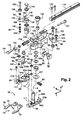
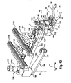
- FIG. 1 Diagrammatically shown in figure 1 , a linear type installation 10 for the manufacture of containers 12 from preforms 14.
- the preforms 14 are made of thermoplastic material, in particular PET (polyethylene terephthalate) intended to be heated and then blow-molded or stretch blow-molded in order to finally obtain containers 12, such as bottles or bottles. .
- PET polyethylene terephthalate
- the preforms 14 are generally manufactured according to an injection molding process, a molding step that can be integrated into the installation or carried out in a place other than that where the installation 10 is located.
- the preform 14 has the overall shape of a tube which here extends vertically along a vertical main axis A.
- the preform 14 comprises a body 16, here generally cylindrical, which is closed at its lower end by a bottom 18 and which, on the opposite side, is open at its upper end by an opening 20 delimited by the rim of a neck 22 .
- the inner cylindrical wall 26 of the body 16 of the preform 14 defines an internal volume corresponding, after blowing the preform, to the interior of the final container 12, which is intended to be subsequently filled by the opening 20.
- the neck 22 of the preform 14 already has the final shape of the neck of the final container 12, for example the neck 22 of a bottle, as illustrated in detail by the Figure 1B .
- the neck 22 is provided with means 24, represented here in the form of a helical thread, suitable for cooperate with complementary means of a plug 27 for closing the container 12.
- the neck 22 has at least one outer flange 28 which extends radially outwardly over the entire circumference of the lower part of the neck 22.
- the neck 22 comprises a bead 30 which, arranged vertically above the flange 28, defines with said flange 28 an annular groove 32 intended to subsequently receive a ring 29 of tamper resistance connected to the plug 27 by brittle bonds.
- such a tamperproof ring has the function of allowing the consumer or the user of the container to be certain, by a simple visual inspection, that the product has not yet been opened, the links connecting the ring with the stopper being intended to break definitively during the first opening of the container 12.
- the figure 1 schematically illustrates the main steps of manufacturing a container 12 from a preform 14 in a plant 10 of linear type.
- the preforms 14 and the containers 12 move, from upstream to downstream, in a main direction L of longitudinal orientation so as to successively traverse the different units or stations of the installation 10 following a substantially rectilinear path.
- the container manufacturing installation 10 comprises successively at least one thermal conditioning unit 34 comprising heating means for heating the preforms 14 to a predetermined temperature and, downstream, a molding unit 38 comprising at least one mold 40 for blow-molding or stretch-blow molding at least one preform 14 into a container 12.
- the heating means comprise for example a furnace 36 of the preferential heating type and the mold 40 is advantageously a multi-cavity mold capable of simultaneously molding several preforms 14 to produce as many containers 12, here in groups of four.
- the oven 36 comprises transport means 42, such as a carousel, for transporting the preforms 14 through the oven 36 so that the preforms 14 are heated to the parade by being more or less exposed to the radiation of infrared lamps (not shown ) to achieve a preferential heating.
- transport means 42 such as a carousel
- Each preform 14 is for example suspended from the inside of the neck 22 to a swivel 44 through which the preform 14 is rotated on itself about its vertical axis A.
- the preforms 14 come out of the furnace 36 spaced from each other by a first spacing, called PAS1, corresponding to the spacing in the longitudinal direction separating the respective vertical axes A of two successive preforms, the value of the first spacing PAS1 corresponding to the spacing spinners 44 which is determined according to the diameter of the preforms 14.
- PAS1 first spacing
- the spacing PAS1 is determined so as to optimize the number of preforms 14 heated in the furnace 36.
- the molding unit 38 is equipped with a mold 40 comprising two half-molds 46a, 46b movable in translation relative to one another, perpendicularly to the longitudinal joint plane of longitudinal orientation of the mold 40 each half-mold 46a, 46b each comprising for example four half-impressions 48 each.
- the linear installation comprises at least a first transfer device 50 capable of transporting the preforms 14 from the outlet of the furnace 36 with preferential heating where the preforms 14 are taken out (loaded) and then conveyed to the mold 40 of the unit. molding 38 where the preforms 14 are introduced into the mold 40 (unloading).
- the installation 10 comprises, downstream of the molding unit 38, a unit 52 such as a filling unit (not shown) and a closure unit of the filled container.
- the unit 52 arranged at the outlet of the installation 10 comprises means for evacuation or accumulation (storage) of the containers 12 produced for subsequent filling and capping.
- the installation 10 comprises a second transfer device 50 'intended to evacuate downstream the containers 12 manufactured, that is to say capable of taking the containers 12 synchronously with the opening of the mold 40, and then transferring them from the molding unit 38 to the unit 52.
- the first transfer device 50 of the preforms 14 is represented by a first arrow "I" while the second transfer device 50 'of the containers 12 is represented by a second arrow "II".
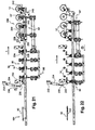
- the transfer devices 50 and 50 ' are capable of transferring a group of preforms 14 and a group of containers 12, each transfer device 50, 50' respectively comprising four modules or carriages capable of simultaneously transferring a group of four preforms 14. or four containers 12.
- the first transfer device 50 comprises connecting means able to vary the longitudinal spacing between the modules from the first spacing PAS1 corresponding to the longitudinal spacing between the preforms 14 during loading to a second gap, said PAS2, greater than the first PAS1 and corresponding to the necessary longitudinal spacing between the preforms 14 to allow their unloading in the mold 40 (see figure 1 ).
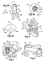
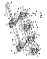
- the transfer device 50 comprises gripping means consisting of at least one clamp 54 adapted to cooperate with a portion of a preform 14 or a container 12 so as to allow the transfer of said preform or said container, in particular between the units or stations of the linear installation of manufacture.
- the clamp 54 is constituted by two levers 54a, 54b which extend generally in the transverse direction, orthogonal to the longitudinal direction of displacement indicated by the arrow L on the figure 1 , the levers 54a, 54b of the clamp 54 extending in a substantially horizontal plane which is in particular determined with respect to the position of the neck 22 of the preform 14.
- the levers 54a, 54b are mounted articulated around a vertical axis B between an open position ( figure 8 ) and a closed position ( figure 9 ) of the clip 54.
- the right lever 54b comprises a shaft 56 which extends vertically upwardly from the lever and around which a complementary cylindrical bush 58 is mounted which is provided by the other left lever 54a so that the shaft and the bushing constitute an articulation along the vertical axis B between the levers 54a, 54b.
- the clamp 54 comprises elastic return means 60 of the levers 54a, 54b towards said closed position.
- the elastic return means 60 of the levers 54a, 54b are constituted by a spring which, working in compression, is here mounted at the rear transverse end of the clamp 54.
- each lever 54a, 54b has at its rear end a wing, respectively 62a and 62b, which transversely oriented, extends vertically upwards from the horizontal reference plane comprising the levers.
- each wing 62a, 62b has on its vertical vertical face 64a, 64b, a centering pin 66 for the spring constituting the elastic return means 60 of the levers 54a, 54b, each pin 66 penetrating into the end turns of the spring .
- the spring is supported at each of its ends on the internal vertical faces 64a, 64b of each wing 62a, 62b by means of which the spring biases the rear end of the levers 54a, 54b in spacing which causes, at the opposite, transversely, the approximation of the front end of each lever 54a, 54b forming the portion of the clamp 54 for performing the gripping, also commonly called jaws or jaws.
- the elastic return means 60 of the levers 54a, 54b could be arranged transversely between the articulation (shaft 56, bushing 58) of the levers or between the articulation and the front end forming jaws and the elastic return means 60 which may be any other equivalent equivalent.
- the levers of the clamp 54 respectively comprise, in front of the hinge (shaft 56, sleeve 58), a generally flat upper surface 68 on which are intended to be mounted elements which will be described in detail later.
- each lever of the clamp 54 is made in two distinct parts, the rear parts of the levers comprising the hinge 56, 58 and the elastic return means 60 and the front parts forming the two jaws of the clamp 54, hereinafter the jaws 70.
- Each front portion of the lever forming one of the two jaws 70 is attached to attachment to the front end of the rear portion of the lever 54a, 54b corresponding, for example by means of fasteners 72, such as screws .
- each jaw 70 internally comprises a vertical face 74 which, intended to cooperate with a portion of the neck 22 of the preform 14, has a generally curvilinear profile complementary.
- the vertical faces 74 of the jaws 70 internally define a generally circular opening 76 having a diameter slightly smaller than that of the neck 22 of the preform 14 to be transferred.
- the jaws 70 of the clamp 54 are intended to cooperate with the groove 32 of the neck 22 of the preform 14 and the thickness of the jaws 70 is determined so that the portion adjacent to each vertical face 74 can engage at least partially between the collar 28 and the bead 30, the jaws 70 of the clamp 54 thus tightening the neck 22 of the preform and being positioned above the collar 28.
- the jaws 70 of the clamp are positioned below the radial collar 28 which, in the closed position of the clamp 54, bears on an adjacent portion of the face upper horizontal 78 of each of the jaws 70, the jaws 70 then exerting or not a clamping force of the neck 22.
- Such a variant corresponds in particular to the positioning of the transfer clamps according to the state of the art FR-A-2879179 supra.
- the gripping of the neck 22 at the groove 32 requires control and precision during the loading and unloading operations so that the clamp 54 does not damage either the flange 28 or the bead 30 adjacent.
- the transfer device 50, 50 ' is more particularly intended to equip an installation 10 linear, as previously described and represented in figure 1 , in which the thermal conditioning unit 34 of the preform 14 comprises a furnace 36, said preferentially heated.
- the preform 14 which is transferred downstream in order to carry out the blow molding operation would no longer be in the determined angular position, referred to as a reference, during its unloading, which corresponds to its introduction into the mold. mold.
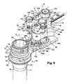
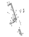
- the transfer device 50, 50 comprises a mechanism 80 for selectively controlling the opening and closing of the clamp 54 around the neck 22 of the preform 14 or the container 12 during the loading and unloading operations. unloading.
- the transfer device 50 makes it possible, in particular, to transport each preform 14 from the outlet of the oven 36 to the mold 40 by precisely maintaining each of the preforms in said reference angular position.
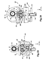
- the mechanism 80 comprises at least one spacing member 82 of the levers 54a, 54b intended to be driven by a driving rod 84 which is pivotally mounted around a shaft 86, the driving rod 84 of the body spacing 82 having at least one free end 88 which is adapted to cooperate with first actuating means 90 ( figure 10 ) intended to cause the opening of the clamp 54 against the elastic return means 60 of the levers, said first elastic return means.
- the mechanism 80 comprises a plate 96 for mounting the various components, in particular that of the spacer member 82, its drive rod 84 and locking means 92.
- the spacer 82 has been shown in detail in FIGS. 3A to 3C .
- the spacer member 82 extends vertically about a principal axis C shown vertical.
- the spacing member 82 has an upper portion constituted by a vertical rod forming the shaft 86 around which is pivotally mounted the drive rod 84, the rotation without play between the driving rod 84 and the spacer 82 is formed by cooperation of forms.
- the shaft 86 comprises at its upper end two flats 98, said upper end of the shaft 86 being received with interposition of intermediate elements in a complementary housing (not shown) that comprises the driving rod 84.
- the shaft 86 is integral with the drive rod 84 and adapted to cooperate with a portion of the spacer 82 for its drive in rotation about the vertical axis C.
- the spacer member 82 has at its lower end a spacer 100 which is able to act on the levers 54a, 54b.
- the spacer 100 here has the form of a rectilinear wall extending vertically downwards from the lower face of an intermediate portion 102 of the spacer member 82.
- the intermediate portion 102 generally has a horizontal disk shape which connects the spacer 100 and the lower end of the shaft 86 and which extends circumferentially around the shaft 86.
- the rear portion 104 of the disk constituting the intermediate portion 102 is beveled thus forming a profile "V", which is not symmetrical here, so that the spacer 82 does not interfere, when pivoting around of the vertical axis C, with other adjacent components such as the articulation formed by the shaft 56 and the sleeve 58 of the levers of the clamp 54.
- the spacer 100 comprises, laterally on either side, a flat vertical side face, respectively 106a of the left side and 106b of the right side, which are each intended to cooperate with an associated roller 108a, 108b.
- rollers 108a, 108b are respectively mounted, for example by means of rings 107 and screws 109a and 109b, in complementary holes 111 that has in its upper horizontal face 68 each of the levers 54a, 54b.
- the spacer 100 of the spacer member 82 is, in the open position of the clamp 54, to the front supported by a portion of its side face 106b against the right roller 108b and, back, in supported by a part of its lateral face 106a against the left roller 108a so that when the spacer member 82 is rotated towards the closed position each of the rollers 108a, 108b will roll against the lateral face 106a, 106b which is associated with it, in a direction opposite to that of the other pebble.
- a portion of the lateral face 106a of the spacer 100 abuts against abutment means 110, constituted for example by a pin which is arranged in front of the roller 108a and which is mounted on the left lever 54a, for example, mounted in force in a hole that includes the upper horizontal face 68 of the lever.
- the plate 96 has, at its transverse front end, an orifice 112 which is traversed by the shaft 86 so that the spacer 82 is mounted below the plate 96 while the driving rod 84 is arranged. above.
- the plate 96 comprises, behind the orifice 112 for passage of the shaft 86 of the assembly formed by the spacer member 82 and the driving rod 84, another orifice 114 which is traversed in all or part by the shaft 56 carried by the lever 54b to form the articulation of the levers 54a, 54b, the clamp 54 about the vertical axis B.
- the orifices 112, 114 are substantially aligned in the transverse direction so that the axes of rotation B and C, respectively of the assembly formed by the spacer 82 and the driving rod 84 and levers 54a, 54b , are included in the same vertical plane of transverse orientation.
- the plate 96 comprises, behind the orifice 114, a groove 116, transverse, in which is introduced the front end of a transverse rail 118 which is fixed to the plate by screwing, the rail 118 having as the bottom of the groove 116 two holes 119 intended to allow the passage of the screws 120.
- the rail 118 belongs to transmission means capable of allowing the displacement of the subassembly formed by the clamp 54 and its mechanism 80 in the transverse direction, orthogonal to the longitudinal direction L of displacement, transmission means which will be described later.
- the plate 96 has, on the left side, adjacent to the groove 116 for fixing the rail 118, on the one hand a bore 122 for mounting a cam follower 124 which will also be described later in connection with the means of transmission of movement to which it belongs and which are able to allow a displacement in said longitudinal direction L of displacement and, secondly, a housing 126 having a cavity 128 open transversely to each front and rear end which is intended for mounting second means resilient return which will be described hereinafter in relation to the locking means 92 to which they belong.
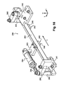
- the locking means 92 comprise a locking pin 130 which is mounted movably between the retracted position and the locked position.
- the locking pin 130 is biased towards the locked position by second elastic return means 132 which are for example constituted by a second coil spring working in compression.
- the spring constituting the second elastic return means 132 for elastic return of the locking pin 130 is mounted inside the cavity 128 of the housing 126 by means of a plurality of means 133, 135, 137 including a rod support 133 having at its front end a bearing head 134 adapted to cooperate with the locking pin 130 to exert, transversely forward, a return force to the locked position.
- the means for mounting the spring constituting the second resilient return means 132 further comprise a bushing 135 and another support rod 137 which can be screwed together at its front end with the support rod 133 beforehand. in order to put with the sleeve 135 the spring constituting the second elastic return means 132 under stress.
- the locking pin 130 cooperates with a complementary notch 136 to immobilize the assembly formed by the spacer member 82 and the drive rod 84 against the spring forming the first elastic return means 60.
- the locking means 92 comprise a control element 138 of the closure of the clamp which is adapted to cooperate selectively with the first actuating means 90 to cause the unlocking.
- the first actuating means 90 are able to act selectively on the control element 138 to cause the unlocking by moving, against the second spring forming the second elastic return means 132, the locking pin 130 of the locked position in the retracted position so that, releasing the assembly formed by the spacer member 82 and the drive rod 84, the spring forming the first elastic return means 60 levers 54a, 54b causes the automatic closure of the clip 54.
- control element 138 of the closure and the locking pin 130 are mounted integral with the free end of a support arm 140 which is pivotally mounted at its other end 142 in the form of a sleeve, around a vertical axis coinciding with the vertical axis B of the articulation 56, 58 of the levers, via elements 144.
- the elements 144 forming the vertical axis, through which the end 142 of the support arm 140 pivots about the vertical axis B, are mounted in the orifice 114 of the plate 96.
- the free end 146 of the support arm 140 has a bearing face 148, here disposed vertically at the rear of the free end 146, adapted to be biased by the spring constituting the second elastic return means 132 of the locking means 92 via the vertical front face of the support head 134.
- the bearing surface 148 cooperates directly with the vertical front face of the support head 134 which is biased transversely forward the spring constituting the second elastic return means 132 via the sleeve 135.
- the bearing surface 148 is constituted by a hemispherical surface that comprises the head 150 of a pin 152 shaped "pushpin" comprising a transverse rod 154 which, integral with the head 150, is received transversely in a complementary housing 156 of the free end 146 of the support arm 140.
- the complementary housing 156 extends generally transversely across the free end 146 of the support arm 140, from the rear vertical surface 157 against which the face of the head 150 opposite the hemispherical surface constituting the bearing face 148 is support, to debouch here at the front of the arm.
- the hemispherical surface constituting the bearing surface 148 of the pin 152 makes it possible to maintain a permanent contact with the front face of the support head 134 when the support arm 140 pivots about the axis B between its corresponding extreme positions. locked and unlocked positions.
- the locking pin 130 is for example constituted by an annular ring and the control element 138 of the closure of the clamp 54 by a roller.
- the locking finger 130 and the roller forming the control element 138 are mounted on a support rod 158 which extends vertically and which passes through a complementary hole 161 at the free end 146 of the support arm 140.
- the support rod 158 is mounted so that the roller forming the control element 138, which is mounted at the upper end of the support rod 158, extends vertically above the support arm 140, while the locking finger 130, which is mounted at its lower end, extends vertically below the support arm 140.
- a nut 159 is attached to the lower end of the support rod 158 to maintain in position the roller forming the control element 138 and the locking pin 130.
- the driving rod 84 of the spacer member 82 has at its free end 88 a control element 160 of the opening of the clamp 54 which is able to cooperate selectively with the second actuating means 94.
- the control element 160 of the opening of the clamp 54 is capable, when it is urged by the second actuating means 94, to cause the displacement of the spacer 82, hence the spacer 100 from the passive position to the active position corresponding to the open position of the clamp 54.
- the control element 160 of the opening of the clamp 54 is constituted by a roller which is mounted on a vertical support rod 162 which passes through a hole 164 of the free end 88 of the connecting rod 84.
- a washer 163 is here interposed between the roller constituting the control element 160 and the upper face of the connecting rod 84 surrounding the hole 164; a nut 165 is for example attached to the end of the vertical support rod 162 to hold the assembly.
- the roller constituting the opening control control element 160 of the clamp extends over the drive rod 84, generally in a horizontal plane such as the roller forming the control element 138.
- the driving rod 84 has a free end 88 carrying the roller constituting the control element 160 of closure of the clamp 54 and an opposite end 166 which is articulated around the vertical axis C common with the vertical shaft 86 of the spacer 82.
- the mechanism 80 comprises a lever 170 comprising an end 168 which is connected to the articulated end 166 of the drive rod 84 so that said lever 170 is rotatably connected to the driving rod 84, that is to say displacements around the axis C between the active and passive positions of the assembly formed by the spacer member 82 and the driving rod 84.
- the notch 136 is made directly in the end 166 of the drive rod 84 or in the spacer 82, for example in the shaft 86 or the disk 102.
- the notch 136 has a complementary "V" profile of the locking finger 130 formed by the ring, the profile of the notch 136 having a rear vertical face 174 and a vertical front face 176 with which cooperate a portion of the finger when the locking means 92 is in the locked position, the finger enters the notch 136.
- the lever 170 comprises a notch 136 forming a complementary notch of the locking pin 130 and which is disposed at its free end 172 which is opposite the end 168, extends radially from the drive rod 84 which it is united.
- the notch 136 does not have a "V" profile with faces 174, 176 but a face 175.
- the locking pin 130 cooperates with the surface delimited by the faces 174, 176, respectively 175, of the notch 136.
- the lever 170 comprises a guide surface 178 which is adjacent to the vertical front face 176 of the notch 136 and against which the locking pin 130 bears when the locking means 92 are in the retracted position.
- the locking pin 130 has an outer annular surface 180 which is here in permanent contact with the surface formed by the faces 174, 176 or the guide surface 178 according to the position occupied by the locking means 92, that is to say say the locked position or the retracted position.
- FIGS. 8 and 9 a clamp 54 with the assembly of the assembled mechanism 80 which respectively illustrate the locked position corresponding to the open position of the clamp 54 and the retracted position corresponding to the closed position of the clamp 54.
- the locking means 92 To close the clamp 54, the locking means 92 must be moved from the locked position to the retracted position in order to release the assembly formed by the driving rod 84 and the spacer 82 which is therefore likely to be moved from the active position to the passive position under the action of the elastic return force exerted by the elastic return means 60 on the levers 54a, 54b and therefore on the spacer 100 via the rollers 108a, 108b.
- the roller forming the control element 138 is biased transversely rearward by the first actuating means 90 so that the transverse force F of closure applied, from front to rear, on this roller causes the pivoting of the support arm 140 in the clockwise direction about the axis B and against the spring constituting the second elastic return means 132 and thus causes the displacement of the locking pin 130, integral with the roller and of the support arm 140, out of the notch 136.
- the outer annular surface 180 of the locking pin 130 will travel the rear vertical face 174 of the notch 136 to exit the notch 136 to simultaneously come into contact with the front vertical face 176.
- the roller constituting the control element 160 of the opening of the clamp 54 is biased by the first actuating means 90 so that the force applied on this roller causes the driving rod 84 to pivot about the axis C in the anti-clockwise direction, that is to say the displacement of the spacer member 82 against the elastic return means 60 of the levers, from the passive position to the active position.
- the locking pin 130 travels, from front to rear, the guide surface 178 forming a ramp until the locking pin 130 switches into the notch 136 in the locked position: this tilting occurs when the active position is reached simultaneously by the drive rod 84 and the spacer 82, and has the consequence of placing in position open of the clamp 54.
- the transfer device 50 is more particularly intended to equip, as illustrated in FIG. figure 1 , a linear type installation 10 for the manufacture of containers 12 from preforms 14, the installation 10 comprising mainly the thermal conditioning unit 34 and the molding unit 38.
- the first transfer device 50 of the installation 10 comprises a group of modules 182 able to simultaneously transfer a group of preforms 14 from a loading zone 184 situated at the outlet of the furnace 36 of the thermal conditioning 34 to the mold 40 of the molding unit 38.
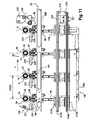
- FIG. 10 an exemplary embodiment of a transfer device 50 comprising a group of four modules 182 able to simultaneously transfer a group of four preforms 14.
- each module 182 of the first transfer device 50 of the preforms 14 comprises a gripper 54 whose opening and closing are selectively controlled by means of a mechanism 80, described above, by which the transfer is assured. of each preform 14 by maintaining it in a given angular position since loading until unloading in the mold 40.
- At least the modules 182 of the first transfer device 50 of the preforms are interconnected by means of connecting means 186 adapted to vary the longitudinal spacing separating two successive modules 182, between the first spacing, said PAS1 corresponding to a contracted configuration of the modules illustrated by the figure 10 and the second spacing, called PAS2, corresponding to a deployed configuration of the modules illustrated by the figure 11 .
- a module 182 of the transfer device 50 of the preforms 14 comprising a preferred embodiment of the connecting means 186 intended to allow the variation of the spacing PAS1 to the pitch PAS2 and vice versa.
- Such connecting means 186 are advantageously similar to those described in the document EN-A1-2.879.179 filed in the name of the applicant and to which reference will be made for a detailed description of the connecting means 186 and their operation.
- connection means 186 comprise a lever 188 rotatably mounted on one of the modules 182 about a vertical axis D, substantially perpendicular to the longitudinal direction L of displacement, this lever 188 comprises two parts respectively a left rod 188a and a right rod 188b which extend on either side of the axis D.
- the left rod 188a of the lever is provided at one free end 190 with a first finger 192, for example a roller, able to circulate in a groove 194 arranged transversely on the other of the modules 182.
- the right connecting rod 188b of the lever is provided at one free end 196 with a second finger 198, for example a second roller, and the installation 10 comprises a bearing structure 200 comprising a groove 202, arranged longitudinally, in which the second finger moves 198.
- the groove 202 comprises a downstream section 202A and an upstream section 202C which, substantially parallel to the longitudinal direction L of displacement, are interconnected by an intermediate section 202B, which is curved and substantially oblique, forming an angle ⁇ which is variable with respect to the direction longitudinal L displacement.
- the installation 10 comprises at least first transmission means 204 capable of moving in the longitudinal direction the first transfer device 50 of the preforms and second transmission means 206 able to move in a transverse direction, orthogonal to the longitudinal direction L of displacement in the linear installation, the clamps 54 of the modules 182 of the first transfer device 50 of the preforms so as to proceed to the loading or unloading of the preforms 14.
- the first transmission means 204 preferably comprise two rails, respectively before 210a and rear 210b, which extend longitudinally, parallel to the longitudinal direction L of displacement, and which are integral with the support structure 200 of the installation 10, each module 182 of the transfer device 50 of the preforms 14 comprising two slides 212a, 212b through which the modules 182 are attached to the rails 210a, 210b.
- the first transmission means 204 comprise associated drive means (not shown) such as a belt coupled to a motor and fixed to at least one of the modules 182, for example by means of a flange. , so as to move the group of modules 182 of the transfer device 50 of the preforms 14 in the longitudinal direction L.
- associated drive means such as a belt coupled to a motor and fixed to at least one of the modules 182, for example by means of a flange.
- the second transmission means 206 comprise at least one actuator, such as an electric motor, capable of selectively controlling, in the transverse direction, the displacement of the rail 118 secured to the plate 96 of each module 182, so that the rail 118 slides telescopically between an extreme rear position illustrated in FIG. figure 12 and an extreme forward position illustrated to the figure 13 , the displacement of the rail 118 causing the advance or retreat of the clamp 54 and the mechanism 80 relative to the carrier structure 200 and the first transmission means 204.
- actuator such as an electric motor
- the second transmission means 206 comprise at least one actuator constituted by any appropriate means, for example a pneumatic or hydraulic jack, etc.
- the installation 10 comprises, downstream of the first, the second transfer device 50 'which comprises a mechanism 80' similar to the mechanism 80 described above but which is intended to transfer downstream the containers 12, here at the same time the group of four containers 12 manufactured by the molding unit 38 and having a group of four modules 182 '.
- the mechanism 80 'of the transfer device 50' of the bottles 12 differs from the mechanism 80 only in that the arrangement of the components is inverted with respect to a vertical plane of transverse orientation.
- control element 138 of the closure is on the left or the downstream side and the control element 160 of the opening is on the right or the upstream side whereas in the case of the mechanism 80 'the control element 138' of the closure is on the right or the upstream side and the control element 160 'of the opening is on the left or the downstream side in the longitudinal direction L of displacement.
- the carrying structure 200 of the installation 10 comprises transmission means able to move the second transfer device 50 'of the containers 12 in the longitudinal direction L.
- said transmission means of the second transfer device 50 ' are constituted by the first transmission means 204 of the first transfer device 50 of the preforms.
- the transfer device 50 of the preforms 14 and the transfer device 50 'of the containers 12 are capable of working perfectly synchronously during displacements in the longitudinal direction L.
- pooling still makes it possible in general to reduce the manufacturing costs of the installation 10 and to simplify operation and maintenance operations.
- the carrier structure 200 of the installation 10 comprises second transmission means 208 able to move in a transverse direction, orthogonal to the longitudinal direction L of movement, the clamps 54 'of the modules 182' of the second transfer device 50 containers 12 so as to proceed with the loading or unloading of the containers.
- the four modules 182 'forming the transfer device 50' are integral with a first longitudinal support 214, such as a support bar, which is fixed on the rear part of the plates 96 'of each module 182'.
- the modules 182 ' are separated from each other by a fixed longitudinal distance corresponding to the spacing PAS2, that is to say the longitudinal spacing between the axes A of two successive containers 12.
- connecting means 186 which allowed to vary the spacing between the modules as for the first transfer device 50.
- the transfer device 50 ' comprises two pairs of two sliders 212'a, 212'b able to cooperate with the rails 210a, 210b of the supporting structure 200 and which are respectively associated with the first and third modules 182'.
- the slides 212'a and 212'b are integral with the upper horizontal face of a second rear longitudinal support bar 216 and on the lower horizontal face of which are fixed the second transmission means 208 of the transfer device 50 '.
- the second transmission means 208 comprise at least two actuators 208a, 208b capable of controlling the telescopic deployment of the two rails 118 'associated with the first and third modules 182'.
- the four modules 182 'being in particular integral with the longitudinal support 214, the transmission means 204 and 208 are reduced and here associated with the first and third modules 182' without it being necessary to provide means for each of the modules as this was the case for the modules 182 of the transfer device 50.
- the rear longitudinal support bar 216 has on its upper horizontal face flanges 218 for fixing a belt (not shown) advantageously adapted to be driven by a motor.
- the rear longitudinal support bar 216 comprises an upstream free end 220 intended to be connected to the transfer device 50 of the preforms 14, in particular to the fourth module 182 located the most downstream, for example by bolts 221.
- first and second actuating means 90 and 94 for selectively controlling the opening and closing of the grippers 54 and 54 'of the transfer devices 50 and 50'.
- the actuating means 90, 94 fitted to the installation 10 are mounted integral with the supporting structure 200 and are therefore not embedded with the moving parts longitudinally and transversely of each of the transfer devices 50, 50 '.
- the first actuating means 90 are intended to be arranged at the loading zone 184 at the outlet of the oven 36 so as to cooperate simultaneously with the control element 138 for closing each clamp 54 to selectively control the closure jaws 70 of the clamp when the jaws 70 are in a determined position around the neck 22 of each preform 14 to be transferred.
- the first actuating means 90 are mounted integral with the support structure 200 via a support 91 and are constituted by a longitudinal bar having a vertical actuating face 222.
- the second actuating means 94 are arranged longitudinally at the level of the molding unit 38 so as to cooperate with the opening control element 160 of each clamp 54 to selectively control the opening of each clamp of the first transfer device 50, when the preforms 14 are immobilized in the mold 40 without being able to leave the reference angular position.
- the second actuating means 94 arranged at the level of the molding unit 38 are also able to cooperate with the control element 138 'of the closure of each clamp 54' of the second transfer device 50 ', so as to selectively control the closure of each clamp 54 'around the neck of the container 12 manufactured to be transferred to the unit 52 downstream, for example to a filling unit.
- the second actuating means 94 are movably mounted between a first actuating position and a second actuating position, so as to cooperate selectively with the control element 138 'of the closure of each clamp of the second actuating device. transfer 50 'of the containers 12 in the first position and with the control element 160 of the opening of each clamp 54 of the first transfer device 50 of the preforms 14 in the second position.
- the second actuating means 94 are constituted by members 224, here four in number as the modules, interconnected by a longitudinal bar 225 hooking.
- the four members 224 are mounted on the bar 225 with a determined spacing between two consecutive members 224 and each member 224 has a vertical control face 226 (see FIG. figures 17 and 23 ) which extends below the bar 225 in a separate horizontal plane.
- the bar 225 carrying the members 224 is articulated at each of its longitudinal ends by means of a first connecting rod 228 and a second connecting rod 230 respectively arranged at the downstream and upstream ends of the bar 225.
- the first connecting rod 228 has one end which is pivotally mounted about a vertical axis on the downstream end of the bar 225 and whose other end is pivotally mounted on a portion of support means 232 which, integral with the supporting structure 200 of the installation 10, are intended to allow the mounting of the second actuating means 94.
- the second connecting rod 230 has an "L" shape and comprises a link 231 which is mounted as the first connecting rod 228.
- the link 231 has one end which is pivotally mounted about a vertical axis on the upstream end of the bar 225. and whose other end is pivotally mounted on another part of the support means 232.
- the second connecting rod 230 comprises another rod 233, forming the other bar of the "L", one end of which is secured, like the rod 231, to the upstream end of the bar 225 and whose other free end is suitable for cooperate with actuating means, such as at least one actuator 234.
- the actuator 234 is for example constituted by a pneumatic cylinder, in a hydraulic variant, comprising an actuating rod 236 whose free end is articulated on the free end of the link 233 of the second connecting rod 230.
- the actuator 234 is controlled so as to selectively move the rod 236 of the cylinder between a retracted position and an extended position in which the rod 236 extends out of the cylinder body of the cylinder.
- each member 224 In the first operating position of the second means 94, each member 224 is intended to cooperate via its vertical control face 226 with the control element 138 'closing each clamp 54' of the second transfer device 50 'of the containers 12, while in the second position, each member 224 is intended to cooperate through its vertical control face 226 with the control element 160 opening each clamp 54 of the first transfer device 50 of the preforms 14.
- the actuator 234 is an electric motor adapted to bias the second connecting rod 230 to cause a translational movement in the longitudinal direction of the bar 225 and members 224.
- an actuator 234 of the electric motor type allows in particular to eliminate the risk of leakage inherent in the use of a pneumatic or hydraulic fluid.
- the installation 10 comprises third actuating means 238 shown in FIG. figure 16 which are arranged longitudinally at the level of the unit 52 and are mounted integral with the supporting structure 200 by means of support elements 240, 241.
- the third actuating means 238 are able to cooperate with the transfer device 50 'of the containers 12, in particular to selectively control the opening of the clamps 54' in order to release the collars 22 of the containers 12 manufactured from the mold 40.
- the third actuating means 238 comprise actuating members 242, four in number such as the modules 182 ', which are connected by a hooking bar 244 which extends longitudinally parallel to the direction L of displacement .
- Each actuating member 242 has a vertical actuating face 246 adapted to cooperate with a control element 160 'of the opening of the clamp 54'.
- the bar 244 is movably mounted via a first link 248 and a second link 250 which are respectively substantially transverse orientation.
- the first link 248 is pivotally mounted at one end on a support member 240, about a vertical axis, and is connected at its other end by a vertical connecting member 252 to the downstream portion of the bar 244.
- the second link 250 is pivotally mounted at one end to another support element 241, about a vertical axis, and is connected at its other end by a vertical connecting element 253 to the upstream portion of the bar 244.
- the bar 244 carrying the actuating members 242 is thus articulated with respect to the support elements 240, 241 integral with the support structure 200 and is capable of moving in translation in the longitudinal direction L between a first position and a second position. , said actuation corresponding to the opening control of the clamps 54 '.
- the third actuating means 238 comprise at least one actuator 254 which is mounted integral with an element of support 243.
- This actuator 254 is for example constituted by a pneumatic cylinder comprising an actuating rod 256 that can be controlled in displacement between a retracted position and an extended position.
- the free end of the actuating rod 256 is adapted to cooperate with the end of the second link 250 to cause, via the connecting element 253, when the rod is moved from its retracted position to the at its extended position, the displacement of the bar 244 carrying the actuating members 242.
- each vertical face actuation 246 of an actuating member 242 cooperates with the control element 160 'of the opening of the clamp 54' of each module 182 'of the transfer device 50' to discharge the containers 12 manufactured.
- each cam follower 124 of a module 182 is received in a rail having a complementary cam path 258 which extends rectilinearly along the longitudinal direction L of displacement but is capable of moving transversely with the transfer means 50 of the preforms 14.
- each cam follower 124 'of a module 182' is received in a rail having a complementary cam path 260 which extends rectilinearly along the longitudinal direction L of displacement but which is capable of to move transversely with the transfer means 50 'of the containers 12.
- the figure 17 represents the linear installation in the initial state corresponding to the beginning of the transfer cycle of which will be described hereinafter the first step, referred to as the loading of the preforms, by comparison of the Figures 17 and 18 .
- a group of four preforms 14 is first brought from the upstream out of the oven 36 of the thermal conditioning unit 34 to the loading zone 184 downstream, to be loaded by the device transfer 50.
- the preforms 14 are aligned in the longitudinal direction L of displacement, spaced longitudinally from each other by a spacing PAS1 determined here by the spacing between the rollers 44 and are each in the determined angular reference position. by the preferential heating operation carried out in the oven 36.
- the transfer device 50 is initially positioned longitudinally vis-à-vis the loading zone 184 pending the arrival of such a group of preforms 14, the position of each module 182 being determined so as to be in coincidence with the preform 14 associated with it in the loading zone 184.
- the second transmission means 206 preferably constituted by actuators of the electric motor type, are controlled so as to move each of the modules transversely and simultaneously. of transfer device 50 to the front, the transverse displacement forward of the clamps being advantageously synchronized with the displacement of the preforms in the longitudinal direction.
- the preforms move continuously in the oven 36 so that the control parameters of the displacement of the transfer device 50 are determined according to the operating parameters (speed, etc.) of the oven.
- the first transmission means 204 are stationary so that the slides 212a, 212b of each module 182 remain in the initial position relative to the rails 210a, 210b.
- Each actuator constituting the second transmission means 206 is controlled so as to cause the forward movement of the rail 118 of each module 182 at the end of which are mounted the clamp 54 and its mechanism 80 for opening and closing control .
- Each rail 118 extends telescopically from its rearmost position shown in FIG. figure 17 until reaching the extreme forward position represented at figure 18 .
- each clamp 54 is initially held in the open position by the locking means 92 against the elastic return means 60 of the levers.
- each closing control element 138 will come to the end of the stroke in contact with the vertical operating face 222 forming first actuating means 90 as is illustrated by the figure 23 .
- This closing force F causes the control element 138 to retreat and consequently the displacement of the support arm 140 which carries the locking pin 130, which then pivots in the clockwise direction about the vertical axis B.
- the force F applied by the first actuating means 90 to the control elements 138 of each module 182 thus causes the locking means 92 to move, against the elastic return means 132, from the locked position to the in the retracted position.
- the locking pin 130 When the retracted position is reached, the locking pin 130 is outside the notch 136 and the assembly formed by the spacer 82 and the drive rod 84, biased by the elastic return means 60, moves towards its passive position which is reached when the spacer 100 is in abutment against the pin constituting the stop means 110.
- first actuating means 90 are positioned so that the clamps 54 initially in the open position each engage around the necks 22 of the preforms 14 before the solicitation of the closing control elements 138 by the vertical face of the actuation 222 of the first means 90 does not cause the automatic closing by unlocking.
- the jaws 70 of each clamp 54 are automatically closed around the neck 22 of the preform 14, without the reference angular position of the preform 14 being able to be closed. modified during this loading operation and having the assurance by the clamping force exerted by the jaws 70 on the neck that this reference position will be retained during the transfer to the molding unit 38.
- the container manufacturing installation 10 is of the type comprising a molding unit 38 in which the previously injected preform 14 is heated in the furnace 36 and then blow-molded or stretch-blow molded in one operation so as to directly obtain a final container 12 shaped.
- the final container 12 may be obtained according to a manufacturing method comprising several distinct stages of blow molding or stretch-blow molding so as to transform the preform 14 into at least one intermediate container (not represented) before obtaining of the final container.
- the first transmission means 204 are controlled so as to move, in the longitudinal direction L of displacement, the transfer device 50 of the preforms 14 and the transfer device 50 'of the containers via means common drive (not shown), such as a belt driven by a motor.
- the transfer device 50 is moved downstream releasing the loading zone 184 for feeding the next set of preforms and the transfer device 50 'is moved to be positioned longitudinally in register with the mold 40 (not shown) of the molding unit 38 so that the clamps 54 'modules 182' are aligned transversely with the necks 22 of the containers 12 they are intended to transfer downstream to the unit 52.
- the actuators 208a, 208b forming the second transmission means 208 are then commanded to deploy transversely forward the rails 118' which are telescopically displaced from the rear position of rest shown. to the figure 17 or 18 until reaching the position before seizure represented at the figure 19 .
- the actuating member 224 then urges the control element 138 'with a transverse force F directed towards the rear which simultaneously causes the recoil of the control element 138' and the pivoting around the axis B, in the anti-clockwise direction of the support arm 140 'whose control element 138' is integral and which also carries the locking pin 130 '.
- the applied force F causes the unlocking of the locking means 92 by moving the finger 130 'locking out of the notch 136', that is to say towards the retracted position.
- the unlocking operation releases the assembly formed by the spacer member 82 'and the drive rod 84' which, biased by the elastic return means 60 '(such as a spring) levers 54'a, 54'b , then closes automatically around the collars 22 of the containers 12.
- the elastic return means 60 ' such as a spring
- the four containers 12 are then loaded by their respective necks 22 into the clamps 54 'and are able to be transferred downstream.
- the transverse difference between the front end of the two jaws 70, 70 'of each clamp 54, 54' is advantageously greater than the diameter of the necks 22 of the preforms 14 or containers 12 so that the clamps 54, 54 ' in the open position can engage transversely without contact around the necks 22 and that the necks 22 are positioned generally in the center of the opening 76, 76 'when the closure of the jaws of each clamp 54, 54' is triggered.
- the first transmission means 204 are controlled to move longitudinally in the direction L, on the one hand the transfer device 50 'of the molding unit 38 to the unit 52 located downstream and, on the other hand, the transfer device 50 to the molding unit 38.
- the displacements of the two transfer devices 50, 50 ' are simultaneous and perfectly synchronous because the longitudinal support bar 216 of the transfer device 50' is connected by its upstream free end 220 to the adjacent module 182 of the transfer device 50 and because of the use of common drive means (belt, motor not shown).
- the transfer device 50 is moved longitudinally from the intermediate position it occupied to the figure 19 at the position he occupies at the figure 20 , in which position the preforms 14 are able to be discharged into the mold 40 for blow molding to obtain the containers 12.
- the spacing between the modules 182 of the transfer device 50 is modified to reach the value of the second spacing PAS2 through the connection means 186 described above.
- modules 182 of the transfer device 50 are automatically passed, during the transfer downstream, their initial contracted configuration ( figure 10 ), corresponding to the first spacing PAS1 to the final deployed configuration ( figure 11 ) corresponding to the second gap PAS2.
- the position occupied by the transfer device 50 'on the figure 20 at the unit 52 corresponds to the position in which the containers 12 are intended to be unloaded for filling or evacuation.
- the fourth stage of the cycle consists mainly of selectively controlling, on the one hand, the opening of the clamps 54 of the transfer device 50 to unload the preforms 14 and, on the other hand, the opening of the clamps 54 'of the transfer device 50'. to unload containers 12.
- the two half-molds 46a, 46b of the mold 40 are displaced in translation towards the closed position in which the body 16 of each preform 14 extends vertically inside a volume defined by the meeting of complementary half-impressions 48.
- the operation of unloading the preforms 14 by opening the clamps 54 is performed when each preform 14 is immobilized by means such as the mold 40 and / or a portion of the associated blowing means (not shown) so that, when opening the clamps 54, the reference angular position of each preform 14 transferred can not be modified.
- the actuator 234 is controlled by the second actuating means 94 so as to cause the downstream displacement of the bar 225 carrying the members 224 in a translational movement in the longitudinal direction L, as was previously described for the figure 15 .
- the members 224 of the second actuating means 94 move from the first actuating position in which each member 224 cooperates via its vertical control face 226 with the control element 138 'closing each clamp 54 of the second transfer device 50 'of the containers 12 to the second actuating position in which each member 224 cooperates via its vertical control face 226 with the opening control element 160 of each clamp 54 of the first transfer device 50 of the preforms 14.
- the members 224 When the second actuating means 94 reach said second actuating position, the members 224 cooperate via their respective vertical control face 226 with the opening control element 160 of each clamp 54 of the first actuating device. transfer 50 of the preforms 14 as illustrated by the figure 25 .
- Each member 224 then urges the control element 160 to open with an opening force O which causes the pivoting of the drive rod 84 around the vertical axis C, causing the spacer 82 to rotate. and, accordingly, the spacer 100 from the passive position to the active position which corresponds to the open position of the clamp 54.
- the lever 170 is driven with the assembly formed by the spacer member 82 and the driving rod 84, so that the locking pin 130 of the locking means 92, initially in the retracted position, traverses the guide surface 178 until it penetrates into the notch 136 corresponding to the locking position in which the locking finger 130 holds the clamp 54 in the open position against the elastic return means 60, such that a spring, levers 54a, 54b.
- the unloading operation of the containers 12 is obtained in a similar way by controlling the actuator 254 of the third actuating means 238 shown in FIG. figure 16 and previously described.
- the actuator 254 is controlled to cause the actuating rod 256 to move to its extended position, which causes the bar 244 and the actuating members 242 to move from the first position to the second position, referred to as actuation, that is to say in a translation movement in the opposite direction relative to the longitudinal direction L.
- each actuating member 242 When moving the bar 244 to the second actuating position, the vertical actuating face 246 of each actuating member 242 cooperates with the control element 160 'of the opening of the clamp 54' of each module 182 'of the transfer device 50' on which each actuating member 242 exerts a force O able to selectively trigger the opening of the clamps 54 'for unloading the containers 12 manufactured as illustrated in FIG. figure 26 .
- the force O applied to the control element 160 'of opening causes the pivoting, in the clockwise direction and around the vertical axis C, of the drive rod 84', of the control member. 'spacing 82' and the spacer 100 'to the active position, and lever 170' bearing the notch 136 '.
- the locking pin 130 passes the guide surface 178' of the lever 170 until it penetrates in the notch 136 'in the locked position, the driving link assembly 82'-spacing member 84' then being immobilized in the active position, against the elastic return means 60 ', which position corresponds to the open position of the clamp 54 'of the transfer device 50'.
- a fifth step on the one hand, for the first transfer device 50 preforms 14, the second transmission means 206 so as to fold transversely rearward the clamps 54 of each module 182 by moving the rails 118 from their forward position to their rear position and, secondly, for the second transfer device 50 'of the containers 12, the actuators 208a, 208b constituting the second transmission means 208, so as to fold transversely towards the rear the clamps 54 'of each module 182' by moving the rails 118 'from their forward position to their rear position.
- the first transmission means 204 are controlled to move the transfer devices 50 and 50 'longitudinally in the direction opposite to the direction L in order to return them to the initial position that each device 50, 50' occupied at the beginning of the cycle and who is represented at the figure 17 .
- the connecting means 186 associated with the modules 182 are cause the reverse configuration change during the passage of the intermediate portion 202B of the groove 202, the modules 182 then from the deployed configuration they occupied the contracted configuration corresponding to the first spacing PAS1.
- the installation 10 comprises control means (not shown) for controlling or controlling in particular the actuating means 90, 94, 238 and the transmission means 204, 206, respectively 204, 208, of movement in order to automatically realize and repeatedly the transfer cycle according to a control method corresponding in particular to the steps just described.
- the locking means 92 are for example made with a locking pin mounted to move in translation and not to rotate about the axis B.
- the mechanical type locking by cooperation of shapes between a finger and a complementary slot can be replaced by other equivalent means, such as two magnets one fixed, the other mobile that would be integral with the formed assembly by the spacer 82 and the drive rod 84.
- the present invention is intended to be implemented in a linear installation for the manufacture of containers from thermoplastic preforms, in particular but not exclusively, an installation comprising a thermal conditioning unit equipped with a preferential heating furnace in which the transfer device makes it possible in particular to ensure the maintenance of each preform in said determined reference position.
- the transfer devices according to the invention still making it possible to solve the problem of marks, etc. left on the necks by the clamps of the state of the art and thus ensure a high degree of quality in the manufacture of containers whose aesthetic appearance is therefore free from such defects.
Abstract
Description
L'invention concerne un dispositif de transfert, notamment de préformes ou de récipients, et une installation de type linéaire pour la fabrication de récipients comportant un tel dispositif.The invention relates to a transfer device, including preforms or containers, and a linear type of installation for the manufacture of containers comprising such a device.
On connaît de nombreuses installations pour la fabrication de récipients, tels qu'un flacon ou une bouteille, notamment à partir de préformes réalisées en matière plastique, par exemple en PET (Polyéthylène téréphtalate).Many facilities are known for the manufacture of containers, such as a bottle or a bottle, in particular from preforms made of plastic material, for example PET (polyethylene terephthalate).
Dans ces installations, les préformes sont généralement, dans un premier temps, chauffées au défilé dans une unité de conditionnement ou traitement thermique comportant au moins un four destiné à chauffer les préformes jusqu'à une température déterminée proche de leur température de transition vitreuse et sont, dans un deuxième temps, transférées directement vers une unité de moulage, encore appelée unité de soufflage, afin d'être mises en forme par soufflage ou par étirage-soufflage.In these installations, the preforms are generally, at first, heated on the run in a conditioning unit or heat treatment comprising at least one oven for heating the preforms to a predetermined temperature close to their glass transition temperature and are in a second step, transferred directly to a molding unit, also called blowing unit, to be shaped by blow molding or stretch-blow molding.
De telles installations comportent au moins un dispositif de transfert pour transporter entre les différentes unités les préformes et/ou les récipients, généralement par l'intermédiaire de leurs cols pourvus d'une collerette radiale.Such installations comprise at least one transfer device for transporting between the various units the preforms and / or the containers, generally via their necks provided with a radial flange.
Dans les installations de fabrication de récipients, on distingue principalement, en fonction de la conception de l'unité de moulage, deux grandes familles, à savoir d'une part des installations dites "rotatives" et, d'autre part, des installations dites "linéaires", plus particulièrement visées par !'invention.In the container manufacturing facilities, two main families can be distinguished, depending on the design of the molding unit, namely on the one hand so-called "rotary" installations and, on the other hand, so-called "rotary" installations. "linear", more particularly targeted by the invention.
On rappellera que dans la première, l'unité de moulage de l'installation est une machine rotative comportant un carrousel qui porte une pluralité de moules répartis sur sa circonférence, chaque moule, parfois appelé moule "en portefeuille", comprenant deux demi-moules montés en rotation l'un par rapport à l'autre selon un axe parallèle à l'axe du récipient, et où les récipients sont donc successivement moulés à l'unité.It will be recalled that in the former, the molding unit of the installation is a rotary machine comprising a carousel which carries a plurality of molds distributed around its circumference, each mold, sometimes called a "wallet" mold, comprising two half-molds mounted in rotation relative to each other along an axis parallel to the axis of the container, and where the containers are successively molded to the unit.
A titre d'exemple, on pourra se référer pour la première famille d'installation de type "rotative" aux documents de la demanderesse
Dans la seconde famille, l'unité de moulage de l'installation est dite de type "linéaire" car, par comparaison, la machine comporte un moule qui comprend deux demi-moules déplaçables en translation l'un par rapport à l'autre, perpendiculairement au plan de joint du moule.In the second family, the molding unit of the installation is said to be of the "linear" type because, by comparison, the machine comprises a mold which comprises two half-molds that are displaceable in translation relative to each other, perpendicular to the joint plane of the mold.
Les cadences de fabrication sont généralement plus élevées dans les installations de la première famille (supérieures à 1500 récipients/heure/moule) que dans les installations de la seconde famille.Production rates are generally higher in the first family facilities (greater than 1500 containers / hour / mold) than in the second family facilities.
C'est la raison pour laquelle, les installations de type "linéaire" comportent généralement un moule multi-empreintes pour le moulage simultané de plusieurs récipients, au moins deux récipients, ce qui permet d'accroître les cadences des installations de la seconde famille.This is the reason why the "linear" type installations generally comprise a multi-cavity mold for the simultaneous molding of several containers, at least two containers, which makes it possible to increase the rates of the installations of the second family.
A titre d'exemple, on pourra se référer pour la seconde famille d'installation de type "linéaire" au document de la demanderesse
Le dispositif de transfert a notamment pour fonction d'y transporter un groupe de préformes (ou ébauches) depuis la sortie du four de l'unité de conditionnement thermique, où elles sont chargées, jusqu'à l'unité de moulage où elles sont déchargées pour y être transformées par soufflage ou étirage-soufflage en autant de récipients, en l'occurrence par groupe de quatre récipients.The transfer device has the particular function of carrying a group of preforms (or blanks) from the furnace outlet of the thermal conditioning unit, where they are loaded, to the molding unit where they are discharged for blow molding or stretch blow molding in as many containers, in this case in groups of four containers.
Ce document décrit plus particulièrement des moyens de liaison aptes à faire varier l'écartement entre les modules constituant le dispositif de transfert, plus précisément pour faire varier l'écartement entre les modules d'un pas primaire P1 correspondant à l'écartement entre deux préformes successives à la sortie du four, à un pas secondaire P2, supérieur au pas primaire P1, qui correspond à l'écartement nécessaire au déchargement entre chaque module portant une préforme et qui est déterminé par l'écartement dans le moule entre deux empreintes successives de récipients.This document describes more particularly connecting means able to vary the spacing between the modules constituting the transfer device, more precisely to vary the spacing between the modules of a primary pitch P1 corresponding to the spacing between two successive preforms at the outlet of the oven, at a secondary pitch P2, greater than the primary pitch P1, which corresponds to the spacing required for unloading between each module carrying a preform and which is determined by the spacing in the mold between two successive imprints of containers.
Chaque module (ou chariot) du dispositif de transfert comporte des moyens de préhension formés par une pince comportant deux mors articulés, autour d'un axe B, entre une position d'ouverture et une position de fermeture vers laquelle les mors de la pince sont rappelés élastiquement par l'intermédiaire d'un organe élastique.Each module (or carriage) of the transfer device comprises gripping means formed by a clamp comprising two articulated jaws, around an axis B, between an open position and a closed position towards which the jaws of the clamp are resiliently biased through an elastic member.
Pour procéder au chargement d'une préforme, la pince doit successivement s'ouvrir (position d'ouverture) pour que les mors se positionnent autour du col de la préforme puis se refermer autour du col (position de fermeture) au dessus de la collerette de la préforme.To load a preform, the gripper must successively open (open position) so that the jaws are positioned around the neck of the preform and then close around the neck (closed position) above the collar of the preform.
Le déplacement des mors de la pince entre les positions d'ouverture et de fermeture n'est pas commandé sélectivement mais obtenu directement par coopération avec le col de la préforme.The movement of the jaws of the clamp between the open and closed positions is not controlled selectively but obtained directly by cooperation with the neck of the preform.
En effet, l'extrémité libre de chaque mors de la pince présente avantageusement un profil en "V" déterminé qui est constitué d'une première surface avant et d'une deuxième surface arrière formant chacune une rampe destinée à coopérer avec le col de la préforme respectivement lors du chargement (préhension) et lors du déchargement (libération).Indeed, the free end of each jaw of the clamp advantageously has a determined "V" profile which consists of a first front surface and a second rear surface each forming a ramp intended to cooperate with the neck of the preform respectively during loading (gripping) and during unloading (release).
Pour procéder au chargement d'une préforme à la sortie du four, la pince est déplacée transversalement vers l'avant en direction de la préforme et de manière synchrone par rapport à la vitesse de déplacement des préformes qui, issues du four, circulent suivant la direction longitudinale de déplacement.To load a preform at the outlet of the furnace, the clamp is moved transversely forwardly towards the preform and synchronously with respect to the speed of movement of the preforms which, coming from the furnace, circulate according to the longitudinal direction of displacement.
Chaque pince va venir au contact de la partie du col de la préforme située au dessus de la collerette et les mors vont donc s'écarter puis se refermer aussitôt autour du col sous l'effort de rappel de l'organe élastique, l'ouverture de la pince étant facilitée par la coopération de formes entre la première surface avant du profil en "V" et le col cylindrique de la préforme.Each clamp will come into contact with the part of the neck of the preform located above the collar and the jaws will then move away and then close immediately around the neck under the biasing force of the elastic member, the opening of the clamp being facilitated by the cooperation of shapes between the first front surface of the "V" profile and the cylindrical neck of the preform.
L'ouverture des mors de la pince est donc obtenue par un engagement de la pince sur le col de la préforme avec un effort suffisant pour vaincre l'effort exercé sur les mors par l'organe de rappel élastique, c'est-à-dire obtenue par enclenchement ou introduction "en force".The opening of the jaws of the clamp is thus obtained by engagement of the clamp on the neck of the preform with sufficient force to overcome the force exerted on the jaws by the elastic return member, that is to say say obtained by engagement or introduction "in force".
De la même manière, lorsque la pince est déplacée transversalement vers l'arrière pour procéder au déchargement, chaque préforme étant immobilisée par le moule, les mors vont s'écarter pour libérer la préforme avant de se refermer à vide sous l'effort de rappel de l'organe élastique, lors du déchargement l'ouverture de la pince est là encore facilitée par la coopération de formes entre la deuxième surface arrière du profil en "V" des mors et le col cylindrique de la préforme.In the same way, when the clamp is moved transversely towards the rear to proceed with the unloading, each preform being immobilized by the mold, the jaws will move apart to release the preform before closing off under the return force. the elastic member, during unloading the opening of the clamp is again facilitated by the cooperation of shapes between the second rear surface of the profile "V" jaws and the cylindrical neck of the preform.
Cependant, un tel dispositif de transfert ne donne pas satisfaction dans le cas d'une installation de type linéaire, en particulier lorsque l'installation comporte une unité de conditionnement thermique comportant un four destiné à réaliser un traitement thermique du corps de la préforme de type "chauffe préférentielle".However, such a transfer device is unsatisfactory in the case of a linear type installation, particularly when the installation comprises a thermal conditioning unit comprising an oven for performing a heat treatment of the body of the preform type "preferential heating".
Un traitement thermique du corps de la préforme par "chauffe préférentielle" consiste à chauffer sélectivement et différemment certaines portions du corps de la préforme de manière que la température dans l'ensemble du corps de la préforme ne soit pas homogène suivant l'axe de la préforme mais comporte des portions longitudinales relativement plus chaudes qui alternent avec d'autres portions longitudinales intercalaires relativement moins chaudes, les premières étant aptes à se déformer plus facilement que les dernières au cours de la déformation ultérieure du corps de la préforme lors du soufflage ou étirage-soufflage.A heat treatment of the body of the preform by "preferential heating" consists in selectively and differently heating certain portions of the body of the preform so that the temperature in the entire body of the preform is not homogeneous along the axis of the preform. preform but has relatively warmer longitudinal portions which alternate with other relatively inferior longitudinal intermediate portions, the former being suitable for deform more easily than the latter during the subsequent deformation of the body of the preform during blowing or stretch-blow molding.
Grâce à un tel traitement thermique, il est possible de fabriquer des récipients présentant partout une épaisseur de paroi approximativement constante bien qu'ayant un corps de forme complexe.Thanks to such a heat treatment, it is possible to manufacture containers having an approximately constant wall thickness everywhere, although having a body of complex shape.
Par récipient de forme complexe, on entend généralement un récipient final qui ne soit pas approximativement cylindrique de révolution mais qui présente par exemple une section horizontale polygonale (triangulaire, quadrangulaire, pentagonale, etc.) ou encore un récipient à corps aplati, tel que les flacons destinés à contenir des produits d'entretien ou d'hygiène et dont les cols sont pourvus de moyens de pulvérisation ou vaporisation du produit, voir d'un bouchon.By container of complex shape is generally meant a final container which is not approximately cylindrical of revolution but which has for example a polygonal horizontal section (triangular, quadrangular, pentagonal, etc.) or a container with a flattened body, such as the vials intended to contain cleaning or hygiene products and whose necks are provided with means for spraying or spraying the product, see a plug.
Pour de plus amples détails sur le traitement thermique de la préforme par chauffe préférentielle, on se reportera par exemple avantageusement au document
Un dispositif de transfert du type de celui décrit dans le document
En effet, on a constaté que l'introduction en force des mors de la pince autour du col de la préforme peut provoquer un mouvement de rotation de la préforme autour de son axe vertical modifiant ainsi la position angulaire déterminée desdites porions plus ou moins chauffées, conduisant à un mauvais positionnement (décalage angulaire) des préformes à l'intérieur du moule.Indeed, it has been found that the force introduction of the jaws of the clamp around the neck of the preform can cause a rotational movement of the preform about its vertical axis thus changing the determined angular position of said porions more or less heated, leading to incorrect positioning (angular offset) of the preforms inside the mold.
On comprendra que le décalage angulaire des portions plus ou moins chauffées du corps de la préforme par rapport à une position de référence, déterminée à l'intérieur du moule, aboutit à l'obtention d'un récipient non conforme à l'issue de l'opération de moulage de la préforme.It will be understood that the angular offset of the more or less heated portions of the body of the preform relative to a reference position, determined inside the mold, results in obtaining a non-compliant container at the end of the molding operation of the preform.
C'est la raison pour laquelle, le dispositif de transfert doit permettre de transporter les préformes du four jusqu'au moule en maintenant chaque préforme dans ladite position de référence déterminée, lorsque l'installation est du type comportant une unité de conditionnement thermique avec un four à chauffe préférentielle.For this reason, the transfer device must make it possible to transport the preforms from the furnace to the mold while maintaining each preform in said determined reference position, when the installation is of the type comprising a thermal conditioning unit with a preferential heating furnace.
Indépendamment de la mise en oeuvre d'un traitement de chauffe préférentielle des préformes dans l'installation, l'utilisation d'un dispositif de transfert du type précité (
De plus, dans le cas particulier du traitement thermique à chauffe préférentielle, ce problème de marques et de détérioration du col est encore accru en raison du fait que ce type de traitement est notamment destiné à la fabrication de récipients de forme complexe, tels que des flacons, qui présentent généralement des cols moins résistants par comparaison avec le col d'une bouteille conventionnelle ayant une forme cylindrique de révolution.Moreover, in the particular case of heat treatment with preferential heating, this problem of marks and deterioration of the neck is further increased due to the fact that this type of treatment is in particular intended for the manufacture of containers of complex shape, such as vials, which generally have less resistant necks compared to the neck of a conventional bottle having a cylindrical shape of revolution.
Ainsi, selon la matière thermoplastique utilisée et le type de récipient final désiré, l'introduction en force des mors de la pince autour du col provoque parfois l'apparition de copeaux de matière qui constituent une pollution indésirable susceptible d'affecter notamment le procédé de fabrication ou une détérioration du récipient telle qu'il devient irrémédiablement inutilisable, car trop fragilisé ou non acceptable esthétiquement.Thus, depending on the thermoplastic material used and the type of final container desired, the force introduction of the jaws of the clamp around the neck sometimes causes the appearance of material chips which constitute an undesirable pollution likely to affect in particular the process of manufacture or deterioration of the container as it becomes irremediably unusable because too fragile or aesthetically unacceptable.
La présente invention vise à résoudre les inconvénients précités, en particulier le contrôle de la position angulaire de la préforme lors du transfert et la détérioration du col de la préforme ou du récipient.The present invention aims to solve the aforementioned drawbacks, in particular the control of the angular position of the preform during the transfer and the deterioration of the neck of the preform or the container.
Dans ce but, l'invention propose un dispositif de transfert d'une préforme, ou d'un récipient, comportant au moins une pince qui est constituée par deux leviers horizontaux montés articulés autour d'un axe vertical entre une position ouverte et une position fermée de la pince et qui comporte des moyens de rappel élastique des leviers vers la position fermée, caractérisé en ce que le dispositif de transfert comporte un mécanisme pour commander sélectivement l'ouverture et la fermeture de la pince, ce mécanisme comportant :
- un organe d'écartement des leviers destiné à être entraîné par une bielle d'entraînement qui est montée pivotante autour d'un arbre, la bielle d'entraînement de l'organe d'écartement comportant au moins une extrémité libre qui est apte à coopérer avec des premiers moyens d'actionnement destinés à provoquer l'ouverture de la pince à l'encontre de premiers moyens de rappel élastique des leviers, et
- des moyens de verrouillage associés qui sont montés mobiles entre une position verrouillée dans laquelle la pince est maintenue en position ouverte et une position escamotée dans laquelle la pince est libre de se fermer, les moyens de verrouillage étant aptes à coopérer avec des seconds moyens d'actionnement destinés à provoquer le déplacement des moyens de verrouillage, de la position verrouillée vers la position escamotée, de manière à déclencher automatiquement la fermeture de la pince.
- a spacer member for the levers to be driven by a driving rod which is pivotally mounted around a shaft, the driving rod of the spacer member having at least one free end which is adapted to cooperate with first actuating means intended to cause the opening of the clamp against first means of elastic return levers, and
- associated locking means which are mounted movably between a locked position in which the clamp is held in the open position and a retracted position in which the clamp is free to close, the locking means being adapted to cooperate with second means of actuation intended to cause the displacement of the locking means, from the locked position to the retracted position, so as to automatically trigger the closure of the clamp.
Selon d'autres caractéristiques du dispositif de transfert selon l'invention :
- l'organe d'écartement est solidaire en rotation de la bielle d'entraînement de manière que l'ensemble formé par l'organe d'écartement et la bielle d'entraînement est susceptible de pivoter autour de l'arbre vertical entre :
- une position active, correspondant à la position verrouillée des moyens de verrouillage, dans laquelle l'organe d'écartement est maintenu pour solliciter, à l'encontre des premiers moyens de rappel élastique, les leviers dans la position d'ouverture de la pince, et
- une position passive, correspondant à la position escamotée des moyens de verrouillage, dans laquelle l'organe d'écartement libéré, qui est sollicité par les premiers moyens de rappel élastique, coopère avec des moyens de butée qui déterminent la position de fermeture de la pince ;
- les moyens de verrouillage comportent un doigt de verrouillage qui est monté mobile entre la position escamotée et la position verrouillée dans laquelle le doigt de verrouillage, qui est sollicité par des seconds moyens de rappel élastique, coopère avec une encoche complémentaire pour immobiliser l'ensemble formé par l'organe d'écartement et la bielle d'entraînement à l'encontre des premiers moyens de rappel élastique ;
- les moyens de verrouillage comportent un élément de commande de la fermeture de la pince qui, apte à coopérer sélectivement avec les premiers moyens d'actionnement, est susceptible de provoquer le déverrouillage en déplaçant, à l'encontre des seconds moyens de rappel élastique, le doigt de verrouillage de la position verrouillée à la position escamotée de manière que, libérant l'ensemble formé par l'organe d'écartement et la bielle d'entraînement, les premiers moyens de rappel élastique des leviers provoquent la fermeture automatique de la pince ;
- l'élément de commande de fermeture et le doigt de verrouillage sont montés solidaires de l'extrémité libre d'un bras de support qui est monté pivotant à son autre extrémité autour d'un axe vertical, le bras de support étant sollicité par les seconds moyens de rappel élastique des moyens de verrouillage ;
- la bielle d'entraînement de l'organe d'écartement comporte à son extrémité libre un élément de commande de l'ouverture de la pince qui, apte a coopérer sélectivement avec les seconds moyens d'actionnement, est susceptible de provoquer le déplacement de l'organe d'écartement de la position passive vers la position active correspondant à la position ouverte de la pince ; - le mécanisme comporte un levier comportant une extrémité qui est reliée à la bielle d'entraînement et dont l'autre extrémité libre comporte l'encoche complémentaire du doigt de verrouillage ;
- le levier comporte une surface de guidage, adjacente à l'encoche, contre laquelle le doigt de verrouillage est en appui en position escamotée, le doigt de verrouillage parcourt la surface de guidage formant rampe lorsque le levier est entraîné par la bielle d'entraînement que déplace vers la position active les premiers moyens d'actionnement en coopérant avec l'élément de commande de l'ouverture de la pince, et, lorsque la bielle d'entraînement atteint la position active correspondant à la position ouverte de la pince, le doigt de verrouillage bascule simultanément en position verrouillée en pénétrant dans l'encoche.
- the spacer member is integral in rotation with the drive rod so that the assembly formed by the spacer member and the driving rod is pivotable about the vertical shaft between:
- an active position, corresponding to the locked position of the locking means, in which the spacer member is held to urge, against the first elastic return means, the levers in the open position of the clamp, and
- a passive position, corresponding to the retracted position of the locking means, in which the released spacer member, which is biased by the first elastic return means, cooperates with stop means which determine the closing position of the clamp ;
- the locking means comprise a locking pin which is movably mounted between the retracted position and the locked position in which the locking pin, which is biased by second elastic return means, cooperates with a complementary notch to immobilize the formed assembly by the spacer member and the drive rod against the first elastic return means;
- the locking means comprise a control element for closing the clamp which, adapted to cooperate selectively with the first actuating means, is able to cause the unlocking by moving, against the second elastic return means, the locking finger from the locked position to the retracted position so that, releasing the assembly formed by the spacer member and the drive rod, the first elastic return means levers cause the automatic closing of the clamp;
- the closing control element and the locking pin are mounted integral with the free end of a support arm which is pivotally mounted at its other end about a vertical axis, the support arm being urged by the second elastic return means of the locking means;
- the driving rod of the spacer member has at its free end a control element of the opening of the clamp which, adapted to cooperate selectively with the second actuating means, is capable of causing the displacement of the spacer member from the passive position to the active position corresponding to the open position of the clamp; - The mechanism comprises a lever having an end which is connected to the drive rod and the other free end has the complementary notch of the locking finger;
- the lever comprises a guide surface, adjacent to the notch, against which the locking finger is resting in the retracted position, the locking finger passes through the guide surface forming a ramp when the lever is driven by the drive rod that moves to the active position the first actuating means cooperating with the control element of the opening of the clamp, and when the drive rod reaches the active position corresponding to the open position of the clamp, the finger latch simultaneously switches to the locked position by penetrating the notch.
L'invention concerne encore une installation linéaire pour la fabrication de récipients à partir de préformes en matière thermoplastique, comportant successivement, d'amont en aval, suivant une direction longitudinale de déplacement au moins :
- une unité de conditionnement thermique comportant des moyens de chauffage, tels qu'un four à chauffe préférentielle, destiné à chauffer les préformes jusqu'à une température déterminée,
- une unité de moulage comportant au moins un moule pour transformer par soufflage ou par étirage-soufflage au moins une préforme en récipient, et au moins
- un dispositif de transfert qui est destiné à transférer une préforme, ou un groupe de préformes, de l'unité de conditionnement thermique jusqu'à l'unité de moulage.
- a thermal conditioning unit comprising heating means, such as a preferential heating furnace, for heating the preforms to a predetermined temperature,
- a molding unit comprising at least one mold for blow-molding or stretch-blow molding at least one preform into a container, and at least one
- a transfer device which is intended to transfer a preform, or group of preforms, from the thermal conditioning unit to the molding unit.
Selon d'autres caractéristiques de l'installation :
- l'installation comporte un premier dispositif de transfert comportant au moins un module, ou un groupe de modules, apte à transférer simultanément au moins une préforme, ou un groupe de préformes, depuis une zone de chargement située à la sortie de l'unité de conditionnement thermique jusqu'à l'unité de moulage ;
- au moins les modules du premier dispositif de transfert des préformes sont reliés entre eux par l'intermédiaire de moyens de liaison aptes à faire varier l'écartement longitudinal séparant deux pinces successives, entre un premier écartement, dit PAS1, correspondant à une configuration contractée des modules et un deuxième écartement, dit PAS2, correspondant à une configuration déployée des modules ;
- chaque module du premier dispositif de transfert des préformes comporte une pince dont l'ouverture et la fermeture est commandée sélectivement par l'intermédiaire du mécanisme de manière à assurer notamment le transfert de la préforme en la maintenant dans une position angulaire déterminée depuis son chargement jusqu'à son déchargement dans un moule de l'unité de moulage ;
- les premiers moyens d'actionnement sont agencés au niveau de la zone de chargement en sortie de l'unité de conditionnement thermique de manière à coopérer avec l'élément de commande de fermeture de chaque pince pour commander sélectivement la fermeture de chaque pince autour du col de chaque préforme à transférer ;
- les seconds moyens d'actionnement sont agencés au niveau de l'unité de moulage de manière à coopérer avec l'élément de commande d'ouverture de chaque pince pour commander sélectivement l'ouverture de chaque pince lorsque les préformes sont immobilisées dans la position angulaire déterminée au moins par le moule ;
- l'installation comporte, en aval du premier, un second dispositif de transfert comportant un mécanisme similaire qui est apte à transférer vers l'aval un récipient , ou un groupe de récipients, fabriqué par l'unité de moulage par l'intermédiaire d'au moins un module, ou un groupe de modules ;
- les seconds moyens d'actionnement agencés au niveau de l'unité de moulage sont aptes à coopérer avec l'élément de commande de fermeture de chaque pince du second dispositif de transfert de manière à commander sélectivement la fermeture de chaque pince autour du col du récipient fabriqué destiné à être transféré vers l'aval ;
- les seconds moyens d'actionnement sont montés mobiles entre une première position d'actionnement et une deuxième position d'actionnement de manière à coopérer sélectivement avec l'élément de commande de fermeture de chaque pince du second dispositif de transfert des récipients dans la première position et avec l'élément de commande d'ouverture de chaque pince du premier dispositif de transfert des préformes dans la deuxième position ;
- l'installation comporte au moins des premiers moyens de transmission aptes à déplacer selon la direction longitudinale le premier dispositif de transfert des préformes et/ou du second dispositif de transfert des récipients et des seconds moyens de transmission aptes à déplacer selon une direction transversale, orthogonale à la direction longitudinale de déplacement, les pinces des modules du premier dispositif de transfert des préformes et/ou le second dispositif de transfert des récipients respectivement, de manière à procéder au chargement ou au déchargement des préformes ou des récipients ;
- l'installation comporte des troisièmes moyens d'actionnement qui, agencés en aval de l'unité de moulage, sont aptes à coopérer avec l'élément de commande d'ouverture de chaque pince pour commander sélectivement l'ouverture de chaque pince du second dispositif de transfert de manière à libérer les récipients.
- the installation comprises a first transfer device comprising at least one module, or a group of modules, capable of simultaneously transferring at least one preform, or group of preforms, from a loading zone situated at the exit of the unit of thermal conditioning up to the molding unit;
- at least the modules of the first preform transfer device are interconnected by means of connecting means adapted to vary the longitudinal separation between two successive clamps, between a first spacing, said PAS1, corresponding to a contracted configuration of modules and a second spacing, said PAS2, corresponding to an expanded configuration of the modules;
- each module of the first preform transfer device comprises a gripper whose opening and closing is selectively controlled by means of the mechanism so as to ensure in particular the transfer of the preform by maintaining it in a given angular position since its loading until unloading into a mold of the molding unit;
- the first actuating means are arranged at the loading zone at the outlet of the thermal conditioning unit so as to cooperate with the closure control element of each clamp to selectively control the closure of each clamp around the neck. each preform to be transferred;
- the second actuating means are arranged at the molding unit so as to cooperate with the opening control element of each clamp to selectively control the opening of each clamp when the preforms are immobilized in the angular position determined at least by the mold;
- the installation comprises, downstream of the first, a second transfer device comprising a similar mechanism which is able to transfer downstream a container, or a group of containers, manufactured by the molding unit via at least one module, or group of modules;
- the second actuating means arranged at the molding unit are able to cooperate with the closing control element of each clamp of the second transfer device so as to selectively control the closure of each clamp around the neck of the container manufactured to be transferred downstream;
- the second actuating means are movably mounted between a first actuating position and a second actuating position so as to selectively cooperate with the closing control element of each clamp of the second container transfer device in the first position. and with the opening control element of each clamp of the first preform transfer device in the second position;
- the installation comprises at least first transmission means capable of moving in the longitudinal direction the first transfer device preforms and / or the second container transfer device and second transmission means able to move in a transverse direction, orthogonal in the longitudinal direction of movement, the clamps of the modules of the first preform transfer device and / or the second container transfer device respectively, so as to proceed to the loading or unloading of the preforms or containers;
- the installation comprises third actuating means which, arranged downstream of the molding unit, are suitable for cooperating with the opening control element of each clamp to selectively control the opening of each clamp of the second transfer device so as to release the containers.
D'autres caractéristiques et avantages de l'invention apparaîtront à la lecture de la description détaillée qui suit pour la compréhension de laquelle on se reportera aux dessins annexés dans lesquels :
- la
figure 1 est une vue en perspective qui représente schématiquement une installation linéaire pour la fabrication de récipient ; - les
figures 1A et 1B sont des vues de détail qui représentent respectivement un exemple de réalisation d'une préforme et la partie supérieure d'une bouteille, obtenue à partir d'une telle préforme, avec un bouchon muni d'une bague de sécurité ; - la
figure 2 est une vue en perspective représentant en éclaté les différents composants de l'une des pinces du dispositif de transfert des préformes et de son mécanisme associé pour commander sélectivement l'ouverture et la fermeture selon l'invention ; - les
figures 3A à 3C sont respectivement des vues en perspective, de dessus et de dessous de l'organe d'écartement des leviers ; - la
figure 4 est une vue en perspective de la platine ; - la
figure 5 est une vue de dessus de la platine avec une coupe horizontale partielle du boîtier qui illustre les moyens de rappel élastique qui sollicite vers la position de verrouillage le bras portant le doigt de verrouillage ; - la
figure 6 est une vue arrière en perspective qui représente le bras de support et le pion ; - les
figures 7A et 7B sont respectivement une vue de dessus de la bielle d'entraînement et une vue en perspective d'une variante de réalisation de l'encoche de la bielle d'entraînement ; - les
figures 8 et9 sont des vues en perspective, respectivement de trois quart gauche et de trois quart droit, qui représentent une pince selon lafigure 2 et illustrent la position des différents composants du mécanisme dans la position ouverte de la pince et dans la position fermée de la pince ; - les
figures 10 et11 sont des vues de dessus qui représentent un dispositif de transfert de préformes comportant quatre modules équipés d'une pince et qui illustrent respectivement la configuration contractée des modules correspondant à un premier écartement PAS1 et la configuration déployée des modules à un deuxième écartement PAS2 ; - les
figures 12 et13 sont des vues en perspective, de trois quart gauche, qui représentent l'un des modules du dispositif de transfert des préformes selon lesfigures 10 et11 et les moyens de transmission de mouvement associés pour déplacer le module selon les directions longitudinale et transversale et qui illustrent respectivement une position extrême arrière dans laquelle le dispositif est notamment susceptible d'être déplacé longitudinalement et une position extrême avant dans laquelle la pince est déployée pour procéder aux opérations de chargement ou de déchargement des préformes ; - la
figure 14 est une vue en perspective qui représente le second dispositif de transfert équipant l'installation et qui, destiné au transfert des récipients fabriqués, illustre un second dispositif de transfert comportant, comme le premier, quatre pinces équipées chacune d'un mécanisme associé pour en commander sélectivement l'ouverture et la fermeture ; - la
figure 15 est une vue en perspective qui représente les premiers moyens d'actionnement aptes à coopérer avec les éléments de commande de la fermeture des pinces du dispositif de transfert des préformes et les seconds moyens d'actionnement aptes à coopérer sélectivement avec les éléments de commande de l'ouverture des pinces du dispositif de transfert des préformes et les éléments de commande de la fermeture des pinces du dispositif de transfert des récipients ; - la
figure 16 est une vue en perspective qui représente les troisièmes moyens d'actionnement aptes à coopérer avec les éléments de commande de l'ouverture des pinces du dispositif de transfert des récipients ; - les
figures 17 à 22 sont des vues de dessus d'une installation linéaire représentée schématiquement et qui illustrent les différentes étapes d'un cycle de transfert au cours duquel le premier dispositif de transfert transporte un groupe de quatre préformes de la sortie du four au moule et au cours duquel parallèlement le second dispositif de transfert transporte les quatre récipients fabriqués, à partir des précédentes préformes transférées par le premier dispositif, depuis le moule jusqu'à une unité située en aval suivant la direction longitudinale de déplacement ; - les
figures 23 à 26 sont des vues de dessus qui représentent en détail la coopération des différents moyens d'actionnement avec les éléments de commande d'ouverture et/ou de fermeture des pinces de chaque dispositif de transfert suivant le cycle de transfert représentés auxfigures 17 à 22 .
- the
figure 1 is a perspective view which schematically shows a linear installation for container manufacture; - the
Figures 1A and 1B are detail views which represent respectively an exemplary embodiment of a preform and the upper part of a bottle, obtained from such a preform, with a cap provided with a safety ring; - the
figure 2 is a perspective view exploded showing the various components of one of the grippers of the preform transfer device and its associated mechanism for selectively controlling the opening and closing according to the invention; - the
FIGS. 3A to 3C are respectively perspective views, from above and below the lever spacer member; - the
figure 4 is a perspective view of the platen; - the
figure 5 is a top view of the plate with a partial horizontal section of the housing which illustrates the resilient biasing means which urges towards the locking position the arm carrying the locking finger; - the
figure 6 is a perspective rear view that represents the support arm and the pawn; - the
Figures 7A and 7B are respectively a top view of the drive rod and a perspective view an alternative embodiment of the notch of the drive rod; - the
figures 8 and9 are perspective views, respectively three quarter and three quarter right, which represent a clamp according to thefigure 2 and illustrate the position of the various components of the mechanism in the open position of the clamp and in the closed position of the clamp; - the
figures 10 and11 are top views which show a preform transfer device comprising four modules equipped with a clamp and which respectively illustrate the contracted configuration of the modules corresponding to a first spacing PAS1 and the deployed configuration of the modules at a second spacing PAS2; - the
figures 12 and13 are perspective views, of three-quarter left, which represent one of the modules of the preforms transfer device according to thefigures 10 and11 and the associated motion transmission means for moving the module along the longitudinal and transverse directions and respectively illustrating an extreme rear position in which the device is in particular capable of being displaced longitudinally and an extreme forward position in which the clamp is deployed to carry out the operations of loading or unloading the preforms; - the
figure 14 is a perspective view which represents the second transfer device equipping the installation and which, for the transfer of the manufactured containers, illustrates a second transfer device comprising, as the first, four clamps each equipped with an associated mechanism for controlling selectively opening and closing; - the
figure 15 is a perspective view showing the first actuating means adapted to cooperate with the control elements of the closure of the grippers of the preform transfer device and the second actuating means able to cooperate selectively with the control elements of the opening of the grippers of the preform transfer device and the control elements of the closure of the grippers of the container transfer device; - the
figure 16 is a perspective view showing the third actuating means adapted to cooperate with the control elements of the opening of the clamps of the container transfer device; - the
Figures 17 to 22 are views from above of a linear installation shown schematically and which illustrate the different steps of a transfer cycle during which the first transfer device transports a group of four preforms from the outlet of the oven to the mold and in which parallel the second transfer device transports the four manufactured containers, from the previous preforms transferred by the first device, from the mold to a unit located downstream in the longitudinal direction of displacement; - the
Figures 23 to 26 are top views which show in detail the cooperation of the different actuating means with the opening and / or closing control elements of the grippers of each transfer device according to the transfer cycle represented in FIGS.Figures 17 to 22 .
Dans la description et les revendications, on utilisera à titre non limitatif les termes "amont" et "aval", "avant" et "arrière", "supérieur" et "inférieur", "gauche" et "droite", etc. et les orientations "longitudinale", "verticale" et "transversale" pour désigner respectivement des éléments selon les définitions données dans la description et par rapport au trièdre (L, V, T) représenté sur les figures.In the description and the claims, the terms "upstream" and "downstream", "forward" and "backward", "upper" and "lower", "left" and "right", etc. will be used without limitation. and the "longitudinal", "vertical" and "transverse" orientations for respectively designating elements according to the definitions given in the description and with respect to the trihedron (L, V, T) shown in the figures.
Dans la suite de la présente description, les éléments identiques, similaires ou analogues de l'invention seront désignés par les mêmes chiffres de référence, de plus l'orientation verticale est déterminée par simple convention et ne doit donc pas être interprétée limitativement comme correspondant à la gravité terrestre.In the remainder of the present description, identical, similar or analogous elements of the invention will be designated by the same reference numerals, in addition the vertical orientation is determined by simple convention and must not be interpreted restrictively as corresponding to Earth's gravity.
On a représenté schématiquement à la
De manière connue, les préformes 14 sont réalisées en matière thermoplastique, notamment en PET (Polyéthylène téréphtalate) destinées à être chauffées puis moulées par soufflage ou par étirage-soufflage afin d'obtenir au final des récipients 12, tels que des flacons ou des bouteilles.In known manner, the
Les préformes 14 sont généralement fabriquées selon un procédé de moulage par injection, étape de moulage qui peut être intégré à l'installation ou réalisée sur un autre lieu que celui où se trouve l'installation 10.The
Comme on peut le voir en détail sur la
La préforme 14 comporte un corps 16, ici globalement cylindrique, qui est fermé à son extrémité inférieure par un fond 18 et qui, à l'opposé, est ouvert à son extrémité supérieure par une ouverture 20 délimitée par le buvant d'un col 22.The
Depuis le fond 18 jusqu'au col 22, la paroi 26 cylindrique interne du corps 16 de la préforme 14 délimite un volume intérieur correspondant, après soufflage de la préforme, au volume intérieur du récipient 12 final, lequel est destiné à être rempli ultérieurement par l'ouverture 20.From the bottom 18 to the
Avantageusement, le col 22 de la préforme 14 possède déjà la forme définitive du col du récipient 12 final, par exemple le col 22 d'une bouteille, comme illustré en détail par la
De préférence, le col 22 est pourvu de moyens 24, représentés ici sous la forme d'un filetage hélicoïdal, aptes à coopérer avec des moyens complémentaires d'un bouchon 27 destiné à fermer le récipient 12.Preferably, the
Le col 22 comporte au moins une collerette 28 externe qui s'étend radialement vers l'extérieur, sur toute la circonférence de la partie inférieure du col 22.The
Avantageusement, le col 22 comporte un bourrelet 30 qui, agencé verticalement au dessus de la collerette 28, délimite avec ladite collerette 28 une rainure 32 annulaire destinée à recevoir ultérieurement une bague 29 d'inviolabilité reliée au bouchon 27 par des liens cassants.Advantageously, the
De manière connue, une telle bague d'inviolabilité a pour fonction de permettre au consommateur ou à l'utilisateur du récipient d'avoir la certitude, par un simple examen visuel, que le produit n'a pas encore été ouvert, les liens reliant la bague au bouchon étant destinés à se rompre définitivement lors de la première ouverture du récipient 12.In known manner, such a tamperproof ring has the function of allowing the consumer or the user of the container to be certain, by a simple visual inspection, that the product has not yet been opened, the links connecting the ring with the stopper being intended to break definitively during the first opening of the
La
Dans l'installation 10, les préformes 14 puis les récipients 12 se déplacent, d'amont en aval, suivant une direction principale L de déplacement d'orientation longitudinale de manière à parcourir successivement les différentes unités ou postes de l'installation 10 suivant un trajet sensiblement rectiligne.In the
L'installation 10 de fabrication de récipients, comporte successivement au moins une unité de conditionnement thermique 34 comportant des moyens de chauffage destinés à chauffer les préformes 14 jusqu'à une température déterminée et, en aval, une unité de moulage 38 comportant au moins un moule 40 pour transformer par soufflage ou par étirage-soufflage au moins une préforme 14 en un récipient 12.The
Les moyens de chauffage comportent par exemple un four 36 du type à chauffe préférentielle et le moule 40 est avantageusement un moule multi-empreintes apte à mouler simultanément plusieurs préformes 14 pour produire autant de récipients 12, en l'occurrence ici par groupe de quatre.The heating means comprise for example a
Le four 36 comporte des moyens de transport 42, tels qu'un carrousel, destinés à transporter les préformes 14 à travers le four 36 afin que les préformes 14 soient chauffées au défilé en étant plus ou moins exposées au rayonnement de lampes infrarouge (non représentées) pour réaliser une chauffe préférentielle.The
Ce procédé de chauffage selon lequel la préforme 14 comporte des portions chauffées différemment selon un profil de chauffe bien déterminé, notamment en fonction de la géométrie du récipient 12 à produire, est connu comme cela a été rappelé en préambule et ne sera donc pas décrit plus en détail.This heating method according to which the
Chaque préforme 14 est par exemple suspendue par l'intérieur du col 22 à une tournette 44 par l'intermédiaire de laquelle la préforme 14 est entraînée en rotation sur elle-même autour de son axe vertical A.Each
Les préformes 14 sortent du four 36 espacées entre elles d'un premier écartement, dit PAS1, correspondant à l'écartement selon la direction longitudinale séparant les axes verticaux A respectifs de deux préformes successives, la valeur du premier écartement PAS1 correspondant à l'écartement des tournettes 44 qui est déterminé en fonction du diamètre des préformes 14.The
Avantageusement, l'écartement PAS1 est déterminé de manière à optimiser le nombre de préformes 14 chauffées dans le four 36.Advantageously, the spacing PAS1 is determined so as to optimize the number of
De préférence, l'unité de moulage 38 est équipée d'un moule 40 comportant deux demi-moules 46a, 46b déplaçables en translation l'un par rapport à l'autre, perpendiculairement au plan de joint vertical d'orientation longitudinale du moule 40, chaque demi-moules 46a, 46b comportant par exemple chacun quatre demi-empreintes 48.Preferably, the
L'installation 10 linéaire comporte au moins un premier dispositif de transfert 50 apte à transporter les préformes 14 depuis la sortie du four 36 à chauffe préférentielle où les préformes 14 sont prélevées (chargement) puis acheminées jusqu'au moule 40 de l'unité de moulage 38 où les préformes 14 sont introduites dans moule 40 (déchargement).The linear installation comprises at least a
De préférence, l'installation 10 comporte, en aval de l'unité de moulage 38, une unité 52 telle qu'une unité de remplissage (non représentée) ainsi qu'une unité de bouchage du récipient rempli. En variante, l'unité 52 agencée en sortie de l'installation 10 comporte des moyens d'évacuation ou d'accumulation (stockage) des récipients 12 produits pour procéder ultérieurement à leur remplissage et au bouchage.Preferably, the
Avantageusement, l'installation 10 comporte un second dispositif de transfert 50' destiné à évacuer vers l'aval les récipients 12 fabriqués, c'est-à-dire apte à prélever les récipients 12 de manière synchrone avec l'ouverture du moule 40, puis à les transférer de l'unité de moulage 38 vers l'unité 52.Advantageously, the
Sur la
Avantageusement, les dispositifs de transfert 50 et 50' sont susceptibles de transférer un groupe de préformes 14 et un groupe de récipients 12, chaque dispositif de transfert 50, 50' comportant respectivement quatre modules ou chariots aptes à transférer simultanément un groupe de quatre préformes 14 ou de quatre récipients 12.Advantageously, the
Avantageusement, le premier dispositif de transfert 50 comporte des moyens de liaison aptes à faire varier l'écartement longitudinal entre les modules depuis le premier écartement PAS1 correspondant à l'écartement longitudinal entre les préformes 14 lors du chargement jusqu'à un deuxième écartement, dit PAS2, supérieur au premier PAS1 et correspondant à l'écartement longitudinal nécessaire entre les préformes 14 pour permettre leur déchargement dans le moule 40 (voir
Les moyens de liaisons et les modules seront décrits ultérieurement en détail et sont plus particulièrement représentés aux
On a représenté en éclaté à la
Le dispositif de transfert 50 comporte des moyens de préhension constitués par au moins une pince 54 apte à coopérer avec une partie d'une préforme 14 ou d'un récipient 12 de manière à permettre le transfert de ladite préforme ou dudit récipient, en particulier entre les unités ou postes de l'installation 10 linéaire de fabrication.The
La pince 54 est constituée par deux leviers 54a, 54b qui s'étendent globalement dans la direction transversale, orthogonale à la direction longitudinale de déplacement indiquée par la flèche L sur la
Les leviers 54a, 54b, respectivement gauche et droit sur les figures, sont montés articulés autour d'un axe vertical B entre une position ouverte (
Le levier 54b droit comporte un arbre 56 qui s'étend verticalement vers le haut à partir du levier et autour duquel vient se monter une douille cylindrique 58 complémentaire que comporte l'autre levier gauche 54a de manière à ce que l'arbre et la douille constituent une articulation selon l'axe vertical B entre les leviers 54a, 54b.The
De préférence, la pince 54 comporte des moyens de rappel élastique 60 des leviers 54a, 54b, vers ladite position fermée.Preferably, the
Avantageusement, les moyens de rappel élastique 60 des leviers 54a, 54b sont constitués par un ressort qui, travaillant en compression, est ici monté à l'extrémité transversale arrière de la pince 54.Advantageously, the elastic return means 60 of the
Pour ce faire, chaque levier 54a, 54b comporte à son extrémité arrière une aile, respectivement 62a et 62b, qui d'orientation transversale, s'étend verticalement vers le haut à partir du plan horizontal de référence comprenant les leviers. Avantageusement, chaque aile 62a, 62b comporte sur sa face verticale interne 64a, 64b, un pion 66 de centrage pour le ressort constituant les moyens de rappel élastique 60 des leviers 54a, 54b, chaque pion 66 pénétrant dans les spires d'extrémité du ressort.To do this, each
Le ressort est en appui à chacune de ses extrémités sur les faces verticales internes 64a, 64b de chaque aile 62a, 62b par l'intermédiaire desquelles le ressort sollicite l'extrémité arrière des leviers 54a, 54b en écartement ce qui provoque, à l'opposé, transversalement, le rapprochement de l'extrémité avant de chaque levier 54a, 54b formant la partie de la pince 54 destinée à réaliser la préhension, encore appelée usuellement mors ou mâchoires.The spring is supported at each of its ends on the internal
En variante, les moyens de rappel élastique 60 des leviers 54a, 54b pourraient être agencés transversalement entre l'articulation (arbre 56, douille 58) des leviers ou entre l'articulation et l'extrémité avant formant mors et les moyens de rappel élastique 60 pouvant être constitués par tout autre organe équivalent approprié.Alternatively, the elastic return means 60 of the
Les leviers de la pince 54 comportent respectivement, en avant de l'articulation (arbre 56, douille 58), une face horizontale supérieure 68 globalement plane sur laquelle sont destinés à être montés des éléments qui seront décrits en détail ultérieurement.The levers of the
Avantageusement, chaque levier de la pince 54 est réalisé en deux parties distinctes, des parties arrières des leviers comportant l'articulation 56, 58 et les moyens de rappel élastique 60 et des parties avant formant les deux mors de la pince 54, ci-après les mors 70.Advantageously, each lever of the
Chaque partie avant du levier formant l'un des deux mors 70 est rapportée à fixation sur l'extrémité avant de la partie arrière du levier 54a, 54b correspondant, par exemple par l'intermédiaire d'organes de fixation 72, tels que des vis.Each front portion of the lever forming one of the two
Pour chaque pince 54, il est donc possible de monter et démonter facilement les mors 70 des leviers qui sont destinés à coopérer avec le col 22 de la préforme 14 (ou de la bouteille 12) de manière à adapter rapidement pour chaque application les caractéristiques géométriques des mors 70 de la pince 54 au diamètre et au type de col 22.For each
Avantageusement, chaque mors 70 comporte intérieurement une face verticale 74 qui, destinée à coopérer avec une partie du col 22 de la préforme 14, présente un profil globalement curviligne complémentaire.Advantageously, each
En position fermée de la pince 54 (
De préférence, les mors 70 de la pince 54 sont destinés à venir coopérer avec la rainure 32 du col 22 de la préforme 14 et l'épaisseur des mors 70 est déterminée de manière que la partie adjacente à chaque face verticale 74 puisse s'engager au moins partiellement entre la collerette 28 et le bourrelet 30, les mors 70 de la pince 54 venant ainsi serrer le col 22 de la préforme et étant positionnés au dessus de la collerette 28.Preferably, the
En variante, les mors 70 de la pince sont positionnés en dessous de la collerette 28 radiale qui, en position fermée de la pince 54, est en appui sur une partie adjacente de la face horizontale supérieure 78 de chacun des mors 70, les mors 70 exerçant alors ou non un effort de serrage du col 22.Alternatively, the
Une telle variante correspond notamment au positionnement des pinces de transfert selon l'état de la technique
On rappellera que dans ce document le prélèvement d'une préforme est obtenu en emmanchant en force la pince autour de la portion du col située sous la collerette et que l'ouverture de la pince résulte de la coopération entre les mors et le col qui provoque leur écartement à l'encontre de l'organe de rappel élastique des leviers.It will be recalled that in this document the removal of a preform is obtained by forcibly gripping the clamp around the portion of the neck located under the collar and that the opening of the clamp results from the cooperation between the jaws and the neck which causes their spacing against the elastic return member of the levers.
On comprendra dès lors que l'utilisation de telle pince laisse généralement, à l'issue des opérations de chargement et de déchargement, sur la portion du col située sous la collerette des marques visibles, voire provoque l'apparition de copeaux de matière, ce qui n'est pas satisfaisant pour la qualité du récipient final fabriqué, en particulier son aspect esthétique.It will therefore be understood that the use of such a clamp generally leaves, at the end of the loading and unloading operations, on the portion of the neck located under the flange of the visible marks, or even causes the appearance of chips of material. which is not satisfactory for the quality of the final container manufactured, in particular its aesthetic appearance.
C'est l'une des raisons pour lesquelles, la préhension du col 22 de la préforme 14 ou du récipient 12 par la pince 54 est avantageusement réalisée dans la rainure 32 délimitée par la collerette 28 et le bourrelet 30, lorsque le col 22 est du type comportant une telle rainure.This is one of the reasons why the gripping of the
En effet, même si les mors 70 de la pince 54 laissent des marques dans la rainure 32 du col 22, ces marques ne sont pas visibles sur le récipient final rempli car elles sont ensuite masquées par la bague 29 d'inviolabilité logée dans la rainure 32.Indeed, even if the
Toutefois, la préhension du col 22 au niveau de la rainure 32 exige une maîtrise et une précision lors des opérations de chargement et déchargement afin notamment que la pince 54 n'endommage pas non plus la collerette 28 ou le bourrelet 30 adjacents.However, the gripping of the
De plus, le dispositif de transfert 50, 50' selon l'invention est plus particulièrement destiné à équiper une installation 10 linéaire, telle que décrite précédemment et représentée à la
Or, l'utilisation de pinces de transfert selon le document
En conséquence, la préforme 14 qui est transférée vers l'aval en vue de réaliser l'opération de moulage par soufflage, ne se trouverait plus dans la position angulaire déterminée, dite de référence, lors de son déchargement qui correspond à son introduction dans le moule.Consequently, the
En effet, on comprendra que le décalage angulaire des portions plus ou moins chauffées du corps de la préforme par rapport à cette position de référence, déterminée en fonction du moule, aboutit à l'obtention d'un récipient 12 non conforme à l'issue de l'opération de moulage de la préforme 14.Indeed, it will be understood that the angular offset of the more or less heated portions of the body of the preform relative to this reference position, determined according to the mold, results in obtaining a
Conformément à l'invention, le dispositif de transfert 50, 50' comporte un mécanisme 80 pour commander sélectivement l'ouverture et la fermeture de la pince 54 autour du col 22 de la préforme 14 ou du récipient 12 lors des opérations de chargement et de déchargement.According to the invention, the
Avantageusement, le dispositif de transfert 50 selon l'invention permet notamment de transporter chaque préforme 14 depuis la sortie du four 36 jusqu'au moule 40 en maintenant précisément chacune des préformes dans ladite position angulaire de référence.Advantageously, the
Le mécanisme 80 comporte au moins un organe d'écartement 82 des leviers 54a, 54b destiné à être entraîné par une bielle d'entraînement 84 qui est montée pivotante autour d'un arbre 86, la bielle d'entraînement 84 de l'organe d'écartement 82 comportant au moins une extrémité libre 88 qui est apte à coopérer avec des premiers moyens d'actionnement 90 (
Le mécanisme 80 comporte encore des moyens de verrouillage 92 associés qui sont montés mobiles entre :
- une position verrouillée dans laquelle la pince 54 est maintenue en position ouverte (
figure 8 ), et - une position escamotée dans laquelle la pince 54 est libre de se fermer (
figure 9 ), les moyens de verrouillage 92 étant aptes à coopérer avec des seconds moyensd'actionnement 94 destinés à provoquer le déplacement des moyens de verrouillage 92, de la position verrouillée vers la position escamotée, de manière à déclencher automatiquement la fermeture de la pince 54.
- a locked position in which the
clamp 54 is held in the open position (figure 8 ), and - a retracted position in which the
clamp 54 is free to close (figure 9 ), the locking means 92 being able to cooperate with second actuating means 94 intended to cause the locking means 92 to move, from the locked position to the retracted position, so as to automatically trigger the closing of theclamp 54 .
On décrira maintenant plus en détail, un exemple préféré de réalisation du mécanisme 80 selon l'invention, dont les différents composants sont notamment illustrés en éclaté à la
De préférence, le mécanisme 80 comporte une platine 96 pour le montage des différents composants, en particulier celui de l'organe d'écartement 82, de sa bielle d'entraînement 84 et des moyens de verrouillage 92.Preferably, the
On a représenté en détail l'organe d'écartement 82 aux
L'organe d'écartement 82 s'étend verticalement autour d'un axe C principal représenté vertical. L'organe d'écartement 82 comporte une partie supérieure constituée par une tige verticale formant l'arbre 86 autour duquel est montée pivotant la bielle d'entraînement 84, l'entraînement en rotation sans jeu entre la bielle d'entraînement 84 et l'organe d'écartement 82 est réalisé par coopération de formes.The
De préférence, l'arbre 86 comporte à son extrémité supérieure deux méplats 98, ladite extrémité supérieure de l'arbre 86 étant reçue avec interposition d'éléments intermédiaires dans un logement complémentaire (non représenté) que comporte la bielle d'entraînement 84.Preferably, the
En variante, l'arbre 86 est solidaire de la bielle d'entraînement 84 et apte à coopérer avec une partie de l'organe d'écartement 82 pour son entraînement en rotation autour de l'axe C vertical.Alternatively, the
L'organe d'écartement 82 comporte à son extrémité inférieure un écarteur 100 qui est apte à agir sur les leviers 54a, 54b. L'écarteur 100 présente ici la forme d'une paroi rectiligne s'étendant verticalement vers le bas à partir de la face inférieure d'une partie intermédiaire 102 de l'organe d'écartement 82.The
La partie intermédiaire 102 a globalement une forme de disque horizontal qui relie l'écarteur 100 et l'extrémité inférieure de l'arbre 86 et qui s'étend circonférentiellement autour de l'arbre 86.The
La partie arrière 104 du disque constituant la partie intermédiaire 102 est biseautée formant ainsi un profil en "V", qui n'est ici pas symétrique, de manière que l'organe d'écartement 82 n'interfère pas, lors de son pivotement autour de l'axe C vertical, avec d'autres composants adjacents comme l'articulation constituée par l'arbre 56 et la douille 58 des leviers de la pince 54.The
L'écarteur 100 comporte, latéralement de part et d'autre, une face latérale verticale plane, respectivement 106a du côté gauche et 106b du côté droit, qui sont chacune destinées à coopérer avec un galet associé 108a, 108b.The
Les galets 108a, 108b sont respectivement montés, par exemple par l'intermédiaire de bagues 107 et de vis 109a et 109b, dans des trous complémentaires 111 que comporte dans sa face horizontale supérieure 68 chacun des leviers 54a, 54b.The
Comme illustré aux
En position fermée, une partie de la face latérale 106a de l'écarteur 100 vient en butée contre des moyens de butée 110, constitués par exemple par un pion qui est agencé en avant du galet 108a et qui est monté sur le levier 54a gauche, par exemple monté en force dans un trou que comporte la face horizontale supérieure 68 du levier.In the closed position, a portion of the
On décrira maintenant la platine 96 représentée aux
La platine 96 comporte, à son extrémité transversale avant, un orifice 112 qui est traversé par l'arbre 86 de manière que l'organe d'écartement 82 est monté en dessous de la platine 96 tandis que la bielle d'entraînement 84 est agencée au dessus.The
Avantageusement, l'organe d'écartement 82 est solidaire en rotation de la bielle d'entraînement 84 de manière que l'ensemble formé par l'organe d'écartement 82 et la bielle d'entraînement 84 est susceptible de pivoter autour de l'arbre 86 vertical entre respectivement :
- une position active, correspondant à la position verrouillée des moyens de verrouillage 92, dans laquelle l'organe d'écartement 82 est maintenu par les moyens de verrouillage 92 pour solliciter, à l'encontre du ressort formant les premiers moyens de rappel élastique 60, les leviers 54a, 54b dans la position d'ouverture de la pince 54, et
- une position passive, correspondant à la position escamotée des moyens de verrouillage 92, dans laquelle l'écarteur 100 de l'organe d'écartement 82 libéré, qui est sollicité par les moyens de rappel élastique 60, coopère notamment avec le pion formant des moyens de butée 110 qui déterminent la position de fermeture de la pince 54.
- an active position, corresponding to the locked position of the locking means 92, in which the
spacer member 82 is held by the locking means 92 to urge, against the spring forming the first elastic return means 60, thelevers clamp 54, and - a passive position, corresponding to the retracted position of the locking means 92, in which the
spacer 100 of the spacingmember 82 released, which is biased by the elastic return means 60, interacts in particular with the pin forming means 110 which determine the closing position of theclamp 54.
La platine 96 comporte, en arrière de l'orifice 112 de passage de l'arbre 86 de l'ensemble formé par l'organe d'écartement 82 et la bielle d'entraînement 84, un autre orifice 114 qui est traversé en tout ou partie par l'arbre 56 porté par le levier 54b pour former l'articulation des leviers 54a, 54b, de la pince 54 autour de l'axe vertical B.The
Les orifices 112, 114 sont sensiblement alignés selon la direction transversale de sorte que les axes de rotation B et C, respectivement de l'ensemble formé par l'organe d'écartement 82 et la bielle d'entraînement 84 et des leviers 54a, 54b, sont compris dans un même plan vertical d'orientation transversale.The
La platine 96 comporte, en arrière de l'orifice 114, une rainure 116, transversale, dans laquelle est introduite l'extrémité avant d'un rail 118 transversal qui est fixé à la platine par vissage, le rail 118 comportant comme le fond de la rainure 116 deux perçages 119 destinés à permettre le passage des vis 120.The
Le rail 118 appartient à des moyens de transmission aptes à permettre le déplacement du sous-ensemble formé par la pince 54 et son mécanisme 80 selon la direction transversale, orthogonalement à la direction longitudinale L de déplacement, moyens de transmission qui seront décrits ultérieurement.The
La platine 96 comporte, du côté gauche, adjacent à la rainure 116 pour la fixation du rail 118, d'une part un perçage 122 pour le montage d'un suiveur de came 124 qui sera lui aussi décrit ultérieurement en relation avec les moyens de transmission de mouvement auxquels il appartient et qui sont aptes à permettre un déplacement selon ladite direction longitudinale L de déplacement et, d'autre part, un boîtier 126 comportant une cavité 128 ouverte transversalement à chaque extrémité avant et arrière qui est destinée au montage de seconds moyens de rappel élastique qui vont être décrits ci-après en relation avec les moyens de verrouillage 92 auxquels ils appartiennent.The
On décrira maintenant plus particulièrement un exemple de réalisation préféré des moyens de verrouillage 92 qui, associés à l'organe d'écartement 82 et à la bielle d'entraînement 84, constituent principalement ledit mécanisme 80 du dispositif de transfert 50 selon l'invention.We will now describe more particularly a preferred embodiment of the locking means 92 which, associated with the
Les moyens de verrouillage 92 comportent un doigt de verrouillage 130 qui est monté mobile entre la position escamotée et la position verrouillée.The locking means 92 comprise a
Le doigt de verrouillage 130 est sollicité vers la position verrouillée par des seconds moyens de rappel élastique 132 qui sont par exemple constitués par un deuxième ressort hélicoïdal travaillant en compression.The
Comme illustré sur la
De préférence, les moyens pour le montage du ressort constituant les seconds moyens de rappel élastique 132 comportent encore une douille 135 et une autre tige de support 137 qui est susceptible d'être reliée par vissage à son extrémité avant avec la tige de support 133 avant de manière à mettre avec la douille 135 le ressort constituant les seconds moyens de rappel élastique 132 sous contrainte.Preferably, the means for mounting the spring constituting the second resilient return means 132 further comprise a
Le doigt de verrouillage 130 coopère avec une encoche 136 complémentaire pour immobiliser l'ensemble formé par l'organe d'écartement 82 et la bielle d'entraînement 84 à l'encontre du ressort formant les premiers moyens de rappel élastique 60.The
Les moyens de verrouillage 92 comportent un élément de commande 138 de la fermeture de la pince qui est apte à coopérer sélectivement avec les premiers moyens d'actionnement 90 pour provoquer le déverrouillage.The locking means 92 comprise a
Les premiers moyens d'actionnement 90 sont susceptibles d'agir sélectivement sur l'élément de commande 138 pour provoquer le déverrouillage en déplaçant, à l'encontre du second ressort formant les seconds moyens de rappel élastique 132, le doigt de verrouillage 130 de la position verrouillée à la position escamotée de manière que, libérant l'ensemble formé par l'organe d'écartement 82 et la bielle d'entraînement 84, le ressort formant les premiers moyens de rappel élastique 60 des leviers 54a, 54b provoque la fermeture automatique de la pince 54.The first actuating means 90 are able to act selectively on the
De préférence, l'élément de commande 138 de la fermeture et le doigt de verrouillage 130 sont montés solidaires de l'extrémité libre d'un bras de support 140 qui est monté pivotant, à son autre extrémité 142 en forme de douille, autour d'un axe vertical confondu avec l'axe vertical B de l'articulation 56, 58 des leviers, par l'intermédiaire d'éléments 144.Preferably, the
Les éléments 144 formant l'axe vertical, par l'intermédiaire duquel l'extrémité 142 du bras de support 140 pivote autour de l'axe vertical B, sont montés dans l'orifice 114 de la platine 96.The
L'extrémité libre 146 du bras de support 140 comporte une face d'appui 148, ici disposée verticalement à l'arrière de l'extrémité libre 146, apte à être sollicitée par le ressort constituant les seconds moyens de rappel élastique 132 des moyens de verrouillage 92 par l'intermédiaire de la face verticale avant de la tête d'appui 134. La face d'appui 148 coopère directement avec la face verticale avant de la tête d'appui 134 que sollicite transversalement vers l'avant le ressort constituant les seconds moyens de rappel élastique 132 via la douille 135.The
De préférence, comme illustré à la
Le logement complémentaire 156 s'étend globalement transversalement à travers l'extrémité libre 146 du bras de support 140, depuis la surface verticale arrière 157 contre laquelle la face de la tête 150 opposée à la surface hémisphérique constituant la face d'appui 148 est en appui, jusqu'à déboucher ici à l'avant du bras.The
Avantageusement, la surface hémisphérique constituant la face d'appui 148 du pion 152 permet de conserver un contact permanent avec la face avant de la tête d'appui 134 lorsque le bras de support 140 pivote autour de l'axe B entre ses positions extrêmes correspondant aux positions verrouillée et déverrouillée.Advantageously, the hemispherical surface constituting the bearing
De préférence, le doigt de verrouillage 130 est par exemple constitué par une bague annulaire et l'élément de commande 138 de la fermeture de la pince 54 par un galet.Preferably, the locking
Le doigt de verrouillage 130 et le galet formant l'élément de commande 138 sont montés sur une tige de support 158 qui s'étend verticalement et qui traverse un trou 161 complémentaire situé à l'extrémité libre 146 du bras de support 140.The locking
La tige de support 158 est montée de manière traversante de sorte que le galet formant l'élément de commande 138, qui est monté à l'extrémité supérieure de la tige de support 158, s'étend verticalement au dessus du bras de support 140, tandis que le doigt de verrouillage 130, qui est monté à son extrémité inférieure, s'étend verticalement en dessous du bras de support 140.The
Un écrou 159 est rapporté sur l'extrémité inférieure de la tige de support 158 pour maintenir en position le galet formant l'élément de commande 138 et le doigt de verrouillage 130.A
La bielle d'entraînement 84 de l'organe d'écartement 82 comporte à son extrémité libre 88 un élément de commande 160 de l'ouverture de la pince 54 qui est apte à coopérer sélectivement avec les seconds moyens d'actionnement 94.The driving
L'élément de commande 160 de l'ouverture de la pince 54 est susceptible, lorsqu'il est sollicité par les seconds moyens d'actionnement 94, de provoquer le déplacement de l'organe d'écartement 82, donc de l'écarteur 100, de la position passive vers la position active correspondant à la position ouverte de la pince 54.The
De manière analogue à l'élément de commande 138 de fermeture porté par le bras de support 140 et comme cela est illustré par les
Une rondelle 163 est ici interposée entre le galet constituant l'élément de commande 160 et la face supérieure de la bielle 84 entourant le trou 164 ; un écrou 165 est par exemple rapporté sur l'extrémité de la tige verticale de support 162 pour maintenir l'ensemble.A
Avantageusement, le galet constituant l'élément de commande 160 de commande d'ouverture de la pince s'étend au dessus de la bielle d'entraînement 84, globalement dans un plan horizontal comme le galet formant l'élément de commande 138.Advantageously, the roller constituting the opening
La bielle d'entraînement 84 comporte une extrémité libre 88 portant le galet constituant l'élément de commande 160 de fermeture de la pince 54 et une extrémité 166 opposée qui est montée articulée autour de l'axe vertical C commun avec l'arbre 86 vertical de l'organe d'écartement 82.The driving
De préférence, le mécanisme 80 comporte un levier 170 comportant une extrémité 168 qui est reliée à l'extrémité 166, articulée, de la bielle d'entraînement 84 de manière que ledit levier 170 soit solidaire en rotation de la bielle d'entraînement 84, c'est-à-dire des déplacements autour l'axe C entre les positions active et passive de l'ensemble formé par l'organe d'écartement 82 et la bielle d'entraînement 84.Preferably, the
En variante, l'encoche 136 est réalisée directement dans l'extrémité 166 de la bielle d'entraînement 84 ou dans l'organe d'écartement 82, par exemple dans l'arbre 86 ou encore le disque 102.Alternatively, the
Avantageusement, l'encoche 136 présente un profil en « V » complémentaire du doigt de verrouillage 130 formé par la bague, le profil de l'encoche 136 comportant une face verticale arrière 174 et une face verticale avant 176 avec lesquelles coopèrent une partie du doigt de verrouillage 130 lorsque, les moyens de verrouillage 92 étant en position verrouillée, le doigt pénètre dans l'encoche 136.Advantageously, the
En variante illustrée à la
Lorsque, les moyens de verrouillage 92 sont en position verrouillée, le doigt de verrouillage 130 coopère avec la surface délimitée par les faces 174, 176, respectivement 175, de l'encoche 136.When the locking means 92 are in the locked position, the locking
De préférence, le levier 170 comporte une surface de guidage 178 qui est adjacente à la face verticale avant 176 de l'encoche 136 et contre laquelle le doigt de verrouillage 130 est en appui lorsque les moyens de verrouillage 92 sont en position escamotée.Preferably, the
Le doigt de verrouillage 130 comporte une surface annulaire externe 180 qui est ici en contact permanent avec la surface constituée par les faces 174, 176 ou la surface de guidage 178 selon la position occupée par les moyens de verrouillage 92, c'est-à-dire la position verrouillée ou la position escamotée.The
On a représenté aux
Pour procéder à la fermeture de la pince 54, il faut déplacer les moyens de verrouillage 92 de .la position verrouillée à la position escamotée afin de libérer l'ensemble formé par la bielle d'entraînement 84 et l'organe d'écartement 82 qui est dès lors susceptible d'être déplacé de la position active à la position passive sous l'action de l'effort de rappel élastique exercé par les moyens de rappel élastique 60 sur les leviers 54a, 54b et donc sur l'écarteur 100 via les galets 108a, 108b.To close the
Pour ce faire, le galet formant l'élément de commande 138 est sollicité transversalement vers l'arrière par les premiers moyens d'actionnement 90 de manière que l'effort transversal F de fermeture appliqué, de l'avant vers l'arrière, sur ce galet provoque le pivotement du bras de support 140 dans le sens horaire autour de l'axe B et à l'encontre du ressort constituant les seconds moyens de rappel élastique 132 et provoque donc le déplacement du doigt de verrouillage 130, solidaire du galet et du bras de support 140, hors de l'encoche 136.To do this, the roller forming the
Lors de ce déplacement pour la fermeture de la pince 54, la surface annulaire externe 180 du doigt de verrouillage 130 va parcourir la face verticale arrière 174 de l'encoche 136 jusqu'à sortir de l'encoche 136 pour venir simultanément en contact avec la face verticale avant 176.During this movement to close the
Pour procéder à l'ouverture ou réouverture de la pince 54, le galet constituant l'élément de commande 160 de l'ouverture de la pince 54 est sollicité par les premiers moyens d'actionnement 90 de manière que l'effort appliqué sur ce galet provoque le pivotement de la bielle d'entraînement 84 autour de l'axe C dans le sens anti-horaire, c'est dire encore le déplacement de l'organe d'écartement 82, à l'encontre des moyens de rappel élastique 60 des leviers, de la position passive vers la position active.To proceed with the opening or reopening of the
Simultanément, le levier 170 comportant l'encoche 136 étant solidaire en déplacement de la bielle d'entraînement 84, le doigt de verrouillage 130 parcourt, de l'avant vers l'arrière, la surface de guidage 178 formant rampe jusqu'à ce que le doigt de verrouillage 130 bascule dans l'encoche 136 en position verrouillée : ce basculement se produit lorsque la position active est atteinte simultanément par la bielle d'entraînement 84 et l'organe d'écartement 82, et a pour conséquence la mise en position ouverte de la pince 54.Simultaneously, the
Le dispositif de transfert 50 selon l'invention est plus particulièrement destiné à équiper, tel qu'illustrée à la
Avantageusement, le premier dispositif de transfert 50 de l'installation 10 comporte un groupe de modules 182 apte à transférer simultanément un groupe de préformes 14 depuis une zone de chargement 184 située à la sortie du four 36 de l'unité de conditionnement thermique 34 jusqu'au moule 40 de l'unité de moulage 38.Advantageously, the
On a représenté aux
Selon l'invention, chaque module 182 du premier dispositif de transfert 50 des préformes 14 comporte une pince 54 dont l'ouverture et la fermeture sont commandées sélectivement par l'intermédiaire d'un mécanisme 80, décrit précédemment, grâce auquel on assure le transfert de chaque préforme 14 en la maintenant dans une position angulaire déterminée depuis son chargement jusqu'à son déchargement dans le moule 40.According to the invention, each
De préférence, au moins les modules 182 du premier dispositif de transfert 50 des préformes sont reliés entre eux par l'intermédiaire de moyens de liaison 186 aptes à faire varier l'écartement longitudinal séparant deux modules 182 successifs, entre le premier écartement, dit PAS1, correspondant à une configuration contractée des modules illustrée par la
On a représenté en détail aux
De tels moyens de liaison 186 sont avantageusement similaires à ceux décrits dans le document
Les moyens de liaison 186 comportent un levier 188 monté en rotation sur l'un des modules 182 autour d'un axe D, vertical, sensiblement perpendiculaire à la direction longitudinale L de déplacement, ce levier 188 comporte deux parties respectivement une bielle gauche 188a et une bielle droite 188b qui s'étendent de part et d'autre de l'axe D.The connection means 186 comprise a
La bielle gauche 188a du levier est munie à une extrémité libre 190 d'un premier doigt 192, par exemple un galet, apte à circuler dans une rainure 194 ménagée transversalement sur l'autre des modules 182.The
La bielle droite 188b du levier est munie à une extrémité libre 196 d'un second doigt 198, par exemple un second galet, et l'installation 10 comporte une structure porteuse 200 comportant une gorge 202, agencée longitudinalement, dans laquelle circule le second doigt 198.The
La gorge 202 comporte un tronçon aval 202A et un tronçon amont 202C qui, sensiblement parallèles à la direction longitudinale L de déplacement, sont reliés entre eux par un tronçon intermédiaire 202B, courbe et sensiblement oblique, formant un angle α variable par rapport à la direction longitudinale L de déplacement.The
L'installation 10 comporte au moins des premiers moyens de transmission 204 aptes à déplacer selon la direction longitudinale le premier dispositif de transfert 50 des préformes et des seconds moyens de transmission 206 aptes à déplacer selon une direction transversale, orthogonale à la direction longitudinale L de déplacement dans l'installation linéaire, les pinces 54 des modules 182 du premier dispositif de transfert 50 des préformes de manière à procéder au chargement ou au déchargement des préformes 14.The
Comme illustré aux
Avantageusement, les premiers moyens de transmission 204 comportent des moyens d'entraînement associés (non représentés) tels qu'une courroie couplée à un moteur et fixée à au moins l'un des modules 182, par exemple par l'intermédiaire d'une bride, de manière à entraîner en déplacement le groupe de modules 182 du dispositif de transfert 50 des préformes 14 selon la direction longitudinale L.Advantageously, the first transmission means 204 comprise associated drive means (not shown) such as a belt coupled to a motor and fixed to at least one of the
De préférence, les seconds moyens de transmission 206 comportent au moins un actionneur, tel qu'un moteur électrique, apte à commander sélectivement, selon la direction transversale, le déplacement du rail 118 solidaire de la platine 96 de chaque module 182, de sorte que le rail 118 coulisse de manière télescopique entre une position extrême arrière illustrée à la
En variante, les seconds moyens de transmission 206 comportent au moins un actionneur constitué par tous moyens appropriés, par exemple un vérin pneumatique ou hydraulique, etc.As a variant, the second transmission means 206 comprise at least one actuator constituted by any appropriate means, for example a pneumatic or hydraulic jack, etc.
L'installation 10 comporte, en aval du premier, le second dispositif de transfert 50' qui comporte un mécanisme 80' similaire au mécanisme 80 décrit précédemment mais qui est destiné à transférer vers l'aval les récipients 12, ici simultanément le groupe de quatre récipients 12 fabriqués par l'unité de moulage 38 et qui comporte un groupe de quatre modules 182'.The
Par convention, les éléments du dispositif de transfert 50' similaires au dispositif de transfert 50 sont désignés par les mêmes références auxquelles le signe prime (') a été ajouté.By convention, the elements of the transfer device 50 'similar to the
Comme illustré par la
A titre d'exemple, dans le mécanisme 80 l'élément de commande 138 de la fermeture est à gauche ou du côté aval et l'élément de commande 160 de l'ouverture est à droite ou du côté amont alors que dans le cas du mécanisme 80' l'élément de commande 138' de la fermeture est à droite ou du côté amont et l'élément de commande 160' de l'ouverture est à gauche ou du côté aval suivant la direction longitudinale L de déplacement.By way of example, in the
L'ensemble des composants du mécanisme 80' étant en tous points semblable à ceux du mécanisme 80 et son fonctionnement analogue, ils ne seront pas décrits plus en détails.All components of the mechanism 80 'being in all respects similar to those of the
La structure porteuse 200 de l'installation 10 comporte des moyens de transmission aptes à déplacer le second dispositif de transfert 50' des récipients 12 selon la direction longitudinale L.The carrying
Avantageusement, lesdits moyens de transmission du second dispositif de transfert 50' sont constitués par les premiers moyens de transmission 204 du premier dispositif de transfert 50 des préformes.Advantageously, said transmission means of the second transfer device 50 'are constituted by the first transmission means 204 of the
Grâce à la mutualisation des moyens de transmission 204, le dispositif de transfert 50 des préformes 14 et le dispositif de transfert 50' des récipients 12 sont susceptibles de travailler de manière parfaitement synchrone lors des déplacements selon la direction longitudinale L.Thanks to the mutualization of the transmission means 204, the
De plus, la mutualisation permet encore d'une manière générale de réduire les coûts de fabrication de l'installation 10 et d'en simplifier le fonctionnement et les opérations de maintenance.In addition, pooling still makes it possible in general to reduce the manufacturing costs of the
De préférence, la structure porteuse 200 de l'installation 10 comporte des seconds moyens de transmission 208 aptes à déplacer selon une direction transversale, orthogonale à la direction longitudinale L de déplacement, les pinces 54' des modules 182' du second dispositif de transfert 50' des récipients 12 de manière à procéder au chargement ou au déchargement des récipients.Preferably, the
Avantageusement, les quatre modules 182' formant le dispositif de transfert 50' sont solidaires d'un premier support longitudinal 214, tel qu'une barre de support, qui est fixé sur la partie arrière des platines 96' de chaque module 182'. Les modules 182' sont écartés entre eux d'une distance longitudinale fixe correspondant à l'écartement PAS2, c'est-à-dire l'écartement longitudinal entre les axes A de deux récipients 12 successifs.Advantageously, the four modules 182 'forming the transfer device 50' are integral with a first
En effet, pour le second dispositif de transfert 50', il n'est pas nécessaire de prévoir de moyens de liaison 186 qui permettaient de faire varier l'écartement entre les modules comme pour le premier dispositif de transfert 50.Indeed, for the second transfer device 50 ', it is not necessary to provide connecting
Comme illustré à la
Les coulisseaux 212'a et 212'b sont solidaires de la face horizontale supérieure d'une seconde barre longitudinale 216 arrière de support et sur la face horizontale inférieure de laquelle sont fixés les seconds moyens de transmission 208 du dispositif de transfert 50'.The slides 212'a and 212'b are integral with the upper horizontal face of a second rear
Les seconds moyens de transmission 208 comportent au moins deux actionneurs 208a, 208b aptes à commander le déploiement télescopique des deux rails 118' associés aux premier et troisième modules 182'.The second transmission means 208 comprise at least two
Avantageusement, les quatre modules 182' étant notamment solidaires du support longitudinal 214, les moyens de transmission 204 et 208 sont réduits et associés ici au premier et au troisième modules 182' sans qu'il soit nécessaire de prévoir des moyens pour chacun des modules comme cela était le cas pour les modules 182 du dispositif de transfert 50.Advantageously, the four modules 182 'being in particular integral with the
La barre longitudinale 216 arrière de support comporte sur sa face horizontale supérieure des brides 218 pour la fixation d'une courroie (non représentée) avantageusement apte à être entraînée par un moteur.The rear
La barre longitudinale 216 arrière de support comporte une extrémité libre amont 220 destinée à être reliée au dispositif de transfert 50 des préformes 14, notamment au quatrième module 182 situé le plus en aval, par exemple par des boulons 221.The rear
On a représenté en détail à la
De préférence, les moyens d'actionnement 90, 94 équipant l'installation 10 sont montés solidaires de la structure porteuse 200 et ne sont donc pas embarqués avec les parties mobiles longitudinalement et transversalement de chacun des dispositifs de transfert 50, 50'.Preferably, the actuating means 90, 94 fitted to the
Avantageusement, les premiers moyens d'actionnement 90 sont destinés à être agencés au niveau de la zone de chargement 184 en sortie du four 36 de manière à coopérer simultanément avec l'élément de commande 138 de fermeture de chaque pince 54 pour commander sélectivement la fermeture des mors 70 de la pince lorsque les mors 70 se trouvent dans une position déterminée autour du col 22 de chaque préforme 14 à transférer.Advantageously, the first actuating means 90 are intended to be arranged at the
De préférence, les premiers moyens d'actionnement 90 sont montés solidaires de la structure porteuse 200 par l'intermédiaire d'un support 91 et sont constitués par une barre longitudinale comportant une face verticale d'actionnement 222.Preferably, the first actuating means 90 are mounted integral with the
Avantageusement, les seconds moyens d'actionnement 94 sont agencés longitudinalement au niveau de l'unité de moulage 38 de manière à coopérer avec l'élément de commande 160 d'ouverture de chaque pince 54 pour commander sélectivement l'ouverture de chaque pince du premier dispositif de transfert 50, lorsque les préformes 14 sont immobilisées dans le moule 40 sans pouvoir quitter la position angulaire de référence.Advantageously, the second actuating means 94 are arranged longitudinally at the level of the
De préférence, les seconds moyens d'actionnement 94 agencés au niveau de l'unité de moulage 38 sont aussi aptes à coopérer avec l'élément de commande 138' de la fermeture de chaque pince 54' du second dispositif de transfert 50', de manière à commander sélectivement la fermeture de chaque pince 54' autour du col du récipient 12 fabriqué destiné à être transféré vers l'unité 52 en aval, par exemple vers une unité de remplissage.Preferably, the second actuating means 94 arranged at the level of the
Avantageusement, les seconds moyens d'actionnement 94 sont montés mobiles entre une première position d'actionnement et une deuxième position d'actionnement, de manière à coopérer sélectivement avec l'élément de commande 138' de la fermeture de chaque pince du second dispositif de transfert 50' des récipients 12 dans la première position et avec l'élément de commande 160 de l'ouverture de chaque pince 54 du premier dispositif de transfert 50 des préformes 14 dans la deuxième position.Advantageously, the second actuating means 94 are movably mounted between a first actuating position and a second actuating position, so as to cooperate selectively with the control element 138 'of the closure of each clamp of the second actuating device. transfer 50 'of the
De préférence, les seconds moyens d'actionnement 94 sont constitués par des organes 224, ici au nombre de quatre comme les modules, reliés entre eux par une barre 225 longitudinale d'accrochage.Preferably, the second actuating means 94 are constituted by
Les quatre organes 224 sont montés sur la barre 225 avec un écartement déterminé entre deux organes 224 consécutifs et chaque organe 224 comporte une face verticale 226 de commande (voir
La barre 225 portant les organes 224 est montée articulée à chacune de ses extrémités longitudinales par l'intermédiaire d'une première bielle 228 et d'une deuxième bielle 230 agencées respectivement aux extrémités aval et amont de la barre 225.The
La première bielle 228 comporte une extrémité qui est montée pivotante autour d'un axe vertical sur l'extrémité aval de la barre 225 et dont l'autre extrémité est montée pivotante sur une partie de moyens de support 232 qui, solidaires de la structure porteuse 200 de l'installation 10, sont destinés à permettre le montage des seconds moyens d'actionnement 94.The first connecting
La deuxième bielle 230 présente une forme en "L" et comporte une biellette 231 qui est montée comme la première bielle 228. La biellette 231 comporte une extrémité qui est montée pivotante autour d'un axe vertical sur l'extrémité amont de la barre 225 et dont l'autre extrémité est montée pivotante sur une autre partie des moyens de support 232.The second connecting
La deuxième bielle 230 comporte une autre biellette 233, formant l'autre barre du "L", dont une extrémité est solidaire, comme la biellette 231, de l'extrémité amont de la barre 225 et dont l'autre extrémité libre est apte à coopérer avec des moyens d'actionnement, tels qu'au moins un actionneur 234.The second connecting
L'actionneur 234 est par exemple constitué par un vérin pneumatique, en variante hydraulique, comportant une tige 236 d'actionnement dont l'extrémité libre est montée articulée sur l'extrémité libre de la biellette 233 de la seconde bielle 230.The
L'actionneur 234 est piloté de manière à déplacer sélectivement la tige 236 du vérin entre une position rentrée et une position sortie dans laquelle la tige 236 s'étend hors du corps du cylindre du vérin.The
Le déplacement de la tige 236, depuis sa position rentrée vers sa position sortie, provoque le déplacement de la deuxième bielle 230 autour de son axe, ce qui provoque le déplacement de l'ensemble formé par la première bielle 228 et la barre 225 d'accrochage portant les organes 224, de même que le déplacement de la première position d'actionnement vers la deuxième position d'actionnement correspondant à un mouvement de translation vers l'aval selon la direction longitudinale L.The displacement of the
Dans la première position d'actionnement des seconds moyens 94, chaque organe 224 est destiné à coopérer par l'intermédiaire de sa face verticale 226 de commande avec l'élément de commande 138' de fermeture de chaque pince 54' du second dispositif de transfert 50' des récipients 12, tandis que dans la deuxième position, chaque organe 224 est destiné à coopérer par l'intermédiaire de sa face verticale 226 de commande avec l'élément de commande 160 d'ouverture de chaque pince 54 du premier dispositif de transfert 50 des préformes 14.In the first operating position of the second means 94, each
Selon une variante non représentée, l'actionneur 234 est un moteur électrique apte à solliciter la seconde bielle 230 pour provoquer un déplacement en translation selon la direction longitudinale de la barre 225 et des organes 224.According to a variant not shown, the
Avantageusement, l'utilisation d'un actionneur 234 de type moteur électrique permet notamment de supprimer les risques de fuites inhérents à l'utilisation d'un fluide pneumatique ou hydraulique.Advantageously, the use of an
L'installation 10 comporte des troisièmes moyens d'actionnement 238 représentés à la
Les troisièmes moyens d'actionnement 238 sont aptes à coopérer avec le dispositif de transfert 50' des récipients 12, notamment pour commander sélectivement l'ouverture des pinces 54' afin de libérer les cols 22 des récipients 12 fabriqués en provenance du moule 40.The third actuating means 238 are able to cooperate with the transfer device 50 'of the
De préférence, les troisièmes moyens d'actionnement 238 comportent des organes d'actionnement 242, au nombre de quatre comme les modules 182', qui sont reliés par une barre 244 d'accrochage qui s'étend longitudinalement parallèlement à la direction L de déplacement.Preferably, the third actuating means 238 comprise actuating
Chaque organe d'actionnement 242 comporte une face verticale d'actionnement 246 apte à coopérer avec un élément de commande 160' de l'ouverture de la pince 54'.Each actuating
La barre 244 est montée mobile par l'intermédiaire d'une première biellette 248 et d'une deuxième biellette 250 qui sont respectivement d'orientation sensiblement transversale.The
La première biellette 248 est montée pivotante à une extrémité sur un élément de support 240, autour d'un axe vertical, et est reliée à son autre extrémité par un élément vertical de liaison 252 à la partie aval de la barre 244.The
La deuxième biellette 250 est montée pivotante à une extrémité sur un autre élément de support 241, autour d'un axe vertical, et est reliée à son autre extrémité par un élément vertical de liaison 253 à la partie amont de la barre 244.The
La barre 244 portant les organes d'actionnement 242 est ainsi montée articulée par rapport aux éléments de support 240, 241 solidaires de la structure porteuse 200 et est susceptible de se déplacer en translation selon la direction longitudinale L entre une première position et une deuxième position, dite d'actionnement correspondant à la commande d'ouverture des pinces 54'.The
Les troisièmes moyens d'actionnement 238 comportent au moins un actionneur 254 qui est monté solidaire d'un élément de support 243. Cet actionneur 254 est par exemple constitué par un vérin pneumatique comportant une tige d'actionnement 256 susceptible d'être commandée en déplacement entre une position rentrée et une position sortie.The third actuating means 238 comprise at least one
L'extrémité libre de la tige d'actionnement 256 est apte à coopérer avec l'extrémité de la deuxième biellette 250 pour provoquer, par l'intermédiaire de l'élément de liaison 253, lorsque la tige est déplacée depuis sa position rentrée jusqu'à sa position sortie, le déplacement de la barre 244 portant les organes d'actionnement 242.The free end of the
Plus précisément, le déplacement de la tige d'actionnement 256 vers sa position sortie provoque le déplacement de la barre 244 et des organes d'actionnement 242 depuis la première position vers la deuxième position, dite d'actionnement, dans laquelle chaque face verticale d'actionnement 246 d'un organe d'actionnement 242 vient coopérer avec l'élément de commande 160' de l'ouverture de la pince 54' de chaque modules 182' du dispositif de transfert 50' afin de décharger les récipients 12 fabriqués.More precisely, the displacement of the
On a représenté partiellement à la
On précisera encore que, comme illustré sur la
De manière analogue, chaque suiveur de came 124' d'un module 182' est reçu dans un rail comportant un chemin de came 260 complémentaire qui s'étend de manière rectiligne selon la direction longitudinale L de déplacement mais qui est susceptible de se déplacer transversalement avec les moyens de transfert 50' des récipients 12.Similarly, each cam follower 124 'of a module 182' is received in a rail having a
Le fonctionnement des moyens d'actionnement 90, 94 et 238 destinés à coopérer avec les mécanismes 80, 80' équipant les pinces 54, 54' des dispositifs de transfert 50, 50' sera mieux compris dans la description qui va suivre d'un cycle de transfert au sein de l'installation 10.The operation of the actuating means 90, 94 and 238 intended to cooperate with the
La
Un groupe de quatre préformes 14 est tout d'abord amené depuis l'amont hors du four 36 de l'unité de conditionnement thermique 34 jusqu'à la zone de chargement 184 située en aval, en vue d'y être chargé par le dispositif de transfert 50.A group of four
Dans la zone de chargement 184, les préformes 14 sont alignées selon la direction longitudinale L de déplacement, espacées longitudinalement entre elles d'un écartement PAS1 déterminé ici par l'écartement entre les tournettes 44 et se trouvent chacune dans la position angulaire de référence déterminée par l'opération de chauffe préférentielle réalisée dans le four 36.In the
Le dispositif de transfert 50 est initialement positionné longitudinalement en vis-à-vis de la zone de chargement 184 dans l'attente de l'arrivée d'un tel groupe de préformes 14, la position de chaque module 182 étant déterminée de manière à être en coïncidence avec la préforme 14 qui lui est associée dans la zone de chargement 184.The
Lorsque les préformes 14 sont en position d'être chargées dans la zone de chargement 184, on commande alors les seconds moyens de transmission 206, constitués de préférence par des actionneurs du type moteur électrique, de manière à déplacer transversalement et simultanément chacun des modules 182 du dispositif de transfert 50 vers l'avant, le déplacement transversal vers l'avant des pinces étant avantageusement synchronisé avec le déplacement des préformes selon la direction longitudinale.When the
En effet, les préformes se déplacent de manière continue dans le four 36 de sorte que les paramètres de commande du déplacement du dispositif de transfert 50 sont déterminées en fonction des paramètres de fonctionnement (vitesse, etc....) du four.Indeed, the preforms move continuously in the
Au cours de cette première étape, les premiers moyens de transmission 204 sont immobiles de manière que, les coulisseaux 212a, 212b de chaque module 182 restent dans la position initiale par rapport aux rails 210a, 210b.During this first step, the first transmission means 204 are stationary so that the
Chaque actionneur constitutif des seconds moyens de transmission 206 est commandé de manière à provoquer le déplacement vers l'avant du rail 118 de chaque module 182 à l'extrémité duquel sont montés la pince 54 et son mécanisme 80 de commande d'ouverture et de fermeture.Each actuator constituting the second transmission means 206 is controlled so as to cause the forward movement of the
Chaque rail 118 se déploie télescopiquement depuis sa position extrême arrière représentée à la
On rappellera que chaque pince 54 est initialement maintenue en position ouverte par les moyens de verrouillage 92 à l'encontre des moyens de rappel élastique 60 des leviers.It will be recalled that each
Cependant lors de l'avancée des pinces 54 vers la zone de chargement 184, chaque élément de commande 138 de fermeture va venir en fin de course au contact de la face verticale d'actionnement 222 formant des premiers moyens d'actionnement 90 comme cela est illustré par la
Il résulte du contact entre chaque élément de commande 138 et la face verticale d'actionnement 222 des premiers moyens d'actionnement 90 qu'un effort F globalement transversal, dit effort de fermeture, est appliqué par action-réaction sur l'élément de commande 138.It results from the contact between each
Cet effort F de fermeture provoque le recul de l'élément de commande 138 et par conséquent le déplacement du bras de support 140 qui porte le doigt de verrouillage 130, lequel pivote alors dans le sens horaire autour de l'axe vertical B.This closing force F causes the
L'effort F appliqué par les premiers moyens d'actionnement 90 sur les éléments de commande 138 de chaque module 182 provoque donc le déplacement des moyens de verrouillage 92, à l'encontre des moyens de rappel élastique 132, depuis la position verrouillée jusqu'à la position escamotée.The force F applied by the first actuating means 90 to the
Lorsque la position escamotée est atteinte, le doigt de verrouillage 130 se trouve hors de l'encoche 136 et l'ensemble formé par l'organe d'écartement 82 et la bielle d'entraînement 84, sollicité par les moyens de rappel élastique 60, se déplace vers sa position passive qui est atteinte lorsque l'écarteur 100 est en butée contre le pion constituant les moyens de butée 110.When the retracted position is reached, the locking
Bien entendu, les premiers moyens d'actionnement 90 sont positionnés de manière que les pinces 54 initialement en position ouverte s'engagent chacune autour des cols 22 des préformes 14 avant que la sollicitation des éléments de commande 138 de fermeture par la face verticale d'actionnement 222 des premiers moyens 90 ne provoque la fermeture automatique par déverrouillage.Of course, the first actuating means 90 are positioned so that the
Grâce à la commande sélective du déverrouillage des moyens de verrouillage 92, on commande automatiquement la fermeture des mors 70 de chaque pince 54 autour du col 22 de la préforme 14, sans que la position angulaire de référence de la préforme 14 n'ait pu être modifiée lors de cette opération de chargement et en ayant l'assurance par l'effort de serrage exercé par les mors 70 sur le col que cette position de référence sera conservée pendant le transfert vers l'unité de moulage 38.By selectively controlling the unlocking of the locking means 92, the
Pendant cette première étape du cycle de transfert illustrée aux
De préférence, l'installation 10 de fabrication de récipients est du type comportant une unité de moulage 38 dans laquelle la préforme 14, préalablement injectée, est chauffée dans le four 36 puis moulée par soufflage ou par étirage-soufflage en une opération de manière à obtenir directement un récipient 12 final mis en forme.Preferably, the
En variante, le récipient 12 final peut être obtenu selon un procédé de fabrication comportant plusieurs étapes, distinctes, de soufflage ou d'étirage-soufflage de manière à transformer la préforme 14 en au moins un récipient intermédiaire (non représenté) avant l'obtention du récipient final.As a variant, the
Un tel procédé de fabrication est par exemple décrit dans les documents
On décrira maintenant la deuxième étape du cycle de transfert par comparaison entre les
Lors de la deuxième étape, on commande les premiers moyens de transmission 204 de manière à déplacer, selon la direction longitudinale L de déplacement, le dispositif de transfert 50 des préformes 14 et le dispositif de transfert 50' des récipients par l'intermédiaire de moyens d'entraînement commun (non représentés), tels qu'une courroie entraînée par un moteur.During the second step, the first transmission means 204 are controlled so as to move, in the longitudinal direction L of displacement, the
Comme on peut le voir sur la
Lorsque le dispositif de transfert 50' est positionné longitudinalement, on commande alors les actionneurs 208a, 208b formant les seconds moyens de transmission 208 pour déployer transversalement vers l'avant les rails 118' qui sont déplacés de manière télescopique depuis la position arrière de repos représentée à la
Lorsque la position avant de saisie est atteinte, les rails comportant les chemins de came 258 et 260 dans lesquels roulent les suiveurs de came 124 et 124' sont alignés longitudinalement formant un chemin de roulement rectiligne.When the front gripping position is reached, the rails having the cam tracks 258 and 260 in which the
Lors du déplacement vers la position avant de saisie, les mors 70' des pinces du dispositif de transfert 50' vont venir se positionner autour des cols 22 des récipients 12, par exemple ici des bouteilles, qui viennent d'être moulés par soufflage et l'élément de commande 138' de fermeture de chaque module 182' va, parallèlement à l'engagement de chaque pince 54' autour du col 22, venir coopérer avec la face verticale 226 de commande de l'organe 224 d'actionhement des seconds moyens d'actionnement 94 comme cela est illustré en détail par la
L'organe 224 d'actionnement sollicite alors l'élément de commande 138' avec un effort transversal F orienté vers l'arrière qui provoque simultanément le recul de l'élément de commande 138' et le pivotement autour de l'axe B, dans le sens anti-horaire, du bras de support 140' dont l'élément de commande 138' est solidaire et qui porte aussi le doigt de verrouillage 130'.The actuating
Le processus est analogue à celui qui a été décrit précédemment pour la fermeture des pinces 54 autour des cols 22 des préformes 14, l'effort F appliqué provoque le déverrouillage des moyens de verrouillage 92 en déplaçant le doigt de verrouillage 130' hors de l'encoche 136', c'est-à-dire vers la position escamotée.The process is similar to that described above for the closing of the
Le déverrouillage opéré libère l'ensemble formé par l'organe d'écartement 82' et la bielle d'entraînement 84' qui, sollicités par les moyens de rappel élastique 60' (tels un ressort) des leviers 54'a, 54'b, se ferme alors automatiquement autour des cols 22 des récipients 12.The unlocking operation releases the assembly formed by the spacer member 82 'and the drive rod 84' which, biased by the elastic return means 60 '(such as a spring) levers 54'a, 54'b , then closes automatically around the
Bien entendu, l'opération de fermeture des pinces 54' du dispositif de transfert 50' autour des cols des récipients 12 est synchronisée de manière adéquate avec le relevage vertical des moyens de soufflage (non représentés) et l'ouverture du moule 40.Of course, the closing operation of the clamps 54 'of the transfer device 50' around the necks of the
Comme illustré à la
Bien entendu, l'écart transversal entre l'extrémité avant des deux mors 70, 70' de chaque pince 54, 54' est avantageusement supérieur au diamètre des cols 22 des préformes 14 ou des récipients 12 de manière que les pinces 54, 54' en position ouverte puissent s'engager transversalement sans contact autour des cols 22 et que les cols 22 soient positionnés globalement au centre de l'ouverture 76, 76' lorsque la fermeture des mors de chaque pince 54, 54' est déclenchée.Of course, the transverse difference between the front end of the two
Selon une troisième étape du cycle, on commande les premiers moyens de transmission 204 pour déplacer longitudinalement suivant la direction L, d'une part le dispositif de transfert 50' de l'unité de moulage 38 vers l'unité 52 située en aval et, d'autre part, le dispositif de transfert 50 vers l'unité de moulage 38.According to a third stage of the cycle, the first transmission means 204 are controlled to move longitudinally in the direction L, on the one hand the transfer device 50 'of the
Les déplacements des deux dispositifs de transfert 50, 50' sont simultanés et parfaitement synchrones du fait que la barre longitudinale 216 de support du dispositif de transfert 50' est relié par son extrémité libre amont 220 au module 182 adjacent du dispositif de transfert 50 et du fait de l'utilisation de moyens communs d'entraînement (courroie, moteur non représentés).The displacements of the two
Le dispositif de transfert 50 est déplacé longitudinalement de la position intermédiaire qu'il occupait à la
Lors de ce déplacement longitudinal, l'écartement entre les modules 182 du dispositif de transfert 50 est modifié pour atteindre la valeur du deuxième écartement PAS2 grâce aux moyens de liaison 186 décrits précédemment.During this longitudinal movement, the spacing between the
En effet, les modules 182 du dispositif de transfert 50 sont automatiquement passés, lors du transfert vers l'aval, de leur configuration contractée initiale (
De la même manière, la position occupée par le dispositif de transfert 50' sur la
La quatrième étape du cycle consiste principalement à commander sélectivement d'une part l'ouverture des pinces 54 du dispositif de transfert 50 pour décharger les préformes 14 et, d'autre part, l'ouverture des pinces 54' du dispositif de transfert 50' pour procéder au déchargement des récipients 12.The fourth stage of the cycle consists mainly of selectively controlling, on the one hand, the opening of the
A l'unité de moulage 38, les deux demi-moules 46a, 46b du moule 40 sont déplacés en translation vers la position fermée dans laquelle le corps 16 de chaque préforme 14 s'étend verticalement à l'intérieur d'un volume délimité par la réunion des demi-empreintes 48 complémentaires.At the
Avantageusement, l'opération de déchargement des préformes 14 par ouverture des pinces 54 est effectuée lorsque chaque préforme 14 est immobilisée par des moyens tels que le moule 40 et/ou une partie des moyens de soufflage associés (non représentés) de manière que, lors de l'ouverture des pinces 54, la position angulaire de référence de chaque préforme 14 transférée ne puisse être modifiée.Advantageously, the operation of unloading the
Pour procéder au déchargement des préformes 14, on commande l'actionneur 234 des seconds moyens d'actionnement 94 de manière à provoquer le déplacement vers l'aval de la barre 225 portant les organes 224 suivant un mouvement de translation selon la direction longitudinale L, comme cela a été décrit précédemment pour la
Les organes 224 des seconds moyens d'actionnement 94 se déplacent de la première position d'actionnement dans laquelle chaque organe 224 coopère par l'intermédiaire de sa face verticale 226 de commande avec l'élément de commande 138' de fermeture de chaque pince 54' du second dispositif de transfert 50' des récipients 12 vers la deuxième position d'actionnement dans laquelle chaque organe 224 coopère par l'intermédiaire de sa face verticale 226 de commande avec l'élément de commande 160 d'ouverture de chaque pince 54 du premier dispositif de transfert 50 des préformes 14.The
Lorsque les seconds moyens d'actionnement 94 atteignent ladite deuxième position d'actionnement, les organes 224 coopèrent par l'intermédiaire de leur face verticale 226 de commande respective avec l'élément de commande 160 d'ouverture de chaque pince 54 du premier dispositif de transfert 50 des préformes 14 comme cela est illustré par la
Chaque organe 224 sollicite alors l'élément de commande 160 d'ouverture avec un effort d'ouverture O qui provoque le pivotement de la bielle d'entraînement 84 autour de l'axe vertical C, entraînant en rotation l'organe d'écartement 82 et, en conséquence, l'écarteur 100 de la position passive vers la position active qui correspond à la position ouverte de la pince 54.Each
Lors de ce pivotement, le levier 170 est entraîné avec l'ensemble formé par l'organe d'écartement 82 et la bielle d'entraînement 84, de sorte que le doigt de verrouillage 130 des moyens de verrouillage 92, initialement en position escamotée, parcourt la surface de guidage 178 jusqu'à pénétrer dans l'encoche 136 correspondant à la position de verrouillage dans laquelle le doigt de verrouillage 130 maintient la pince 54 en position ouverte à l'encontre des moyens de rappel élastique 60, tels qu'un ressort, des leviers 54a, 54b.During this pivoting, the
L'opération de déchargement des récipients 12 est obtenue de manière similaire en commandant l'actionneur 254 des troisièmes moyens d'actionnement 238 représentés à la
L'actionneur 254 est commandé pour provoquer le déplacement de la tige d'actionnement 256 vers sa position sortie, ce qui provoque le déplacement de la barre 244 et des organes d'actionnement 242 depuis la première position vers la deuxième position, dite d'actionnement, c'est-à-dire selon un mouvement de translation de sens opposé par rapport la direction longitudinale L.The
Lors du déplacement de la barre 244 vers la deuxième position d'actionnement, la face verticale d'actionnement 246 de chaque organe d'actionnement 242 coopère avec l'élément de commande 160' de l'ouverture de la pince 54' de chaque module 182' du dispositif de transfert 50' sur lequel chaque organe d'actionnement 242 exerce un effort O apte à déclencher sélectivement l'ouverture des pinces 54' permettant de décharger les récipients 12 fabriqués comme illustré à la
En effet, l'effort O appliqué sur l'élément de commande 160' d'ouverture provoque le pivotement, dans le sens horaire et autour de l'axe vertical C, de la bielle d'entraînement 84', de l'organe d'écartement 82' et de l'écarteur 100' vers la position active, et du levier 170' portant l'encoche 136'.Indeed, the force O applied to the control element 160 'of opening causes the pivoting, in the clockwise direction and around the vertical axis C, of the drive rod 84', of the control member. 'spacing 82' and the spacer 100 'to the active position, and lever 170' bearing the notch 136 '.
Simultanément au déplacement de l'ensemble formé par l'organe d'écartement 82' et la bielle d'entraînement 84' vers la position active, le doigt de verrouillage 130' parcourt la surface de guidage 178' du levier 170 jusqu'à pénétrer dans l'encoche 136' en position de verrouillage, l'ensemble bielle d'entraînement 82'-organe d'écartement 84' étant alors immobilisé en position active, à l'encontre des moyens de rappel élastique 60', laquelle position correspond à la position d'ouverture de la pince 54' du dispositif de transfert 50'.Simultaneously with the displacement of the assembly formed by the spacing member 82 'and the driving rod 84' towards the active position, the locking pin 130 'passes the guide surface 178' of the
Grâce au mécanisme de commande d'ouverture et de fermeture sélective des mors des pinces 54, 54' autour des cols 22 des préformes 14 ou des récipients 12, on obtient un récipient 12 final dont le col 22 est exempt de toutes marques et qui présente un aspect esthétique irréprochable.By virtue of the mechanism for controlling the opening and selective closing of the jaws of the
Selon une cinquième étape, on commande d'une part, pour le premier dispositif de transfert 50 des préformes 14, les seconds moyens de transmission 206 de manière à replier transversalement vers l'arrière les pinces 54 de chaque module 182 en déplaçant les rails 118 de leur position avant à leur position arrière et, d'autre part, pour le second dispositif de transfert 50' des récipients 12, les actionneurs 208a, 208b constitutifs des seconds moyens de transmission 208, de manière à replier transversalement vers l'arrière les pinces 54' de chaque module 182' en déplaçant les rails 118' de leur position avant à leur position arrière.According to a fifth step, on the one hand, for the
Selon une sixième étape représentée à la
Lors de ce déplacement de retour du dispositif de transfert 50, les moyens de liaison 186 associés aux modules 182 vont provoquer le changement inverse de configuration lors du passage du tronçon intermédiaire 202B de la gorge 202, les modules 182 passant alors de la configuration déployée qu'ils occupaient à la configuration contractée correspondant au premier écartement PAS1.During this return movement of the
Les dispositifs de transfert 50, 50' sont alors susceptibles d'effectuer un nouveau cycle identique à celui qui vient d'être décrit.The
Avantageusement, l'installation 10 comporte des moyens de commande (non représentés) pour commander ou piloter notamment les moyens d'actionnement 90, 94, 238 et les moyens de transmission 204, 206, respectivement 204, 208, de mouvement afin de réaliser automatiquement et de manière répétée le cycle de transfert suivant un procédé de commande correspondant en particulier aux étapes qui viennent d'être décrites.Advantageously, the
Bien entendu, le mode de réalisation préféré du dispositif de transfert 50 qui vient d'être décrit n'est nullement limitatif et de nombreuses variantes pourraient être envisagées sans sortir du cadre de l'invention, en particulier pour les moyens de verrouillage 92.Of course, the preferred embodiment of the
En variante, les moyens de verrouillage 92 sont par exemple réalisés avec un doigt de verrouillage monté mobile en translation et non en rotation autour de l'axe B.In a variant, the locking means 92 are for example made with a locking pin mounted to move in translation and not to rotate about the axis B.
De même, le verrouillage de type mécanique par coopération de formes entre un doigt et une encoche complémentaire peut être remplacé par d'autres moyens équivalents, tels que deux aimants l'un fixe, l'autre mobile qui serait solidaire de l'ensemble formé par l'organe d'écartement 82 et la bielle d'entraînement 84.Similarly, the mechanical type locking by cooperation of shapes between a finger and a complementary slot can be replaced by other equivalent means, such as two magnets one fixed, the other mobile that would be integral with the formed assembly by the
La présente invention est destinée à être mise en oeuvre dans une installation linéaire pour la fabrication de récipients à partir de préformes en matière thermoplastique, en particulier mais non exclusivement, une installation comportant une unité de conditionnement thermique équipée d'un four à chauffe préférentielle dans laquelle le dispositif de transfert permet notamment de garantir le maintien de chaque préforme dans ladite position de référence déterminée.The present invention is intended to be implemented in a linear installation for the manufacture of containers from thermoplastic preforms, in particular but not exclusively, an installation comprising a thermal conditioning unit equipped with a preferential heating furnace in which the transfer device makes it possible in particular to ensure the maintenance of each preform in said determined reference position.
Toutefois, les dispositifs de transfert selon l'invention permettant encore de résoudre le problème de marques, etc. laissées sur les cols par les pinces de l'état de la technique et garantissent ainsi un haut degré de qualité dans la fabrication des récipients dont l'aspect esthétique est dès lors exempt de tels défauts.However, the transfer devices according to the invention still making it possible to solve the problem of marks, etc. left on the necks by the clamps of the state of the art and thus ensure a high degree of quality in the manufacture of containers whose aesthetic appearance is therefore free from such defects.
C'est la raison pour laquelle, les dispositifs de transfert des préformes et des récipients selon l'invention sont avantageusement susceptibles d'être mis en oeuvre dans une installation linéaire de fabrication de récipients, indépendamment de la présence ou de l'absence dans l'installation d'un four de traitement thermique des préformes de type à "chauffe préférentielle".This is the reason why the transfer devices of the preforms and the containers according to the invention are advantageously capable of being used in a linear apparatus for the manufacture of containers, independently of the presence or absence in the installation of a heat treatment furnace of the "preferential heating" type preforms.
Claims (19)
- A transfer device (50, 50') for transferring a preform (14) or a container (12), comprising at least one gripper (54, 54') which consists of two horizontal levers (54a, 54b, 54'a, 54'b) mounted articulated about a vertical axis (B) between a position in which the gripper (54, 54') is open and a position in which it is closed, and which comprises elastic return means (60, 60') which return the levers (54a, 54b, 54'a, 54'b) toward the closed position,
characterized in that the transfer device (50, 50') comprises a mechanism (80, 80') for selectively instigating the opening and closing of the gripper (54, 54'), this mechanism (80, 80') comprising:- a separating member (82, 82') for separating the levers (54a, 54b, 54'a, 54'b) which is intended to be driven by a driving link (84, 84') which is pivot-mounted about a shaft (C, 56),- the driving link (84, 84') that drives the separating member (82, 82') comprising at least one free end (88, 88') which is able to collaborate with first actuating means (90) intended to cause the gripper (54, 54') to open against the action of first elastic return means (60, 60') that return the levers (54a, 54b, 54'a, 54'b), and- associated locking means (92) which are mounted able to move between a locked position in which the gripper (54, 54') is kept in the open position and a retracted position in which the gripper (54, 54') is free to close,- the locking means (92, 92') being able to collaborate with second actuating means (94) intended to cause the locking means (92) to move from the locked position into the retracted position so as automatically to trigger the closing of the gripper (54, 54'). - The transfer device (50, 50') as claimed in claim 1, characterized in that the separating member (82, 82') rotates as one with the driving link (84, 84') so that the assembly formed by the separating member and the driving link is able to pivot about the vertical shaft (C, 56) between:- an active position corresponding to the locked position of the locking means (92, 92'), in which position the separating member (82, 82') is kept in order to urge the levers (54a, 54b, 54'a, 54'b), against the action of the first elastic return means (60, 60'), into the position in which the gripper is open, and- a passive position corresponding to the retracted position of the locking means (92, 92') and in which the released separating member (82, 82'), which is urged by the first elastic return means (60, 60'), collaborates with stop means (110, 110') which determine the closed position of the gripper (54, 54').
- The transfer device (50, 50') as claimed in one of claims 1 and 2, characterized in that the locking means (92, 92') comprise a locking pawl (130, 130') which is mounted to move between the retracted position and the locked position in which the locking pawl (130, 130'), which is urged by second elastic return means (132, 132'), collaborates with a complementary notch (136, 136') to immobilize the assembly formed by the separating member (82, 82') and the driving link (84, 84') against the action of the first elastic return means (60, 60').
- The transfer device (50, 50') as claimed in claim 3, characterized in that the locking means (92, 92') comprise an instigating element (138, 138') instigating closure of the gripper (54, 54') which, being able selectively to collaborate with the first actuating means (90), is able to bring about unlocking by moving the locking pawl (130, 130') against the action of the second elastic return means (132, 132'), from the locked position into the retracted position so that, by releasing the assembly formed by the separating member (82, 82') and the driving link (84, 84'), the first elastic return means (60, 60') that elastically return the levers (54a, 54b, 54'a, 54'b) cause the gripper to close automatically.
- The transfer device (50, 50') as claimed in claim 4, characterized in that the closure instigating element (138, 138') and the locking pawl (130, 130') are mounted secured to the free end (146, 146') of a support arm (140, 140') which is pivot-mounted at its other end (142, 142') about a vertical axis, the support arm (140, 140') being urged by the second elastic return means (132, 132') of the locking means (92, 92').
- The transfer device (50, 50') as claimed in any one of the preceding claims, characterized in that the driving link (84, 84') of the separating member (82, 82') comprises at its free end (88, 88') an instigating element (160, 160') that instigates the opening of the gripper (54, 54') and which, being able selectively to collaborate with the second actuating means (94), is able to cause the separating member (82, 82') to move from the passive position toward the active position corresponding to the open position of the gripper (54, 54').
- The transfer device (50, 50') as claimed in any one of claims 3 to 6, characterized in that the mechanism (80, 80') comprises a lever (170, 170') comprising an end which is connected to the driving link (84, 84') and the free other end (172, 172') of which comprises the notch (136, 136') that complements the locking pawl (130, 130').
- The transfer device (50, 50') as claimed in claim 7, characterized in that the lever (170, 170') comprises a guiding surface (178, 178') adjacent to the notch (136, 136') and against which the locking pawl (130, 130') bears in the retracted position, in that the locking pawl (130, 130') travels over the ramp-forming guiding surface (178, 178') when the lever (170, 170') is driven by the driving link (84, 84') that the first actuating means (90) collaborating with the instigating element (160, 160') that instigates opening of the gripper (54, 54') moves toward the active position, and in that, when the driving link (84, 84') reaches the active position corresponding to the open position of the gripper, the locking pawl (130, 130') simultaneously pivots into the locked position entering the notch (136, 136').
- A linear apparatus (10) for the manufacture of containers (12) from thermoplastic preforms (14), comprising, in succession, from upstream to downstream in a longitudinal direction (L) of travel, at least:- a thermal conditioning unit (34) comprising heating means, such as a preferential-heating oven (36), intended to heat the preforms (14) to a determined temperature,- a molding unit (38) comprising at least one mold (40) for converting at least one preform (14) into a container (12) by blow molding or by stretch-blow molding, and at least- one transfer device (50, 50') as claimed in any one of the preceding claims, which is intended to transfer a preform (14), or a group of preforms, from the thermal conditioning unit (34) to the molding unit (38).
- The apparatus (10) as claimed in claim 9, characterized in that the apparatus (10) comprises a first transfer device (50) comprising at least one module (182) able to transfer simultaneously at least one preform (14) from a loading zone (184) situated at the exit from the thermal conditioning unit (34) as far as the molding unit (38).
- The apparatus (10) as claimed in claim 10, characterized in that at least the modules (182) of the first preform (14) transfer device (50) are connected to one another via connecting means (186) able to vary the longitudinal separation that separates two successive grippers (54), between a first separation, known as (PAS1), corresponding to a contracted configuration of the modules (182) and a second separation, known as (PAS2), corresponding to a deployed configuration of the modules (182).
- The apparatus (10) as claimed in one of claims 10 and 11, characterized in that each module (182) of the first preform (14) transfer device (50) comprises a gripper (54) the opening and closing of which is instigated selectively by means of the mechanism (80) so as notably to transfer the preform (14) while keeping it in a determined angular position from its loading to its unloading from the mold (40) of the molding unit (38).
- The apparatus (10) as claimed in claim 12, characterized in that the first actuating means (90) are arranged at the loading zone (184) at the exit from the thermal conditioning unit (34) so as to collaborate with the instigating element (138) that instigates the closing of each gripper (54) in order selectively to instigate the closing of each gripper around the neck (22) of each preform (14) that is to be transferred.
- The apparatus (10) as claimed in any one of the preceding claims, characterized in that the second actuating means (94) are arranged at the molding unit (38) so as to collaborate with the instigating element (160) that instigates the opening of each gripper (54) in order selectively to instigate the opening of each gripper (54) when the preforms (14) are immobilized in the angular position that has been determined at least by the mold (40).
- The apparatus (10) as claimed in any one of claims 10 to 14, characterized in that the apparatus (10) comprises, downstream of the first (50), a second transfer device (50') comprising a similar mechanism (80') which is able to transfer in the downstream direction at least one container (12) manufactured by the molding unit via at least one module (182').
- The apparatus (10) as claimed in claim 15, characterized in that the second actuating means (94) arranged at the molding unit (38) are able to collaborate with the instigating element (138') that instigates the closing of each gripper (54') of the second transfer device (50') so as selectively to instigate the closing of each gripper (54') around the neck (22) of the manufactured container (12) intended to be transferred in the downstream direction.
- The apparatus (10) as claimed in claim 16, characterized in that the second actuating means (94) are mounted such that they can move between a first actuating position and a second actuating position so as selectively to collaborate with the instigating element (138') that instigates the closing of each gripper (54') of the second, container (12), transfer device (50') in the first position, and with the instigating element (160) that instigates the opening of each gripper (54) of the first, preform (14), transfer device (50) in the second position.
- The apparatus (10) as claimed in any one of claims 10 to 15, characterized in that the apparatus (10) comprises at least first transmission means (204) able to move the first, preform (14), transfer device (50) and/or the second, container (12), transfer device (50') in the longitudinal direction (L), and second transmission means (206; 208) able to move the grippers (54, 54') of the modules (182) of the first, preform (14), transfer device (50) and/or of the second, container (12), transfer device (50') in a transverse direction, orthogonal to the longitudinal direction (L) of travel, so that the preforms (14) or the containers (12) can be loaded or unloaded, respectively.
- The apparatus (10) as claimed in any one of the preceding claims, characterized in that the apparatus comprises third actuating means (238) which, arranged downstream of the molding unit (38), are able to collaborate with the instigating element (160') that instigates the opening of each gripper (54') in order selectively to instigate the opening of each gripper (54') of the second transfer device (50') so as to release the containers (12).
Applications Claiming Priority (2)
| Application Number | Priority Date | Filing Date | Title |
|---|---|---|---|
| FR0754797A FR2915475B1 (en) | 2007-04-30 | 2007-04-30 | TRANSFER DEVICE AND LINEAR TYPE INSTALLATION FOR MANUFACTURING CONTAINERS |
| PCT/EP2008/054841 WO2008132090A1 (en) | 2007-04-30 | 2008-04-22 | Transfer device and linear-type apparatus for the manufacture of containers |
Publications (2)
| Publication Number | Publication Date |
|---|---|
| EP2139666A1 EP2139666A1 (en) | 2010-01-06 |
| EP2139666B1 true EP2139666B1 (en) | 2011-09-21 |
Family
ID=38895843
Family Applications (1)
| Application Number | Title | Priority Date | Filing Date |
|---|---|---|---|
| EP08736448A Not-in-force EP2139666B1 (en) | 2007-04-30 | 2008-04-22 | Transfer device and linear-type apparatus for the manufacture of containers |
Country Status (9)
| Country | Link |
|---|---|
| US (1) | US8206144B2 (en) |
| EP (1) | EP2139666B1 (en) |
| JP (1) | JP4965705B2 (en) |
| CN (1) | CN101663150B (en) |
| AT (1) | ATE525193T1 (en) |
| ES (1) | ES2369721T3 (en) |
| FR (1) | FR2915475B1 (en) |
| MX (1) | MX2009009512A (en) |
| WO (1) | WO2008132090A1 (en) |
Families Citing this family (34)
| Publication number | Priority date | Publication date | Assignee | Title |
|---|---|---|---|---|
| DE102008019766B3 (en) * | 2008-04-18 | 2009-04-23 | Khs Ag | Polyethylene terephthalate bottle gripping and holding device for bottling plant, has fixing element held between ends of arms, where ends have recess that permits pulling out of arms while positioning arms in extreme opening position |
| FR2972386B1 (en) | 2011-03-08 | 2014-10-10 | Sidel Participations | ASSEMBLY ASSEMBLY SYSTEM FOR MOLDING UNIT MOLDING MACHINE FOR CONTAINER MANUFACTURING MACHINE |
| FR2972671B1 (en) | 2011-03-17 | 2014-07-11 | Sidel Participations | TRANSFER DEVICE HAVING AN IMPROVED GRIPPING PLIERS |
| DE102011116883A1 (en) * | 2011-04-21 | 2012-10-25 | Khs Corpoplast Gmbh | Workpiece supporting device for blowing station of container, has tongs that are provided in radial direction of wheel and aligned with centerline of base such that recess of tongs are spanned within range limited in radial direction |
| FR2983110A1 (en) * | 2011-11-24 | 2013-05-31 | Sidel Participations | DEVICE FOR COUPLING A TOOL TO A SUPPORT |
| US9150366B2 (en) * | 2012-08-08 | 2015-10-06 | The Coca-Cola Company | Automated dispensing system with magnetic drive device |
| CN102825376B (en) * | 2012-08-12 | 2015-04-15 | 温州天基机器人自动化有限公司 | Push rod clamp set |
| ES2524414T3 (en) * | 2012-09-10 | 2014-12-09 | Multivac Sepp Haggenmüller Gmbh & Co Kg | Cuvette closure machine |
| US8672376B1 (en) * | 2012-11-16 | 2014-03-18 | Morrison Container Handling Solutions, Inc. | Gripping device |
| CN103057936B (en) * | 2013-01-08 | 2015-05-27 | 上海大学 | Synchronous longitudinal stopping and transverse guiding adjusting device on conveying line of filter |
| DE102013200600A1 (en) * | 2013-01-16 | 2014-07-17 | Robert Bosch Gmbh | Device and method for transferring a packaged goods in a packaging machine |
| JP6100925B2 (en) * | 2013-02-18 | 2017-03-22 | ディスクマ アクチェンゲゼルシャフト | Machine and method for forming a container from a preform carried by a continuous mold |
| JP6016693B2 (en) * | 2013-03-29 | 2016-10-26 | 三菱重工食品包装機械株式会社 | Container gripper |
| JP5678984B2 (en) * | 2013-04-24 | 2015-03-04 | 東洋製罐株式会社 | Parison supply device and supply method |
| KR101454779B1 (en) * | 2013-05-30 | 2014-10-27 | 한국과학기술연구원 | Gripper improving backlash and control characteristics |
| JP6313157B2 (en) * | 2014-07-31 | 2018-04-18 | 株式会社吉野工業所 | Blow molding equipment |
| US10017368B2 (en) * | 2014-11-25 | 2018-07-10 | The Wine Group, Inc. | Cap gripper |
| FR3058404B1 (en) | 2016-11-09 | 2020-09-18 | Sidel Participations | SYSTEM FOR CONVEYING THERMOPLASTIC MATERIAL OBJECTS WITH A HOLLOW BODY WITH A NECK |
| CN106738800A (en) * | 2017-01-04 | 2017-05-31 | 冯伟君 | A kind of bottle blowing machine enters base and blanking integrated device |
| CN106697925B (en) * | 2017-02-14 | 2023-04-14 | 泉州苗亿自动化机械有限公司 | Casting conveying mechanism and using method thereof |
| TWI630499B (en) * | 2017-03-14 | 2018-07-21 | 國立成功大學 | Flexible gripping jaws, method, computer program product and computer readable recording medium for designing such |
| FR3062335B1 (en) * | 2017-07-21 | 2021-03-19 | Sidel Participations | PROCESS FOR MAINTENANCE OF A CONTAINER FORMING PLANT, INCLUDING A RESYNCHRONIZATION PROCEDURE |
| CN107738909B (en) * | 2017-08-25 | 2020-01-14 | 秦皇岛建德机械有限公司 | Unloader on cylindric part |
| CN107804670B (en) * | 2017-11-15 | 2024-01-26 | 深圳市诚捷智能装备股份有限公司 | Actuating link mechanism for object moving device, object moving device and moving method |
| DE102017129506A1 (en) * | 2017-12-11 | 2019-06-13 | Krones Ag | Active clamp device |
| MX2020010249A (en) * | 2018-03-28 | 2020-10-16 | Transitions Optical Ltd | Article transport vehicle. |
| CN108820352B (en) * | 2018-05-10 | 2020-04-10 | 济南秦鲁药业科技有限公司 | Production mounting fixture for medical pharmacy |
| FR3090604B1 (en) * | 2018-12-19 | 2020-11-27 | Sidel Participations | "Device for conveying preforms for an oven and method of controlling such a device" |
| US20220212883A1 (en) * | 2019-03-29 | 2022-07-07 | Planar Motor Inc. | Robotic device and methods for fabrication, use and control of same |
| US11254015B2 (en) * | 2019-09-24 | 2022-02-22 | Thermo Crs Ltd. | Multi-axis gripper for lab automation robot |
| DE102019128335A1 (en) * | 2019-10-21 | 2021-04-22 | Khs Corpoplast Gmbh | A clamp system comprising a clamp module carrier and a clamp module for holding workpieces |
| IT202000008479A1 (en) * | 2020-04-21 | 2021-10-21 | Kosme Srl Unipersonale | TRANSPORT DEVICE FOR TRANSPORTING CONTAINERS |
| CN114194713B (en) * | 2021-12-21 | 2022-12-16 | 中国科学院自动化研究所 | Ampoule liquid preparation device and system |
| CN114523467B (en) * | 2022-04-24 | 2022-07-12 | 北京锦尚盈华装饰设计有限公司 | Side-hung manipulator for adjusting perpendicularity of prefabricated part |
Family Cites Families (13)
| Publication number | Priority date | Publication date | Assignee | Title |
|---|---|---|---|---|
| US3257687A (en) * | 1963-03-25 | 1966-06-28 | Ball Brothers Co Inc | Apparatus for manufacturing hollow plastic articles |
| FR2479077A1 (en) * | 1980-03-26 | 1981-10-02 | Pont A Mousson | INSTALLATION FOR MANUFACTURING HOLLOW BODIES THROUGH PACKAGING THEN BLOWING PREFORMS OF PLASTIC MATERIAL |
| JPH01118711A (en) * | 1987-11-02 | 1989-05-11 | Toyo Seikan Kaisha Ltd | Nozzle inspecting device for bottle type container |
| JPH0272930A (en) * | 1988-09-07 | 1990-03-13 | Dainippon Printing Co Ltd | Manufacturing system for synthetic resin vessel |
| FR2703944B1 (en) * | 1993-04-15 | 1995-06-23 | Sidel Sa | Method and installation for the heat treatment of the body of a preform of thermoplastic material. |
| ATE227687T1 (en) * | 1996-03-13 | 2002-11-15 | Hermann Kronseder | TRANSPORT STAR FOR VESSELS |
| FR2766121B1 (en) | 1997-07-18 | 1999-09-17 | Sidel Sa | PROCESS FOR THE MANUFACTURE OF STERILE CONTAINERS, AND INSTALLATION FOR THE IMPLEMENTATION |
| FR2774666B1 (en) * | 1998-02-12 | 2000-04-07 | Sidel Sa | TRANSFER DEVICE FOR HOLLOW BODY HAVING A CHUTE |
| FR2793722B1 (en) * | 1999-05-17 | 2001-08-03 | Sidel Sa | BLOWING MACHINE COMPRISING A CLOSING AND LOCKING MECHANISM COMBINED WITH A MOLDING UNIT |
| JP3584975B2 (en) * | 2000-03-28 | 2004-11-04 | 東洋ガラス機械株式会社 | Preform cleaning method and apparatus |
| FR2841171B1 (en) * | 2002-06-24 | 2005-03-04 | Mapco | RETAINING CLIP FOR AN OBJECT SUCH AS A BOTTLE OR SIMILAR CONTAINER |
| FR2867171B1 (en) * | 2004-03-05 | 2007-06-08 | Sidel Sa | CONVEYING DEVICE HAVING AN IMPROVED TRANSFER ARM |
| FR2879179B1 (en) * | 2004-12-15 | 2007-03-16 | Sidel Sas | DEVICE FOR TRANSFERRING ARTICLES BY MEANS OF A GROUP OF VARIABLE SPEED MODULES |
-
2007
- 2007-04-30 FR FR0754797A patent/FR2915475B1/en not_active Expired - Fee Related
-
2008
- 2008-04-22 AT AT08736448T patent/ATE525193T1/en not_active IP Right Cessation
- 2008-04-22 US US12/598,135 patent/US8206144B2/en not_active Expired - Fee Related
- 2008-04-22 MX MX2009009512A patent/MX2009009512A/en active IP Right Grant
- 2008-04-22 EP EP08736448A patent/EP2139666B1/en not_active Not-in-force
- 2008-04-22 ES ES08736448T patent/ES2369721T3/en active Active
- 2008-04-22 WO PCT/EP2008/054841 patent/WO2008132090A1/en active Application Filing
- 2008-04-22 JP JP2010504660A patent/JP4965705B2/en not_active Expired - Fee Related
- 2008-04-22 CN CN200880012005.9A patent/CN101663150B/en not_active Expired - Fee Related
Also Published As
| Publication number | Publication date |
|---|---|
| WO2008132090A1 (en) | 2008-11-06 |
| US8206144B2 (en) | 2012-06-26 |
| MX2009009512A (en) | 2009-09-18 |
| US20100151069A1 (en) | 2010-06-17 |
| CN101663150B (en) | 2012-12-12 |
| CN101663150A (en) | 2010-03-03 |
| FR2915475A1 (en) | 2008-10-31 |
| ATE525193T1 (en) | 2011-10-15 |
| JP2010524737A (en) | 2010-07-22 |
| JP4965705B2 (en) | 2012-07-04 |
| FR2915475B1 (en) | 2009-07-31 |
| EP2139666A1 (en) | 2010-01-06 |
| ES2369721T3 (en) | 2011-12-05 |
Similar Documents
| Publication | Publication Date | Title |
|---|---|---|
| EP2139666B1 (en) | Transfer device and linear-type apparatus for the manufacture of containers | |
| EP2686259B1 (en) | Transfer device comprising a gripper | |
| EP2683541B1 (en) | Automated system for changing a mold of a molding unit with which a machine for manufacturing containers is provided | |
| EP2292406B1 (en) | Machine for the manufacture of containers comprising a module for controlling devices of a moulding unit so as to effect a change of mould | |
| EP2475513B1 (en) | Moulding apparatus | |
| EP1781460B1 (en) | Preform conveyor system provided with means for ejecting badly seized | |
| EP2516123B1 (en) | Machine for manufacturing containers, including a system for providing assistance when changing moulds | |
| EP3057767B1 (en) | Moulding unit for the manufacture of containers comprising a compensation gripper | |
| EP3820672B1 (en) | Device for transferring hollow bodies, equipped with a cleaning tool | |
| EP3898176B1 (en) | Device for conveying preforms and method for controlling such a device in order to angularly index the preforms in a reference position | |
| EP3131734B1 (en) | Moulding unit comprising mould bottom actuation means supported by a fixed holder | |
| FR2543880A1 (en) | DEVICE FOR ACTUATING A THERMOPLASTIC POLYMER CONCEALER BLOW MOLDING MACHINE | |
| EP3173212B1 (en) | Method for controlling a moulding unit | |
| WO2024068822A1 (en) | Method for transferring preforms to a conveyor | |
| FR3131288A1 (en) | METHOD FOR REPLACING PREFORM GRIPPERS AND ASSOCIATED CONVEYING INSTALLATION | |
| FR3090604A1 (en) | "Device for conveying preforms for an oven and method for controlling such a device" | |
| FR3079506A1 (en) | DEVICE FOR CONVEYING WITH A SECURITY SYSTEM | |
| FR3090457A1 (en) | Method and system for processing a flow of thermoplastic preforms to angularly orient each of the preforms in a reference position. | |
| FR2949708A1 (en) | Method for changing mold of molding device for manufacturing thermoplastic bottle, involves moving mold holders from closed position to open position to extract sub-assembly, and removing sub-assembly from reference position |
Legal Events
| Date | Code | Title | Description |
|---|---|---|---|
| PUAI | Public reference made under article 153(3) epc to a published international application that has entered the european phase |
Free format text: ORIGINAL CODE: 0009012 |
|
| 17P | Request for examination filed |
Effective date: 20090928 |
|
| AK | Designated contracting states |
Kind code of ref document: A1 Designated state(s): AT BE BG CH CY CZ DE DK EE ES FI FR GB GR HR HU IE IS IT LI LT LU LV MC MT NL NO PL PT RO SE SI SK TR |
|
| DAX | Request for extension of the european patent (deleted) | ||
| GRAP | Despatch of communication of intention to grant a patent |
Free format text: ORIGINAL CODE: EPIDOSNIGR1 |
|
| GRAS | Grant fee paid |
Free format text: ORIGINAL CODE: EPIDOSNIGR3 |
|
| GRAA | (expected) grant |
Free format text: ORIGINAL CODE: 0009210 |
|
| AK | Designated contracting states |
Kind code of ref document: B1 Designated state(s): AT BE BG CH CY CZ DE DK EE ES FI FR GB GR HR HU IE IS IT LI LT LU LV MC MT NL NO PL PT RO SE SI SK TR |
|
| REG | Reference to a national code |
Ref country code: GB Ref legal event code: FG4D Free format text: NOT ENGLISH |
|
| REG | Reference to a national code |
Ref country code: CH Ref legal event code: EP |
|
| REG | Reference to a national code |
Ref country code: IE Ref legal event code: FG4D Free format text: LANGUAGE OF EP DOCUMENT: FRENCH |
|
| REG | Reference to a national code |
Ref country code: DE Ref legal event code: R096 Ref document number: 602008009988 Country of ref document: DE Effective date: 20111201 |
|
| REG | Reference to a national code |
Ref country code: ES Ref legal event code: FG2A Ref document number: 2369721 Country of ref document: ES Kind code of ref document: T3 Effective date: 20111205 |
|
| REG | Reference to a national code |
Ref country code: NL Ref legal event code: VDEP Effective date: 20110921 |
|
| PG25 | Lapsed in a contracting state [announced via postgrant information from national office to epo] |
Ref country code: LT Free format text: LAPSE BECAUSE OF FAILURE TO SUBMIT A TRANSLATION OF THE DESCRIPTION OR TO PAY THE FEE WITHIN THE PRESCRIBED TIME-LIMIT Effective date: 20110921 Ref country code: HR Free format text: LAPSE BECAUSE OF FAILURE TO SUBMIT A TRANSLATION OF THE DESCRIPTION OR TO PAY THE FEE WITHIN THE PRESCRIBED TIME-LIMIT Effective date: 20110921 Ref country code: FI Free format text: LAPSE BECAUSE OF FAILURE TO SUBMIT A TRANSLATION OF THE DESCRIPTION OR TO PAY THE FEE WITHIN THE PRESCRIBED TIME-LIMIT Effective date: 20110921 Ref country code: NO Free format text: LAPSE BECAUSE OF FAILURE TO SUBMIT A TRANSLATION OF THE DESCRIPTION OR TO PAY THE FEE WITHIN THE PRESCRIBED TIME-LIMIT Effective date: 20111221 Ref country code: SE Free format text: LAPSE BECAUSE OF FAILURE TO SUBMIT A TRANSLATION OF THE DESCRIPTION OR TO PAY THE FEE WITHIN THE PRESCRIBED TIME-LIMIT Effective date: 20110921 |
|
| LTIE | Lt: invalidation of european patent or patent extension |
Effective date: 20110921 |
|
| PG25 | Lapsed in a contracting state [announced via postgrant information from national office to epo] |
Ref country code: CY Free format text: LAPSE BECAUSE OF FAILURE TO SUBMIT A TRANSLATION OF THE DESCRIPTION OR TO PAY THE FEE WITHIN THE PRESCRIBED TIME-LIMIT Effective date: 20110921 Ref country code: AT Free format text: LAPSE BECAUSE OF FAILURE TO SUBMIT A TRANSLATION OF THE DESCRIPTION OR TO PAY THE FEE WITHIN THE PRESCRIBED TIME-LIMIT Effective date: 20110921 Ref country code: SI Free format text: LAPSE BECAUSE OF FAILURE TO SUBMIT A TRANSLATION OF THE DESCRIPTION OR TO PAY THE FEE WITHIN THE PRESCRIBED TIME-LIMIT Effective date: 20110921 Ref country code: LV Free format text: LAPSE BECAUSE OF FAILURE TO SUBMIT A TRANSLATION OF THE DESCRIPTION OR TO PAY THE FEE WITHIN THE PRESCRIBED TIME-LIMIT Effective date: 20110921 Ref country code: GR Free format text: LAPSE BECAUSE OF FAILURE TO SUBMIT A TRANSLATION OF THE DESCRIPTION OR TO PAY THE FEE WITHIN THE PRESCRIBED TIME-LIMIT Effective date: 20111222 |
|
| REG | Reference to a national code |
Ref country code: AT Ref legal event code: MK05 Ref document number: 525193 Country of ref document: AT Kind code of ref document: T Effective date: 20110921 |
|
| REG | Reference to a national code |
Ref country code: IE Ref legal event code: FD4D |
|
| PG25 | Lapsed in a contracting state [announced via postgrant information from national office to epo] |
Ref country code: SK Free format text: LAPSE BECAUSE OF FAILURE TO SUBMIT A TRANSLATION OF THE DESCRIPTION OR TO PAY THE FEE WITHIN THE PRESCRIBED TIME-LIMIT Effective date: 20110921 Ref country code: IE Free format text: LAPSE BECAUSE OF FAILURE TO SUBMIT A TRANSLATION OF THE DESCRIPTION OR TO PAY THE FEE WITHIN THE PRESCRIBED TIME-LIMIT Effective date: 20110921 Ref country code: IS Free format text: LAPSE BECAUSE OF FAILURE TO SUBMIT A TRANSLATION OF THE DESCRIPTION OR TO PAY THE FEE WITHIN THE PRESCRIBED TIME-LIMIT Effective date: 20120121 Ref country code: CZ Free format text: LAPSE BECAUSE OF FAILURE TO SUBMIT A TRANSLATION OF THE DESCRIPTION OR TO PAY THE FEE WITHIN THE PRESCRIBED TIME-LIMIT Effective date: 20110921 |
|
| PG25 | Lapsed in a contracting state [announced via postgrant information from national office to epo] |
Ref country code: PL Free format text: LAPSE BECAUSE OF FAILURE TO SUBMIT A TRANSLATION OF THE DESCRIPTION OR TO PAY THE FEE WITHIN THE PRESCRIBED TIME-LIMIT Effective date: 20110921 Ref country code: EE Free format text: LAPSE BECAUSE OF FAILURE TO SUBMIT A TRANSLATION OF THE DESCRIPTION OR TO PAY THE FEE WITHIN THE PRESCRIBED TIME-LIMIT Effective date: 20110921 Ref country code: PT Free format text: LAPSE BECAUSE OF FAILURE TO SUBMIT A TRANSLATION OF THE DESCRIPTION OR TO PAY THE FEE WITHIN THE PRESCRIBED TIME-LIMIT Effective date: 20120123 Ref country code: RO Free format text: LAPSE BECAUSE OF FAILURE TO SUBMIT A TRANSLATION OF THE DESCRIPTION OR TO PAY THE FEE WITHIN THE PRESCRIBED TIME-LIMIT Effective date: 20110921 Ref country code: NL Free format text: LAPSE BECAUSE OF FAILURE TO SUBMIT A TRANSLATION OF THE DESCRIPTION OR TO PAY THE FEE WITHIN THE PRESCRIBED TIME-LIMIT Effective date: 20110921 |
|
| PLBE | No opposition filed within time limit |
Free format text: ORIGINAL CODE: 0009261 |
|
| STAA | Information on the status of an ep patent application or granted ep patent |
Free format text: STATUS: NO OPPOSITION FILED WITHIN TIME LIMIT |
|
| PG25 | Lapsed in a contracting state [announced via postgrant information from national office to epo] |
Ref country code: DK Free format text: LAPSE BECAUSE OF FAILURE TO SUBMIT A TRANSLATION OF THE DESCRIPTION OR TO PAY THE FEE WITHIN THE PRESCRIBED TIME-LIMIT Effective date: 20110921 |
|
| 26N | No opposition filed |
Effective date: 20120622 |
|
| REG | Reference to a national code |
Ref country code: DE Ref legal event code: R097 Ref document number: 602008009988 Country of ref document: DE Effective date: 20120622 |
|
| BERE | Be: lapsed |
Owner name: SIDEL PARTICIPATIONS Effective date: 20120430 |
|
| PG25 | Lapsed in a contracting state [announced via postgrant information from national office to epo] |
Ref country code: MC Free format text: LAPSE BECAUSE OF NON-PAYMENT OF DUE FEES Effective date: 20120430 |
|
| REG | Reference to a national code |
Ref country code: CH Ref legal event code: PL |
|
| PG25 | Lapsed in a contracting state [announced via postgrant information from national office to epo] |
Ref country code: BE Free format text: LAPSE BECAUSE OF NON-PAYMENT OF DUE FEES Effective date: 20120430 Ref country code: LI Free format text: LAPSE BECAUSE OF NON-PAYMENT OF DUE FEES Effective date: 20120430 Ref country code: CH Free format text: LAPSE BECAUSE OF NON-PAYMENT OF DUE FEES Effective date: 20120430 |
|
| PG25 | Lapsed in a contracting state [announced via postgrant information from national office to epo] |
Ref country code: BG Free format text: LAPSE BECAUSE OF FAILURE TO SUBMIT A TRANSLATION OF THE DESCRIPTION OR TO PAY THE FEE WITHIN THE PRESCRIBED TIME-LIMIT Effective date: 20111221 |
|
| PG25 | Lapsed in a contracting state [announced via postgrant information from national office to epo] |
Ref country code: MT Free format text: LAPSE BECAUSE OF FAILURE TO SUBMIT A TRANSLATION OF THE DESCRIPTION OR TO PAY THE FEE WITHIN THE PRESCRIBED TIME-LIMIT Effective date: 20110921 |
|
| PG25 | Lapsed in a contracting state [announced via postgrant information from national office to epo] |
Ref country code: TR Free format text: LAPSE BECAUSE OF FAILURE TO SUBMIT A TRANSLATION OF THE DESCRIPTION OR TO PAY THE FEE WITHIN THE PRESCRIBED TIME-LIMIT Effective date: 20110921 |
|
| PG25 | Lapsed in a contracting state [announced via postgrant information from national office to epo] |
Ref country code: LU Free format text: LAPSE BECAUSE OF NON-PAYMENT OF DUE FEES Effective date: 20120422 |
|
| PG25 | Lapsed in a contracting state [announced via postgrant information from national office to epo] |
Ref country code: HU Free format text: LAPSE BECAUSE OF FAILURE TO SUBMIT A TRANSLATION OF THE DESCRIPTION OR TO PAY THE FEE WITHIN THE PRESCRIBED TIME-LIMIT Effective date: 20080422 |
|
| REG | Reference to a national code |
Ref country code: FR Ref legal event code: PLFP Year of fee payment: 8 |
|
| REG | Reference to a national code |
Ref country code: FR Ref legal event code: PLFP Year of fee payment: 9 |
|
| PGFP | Annual fee paid to national office [announced via postgrant information from national office to epo] |
Ref country code: GB Payment date: 20160324 Year of fee payment: 9 |
|
| PGFP | Annual fee paid to national office [announced via postgrant information from national office to epo] |
Ref country code: DE Payment date: 20160321 Year of fee payment: 9 Ref country code: ES Payment date: 20160408 Year of fee payment: 9 |
|
| REG | Reference to a national code |
Ref country code: FR Ref legal event code: PLFP Year of fee payment: 10 |
|
| REG | Reference to a national code |
Ref country code: DE Ref legal event code: R119 Ref document number: 602008009988 Country of ref document: DE |
|
| GBPC | Gb: european patent ceased through non-payment of renewal fee |
Effective date: 20170422 |
|
| PG25 | Lapsed in a contracting state [announced via postgrant information from national office to epo] |
Ref country code: DE Free format text: LAPSE BECAUSE OF NON-PAYMENT OF DUE FEES Effective date: 20171103 |
|
| PG25 | Lapsed in a contracting state [announced via postgrant information from national office to epo] |
Ref country code: GB Free format text: LAPSE BECAUSE OF NON-PAYMENT OF DUE FEES Effective date: 20170422 |
|
| REG | Reference to a national code |
Ref country code: FR Ref legal event code: PLFP Year of fee payment: 11 |
|
| REG | Reference to a national code |
Ref country code: ES Ref legal event code: FD2A Effective date: 20180629 |
|
| PG25 | Lapsed in a contracting state [announced via postgrant information from national office to epo] |
Ref country code: ES Free format text: LAPSE BECAUSE OF NON-PAYMENT OF DUE FEES Effective date: 20170423 |
|
| PGFP | Annual fee paid to national office [announced via postgrant information from national office to epo] |
Ref country code: FR Payment date: 20200319 Year of fee payment: 13 |
|
| PGFP | Annual fee paid to national office [announced via postgrant information from national office to epo] |
Ref country code: IT Payment date: 20200318 Year of fee payment: 13 |
|
| PG25 | Lapsed in a contracting state [announced via postgrant information from national office to epo] |
Ref country code: FR Free format text: LAPSE BECAUSE OF NON-PAYMENT OF DUE FEES Effective date: 20210430 |
|
| PG25 | Lapsed in a contracting state [announced via postgrant information from national office to epo] |
Ref country code: IT Free format text: LAPSE BECAUSE OF NON-PAYMENT OF DUE FEES Effective date: 20200422 |