EP2139593B1 - Ensemble de cartouche pour le stockage de fluides visqueux - Google Patents
Ensemble de cartouche pour le stockage de fluides visqueux Download PDFInfo
- Publication number
- EP2139593B1 EP2139593B1 EP08717764A EP08717764A EP2139593B1 EP 2139593 B1 EP2139593 B1 EP 2139593B1 EP 08717764 A EP08717764 A EP 08717764A EP 08717764 A EP08717764 A EP 08717764A EP 2139593 B1 EP2139593 B1 EP 2139593B1
- Authority
- EP
- European Patent Office
- Prior art keywords
- agitator shaft
- annular screen
- annular
- cylindrical wall
- canister assembly
- Prior art date
- Legal status (The legal status is an assumption and is not a legal conclusion. Google has not performed a legal analysis and makes no representation as to the accuracy of the status listed.)
- Not-in-force
Links
- 239000012530 fluid Substances 0.000 title claims abstract description 41
- 239000007787 solid Substances 0.000 claims description 6
- 239000002991 molded plastic Substances 0.000 claims description 2
- 239000000463 material Substances 0.000 abstract description 3
- 238000003756 stirring Methods 0.000 abstract description 2
- 238000013019 agitation Methods 0.000 description 19
- 239000003086 colorant Substances 0.000 description 8
- 238000013461 design Methods 0.000 description 7
- 239000003973 paint Substances 0.000 description 6
- 230000008878 coupling Effects 0.000 description 3
- 238000010168 coupling process Methods 0.000 description 3
- 238000005859 coupling reaction Methods 0.000 description 3
- 239000004615 ingredient Substances 0.000 description 3
- 238000007790 scraping Methods 0.000 description 3
- 238000004140 cleaning Methods 0.000 description 2
- 239000002537 cosmetic Substances 0.000 description 2
- 238000005429 filling process Methods 0.000 description 2
- 238000012423 maintenance Methods 0.000 description 2
- 239000000203 mixture Substances 0.000 description 2
- 230000000712 assembly Effects 0.000 description 1
- 238000000429 assembly Methods 0.000 description 1
- 238000004891 communication Methods 0.000 description 1
- 239000000118 hair dye Substances 0.000 description 1
- 239000007788 liquid Substances 0.000 description 1
- 230000000737 periodic effect Effects 0.000 description 1
- 239000000825 pharmaceutical preparation Substances 0.000 description 1
- 229940127557 pharmaceutical product Drugs 0.000 description 1
- 238000012216 screening Methods 0.000 description 1
- 239000013049 sediment Substances 0.000 description 1
- 239000002002 slurry Substances 0.000 description 1
- 230000000087 stabilizing effect Effects 0.000 description 1
- 238000013517 stratification Methods 0.000 description 1
- 238000005303 weighing Methods 0.000 description 1
Images


Classifications
-
- B—PERFORMING OPERATIONS; TRANSPORTING
- B01—PHYSICAL OR CHEMICAL PROCESSES OR APPARATUS IN GENERAL
- B01F—MIXING, e.g. DISSOLVING, EMULSIFYING OR DISPERSING
- B01F33/00—Other mixers; Mixing plants; Combinations of mixers
- B01F33/80—Mixing plants; Combinations of mixers
- B01F33/84—Mixing plants with mixing receptacles receiving material dispensed from several component receptacles, e.g. paint tins
-
- B—PERFORMING OPERATIONS; TRANSPORTING
- B01—PHYSICAL OR CHEMICAL PROCESSES OR APPARATUS IN GENERAL
- B01F—MIXING, e.g. DISSOLVING, EMULSIFYING OR DISPERSING
- B01F27/00—Mixers with rotary stirring devices in fixed receptacles; Kneaders
- B01F27/05—Stirrers
- B01F27/07—Stirrers characterised by their mounting on the shaft
- B01F27/072—Stirrers characterised by their mounting on the shaft characterised by the disposition of the stirrers with respect to the rotating axis
- B01F27/0721—Stirrers characterised by their mounting on the shaft characterised by the disposition of the stirrers with respect to the rotating axis parallel with respect to the rotating axis
-
- B—PERFORMING OPERATIONS; TRANSPORTING
- B01—PHYSICAL OR CHEMICAL PROCESSES OR APPARATUS IN GENERAL
- B01F—MIXING, e.g. DISSOLVING, EMULSIFYING OR DISPERSING
- B01F27/00—Mixers with rotary stirring devices in fixed receptacles; Kneaders
- B01F27/05—Stirrers
- B01F27/07—Stirrers characterised by their mounting on the shaft
- B01F27/072—Stirrers characterised by their mounting on the shaft characterised by the disposition of the stirrers with respect to the rotating axis
- B01F27/0724—Stirrers characterised by their mounting on the shaft characterised by the disposition of the stirrers with respect to the rotating axis directly mounted on the rotating axis
-
- B—PERFORMING OPERATIONS; TRANSPORTING
- B01—PHYSICAL OR CHEMICAL PROCESSES OR APPARATUS IN GENERAL
- B01F—MIXING, e.g. DISSOLVING, EMULSIFYING OR DISPERSING
- B01F27/00—Mixers with rotary stirring devices in fixed receptacles; Kneaders
- B01F27/05—Stirrers
- B01F27/09—Stirrers characterised by the mounting of the stirrers with respect to the receptacle
- B01F27/091—Stirrers characterised by the mounting of the stirrers with respect to the receptacle with elements co-operating with receptacle wall or bottom, e.g. for scraping the receptacle wall
-
- B—PERFORMING OPERATIONS; TRANSPORTING
- B01—PHYSICAL OR CHEMICAL PROCESSES OR APPARATUS IN GENERAL
- B01F—MIXING, e.g. DISSOLVING, EMULSIFYING OR DISPERSING
- B01F27/00—Mixers with rotary stirring devices in fixed receptacles; Kneaders
- B01F27/05—Stirrers
- B01F27/11—Stirrers characterised by the configuration of the stirrers
- B01F27/19—Stirrers with two or more mixing elements mounted in sequence on the same axis
- B01F27/191—Stirrers with two or more mixing elements mounted in sequence on the same axis with similar elements
-
- B—PERFORMING OPERATIONS; TRANSPORTING
- B01—PHYSICAL OR CHEMICAL PROCESSES OR APPARATUS IN GENERAL
- B01F—MIXING, e.g. DISSOLVING, EMULSIFYING OR DISPERSING
- B01F27/00—Mixers with rotary stirring devices in fixed receptacles; Kneaders
- B01F27/80—Mixers with rotary stirring devices in fixed receptacles; Kneaders with stirrers rotating about a substantially vertical axis
- B01F27/90—Mixers with rotary stirring devices in fixed receptacles; Kneaders with stirrers rotating about a substantially vertical axis with paddles or arms
-
- B—PERFORMING OPERATIONS; TRANSPORTING
- B01—PHYSICAL OR CHEMICAL PROCESSES OR APPARATUS IN GENERAL
- B01F—MIXING, e.g. DISSOLVING, EMULSIFYING OR DISPERSING
- B01F35/00—Accessories for mixers; Auxiliary operations or auxiliary devices; Parts or details of general application
- B01F35/40—Mounting or supporting mixing devices or receptacles; Clamping or holding arrangements therefor
- B01F35/41—Mounting or supporting stirrer shafts or stirrer units on receptacles
- B01F35/412—Mounting or supporting stirrer shafts or stirrer units on receptacles by supporting both extremities of the shaft
- B01F35/4121—Mounting or supporting stirrer shafts or stirrer units on receptacles by supporting both extremities of the shaft at the top and at the bottom of the receptacle, e.g. for performing a conical orbital movement about a vertical axis
-
- B—PERFORMING OPERATIONS; TRANSPORTING
- B44—DECORATIVE ARTS
- B44D—PAINTING OR ARTISTIC DRAWING, NOT OTHERWISE PROVIDED FOR; PRESERVING PAINTINGS; SURFACE TREATMENT TO OBTAIN SPECIAL ARTISTIC SURFACE EFFECTS OR FINISHES
- B44D3/00—Accessories or implements for use in connection with painting or artistic drawing, not otherwise provided for; Methods or devices for colour determination, selection, or synthesis, e.g. use of colour tables
- B44D3/06—Implements for stirring or mixing paints
- B44D3/08—Implements for stirring or mixing paints for liquid or semi-liquid paints
-
- B—PERFORMING OPERATIONS; TRANSPORTING
- B01—PHYSICAL OR CHEMICAL PROCESSES OR APPARATUS IN GENERAL
- B01F—MIXING, e.g. DISSOLVING, EMULSIFYING OR DISPERSING
- B01F23/00—Mixing according to the phases to be mixed, e.g. dispersing or emulsifying
- B01F23/02—Maintaining the aggregation state of the mixed materials
- B01F23/023—Preventing sedimentation, conglomeration or agglomeration of solid ingredients during or after mixing by maintaining mixed ingredients in movement
-
- B—PERFORMING OPERATIONS; TRANSPORTING
- B01—PHYSICAL OR CHEMICAL PROCESSES OR APPARATUS IN GENERAL
- B01F—MIXING, e.g. DISSOLVING, EMULSIFYING OR DISPERSING
- B01F23/00—Mixing according to the phases to be mixed, e.g. dispersing or emulsifying
- B01F23/50—Mixing liquids with solids
Definitions
- This disclosure is directed toward multiple fluid dispensing systems. More specifically, this disclosure is directed toward canisters used for storing fluids yet to be dispensed in multiple fluid dispensing systems
- Systems for dispensing a plurality of different fluids into a container have been known and used for many years.
- systems for dispensing paint base materials and colorants into a paint container are known. These paint systems may use twenty or more different colorants to formulate a paint mixture.
- Each colorant is contained in a separate canister or package and may include its own dispensing pump, e.g ., see U.S. Patent No. 6,273,298 , which is commonly assigned with the present application.
- the colorants and the respective pumps may be disposed on a turntable or along one or more horizontal rows. In a turntable system, the turntable is rotated so that the colorant to be dispensed is moved to a position above the container being filled. In designs using one or more horizontal rows, the container may be moved laterally to the appropriate colorant/pump.
- GB 2299522 A discloses a multi-stage turbo-mixer.
- the mixer comprises a housing with a radial inlet and tangential inlets at one end and a tangential outlet at the other end.
- WO 2007/011830 discloses a multi fluid dispenser for simultaneous dispensing of a plurality of fluids.
- Systems for dispensing large varieties of different fluids are not limited to paints, but also include systems for dispensing pharmaceutical products, hair dye formulas, cosmetics or all kinds, nail polish, etc.
- Smaller systems for use in preparing products at a point of sale may use a stationary manifold through which a plurality of nozzles extend. Each fluid to be dispensed is then pumped through its individual nozzle.
- manifolds must be designed in a space efficient manner so that a single manifold can accommodate twenty or more different nozzles.
- the nozzles are connected to the various ingredients by flexible hoses and the ingredients are contained in stationary canisters or containers.
- canisters for storing fluids prior to dispensing.
- the canister design may utilize a screen to filter the viscous fluid in combination with rotating agitation blades to periodically mix the viscous fluid.
- the filter and agitation blades are necessary as viscous fluids, particularly colorants, are prone to settling and stratification.
- most viscous fluids stored for prolonged periods in canisters that are part of a fluid dispensing system will require some sort of periodic agitation/stirring/screening.
- One problem associated with such existing canister designs is the placement of the screen/filter at the bottom of the canister. Specifically, the spacing between the screen and the bottom outlet tends to be too small resulting in a restrictive flow through the screen and a limitation on the effective screen/filter surface area. Further, the agitation blades typically do not do not agitate in close proximity to the screen. As a result, a layer of settled or thickened fluid may accumulate on the screen, thereby restricting flow through the screen.
- Still another problem is related to the relative and accessibility of the screen; currently employed screens/filters for agitation canisters can not be easily removed for cleaning and maintenance purposes.
- agitation blades typically include a long shaft with radial paddles or fans. The ends of the shaft are held in place by the container top and the lower screen/outlet assembly. When the container top is removed for filling, the shaft tends to wobble and interfere with the filling process, often resulting in spillage. Thus, an improved means for stabilizing the agitator during the filling process would be helpful.
- the present invention provides a canister assembly according to claim 1.
- An annular screen element for a cylindrical canister having an agitator comprises a vertical cylindrical outer shell having an upper end and a lower end. The lower end is connected to a plurality of downwardly extending feet.
- An annular screen is disposed horizontally within the shell and spaced above the lower end of the cylindrical shell to maintain the annular screen at an elevated position with respect to a bottom of the canister and sufficiently above a bottom outlet. The elevated position of the annular screen also enables the placement of agitator blades above and below the screen to keep the screen clean and unclogged.
- a deflector cap is also disclosed for preventing fluid spillage down through a cylindrical shaft when the canister is refilled.
- the disclosed deflector cap comprises a lower flange connected to and disposed below a lower cylindrical wall.
- the lower flange has a maximum outer diameter greater than that of the lower cylindrical wall.
- the lower cylindrical wall is connected to an upper cylindrical wall by a horizontal step.
- the upper cylindrical wall is connected to enclosed by a solid top.
- the lower cylindrical wall comprises diametrically opposed openings therein and a pair of diametrically opposed vertical recesses extending from the lower flange to one of the openings.
- the openings in the recesses receive cleats disposed on an upper end of an agitator shaft for the purpose of snap-fitting the deflector cap to the agitator shaft.
- a centralizer is also disclosed for an agitator of a cylindrical fluid canister.
- the purpose of the centralizer is to centralize the agitator shaft while the canister is being filled or refilled with liquid.
- the centralizer comprises an outer ring connected to an inner ring by a plurality of radially extending spokes.
- the inner ring mateably receives the agitator shaft and comprises diametrically opposed recessed areas.
- the lower ring further comprises a horizontal lower flange that can rest on a complimentary ring are flange disposed on the agitator shaft after the centralizer is inserted over the agitator shaft.
- Canister assemblies for storing viscous fluids are also disclosed.
- One disclosed canister assembly comprises an annular housing comprising an outer cylindrical wall that is connected to a bottom that, in turn, is connected to an inner cylindrical wall that serves as an inner standpipe. The bottom comprising an outlet opening that is connected to a pump.
- An annular screen element is also provided that slides over the standpipe.
- the annular screen element comprises a cylindrical outer shell that slides inside the outer cylindrical wall of the annular shell.
- the vertical cylindrical outer shell of the screen element has an upper end and a lower end.
- the annular screen element further comprises an annular screen disposed horizontally within the vertical cylindrical outer shell and spaced above the lower end thereof. The lower end of the vertical outer cylindrical shell supports the screen element above the bottom of the annular housing and the outlet.
- the annular screen element is fabricated from molded plastic.
- the lower end of the vertical cylindrical outer shell of the annular screen element is connected to a downwardly extending foot that supports the lower end of the vertical cylindrical outer shell and the annular screen above the bottom in the outlet of the annular housing.
- the canister assembly further comprises a hollow agitator shaft that slides over the standpipe above the annular screen element.
- the canister further comprises a lower blade element that slides over the standpipe and is positioned below the annular screen element. The lower blade element and agitator shaft are connected together with the annular screen element sandwiched therebetween.
- the lower blade element comprises at least one radially extending blade that engages an underside of the annular screen and the agitator shaft comprises the least one radially extending blade that engages an upper surface of the annular screen.
- the lower blade element and the agitator shaft are snap-fitted together.
- an upper end of the hollow agitator shaft is connected to a deflector cap for enclosing the upper end of the hollow agitator shaft.
- the deflector cap comprises a lower flange connected to and disposed below a lower cylindrical wall. The lower flange as a maximum outer diameter greater than that of the lower cylindrical wall.
- the lower cylindrical wall is connected to an upper cylindrical wall by a horizontal step.
- the upper cylindrical wall is connected to and enclosed by a solid top.
- the maximum outer diameter of the lower cylindrical wall is greater than that of the upper cylindrical wall.
- the lower cylindrical wall comprises diametrically opposed openings therein and a pair of diametrically opposed vertical recesses extending from the lower flange to one of the openings.
- the agitator hollow shaft comprises a pair of diametrically opposed cleats that snap-fit into the openings of the lower cylindrical wall of the deflector cap.
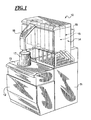
- FIG. 1 is perspective view of a fluid dispensing apparatus that can utilize the improved canisters disclosed herein;
- FIG. 2 is perspective view of another fluid dispensing apparatus that can utilize the improved canisters disclosed herein;
- FIG. 3A is a perspective view of a disclosed fluid canister, agitation motor and fluid pump
- FIG. 3B is a front plan view of the disclosed fluid canister, agitation motor and fluid pump of FIG. 3A ;
- FIG. 3C is a front plan view of the disclosed fluid canister, agitation motor and fluid pump of FIGS. 3A and 3B with the outer canister shell removed;
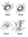
- FIGS. 4A and 4B are perspective views of an improved screen design for use in the canister of FIG. 3 ;
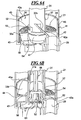
- FIGS. 5A is a perspective view of a bottom scraping blade that snap-fits onto a lower end of the agitation blade partially shown in FIG. 5B ;
- FIG. 5B is a partial perspective view of a disclosed agitation blade
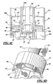
- FIG. 6A is a partial sectional view illustrating the relationship between the screen of FIGS. 4A-4B , the bottom scraping blade of FIG. 5A and the agitation blade of FIG. 5B ;
- FIG. 6B is another partial sectional view illustrating the relationship between the screen of FIGS. 4A-4B , the bottom scraping blade of FIG. 5A and the agitation blade of FIG. 5B ;
- FIGS. 1 and 2 disclose dispensing apparatuses that can utilize the improved canister designs disclosed herein.
- FIG. 1 discloses a dispensing apparatus 10 which includes a rear base portion/housing 11 connected to a lower front cabinet 12 which, in turn, is disposed beneath and supports an upper front cabinet shown at 13.
- the upper front cabinet 13 may also include a scale or weighing function (not shown). Any one of the cabinets 11 through 13 may house a controller and other electronic equipment (not shown).
- the cabinet 11 supports an upper rear cabinet 14 which, in turn, houses a plurality of modules which are represented by pairs of canisters shown generally at 15. It is the improved design of the canisters 15 which are the primary subject of this disclosure.
- FIG. 1 discloses a dispensing apparatus 10 which includes a rear base portion/housing 11 connected to a lower front cabinet 12 which, in turn, is disposed beneath and supports an upper front cabinet shown at 13.
- the upper front cabinet 13 may also include a scale or weighing function (not shown). Any one of the cabinets 11
- FIG. 1 also illustrates a manifold module 16 through which fluid is simultaneously or sequentially dispensed into the container 17 from the fluid canisters 15.
- FIG. 2 discloses a cabinet 11a which supports a plurality of canisters (not shown) in the canister bracket 15a.
- a cabinet 12a and removable support structure 13a supports the container 17a below the manifold 16a.
- the canister 15 includes a cylindrical shell 21 with an open top covered by a lid 22.
- the lid 22 includes a tab 23 to facilitate removal thereof.
- Below the shell 21 is a pair of brackets 24 that connect the canister 15 to a fluid pump 25.
- the pump motor is shown at 26.
- An agitation motor 27 is used to turn the agitator 28 shown in FIG. 3C .
- the agitator 28 comprises a shaft 31 with a plurality of radially outwardly extending blades 32 axially spaced along the shaft 31.
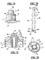
- An upper end 33 of the shaft 31 includes a ring 34 that supports the centralizer 35 that will be discussed in greater detail below in connection with FIG. 7D .
- the upper end 33 of the shaft 31 is also connected to a deflector cap 36 that will be discussed in greater detail below in connection with FIGS. 7A and 7C .
- the lower end 37 of the shaft 31 passes through a screen 38 and will be discussed in greater detail below in connection with FIGS. 4A-4B and 6A-6D .
- the connection between the shaft 31 and the agitation motor 27 is illustrated in FIGS. 6B-6C .
- an improved screen/filter 38 is disclosed.
- the screen 38 serves as a filter to remix settled solids and sediment back into the fluid before the fluid passes down through the outlet 29 to the pump 25.
- screen filters known in the art have a tendency to clog.
- the proximity of prior art screen filters to the bottom outlet line 29 can limit the effective surface area of the screen to the portion of the screen disposed immediately above the outlet.
- the screen 38 is disposed within a vertical cylindrical housing 41 that includes a lower portion 42 disposed below the screen along with supporting legs 43 that effectively elevate the filter element 44 above the outlet 29 as illustrated below in connection with FIGS. 6A-6D .
- the upper portion 45 of the housing 41 fits snugly within the canister shell 21.
- the lower portion 42 of the cylindrical housing 41 terminates at a lower end 42a and the upper portion 45 of the cylindrical housing 41 terminates at an upper end 45a.
- the screen 38 is attached to the lower end 37 of the shaft 31 by the snap-fit connection between the lower blade element 46 and the lower end 37 of the shaft 31.
- the lower blade element 46 includes a lower cylinder 47 with a recessed upper portion 48 that fits within the lower rim 49 of the lower end of 37 of the shaft 31.
- a pair of upwardly protruding legs 51 also fit within the lower rim 49 of the shaft 31.
- the legs 51 are equipped with radially outwardly protruding tabs 52 that snap-fit into openings, only one of which is shown at 53 in FIG. 5B .
- the screen element 44 is sandwiched between the upward facing ledge 54 ( FIG. 5A ) and the lower rim 49 ( FIG. 5B ).
- the lower blades 32a and upper blades 32b scrape the bottom and top of the screen element 44 respectively.
- FIGS. 6A-6C The assembly of the lower blade element 46 onto the lower end 37 of the shaft 31 with the screen element 38 sandwiched therebetween is further illustrated in the sectional views of FIGS. 6A-6C .
- the product outlet is shown at 29 which is spaced sufficiently below the screen element 44 so as to permit passage of the lower blades 32a therebetween.
- a bracket 56 is also shown which supports the agitation motor 27 in which is connected to the vertical brackets 24 as shown in FIGS. 3A-3C .
- the agitation motor shaft is shown at 57 in FIG. 6B .
- the outer shell 21 also forms an inner standpipe 21 a which fits inside of the shaft 31.
- a bottom panel 21 b connects the inner standpipe 21 a to the outer cylindrical shell 21 thereby providing the canister 15 with an annular housing that is unitary in structure with the exception of the open top 21d (see FIG. 7C ) and the outlet opening 29 ( FIGS. 6A-6C ) that is formed in the bottom panel 21b.
- a coupling shaft 58 is disposed within the standpipe 21 a that couples the motor shaft 57 to the agitator shaft 31. More specifically, as illustrated in FIG. 7C . the agitator motor shaft 57 is connected to a crossbar 61 which, in turn, is coupled to the lower fork 62 of the coupling shaft 58. As the coupling shaft 58 is connected to the upper and 33 of the agitator shaft 31, the agitator motor shaft 57 can indirectly impart rotation to the agitator blades 32.
- FIGS. 7A-7D illustrate the upper and 33 of the agitator shaft 31 in greater detail.
- the upper end 33 of the shaft 31 includes the ring 34 which serves as a seat for the centralizer 35.
- the upper end 33 of the shaft 31 also includes a pair of opposing cleats 66 which snap-fit into the openings 67 (only one of which is shown in FIG. 7A ).
- the deflector cap 36 includes a lower flange that rests on the centralizer 35 (see FIG. 7C ), a closed top 68 and solid sidewall structures 69, 71 with the exception of the openings 67 for the cleats 66.
- the lower sidewall 71 is connected to the upper side wall 69 by the horizontal step 70 (see FIG. 7C ).
- the lower sidewall 71 is connected to the lower flange 65.
- the lower flange 65 has a diameter greater than the lower cylindrical wall 71 which has a greater diameter than the upper cylindrical wall 69.
- opposing channels 72 are provided for accommodating the cleats 66 of the agitator shaft 31.
- the snap-fit of the deflector cap 36 onto the upper end 33 of the shaft 31 prevents any fluid from flowing downward through the hollow shaft 31 towards the motor shaft (see FIGS. 6B-6C ).
- FIG. 7D discloses the centralizer 35 which fits over the upper end 33 of the shaft and rests on the ring or circumferential rib 34 as shown in FIG. 7C .
- the centralizer 35 serves as a seat for the lower flange 65 of the deflector cap 36.
- the centralizer 35 includes an outer ring 73 connected to an inner ring 74 by a plurality of spokes 75.
- the inner ring 74 includes opposing recesses 76 that slide past the cleats 66 disposed on the upper end 33 of the shaft 31 ( FIG. 7B ).
- the inner ring 74 also includes a flange 77 that supports the lower flange 65 of the deflector cap 36 as seen in FIG. 7C .
- the centralizer holds the agitator 28 in place and helps to prevent spillage.
- the deflector cap 36 prevents spillage of material down through the shaft 31 of the agitator 28.
Landscapes
- Chemical & Material Sciences (AREA)
- Chemical Kinetics & Catalysis (AREA)
- Mixers Of The Rotary Stirring Type (AREA)
- Containers And Packaging Bodies Having A Special Means To Remove Contents (AREA)
- Filling Or Discharging Of Gas Storage Vessels (AREA)
Claims (13)
- Ensemble de bidon (15) pour stocker des fluides visqueux, l'ensemble de bidon comprenant :un logement annulaire (21) comprenant une paroi cylindrique extérieure, un fond et un tuyau de montée intérieur, le fond comprenant une sortie (29), le fond reliant la paroi cylindrique extérieure au tuyau de montée intérieur,un élément formant tamis annulaire (38) qui coulisse sur le tuyau de montée, l'élément formant tamis annulaire comprenant une coque extérieure cylindrique (45) qui coulisse à l'intérieur de la paroi cylindrique extérieure de la coque annulaire, la coque extérieure cylindrique verticale ayant une extrémité supérieure et une extrémité inférieure, l'élément formant tamis annulaire comprenant en outre un tamis annulaire disposé horizontalement dans la coque extérieure cylindrique verticale et distante au-dessus de son extrémité inférieure, l'extrémité inférieure de la coque extérieure cylindrique verticale supportant l'élément formant tamis au-dessus du fond du logement annulaire et de la sortie.
- Ensemble de bidon selon la revendication 1, dans lequel l'élément formant tamis annulaire (38) est fabriqué à partir de plastique moulé.
- Ensemble de bidon selon la revendication 1, dans lequel l'extrémité inférieure de la coque extérieure cylindrique verticale (45) de l'élément formant tamis annulaire (38) est reliée à un pied s'étendant vers le bas (43) qui supporte l'extrémité inférieure de la coque extérieure cylindrique verticale et le tamis annulaire au-dessus du fond du logement annulaire et au-dessus de la sortie dans le fond du logement annulaire.
- Ensemble de bidon selon la revendication 1, comprenant en outre un arbre creux d'agitateur qui coulisse sur le tuyau de montée au-dessus de l'élément formant tamis annulaire, le bidon comprenant en outre un élément formant lame inférieure (46) qui coulisse sur le tuyau de montée et est positionné au-dessous de l'élément formant tamis annulaire, l'élément formant lame inférieure et l'arbre d'agitateur étant reliés ensemble, l'élément formant tamis annulaire étant pris en sandwich entre les deux.
- Ensemble de bidon selon la revendication 4, dans lequel l'élément formant lame inférieure (46) comprend au moins une lame s'étendant radialement (32a) qui s'accouple avec un côté inférieur du tamis annulaire (44) et l'arbre d'agitateur comprend ladite au moins une lame s'étendant radialement (32a) qui s'accouple avec une surface supérieure du tamis annulaire (44).
- Ensemble de bidon selon la revendication 4 ou 5, dans lequel l'élément formant lame inférieure (46) et l'arbre d'agitateur (31) sont emboîtés ensemble par pression.
- Ensemble de bidon selon la revendication 1, dans lequel une extrémité supérieure de l'arbre creux d'agitateur est reliée à un bouchon déverseur (36) pour enfermer l'extrémité supérieure de l'arbre creux d'agitateur (31).
- Ensemble de bidon selon la revendication 7, dans lequel le bouchon déverseur (36) comprend
un rebord inférieur relié à une paroi cylindrique inférieure et disposé en dessous de celle-ci, le rebord inférieur ayant un diamètre extérieur maximal supérieur à celui de la paroi cylindrique inférieure,
la paroi cylindrique inférieure reliée à une paroi cylindrique supérieure par un palier horizontal, la paroi cylindrique supérieure reliée à un espace clos par un dessus plein (68), le diamètre extérieur maximal de la paroi cylindrique inférieure étant supérieur à celui de la paroi cylindrique supérieure,
la paroi cylindrique inférieure comprenant des ouvertures diamétralement opposées (72) et une paire d'évidements verticaux diamétralement opposés s'étendant depuis le rebord inférieur vers l'une des ouvertures,
l'arbre creux d'agitateur comprenant une paire de taquets diamétralement opposés (66) qui s'emboîtent par pression dans les ouvertures de la paroi cylindrique inférieure du bouchon déverseur. - Ensemble de bidon selon la revendication 4, comprenant en outre un centreur (35) s'adaptant sur l'arbre creux d'agitateur (31), le centreur comprenant une bague extérieure reliée à une bague intérieure par une pluralité de rayons s'étendant radialement, l'arbre d'agitateur comprenant une nervure périphérique, la bague intérieure du centreur comprenant un rebord inférieur horizontal qui s'accouple avec le rebord supporté par la nervure périphérique.
- Ensemble de bidon selon la revendication 8, comprenant en outre un centreur (35) s'adaptant sur l'arbre creux d'agitateur (31), le centreur comprenant une bague extérieure reliée à une bague intérieure par une pluralité de rayons s'étendant radialement, la bague intérieure du centreur comprenant une paire d'évidements diamétralement opposés destinés à recevoir les taquets de l'arbre d'agitateur et permettant au centreur de coulisser vers le bas sur l'arbre au-delà des taquets (66), l'arbre d'agitateur (31) comprenant une nervure périphérique, la bague intérieure du centreur comprenant un rebord inférieur horizontal qui s'accouple avec le rebord supporté par la nervure périphérique.
- Ensemble de bidon selon l'une quelconque des revendications 1 à 10, comprenant en outre
un arbre creux d'agitateur (31) s'adaptant sur le tuyau de montée et au-dessus de l'élément formant tamis annulaire (44),
un élément formant lame inférieure (46) s'adaptant sur le tuyau de montée et au-dessous de l'élément formant tamis annulaire, l'élément formant lame inférieure et l'arbre d'agitateur étant reliés ensemble, l'élément formant tamis annulaire étant pris en sandwich entre les deux. - Ensemble de bidon selon la revendication 1, dans lequel le fond comprend une sortie (29) raccordée à une pompe.
- Ensemble de bidon selon la revendication 1, comprenant un arbre creux d'agitateur (31) s'adaptant sur le tuyau de montée et au-dessus de l'élément formant tamis annulaire (44),
une extrémité supérieure de l'arbre creux d'agitateur (31) étant emboîtée par pression sur un bouchon déverseur (36) pour enfermer l'extrémité supérieure de l'arbre creux d'agitateur, et
le bouchon déverseur (36) comprenant un rebord inférieur relié à un dessus plein et disposé en dessous de celui-ci.
Applications Claiming Priority (2)
| Application Number | Priority Date | Filing Date | Title |
|---|---|---|---|
| US11/686,273 US7959348B2 (en) | 2007-03-14 | 2007-03-14 | Agitating canister for viscous fluids dispensed from multiple fluid dispensers |
| PCT/EP2008/053020 WO2008110606A1 (fr) | 2007-03-14 | 2008-03-13 | Bidon à agitation destiné à des fluides visqueux pour un distributeur de fluide multiple |
Publications (2)
| Publication Number | Publication Date |
|---|---|
| EP2139593A1 EP2139593A1 (fr) | 2010-01-06 |
| EP2139593B1 true EP2139593B1 (fr) | 2011-09-07 |
Family
ID=39445445
Family Applications (1)
| Application Number | Title | Priority Date | Filing Date |
|---|---|---|---|
| EP08717764A Not-in-force EP2139593B1 (fr) | 2007-03-14 | 2008-03-13 | Ensemble de cartouche pour le stockage de fluides visqueux |
Country Status (8)
| Country | Link |
|---|---|
| US (1) | US7959348B2 (fr) |
| EP (1) | EP2139593B1 (fr) |
| CN (1) | CN101678290B (fr) |
| AT (1) | ATE523243T1 (fr) |
| AU (1) | AU2008225761A1 (fr) |
| BR (1) | BRPI0808756A8 (fr) |
| CA (1) | CA2680452A1 (fr) |
| WO (1) | WO2008110606A1 (fr) |
Families Citing this family (17)
| Publication number | Priority date | Publication date | Assignee | Title |
|---|---|---|---|---|
| US7959348B2 (en) * | 2007-03-14 | 2011-06-14 | Fluid Management, Inc. | Agitating canister for viscous fluids dispensed from multiple fluid dispensers |
| US8960994B2 (en) * | 2010-03-22 | 2015-02-24 | Eric D. Schwartz | Portable custom nail polish creator |
| US10549247B2 (en) | 2010-03-22 | 2020-02-04 | Eric D. Schwartz | Portable custom nail polish creator |
| US9724658B2 (en) | 2011-03-28 | 2017-08-08 | Fast & Fluid Management B.V. | Method of homogenizing a liquid |
| ITRE20110028A1 (it) * | 2011-04-20 | 2012-10-21 | Ufi Innovation Ct Srl | Gruppo filtrante |
| EP2771632A2 (fr) * | 2011-10-27 | 2014-09-03 | Arçelik Anonim Sirketi | Dispositif de refroidissement comprenant un réservoir de stockage dans lequel le liquide qui s'y trouve est stérilisé |
| US8960999B1 (en) | 2014-03-28 | 2015-02-24 | Gudpod Holdings, Llc | System for mixing beverages and method of doing the same |
| KR20180009734A (ko) * | 2015-01-15 | 2018-01-29 | 크롭 에스.피.에이. 콘 소시오 유니코 | 유체 제품을 위한 교반 장치를 갖는 컨테이너 |
| CN105498585A (zh) * | 2016-01-07 | 2016-04-20 | 永胜机械工业(昆山)有限公司 | 一种预混槽搅拌装置 |
| DE102016123712A1 (de) * | 2016-12-07 | 2018-06-07 | Maschinenfabrik Gustav Eirich Gmbh & Co. Kg | Mischflügel mit Verschleißelement sowie Verfahren zum Befestigen eines Verschleißelementes an einem Grundteil eines Mischflügels |
| EP3332865B1 (fr) | 2016-12-11 | 2021-02-03 | Fast&Fluid Management B.V. | Agitateur pour un liquide visqueux |
| US20190299524A1 (en) * | 2018-03-28 | 2019-10-03 | 3D Systems, Inc. | Three dimensional printing system adaptable to varying resin types |
| IT201800010766A1 (it) * | 2018-12-03 | 2020-06-03 | Dromont S P A | Macchina dosatrice per prodotti fluidi quali coloranti per vernici o simili |
| US11877529B2 (en) | 2019-02-01 | 2024-01-23 | Cnh Industrial Canada, Ltd. | Deflector of an agricultural agitation system |
| US11484853B2 (en) | 2019-02-01 | 2022-11-01 | Cnh Industrial Canada, Ltd. | Deflector of an agricultural agitation system |
| CN110314587B (zh) * | 2019-07-31 | 2021-07-09 | 山东腾飞机电科技有限公司 | 一种建筑涂料小型搅拌设备 |
| CN110860222A (zh) * | 2019-12-19 | 2020-03-06 | 上海弗鲁克科技发展有限公司 | 强化高黏度流体混合装置 |
Family Cites Families (15)
| Publication number | Priority date | Publication date | Assignee | Title |
|---|---|---|---|---|
| US1969006A (en) * | 1930-10-10 | 1934-08-07 | William P Herman | Fruit juice extractor |
| US2247948A (en) * | 1939-06-05 | 1941-07-01 | Herbert C Johnson | Juice extracting device |
| US2533811A (en) * | 1946-02-01 | 1950-12-12 | Sunbeam Corp | Juice extracting device with vibrating strainer |
| US2566555A (en) * | 1947-11-21 | 1951-09-04 | Maple Island Inc | Apparatus for reconstituting dried powders |
| US3559962A (en) * | 1968-06-10 | 1971-02-02 | Binks Res & Dev | Stirring device |
| NZ191138A (en) * | 1978-08-25 | 1981-01-23 | Breville Holdings Pty Ltd | Citrus juicer attachment for food processor |
| FR2459031A1 (fr) * | 1979-06-18 | 1981-01-09 | Robot Coupe Sa | Dispositif presse-agrumes pour robot de cuisine |
| DE59003001D1 (de) * | 1989-09-16 | 1993-11-11 | Braun Ag | Elektrisch angetriebene Zitruspresse. |
| GB2299522B (en) | 1995-04-03 | 1998-09-16 | Barrufet Maria Elena Rodriguez | A mixer |
| US6273298B1 (en) * | 2000-03-08 | 2001-08-14 | Fluid Management, Inc. | Apparatus for dispensing viscous fluids from flexible packages and holder for such packages |
| FR2861563B1 (fr) * | 2003-11-04 | 2005-12-30 | Seb Sa | Appareil presse agrumes avec accessoire de deversement |
| DE102004055072A1 (de) * | 2004-11-15 | 2006-05-18 | Reichmann-Schurr, geb. Wenzler, Margot | Vorrichtung zur Zumischung eines Polymers in eine Flüssigkeit |
| US7562680B2 (en) * | 2005-07-15 | 2009-07-21 | Fluid Management Operations, Llc | Multiple fluid dispenser |
| US7690405B2 (en) | 2005-07-18 | 2010-04-06 | Fluid Management, Inc. | Multiple fluid dispenser |
| US7959348B2 (en) * | 2007-03-14 | 2011-06-14 | Fluid Management, Inc. | Agitating canister for viscous fluids dispensed from multiple fluid dispensers |
-
2007
- 2007-03-14 US US11/686,273 patent/US7959348B2/en active Active
-
2008
- 2008-03-13 AU AU2008225761A patent/AU2008225761A1/en not_active Abandoned
- 2008-03-13 AT AT08717764T patent/ATE523243T1/de not_active IP Right Cessation
- 2008-03-13 EP EP08717764A patent/EP2139593B1/fr not_active Not-in-force
- 2008-03-13 CN CN2008800129335A patent/CN101678290B/zh active Active
- 2008-03-13 CA CA002680452A patent/CA2680452A1/fr not_active Abandoned
- 2008-03-13 WO PCT/EP2008/053020 patent/WO2008110606A1/fr not_active Ceased
- 2008-03-13 BR BRPI0808756A patent/BRPI0808756A8/pt not_active IP Right Cessation
Also Published As
| Publication number | Publication date |
|---|---|
| BRPI0808756A2 (pt) | 2014-08-12 |
| WO2008110606A1 (fr) | 2008-09-18 |
| US7959348B2 (en) | 2011-06-14 |
| AU2008225761A1 (en) | 2008-09-18 |
| BRPI0808756A8 (pt) | 2018-12-18 |
| ATE523243T1 (de) | 2011-09-15 |
| CA2680452A1 (fr) | 2008-09-18 |
| US20080225637A1 (en) | 2008-09-18 |
| CN101678290B (zh) | 2013-05-22 |
| CN101678290A (zh) | 2010-03-24 |
| EP2139593A1 (fr) | 2010-01-06 |
Similar Documents
| Publication | Publication Date | Title |
|---|---|---|
| EP2139593B1 (fr) | Ensemble de cartouche pour le stockage de fluides visqueux | |
| CA2507306C (fr) | Appareil de distribution d'echantillons de peinture et de teinture, et methodes de distribution de ces echantillons | |
| CN1925905B (zh) | 颜料和染发剂分配机 | |
| US9724658B2 (en) | Method of homogenizing a liquid | |
| US5533802A (en) | Paint can accessory | |
| US8807821B2 (en) | Device for mixing a compound in a container | |
| US8413847B2 (en) | Rotary nozzle recirculation systems | |
| EP3332865B1 (fr) | Agitateur pour un liquide visqueux | |
| US12528311B2 (en) | Paint mixing container | |
| JP2999471B1 (ja) | 具入りス―プ類の小分け装置 | |
| US8496032B2 (en) | Manually operable manifold/nozzle closure for fluid dispensers | |
| US7261131B2 (en) | Articulated nozzle closure for fluid dispensers | |
| US4241744A (en) | Cleaning system for tanks | |
| EP1352874B1 (fr) | Dispositif pour délivrer de la peinture | |
| CN100475323C (zh) | 盛放液体产品的容器 | |
| US7581571B2 (en) | Manually operable manifold/nozzle closure for fluid dispenser | |
| JP2022549357A (ja) | 化学容器撹拌機 | |
| US8141600B2 (en) | Fluid dispenser with improved shelving system for accommodating containers of various sizes | |
| JP7458179B2 (ja) | 化粧品容器 | |
| CN224023431U (zh) | 双头皂液器 | |
| JPH0516873U (ja) | 水洗タンクの薬剤容器 | |
| GB2417676A (en) | Bottle drainage rack |
Legal Events
| Date | Code | Title | Description |
|---|---|---|---|
| PUAI | Public reference made under article 153(3) epc to a published international application that has entered the european phase |
Free format text: ORIGINAL CODE: 0009012 |
|
| 17P | Request for examination filed |
Effective date: 20091014 |
|
| AK | Designated contracting states |
Kind code of ref document: A1 Designated state(s): AT BE BG CH CY CZ DE DK EE ES FI FR GB GR HR HU IE IS IT LI LT LU LV MC MT NL NO PL PT RO SE SI SK TR |
|
| 17Q | First examination report despatched |
Effective date: 20100209 |
|
| RIN1 | Information on inventor provided before grant (corrected) |
Inventor name: HOGAN, TIM PATRICK |
|
| DAX | Request for extension of the european patent (deleted) | ||
| RTI1 | Title (correction) |
Free format text: CANISTER ASSEMBLY FOR STORING VISCOUS FLUIDS |
|
| GRAP | Despatch of communication of intention to grant a patent |
Free format text: ORIGINAL CODE: EPIDOSNIGR1 |
|
| GRAS | Grant fee paid |
Free format text: ORIGINAL CODE: EPIDOSNIGR3 |
|
| GRAA | (expected) grant |
Free format text: ORIGINAL CODE: 0009210 |
|
| REG | Reference to a national code |
Ref country code: GB Ref legal event code: FG4D |
|
| REG | Reference to a national code |
Ref country code: CH Ref legal event code: EP |
|
| REG | Reference to a national code |
Ref country code: IE Ref legal event code: FG4D |
|
| REG | Reference to a national code |
Ref country code: DE Ref legal event code: R096 Ref document number: 602008009560 Country of ref document: DE Effective date: 20111103 |
|
| REG | Reference to a national code |
Ref country code: NL Ref legal event code: VDEP Effective date: 20110907 |
|
| PG25 | Lapsed in a contracting state [announced via postgrant information from national office to epo] |
Ref country code: SE Free format text: LAPSE BECAUSE OF FAILURE TO SUBMIT A TRANSLATION OF THE DESCRIPTION OR TO PAY THE FEE WITHIN THE PRESCRIBED TIME-LIMIT Effective date: 20110907 Ref country code: LT Free format text: LAPSE BECAUSE OF FAILURE TO SUBMIT A TRANSLATION OF THE DESCRIPTION OR TO PAY THE FEE WITHIN THE PRESCRIBED TIME-LIMIT Effective date: 20110907 Ref country code: NO Free format text: LAPSE BECAUSE OF FAILURE TO SUBMIT A TRANSLATION OF THE DESCRIPTION OR TO PAY THE FEE WITHIN THE PRESCRIBED TIME-LIMIT Effective date: 20111207 Ref country code: FI Free format text: LAPSE BECAUSE OF FAILURE TO SUBMIT A TRANSLATION OF THE DESCRIPTION OR TO PAY THE FEE WITHIN THE PRESCRIBED TIME-LIMIT Effective date: 20110907 Ref country code: HR Free format text: LAPSE BECAUSE OF FAILURE TO SUBMIT A TRANSLATION OF THE DESCRIPTION OR TO PAY THE FEE WITHIN THE PRESCRIBED TIME-LIMIT Effective date: 20110907 |
|
| LTIE | Lt: invalidation of european patent or patent extension |
Effective date: 20110907 |
|
| PG25 | Lapsed in a contracting state [announced via postgrant information from national office to epo] |
Ref country code: GR Free format text: LAPSE BECAUSE OF FAILURE TO SUBMIT A TRANSLATION OF THE DESCRIPTION OR TO PAY THE FEE WITHIN THE PRESCRIBED TIME-LIMIT Effective date: 20111208 Ref country code: AT Free format text: LAPSE BECAUSE OF FAILURE TO SUBMIT A TRANSLATION OF THE DESCRIPTION OR TO PAY THE FEE WITHIN THE PRESCRIBED TIME-LIMIT Effective date: 20110907 Ref country code: CY Free format text: LAPSE BECAUSE OF FAILURE TO SUBMIT A TRANSLATION OF THE DESCRIPTION OR TO PAY THE FEE WITHIN THE PRESCRIBED TIME-LIMIT Effective date: 20110907 Ref country code: LV Free format text: LAPSE BECAUSE OF FAILURE TO SUBMIT A TRANSLATION OF THE DESCRIPTION OR TO PAY THE FEE WITHIN THE PRESCRIBED TIME-LIMIT Effective date: 20110907 Ref country code: SI Free format text: LAPSE BECAUSE OF FAILURE TO SUBMIT A TRANSLATION OF THE DESCRIPTION OR TO PAY THE FEE WITHIN THE PRESCRIBED TIME-LIMIT Effective date: 20110907 |
|
| REG | Reference to a national code |
Ref country code: AT Ref legal event code: MK05 Ref document number: 523243 Country of ref document: AT Kind code of ref document: T Effective date: 20110907 |
|
| PG25 | Lapsed in a contracting state [announced via postgrant information from national office to epo] |
Ref country code: BE Free format text: LAPSE BECAUSE OF FAILURE TO SUBMIT A TRANSLATION OF THE DESCRIPTION OR TO PAY THE FEE WITHIN THE PRESCRIBED TIME-LIMIT Effective date: 20110907 |
|
| PG25 | Lapsed in a contracting state [announced via postgrant information from national office to epo] |
Ref country code: CZ Free format text: LAPSE BECAUSE OF FAILURE TO SUBMIT A TRANSLATION OF THE DESCRIPTION OR TO PAY THE FEE WITHIN THE PRESCRIBED TIME-LIMIT Effective date: 20110907 Ref country code: IS Free format text: LAPSE BECAUSE OF FAILURE TO SUBMIT A TRANSLATION OF THE DESCRIPTION OR TO PAY THE FEE WITHIN THE PRESCRIBED TIME-LIMIT Effective date: 20120107 Ref country code: SK Free format text: LAPSE BECAUSE OF FAILURE TO SUBMIT A TRANSLATION OF THE DESCRIPTION OR TO PAY THE FEE WITHIN THE PRESCRIBED TIME-LIMIT Effective date: 20110907 |
|
| PG25 | Lapsed in a contracting state [announced via postgrant information from national office to epo] |
Ref country code: NL Free format text: LAPSE BECAUSE OF FAILURE TO SUBMIT A TRANSLATION OF THE DESCRIPTION OR TO PAY THE FEE WITHIN THE PRESCRIBED TIME-LIMIT Effective date: 20110907 Ref country code: IT Free format text: LAPSE BECAUSE OF FAILURE TO SUBMIT A TRANSLATION OF THE DESCRIPTION OR TO PAY THE FEE WITHIN THE PRESCRIBED TIME-LIMIT Effective date: 20110907 Ref country code: EE Free format text: LAPSE BECAUSE OF FAILURE TO SUBMIT A TRANSLATION OF THE DESCRIPTION OR TO PAY THE FEE WITHIN THE PRESCRIBED TIME-LIMIT Effective date: 20110907 Ref country code: PT Free format text: LAPSE BECAUSE OF FAILURE TO SUBMIT A TRANSLATION OF THE DESCRIPTION OR TO PAY THE FEE WITHIN THE PRESCRIBED TIME-LIMIT Effective date: 20120109 Ref country code: RO Free format text: LAPSE BECAUSE OF FAILURE TO SUBMIT A TRANSLATION OF THE DESCRIPTION OR TO PAY THE FEE WITHIN THE PRESCRIBED TIME-LIMIT Effective date: 20110907 Ref country code: PL Free format text: LAPSE BECAUSE OF FAILURE TO SUBMIT A TRANSLATION OF THE DESCRIPTION OR TO PAY THE FEE WITHIN THE PRESCRIBED TIME-LIMIT Effective date: 20110907 |
|
| PLBE | No opposition filed within time limit |
Free format text: ORIGINAL CODE: 0009261 |
|
| STAA | Information on the status of an ep patent application or granted ep patent |
Free format text: STATUS: NO OPPOSITION FILED WITHIN TIME LIMIT |
|
| PG25 | Lapsed in a contracting state [announced via postgrant information from national office to epo] |
Ref country code: DK Free format text: LAPSE BECAUSE OF FAILURE TO SUBMIT A TRANSLATION OF THE DESCRIPTION OR TO PAY THE FEE WITHIN THE PRESCRIBED TIME-LIMIT Effective date: 20110907 |
|
| 26N | No opposition filed |
Effective date: 20120611 |
|
| REG | Reference to a national code |
Ref country code: DE Ref legal event code: R097 Ref document number: 602008009560 Country of ref document: DE Effective date: 20120611 |
|
| PG25 | Lapsed in a contracting state [announced via postgrant information from national office to epo] |
Ref country code: MC Free format text: LAPSE BECAUSE OF NON-PAYMENT OF DUE FEES Effective date: 20120331 |
|
| REG | Reference to a national code |
Ref country code: CH Ref legal event code: PL |
|
| GBPC | Gb: european patent ceased through non-payment of renewal fee |
Effective date: 20120313 |
|
| REG | Reference to a national code |
Ref country code: FR Ref legal event code: ST Effective date: 20121130 |
|
| REG | Reference to a national code |
Ref country code: IE Ref legal event code: MM4A |
|
| PG25 | Lapsed in a contracting state [announced via postgrant information from national office to epo] |
Ref country code: LI Free format text: LAPSE BECAUSE OF NON-PAYMENT OF DUE FEES Effective date: 20120331 Ref country code: FR Free format text: LAPSE BECAUSE OF NON-PAYMENT OF DUE FEES Effective date: 20120402 Ref country code: CH Free format text: LAPSE BECAUSE OF NON-PAYMENT OF DUE FEES Effective date: 20120331 Ref country code: GB Free format text: LAPSE BECAUSE OF NON-PAYMENT OF DUE FEES Effective date: 20120313 Ref country code: IE Free format text: LAPSE BECAUSE OF NON-PAYMENT OF DUE FEES Effective date: 20120313 |
|
| REG | Reference to a national code |
Ref country code: DE Ref legal event code: R119 Ref document number: 602008009560 Country of ref document: DE Effective date: 20121002 |
|
| PG25 | Lapsed in a contracting state [announced via postgrant information from national office to epo] |
Ref country code: ES Free format text: LAPSE BECAUSE OF FAILURE TO SUBMIT A TRANSLATION OF THE DESCRIPTION OR TO PAY THE FEE WITHIN THE PRESCRIBED TIME-LIMIT Effective date: 20111218 |
|
| PG25 | Lapsed in a contracting state [announced via postgrant information from national office to epo] |
Ref country code: BG Free format text: LAPSE BECAUSE OF FAILURE TO SUBMIT A TRANSLATION OF THE DESCRIPTION OR TO PAY THE FEE WITHIN THE PRESCRIBED TIME-LIMIT Effective date: 20111207 |
|
| PG25 | Lapsed in a contracting state [announced via postgrant information from national office to epo] |
Ref country code: MT Free format text: LAPSE BECAUSE OF FAILURE TO SUBMIT A TRANSLATION OF THE DESCRIPTION OR TO PAY THE FEE WITHIN THE PRESCRIBED TIME-LIMIT Effective date: 20110907 |
|
| PG25 | Lapsed in a contracting state [announced via postgrant information from national office to epo] |
Ref country code: TR Free format text: LAPSE BECAUSE OF FAILURE TO SUBMIT A TRANSLATION OF THE DESCRIPTION OR TO PAY THE FEE WITHIN THE PRESCRIBED TIME-LIMIT Effective date: 20110907 |
|
| PG25 | Lapsed in a contracting state [announced via postgrant information from national office to epo] |
Ref country code: LU Free format text: LAPSE BECAUSE OF NON-PAYMENT OF DUE FEES Effective date: 20120313 |
|
| PG25 | Lapsed in a contracting state [announced via postgrant information from national office to epo] |
Ref country code: HU Free format text: LAPSE BECAUSE OF FAILURE TO SUBMIT A TRANSLATION OF THE DESCRIPTION OR TO PAY THE FEE WITHIN THE PRESCRIBED TIME-LIMIT Effective date: 20080313 |
|
| PG25 | Lapsed in a contracting state [announced via postgrant information from national office to epo] |
Ref country code: DE Free format text: LAPSE BECAUSE OF FAILURE TO SUBMIT A TRANSLATION OF THE DESCRIPTION OR TO PAY THE FEE WITHIN THE PRESCRIBED TIME-LIMIT Effective date: 20121002 |