EP2139104B1 - Inverseur photovoltaïque haute efficacité avec un convertisseur abaisseur - Google Patents
Inverseur photovoltaïque haute efficacité avec un convertisseur abaisseur Download PDFInfo
- Publication number
- EP2139104B1 EP2139104B1 EP09163101.0A EP09163101A EP2139104B1 EP 2139104 B1 EP2139104 B1 EP 2139104B1 EP 09163101 A EP09163101 A EP 09163101A EP 2139104 B1 EP2139104 B1 EP 2139104B1
- Authority
- EP
- European Patent Office
- Prior art keywords
- inverter
- voltage
- current
- array
- converter
- Prior art date
- Legal status (The legal status is an assumption and is not a legal conclusion. Google has not performed a legal analysis and makes no representation as to the accuracy of the status listed.)
- Active
Links
Images


Classifications
-
- H—ELECTRICITY
- H02—GENERATION; CONVERSION OR DISTRIBUTION OF ELECTRIC POWER
- H02M—APPARATUS FOR CONVERSION BETWEEN AC AND AC, BETWEEN AC AND DC, OR BETWEEN DC AND DC, AND FOR USE WITH MAINS OR SIMILAR POWER SUPPLY SYSTEMS; CONVERSION OF DC OR AC INPUT POWER INTO SURGE OUTPUT POWER; CONTROL OR REGULATION THEREOF
- H02M7/00—Conversion of AC power input into DC power output; Conversion of DC power input into AC power output
- H02M7/42—Conversion of DC power input into AC power output without possibility of reversal
- H02M7/44—Conversion of DC power input into AC power output without possibility of reversal by static converters
- H02M7/48—Conversion of DC power input into AC power output without possibility of reversal by static converters using discharge tubes with control electrode or semiconductor devices with control electrode
- H02M7/53—Conversion of DC power input into AC power output without possibility of reversal by static converters using discharge tubes with control electrode or semiconductor devices with control electrode using devices of a triode or transistor type requiring continuous application of a control signal
- H02M7/537—Conversion of DC power input into AC power output without possibility of reversal by static converters using discharge tubes with control electrode or semiconductor devices with control electrode using devices of a triode or transistor type requiring continuous application of a control signal using semiconductor devices only, e.g. single switched pulse inverters
- H02M7/5387—Conversion of DC power input into AC power output without possibility of reversal by static converters using discharge tubes with control electrode or semiconductor devices with control electrode using devices of a triode or transistor type requiring continuous application of a control signal using semiconductor devices only, e.g. single switched pulse inverters in a bridge configuration
- H02M7/53871—Conversion of DC power input into AC power output without possibility of reversal by static converters using discharge tubes with control electrode or semiconductor devices with control electrode using devices of a triode or transistor type requiring continuous application of a control signal using semiconductor devices only, e.g. single switched pulse inverters in a bridge configuration with automatic control of output voltage or current
- H02M7/53873—Conversion of DC power input into AC power output without possibility of reversal by static converters using discharge tubes with control electrode or semiconductor devices with control electrode using devices of a triode or transistor type requiring continuous application of a control signal using semiconductor devices only, e.g. single switched pulse inverters in a bridge configuration with automatic control of output voltage or current with digital control
-
- H—ELECTRICITY
- H02—GENERATION; CONVERSION OR DISTRIBUTION OF ELECTRIC POWER
- H02J—ELECTRIC POWER NETWORKS; CIRCUIT ARRANGEMENTS OR SYSTEMS FOR SUPPLYING OR DISTRIBUTING ELECTRIC POWER; SYSTEMS FOR STORING ELECTRIC ENERGY
- H02J3/00—Circuit arrangements for AC mains or AC distribution networks
- H02J3/38—Arrangements for feeding a single network from two or more generators or sources in parallel; Arrangements for feeding already energised networks from additional generators or sources in parallel
-
- H—ELECTRICITY
- H02—GENERATION; CONVERSION OR DISTRIBUTION OF ELECTRIC POWER
- H02M—APPARATUS FOR CONVERSION BETWEEN AC AND AC, BETWEEN AC AND DC, OR BETWEEN DC AND DC, AND FOR USE WITH MAINS OR SIMILAR POWER SUPPLY SYSTEMS; CONVERSION OF DC OR AC INPUT POWER INTO SURGE OUTPUT POWER; CONTROL OR REGULATION THEREOF
- H02M1/00—Details of apparatus for conversion
- H02M1/0048—Circuits or arrangements for reducing losses
-
- H—ELECTRICITY
- H02—GENERATION; CONVERSION OR DISTRIBUTION OF ELECTRIC POWER
- H02M—APPARATUS FOR CONVERSION BETWEEN AC AND AC, BETWEEN AC AND DC, OR BETWEEN DC AND DC, AND FOR USE WITH MAINS OR SIMILAR POWER SUPPLY SYSTEMS; CONVERSION OF DC OR AC INPUT POWER INTO SURGE OUTPUT POWER; CONTROL OR REGULATION THEREOF
- H02M1/00—Details of apparatus for conversion
- H02M1/0067—Converter structures employing plural converter units, other than for parallel operation of the units on a single load
- H02M1/007—Plural converter units in cascade
-
- H—ELECTRICITY
- H02—GENERATION; CONVERSION OR DISTRIBUTION OF ELECTRIC POWER
- H02M—APPARATUS FOR CONVERSION BETWEEN AC AND AC, BETWEEN AC AND DC, OR BETWEEN DC AND DC, AND FOR USE WITH MAINS OR SIMILAR POWER SUPPLY SYSTEMS; CONVERSION OF DC OR AC INPUT POWER INTO SURGE OUTPUT POWER; CONTROL OR REGULATION THEREOF
- H02M1/00—Details of apparatus for conversion
- H02M1/44—Circuits or arrangements for compensating for electromagnetic interference in converters or inverters
-
- Y—GENERAL TAGGING OF NEW TECHNOLOGICAL DEVELOPMENTS; GENERAL TAGGING OF CROSS-SECTIONAL TECHNOLOGIES SPANNING OVER SEVERAL SECTIONS OF THE IPC; TECHNICAL SUBJECTS COVERED BY FORMER USPC CROSS-REFERENCE ART COLLECTIONS [XRACs] AND DIGESTS
- Y02—TECHNOLOGIES OR APPLICATIONS FOR MITIGATION OR ADAPTATION AGAINST CLIMATE CHANGE
- Y02B—CLIMATE CHANGE MITIGATION TECHNOLOGIES RELATED TO BUILDINGS, e.g. HOUSING, HOUSE APPLIANCES OR RELATED END-USER APPLICATIONS
- Y02B70/00—Technologies for an efficient end-user side electric power management and consumption
- Y02B70/10—Technologies improving the efficiency by using switched-mode power supplies [SMPS], i.e. efficient power electronics conversion e.g. power factor correction or reduction of losses in power supplies or efficient standby modes
-
- Y—GENERAL TAGGING OF NEW TECHNOLOGICAL DEVELOPMENTS; GENERAL TAGGING OF CROSS-SECTIONAL TECHNOLOGIES SPANNING OVER SEVERAL SECTIONS OF THE IPC; TECHNICAL SUBJECTS COVERED BY FORMER USPC CROSS-REFERENCE ART COLLECTIONS [XRACs] AND DIGESTS
- Y02—TECHNOLOGIES OR APPLICATIONS FOR MITIGATION OR ADAPTATION AGAINST CLIMATE CHANGE
- Y02E—REDUCTION OF GREENHOUSE GAS [GHG] EMISSIONS, RELATED TO ENERGY GENERATION, TRANSMISSION OR DISTRIBUTION
- Y02E10/00—Energy generation through renewable energy sources
- Y02E10/50—Photovoltaic [PV] energy
- Y02E10/56—Power conversion systems, e.g. maximum power point trackers
Definitions
- the invention relates generally to electronic power conversion and more particularly to a very high conversion efficiency, grid connected, single phase photovoltaic (PV) inverter.
- PV photovoltaic
- PV cells generate direct current (DC) power with the level of DC current being dependent on solar irradiation and the level of DC voltage dependent on temperature.
- AC alternating current
- an inverter is used to convert the DC energy into AC energy.
- Typical PV inverters employ two stages for power processing with the first stage configured for providing a constant DC voltage and the second stage configured for converting the constant DC voltage to AC current.
- the first stage includes a boost converter
- the second stage includes a single-phase or three-phase inverter system.
- the efficiency of the two-stage inverter is an important parameter affecting PV system performance and is a multiple of the individual stage efficiencies with each stage typically causing one-half of the system losses.
- Single phase photovoltaic inverters generally require a two-stage conversion power circuit to convert the varying DC voltage of a PV array to the fixed frequency AC voltage of the grid.
- Traditional PV inverters use a DC link as the intermediate energy storage step, which means that the converter first converts the stable DC voltage to a current that can be injected into the grid.
- Switching losses are typically kept as low as possible when using traditional PV inverters by keeping the switching frequency low.
- PRASAD B S ET AL "Universal Single-Stage Grid-Connected Inverter” IEEE TRANSACTIONS ON ENERGY CONVERSION, IEEE SERVICE CENTER, PISCATAWAY, NJ, US, vol. 23, no. 1, 1 Mach 2008 (2008-03-01), pages 128-137, XP011202232 ISSN: 0885-8969 discusses a single stage inverter that can be switched between buck, boost and buck-boost configurations using PWM control.
- KHAJEHODDIN S A ET AL "A robust power decoupler and maximum power point tracker topology for a grid-connected photovoltaic system” POWER ELECTRONICS SPECIALISTS CONFERENCE, 2008, PESC 2008.
- PV photovoltaic
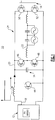
- FIG. 1 is illustrates a photovoltaic inverter 10 topology that is known in the art.
- Photovoltaic inverter 10 employs a two-stage power circuit to convert a varying DC voltage of a PV array 12 to a fixed frequency AC voltage for a power grid 14.
- Photovoltaic inverter 10 uses a DC link 16 to implement the intermediate energy storage step. This means the PV inverter 10 first converts the unstable PV DC voltage 18 to a stable DC voltage 20 that is greater than the grid voltage via a boost converter, and subsequently converts the stable DC voltage 20 to a current 22 via a PWM circuit 24 that can then be injected into the grid 14.
- Photovoltaic inverter 10 topology employs five switching devices 44, 46, 48, 50, 52 that are switching at a high frequency and that undesirably contribute to the overall switching losses of the two-stage converter.
- FIG. 2 illustrates a photovoltaic inverter 30 hard-switching topology according to one embodiment of the invention.
- Photovoltaic inverter 30 topology overcomes the necessity to employ a DC link to implement an intermediate energy storage step such as described above with reference to Figure 1 , because PV inverter 30 topology converts the PV array 12 voltage immediately into a current 32 that is the equivalent of a rectified grid current. This feature is implemented by stiffening the PV array 12 with a large capacitance 34, effectively shifting the DC link to the PV array 12. The subsequent inverter stage 36 merely needs to unfold the current 32 into the grid 14, and does so without switching losses.
- the first stage 40 is thus the only stage that has switching losses from a single device 42 verses the traditional converter that has five switching devices 44, 46, 48, 50, 52 such as depicted in Figure 1 that have switching losses.
- Photovoltaic inverter 30 is configured to operate in a boost mode at low input voltages by switching devices 54, 56 and maintaining device 40 on, thereby eliminating it's switching losses, so that devices 54 and 56 will be the only devices contributing to the switching losses during this boost mode only.
- photovoltaic inverter 30 utilizes a single high speed switch 42 when it operates in a buck mode described in further detail below. Photovoltaic inverter 30 also utilizes a pair of high speed switches 54, 56 when it operates in a boost mode described in detail below.
- a photovoltaic inverter 30 topology advantageously functions with a significant reduction in the number of power electronic devices that will be switching at a high frequency at any point in time. This feature provides an additional benefit that results due to lower conduction losses associated with slower devices that can be selected to complete the inverter system.
- Photovoltaic inverter 10 shown in Figure 1 employs three switches and two inductors in series verses the photovoltaic inverter 30 shown in Figure 2 that has three switches, one of which is optimized for very low conduction losses, and only one inductor 58.
- the photovoltaic array source 12 is stiffened via a large capacitance 34 such as described above.
- This large capacitance 34 advantageously does not compromise the safety aspects of the system as the PV source 12 is current limited.
- Attached to the capacitor 34 is the first stage buck converter 40 that creates a full wave rectified sine current in the main inductor 58. This current is then unfolded into the grid 14 by the full bridge inverter 36 connected to the output of the PV inverter 30.
- the PV inverter 30 topology was found to provide suitable working results so long as the PV source voltage remains higher than the grid voltage.
- the operation of the PV inverter 30 is configured to ensure that the current in the main inductor 58 always flows from the PV source 12 to the grid 14. This is achieved by turning on the bucking switch 42 continuously and high frequency switching the two low side devices 54, 56 of the full bridge inverter 36 using conventional Pulse Width Modulation (PWM) techniques.
- PWM Pulse Width Modulation
- the PV inverter 30 thus operates in a boost mode when the PV source 12 voltage is less than the grid 14 voltage. This boost mode advantageously is active only during the portion of the sine wave output voltage that is higher than the PV source 12 voltage.
- the bottom left switch 62 is permanently turned on, the bottom right switch 64 is permanently turned off, and the upper two switches 54, 56 are modulated to generate a boosting current that is injected into the grid 14.
- the bottom right switch 64 is permanently turned on, the bottom left switch 62 is permanently turned off, and the upper two switches 54, 56 are modulated to shape the boosting current and inject the boosting current into the grid 14.
- Inverter 36 can just as easily function to generate the requisite boosting current by turning the upper right switch 56 on during the negative portion of the rectification cycle while the upper left switch 54 is turned off, and then modulating the lower two switches 62, 64 to shape the boosting current and inject the boosting current into the grid 14.
- the lower two switches 62, 64 are modulated to generate the boosting current, the upper left switch 54 is then turned on during the positive portion of the rectification cycle.
- Figure 3 is a graph illustrating simulated inverter performance for a photovoltaic inverter hard-switching topology according to one embodiment of the invention.
- the inverter efficiency can be seen to range between 90% and close to 98% when generating output power levels between about 150 Watts and about 3000 Watts using the buck-boost duty cycle depicted in Figure 4 .
- Photovoltaic inverter 30 can just as easily be implemented using soft-switching techniques to further improve conversion efficiency according to another embodiment of the invention that also employs the same low number of devices switching at a high frequency.
- the use of soft switching topology allows slower devices having lower conduction losses to be selected for use in the current 32 unfolding portion of the respective PV inverter.
- PV inverter 30 utilizes a topology well suited to use of adaptive digital control methods for seeking the most efficient operating point for the system based on operating conditions such as, without limitation, temperature, input voltage and load power level.
- a PV inverter 70 topology includes a ripple current cancellation circuit 72 that provides a means for reducing the main inductor 58 size without compromising the output ripple current requirements of the system.
- Ripple current cancellation circuit 72 allows use of a smaller inductor 58 having lower losses than that achievable with a larger inductor, and also allows use of quasi resonant switching, significantly reducing switching losses of the main device 42.
- PV inverter 30, 70 topologies include without limitation, buck and boost capabilities incorporated into a single DC to AC converter without employment of a conventional buck/boost topology.
- Other advantages include, without limitation, the use of multiple technologies within a single PV inverter to enhance the high efficiency topology, such as the ripple current cancelation capabilities described above with reference to Figure 5 , the use of quasi-resonant switching, a topology that is well suited to use of adaptive digital control methods for seeking the most efficient operating point for the system based on operating conditions such as, without limitation, temperature, input voltage and load power level, and optional step activation of the AC contactor.
Landscapes
- Engineering & Computer Science (AREA)
- Power Engineering (AREA)
- Inverter Devices (AREA)
- Dc-Dc Converters (AREA)
Claims (5)
- Inverseur photovoltaïque (PV) (30) comprenant :un convertisseur abaisseur (40) configuré pour générer un courant à onde sinusoïdale redressé (32) en réponse à une tension électrique de réseau PV (12) et à une tension de réseau public (14) disponibles ; etun circuit de dépliage de courant (36) configuré pour commander le courant injecté dans un réseau public (14) en réponse au courant à onde sinusoïdale redressé (32) chaque fois que la tension du réseau PV (12) plus une marge de fonctionnement du convertisseur (40) sont supérieures à la tension du réseau public (14) ;ledit inverseur PV (30) comprenant en outre un condensateur de renfort (34) entre le réseau PV (12) et le convertisseur abaisseur (40), le condensateur de renfort (34) étant configuré conjointement avec le convertisseur abaisseur (40) pour générer le courant à onde sinusoïdale redressé (32) en l'absence d'une liaison CC entre le convertisseur abaisseur (40) et le circuit de dépliage de courant (36) ;dans lequel le convertisseur abaisseur (40) ne comprend pas plus d'un dispositif de commutation à haute fréquence (42) et le circuit de dépliage de courant (36) ne comprend pas plus de deux dispositifs de commutation à haute fréquence (54, 56) et dans lequel en outre les pas plus de deux dispositifs de commutation à haute fréquence (54, 56) sont configurés pour se commuter à haute fréquence uniquement lorsque la tension du réseau PV (12) plus la marge de fonctionnement du convertisseur (40) sont inférieures à la tension instantanée du réseau public (14).
- Inverseur PV (30) selon la revendication 1, dans lequel le convertisseur abaisseur (40) est maintenu pour arrêter la commutation et le circuit de dépliage de courant (36) est configuré pour fonctionner en mode de survoltage à des tensions du réseau PV (12) plus la marge de fonctionnement du convertisseur (40) inférieures à la tension du réseau public (14) et en mode d'abaissement avec un déplieur de sortie (36) à des tensions du réseau PV (12) plus la marge de fonctionnement du convertisseur (40) supérieures à la tension du réseau public (14).
- Inverseur PV (30) selon l'une quelconque des revendications précédentes, dans lequel le pas plus d'un dispositif de commutation à haute fréquence (42) est le seul dispositif de commutation de l'inverseur PV opérant en mode de commutation à haute fréquence lorsque l'inverseur PV (30) fonctionne en mode d'abaissement.
- Inverseur PV (30) selon l'une quelconque des revendications précédentes, comprenant en outre un dispositif de commande numérique adaptatif configuré pour ajuster une fréquence de commutation d'abaissement-survoltage associée au convertisseur abaisseur (40) et au circuit de dépliage de courant (36) en réponse à des caractéristiques opérationnelles souhaitées pour obtenir une efficacité de l'inverseur PV (30) supérieure à celle que l'on peut obtenir en utilisant des techniques d'inverseur PV (30) à fréquence de commutation fixe.
- Inverseur PV (30) selon la revendication 4, dans lequel les caractéristiques opérationnelles souhaitées sont choisies parmi les niveaux de tension du réseau PV, les températures de fonctionnement ambiantes de l'inverseur PV, les températures du dispositif de commutation de l'inverseur PV et les niveaux d'énergie du réseau.
Applications Claiming Priority (1)
| Application Number | Priority Date | Filing Date | Title |
|---|---|---|---|
| US12/215,505 US8023297B2 (en) | 2008-06-27 | 2008-06-27 | High efficiency photovoltaic inverter |
Publications (2)
| Publication Number | Publication Date |
|---|---|
| EP2139104A1 EP2139104A1 (fr) | 2009-12-30 |
| EP2139104B1 true EP2139104B1 (fr) | 2017-10-04 |
Family
ID=41138621
Family Applications (1)
| Application Number | Title | Priority Date | Filing Date |
|---|---|---|---|
| EP09163101.0A Active EP2139104B1 (fr) | 2008-06-27 | 2009-06-18 | Inverseur photovoltaïque haute efficacité avec un convertisseur abaisseur |
Country Status (4)
| Country | Link |
|---|---|
| US (1) | US8023297B2 (fr) |
| EP (1) | EP2139104B1 (fr) |
| CN (1) | CN101615859B (fr) |
| AU (1) | AU2009202490B2 (fr) |
Cited By (39)
| Publication number | Priority date | Publication date | Assignee | Title |
|---|---|---|---|---|
| US10637393B2 (en) | 2006-12-06 | 2020-04-28 | Solaredge Technologies Ltd. | Distributed power harvesting systems using DC power sources |
| US10644589B2 (en) | 2007-12-05 | 2020-05-05 | Solaredge Technologies Ltd. | Parallel connected inverters |
| US10666125B2 (en) | 2011-01-12 | 2020-05-26 | Solaredge Technologies Ltd. | Serially connected inverters |
| US10673222B2 (en) | 2010-11-09 | 2020-06-02 | Solaredge Technologies Ltd. | Arc detection and prevention in a power generation system |
| US10673229B2 (en) | 2010-11-09 | 2020-06-02 | Solaredge Technologies Ltd. | Arc detection and prevention in a power generation system |
| US10673253B2 (en) | 2006-12-06 | 2020-06-02 | Solaredge Technologies Ltd. | Battery power delivery module |
| US10693415B2 (en) | 2007-12-05 | 2020-06-23 | Solaredge Technologies Ltd. | Testing of a photovoltaic panel |
| US10931119B2 (en) | 2012-01-11 | 2021-02-23 | Solaredge Technologies Ltd. | Photovoltaic module |
| US10931228B2 (en) | 2010-11-09 | 2021-02-23 | Solaredge Technologies Ftd. | Arc detection and prevention in a power generation system |
| US10969412B2 (en) | 2009-05-26 | 2021-04-06 | Solaredge Technologies Ltd. | Theft detection and prevention in a power generation system |
| US10992238B2 (en) | 2012-01-30 | 2021-04-27 | Solaredge Technologies Ltd. | Maximizing power in a photovoltaic distributed power system |
| US11002774B2 (en) | 2006-12-06 | 2021-05-11 | Solaredge Technologies Ltd. | Monitoring of distributed power harvesting systems using DC power sources |
| US11018623B2 (en) | 2016-04-05 | 2021-05-25 | Solaredge Technologies Ltd. | Safety switch for photovoltaic systems |
| US11031861B2 (en) | 2006-12-06 | 2021-06-08 | Solaredge Technologies Ltd. | System and method for protection during inverter shutdown in distributed power installations |
| US11063440B2 (en) | 2006-12-06 | 2021-07-13 | Solaredge Technologies Ltd. | Method for distributed power harvesting using DC power sources |
| US11177663B2 (en) | 2016-04-05 | 2021-11-16 | Solaredge Technologies Ltd. | Chain of power devices |
| US11183922B2 (en) | 2006-12-06 | 2021-11-23 | Solaredge Technologies Ltd. | Distributed power harvesting systems using DC power sources |
| US11183968B2 (en) | 2012-01-30 | 2021-11-23 | Solaredge Technologies Ltd. | Photovoltaic panel circuitry |
| US11264947B2 (en) | 2007-12-05 | 2022-03-01 | Solaredge Technologies Ltd. | Testing of a photovoltaic panel |
| US11296650B2 (en) | 2006-12-06 | 2022-04-05 | Solaredge Technologies Ltd. | System and method for protection during inverter shutdown in distributed power installations |
| US11309832B2 (en) | 2006-12-06 | 2022-04-19 | Solaredge Technologies Ltd. | Distributed power harvesting systems using DC power sources |
| US11424616B2 (en) | 2008-05-05 | 2022-08-23 | Solaredge Technologies Ltd. | Direct current power combiner |
| US11569660B2 (en) | 2006-12-06 | 2023-01-31 | Solaredge Technologies Ltd. | Distributed power harvesting systems using DC power sources |
| US11569659B2 (en) | 2006-12-06 | 2023-01-31 | Solaredge Technologies Ltd. | Distributed power harvesting systems using DC power sources |
| US11579235B2 (en) | 2006-12-06 | 2023-02-14 | Solaredge Technologies Ltd. | Safety mechanisms, wake up and shutdown methods in distributed power installations |
| US11594968B2 (en) | 2007-08-06 | 2023-02-28 | Solaredge Technologies Ltd. | Digital average input current control in power converter |
| US11687112B2 (en) | 2006-12-06 | 2023-06-27 | Solaredge Technologies Ltd. | Distributed power harvesting systems using DC power sources |
| US11728768B2 (en) | 2006-12-06 | 2023-08-15 | Solaredge Technologies Ltd. | Pairing of components in a direct current distributed power generation system |
| US11735910B2 (en) | 2006-12-06 | 2023-08-22 | Solaredge Technologies Ltd. | Distributed power system using direct current power sources |
| US11855231B2 (en) | 2006-12-06 | 2023-12-26 | Solaredge Technologies Ltd. | Distributed power harvesting systems using DC power sources |
| US11881814B2 (en) | 2005-12-05 | 2024-01-23 | Solaredge Technologies Ltd. | Testing of a photovoltaic panel |
| US12003107B2 (en) | 2013-03-14 | 2024-06-04 | Solaredge Technologies Ltd. | Method and apparatus for storing and depleting energy |
| US12027970B2 (en) | 2006-12-06 | 2024-07-02 | Solaredge Technologies Ltd. | Safety mechanisms, wake up and shutdown methods in distributed power installations |
| US12027849B2 (en) | 2006-12-06 | 2024-07-02 | Solaredge Technologies Ltd. | Distributed power system using direct current power sources |
| US12057807B2 (en) | 2016-04-05 | 2024-08-06 | Solaredge Technologies Ltd. | Chain of power devices |
| US12418177B2 (en) | 2009-10-24 | 2025-09-16 | Solaredge Technologies Ltd. | Distributed power system using direct current power sources |
| US12633754B2 (en) | 2012-01-30 | 2026-05-19 | Solaredge Technologies Ltd. | Maximizing power in a photovoltaic distributed power system |
| US12665546B2 (en) | 2011-01-28 | 2026-06-23 | Solaredge Technologies Ltd. | Pairing of components in a direct current distributed power generation system |
| US12676488B2 (en) | 2006-12-06 | 2026-07-07 | Solaredge Technologies Ltd. | System and method for protection during inverter shutdown in distributed power installations |
Families Citing this family (23)
| Publication number | Priority date | Publication date | Assignee | Title |
|---|---|---|---|---|
| DE102009047936A1 (de) * | 2009-10-01 | 2011-04-07 | Dr. Johannes Heidenhain Gmbh | Verfahren zum Betreiben eines Wechselrichters und Wechselrichter |
| AU2010310944A1 (en) * | 2009-10-29 | 2012-06-14 | Watts & More Ltd. | Energy collection system and method |
| WO2011140366A2 (fr) * | 2010-05-06 | 2011-11-10 | Xandex, Inc. | Commande de l'ondulation de tension de sortie pour convertisseur continu-continu |
| CN101976965B (zh) * | 2010-10-08 | 2013-04-03 | 江苏博纬新能源科技有限公司 | 直流跟踪控制的大功率光伏并网逆变器 |
| CN102088192B (zh) * | 2011-03-02 | 2013-01-02 | 中南大学 | 单相单级电流型光伏并网逆变器及其控制方法 |
| CN102684522A (zh) * | 2011-03-09 | 2012-09-19 | 上海康威特吉能源技术有限公司 | 一种非隔离光伏并网逆变器及其控制方法 |
| EP2549635B1 (fr) | 2011-07-20 | 2018-12-05 | Solaredge Technologies Ltd. | Systèmes de collecte d'énergie distribuée utilisant des sources de courant continu |
| CN102291028A (zh) * | 2011-08-17 | 2011-12-21 | 福州大学 | 基于有源功率因数校正芯片控制的微功率并网逆变器 |
| CN102624030A (zh) * | 2012-03-29 | 2012-08-01 | 东南大学 | 一种光伏/蓄电池混合式电流逆变型分布发电系统 |
| US8896182B2 (en) | 2012-04-05 | 2014-11-25 | General Electric Corporation | System for driving a piezoelectric load and method of making same |
| AT512983B1 (de) * | 2012-06-13 | 2014-06-15 | Fronius Int Gmbh | Verfahren zur Prüfung einer Trennstelle eines Photovoltaik-Wechselrichters und Photovoltaik-Wechselrichter |
| US8958217B2 (en) | 2012-06-15 | 2015-02-17 | General Electric Company | System for driving a piezoelectric load and method of making same |
| CN102751742B (zh) * | 2012-07-25 | 2014-03-26 | 漳州科华技术有限责任公司 | 一种可变开关频率提高并网性能的方法 |
| CN103009989B (zh) * | 2012-12-14 | 2015-09-16 | 东南大学 | 一种混合式电流源型能量传输与驱动设备 |
| CN103746561B (zh) * | 2013-12-17 | 2016-04-13 | 中国船舶重工集团公司第七一九研究所 | 一种基于脉宽劈分的高频隔离型变频装置及其控制方法 |
| US10447040B2 (en) | 2014-10-15 | 2019-10-15 | Cummins Power Generation Ip, Inc. | Programmable inverter for controllable grid response |
| KR102308628B1 (ko) * | 2015-01-21 | 2021-10-05 | 삼성에스디아이 주식회사 | 하이브리드 전력변환 시스템 및 이를 이용하는 최대 효율 결정 방법 |
| CN105305858B (zh) * | 2015-11-18 | 2018-01-09 | 保定嘉盛光电科技股份有限公司 | 自适应光伏逆变器 |
| CN106208786A (zh) * | 2016-08-25 | 2016-12-07 | 苏州苏宝新能源科技有限公司 | 具有自放电、h桥逆变和电源防雷功能的太阳能空调系统 |
| CN108169596B (zh) * | 2017-12-22 | 2020-08-28 | 湖南科比特电气技术有限公司 | 一种光伏逆变器输入电流通道的校准系统及应用所述校准系统进行校准的方法 |
| CN108418416A (zh) * | 2018-03-19 | 2018-08-17 | 盐城工学院 | 一种部分功率处理升压单元与并网逆变器的协同控制方法 |
| CN108695928B (zh) * | 2018-05-28 | 2020-08-04 | 武汉天富海科技发展有限公司 | 一种隔离式光伏充电装置与方法 |
| CN114498746A (zh) * | 2022-01-28 | 2022-05-13 | 浙江腾圣储能技术有限公司 | 逆变器电路、逆变器、逆变器控制方法及光伏系统 |
Family Cites Families (7)
| Publication number | Priority date | Publication date | Assignee | Title |
|---|---|---|---|---|
| DE10063538C1 (de) * | 2000-12-20 | 2003-03-13 | Ascom Energy Systems Ag Bern | Verfahren zur Datenübertragung in Wechselstromnetzen |
| US6556462B1 (en) | 2002-06-28 | 2003-04-29 | General Electric Company | High power factor converter with a boost circuit having continuous/discontinuous modes |
| US6693805B1 (en) | 2002-07-31 | 2004-02-17 | Lockheed Martin Corporation | Ripple cancellation circuit for ultra-low-noise power supplies |
| US7099169B2 (en) * | 2003-02-21 | 2006-08-29 | Distributed Power, Inc. | DC to AC inverter with single-switch bipolar boost circuit |
| US7016205B2 (en) | 2003-10-01 | 2006-03-21 | General Electric Company | Ripple-current reduction schemes for AC converters |
| US20050139259A1 (en) | 2003-12-30 | 2005-06-30 | Robert Steigerwald | Transformerless power conversion in an inverter for a photovoltaic system |
| TW200709544A (en) * | 2005-08-29 | 2007-03-01 | Ind Tech Res Inst | Transformer-free power conversion circuit for parallel connection with commercial electricity system |
-
2008
- 2008-06-27 US US12/215,505 patent/US8023297B2/en active Active
-
2009
- 2009-06-18 EP EP09163101.0A patent/EP2139104B1/fr active Active
- 2009-06-22 AU AU2009202490A patent/AU2009202490B2/en active Active
- 2009-06-26 CN CN200910146279.3A patent/CN101615859B/zh not_active Expired - Fee Related
Non-Patent Citations (1)
| Title |
|---|
| None * |
Cited By (85)
| Publication number | Priority date | Publication date | Assignee | Title |
|---|---|---|---|---|
| US11881814B2 (en) | 2005-12-05 | 2024-01-23 | Solaredge Technologies Ltd. | Testing of a photovoltaic panel |
| US11962243B2 (en) | 2006-12-06 | 2024-04-16 | Solaredge Technologies Ltd. | Method for distributed power harvesting using DC power sources |
| US11961922B2 (en) | 2006-12-06 | 2024-04-16 | Solaredge Technologies Ltd. | Distributed power harvesting systems using DC power sources |
| US12316274B2 (en) | 2006-12-06 | 2025-05-27 | Solaredge Technologies Ltd. | Pairing of components in a direct current distributed power generation system |
| US12281919B2 (en) | 2006-12-06 | 2025-04-22 | Solaredge Technologies Ltd. | Monitoring of distributed power harvesting systems using DC power sources |
| US10673253B2 (en) | 2006-12-06 | 2020-06-02 | Solaredge Technologies Ltd. | Battery power delivery module |
| US12276997B2 (en) | 2006-12-06 | 2025-04-15 | Solaredge Technologies Ltd. | Distributed power harvesting systems using DC power sources |
| US12224706B2 (en) | 2006-12-06 | 2025-02-11 | Solaredge Technologies Ltd. | Pairing of components in a direct current distributed power generation system |
| US12107417B2 (en) | 2006-12-06 | 2024-10-01 | Solaredge Technologies Ltd. | Distributed power harvesting systems using DC power sources |
| US12068599B2 (en) | 2006-12-06 | 2024-08-20 | Solaredge Technologies Ltd. | System and method for protection during inverter shutdown in distributed power installations |
| US12046940B2 (en) | 2006-12-06 | 2024-07-23 | Solaredge Technologies Ltd. | Battery power control |
| US11002774B2 (en) | 2006-12-06 | 2021-05-11 | Solaredge Technologies Ltd. | Monitoring of distributed power harvesting systems using DC power sources |
| US12032080B2 (en) | 2006-12-06 | 2024-07-09 | Solaredge Technologies Ltd. | Safety mechanisms, wake up and shutdown methods in distributed power installations |
| US11031861B2 (en) | 2006-12-06 | 2021-06-08 | Solaredge Technologies Ltd. | System and method for protection during inverter shutdown in distributed power installations |
| US11043820B2 (en) | 2006-12-06 | 2021-06-22 | Solaredge Technologies Ltd. | Battery power delivery module |
| US11063440B2 (en) | 2006-12-06 | 2021-07-13 | Solaredge Technologies Ltd. | Method for distributed power harvesting using DC power sources |
| US12027849B2 (en) | 2006-12-06 | 2024-07-02 | Solaredge Technologies Ltd. | Distributed power system using direct current power sources |
| US11073543B2 (en) | 2006-12-06 | 2021-07-27 | Solaredge Technologies Ltd. | Monitoring of distributed power harvesting systems using DC power sources |
| US12027970B2 (en) | 2006-12-06 | 2024-07-02 | Solaredge Technologies Ltd. | Safety mechanisms, wake up and shutdown methods in distributed power installations |
| US11183922B2 (en) | 2006-12-06 | 2021-11-23 | Solaredge Technologies Ltd. | Distributed power harvesting systems using DC power sources |
| US11658482B2 (en) | 2006-12-06 | 2023-05-23 | Solaredge Technologies Ltd. | Distributed power harvesting systems using DC power sources |
| US12388492B2 (en) | 2006-12-06 | 2025-08-12 | Solaredge Technologies Ltd. | Safety mechanisms, wake up and shutdown methods in distributed power installations |
| US12676488B2 (en) | 2006-12-06 | 2026-07-07 | Solaredge Technologies Ltd. | System and method for protection during inverter shutdown in distributed power installations |
| US10637393B2 (en) | 2006-12-06 | 2020-04-28 | Solaredge Technologies Ltd. | Distributed power harvesting systems using DC power sources |
| US11855231B2 (en) | 2006-12-06 | 2023-12-26 | Solaredge Technologies Ltd. | Distributed power harvesting systems using DC power sources |
| US11735910B2 (en) | 2006-12-06 | 2023-08-22 | Solaredge Technologies Ltd. | Distributed power system using direct current power sources |
| US11296650B2 (en) | 2006-12-06 | 2022-04-05 | Solaredge Technologies Ltd. | System and method for protection during inverter shutdown in distributed power installations |
| US11309832B2 (en) | 2006-12-06 | 2022-04-19 | Solaredge Technologies Ltd. | Distributed power harvesting systems using DC power sources |
| US11728768B2 (en) | 2006-12-06 | 2023-08-15 | Solaredge Technologies Ltd. | Pairing of components in a direct current distributed power generation system |
| US11687112B2 (en) | 2006-12-06 | 2023-06-27 | Solaredge Technologies Ltd. | Distributed power harvesting systems using DC power sources |
| US11476799B2 (en) | 2006-12-06 | 2022-10-18 | Solaredge Technologies Ltd. | Distributed power harvesting systems using DC power sources |
| US11682918B2 (en) | 2006-12-06 | 2023-06-20 | Solaredge Technologies Ltd. | Battery power delivery module |
| US11569660B2 (en) | 2006-12-06 | 2023-01-31 | Solaredge Technologies Ltd. | Distributed power harvesting systems using DC power sources |
| US11569659B2 (en) | 2006-12-06 | 2023-01-31 | Solaredge Technologies Ltd. | Distributed power harvesting systems using DC power sources |
| US11575260B2 (en) | 2006-12-06 | 2023-02-07 | Solaredge Technologies Ltd. | Distributed power harvesting systems using DC power sources |
| US11575261B2 (en) | 2006-12-06 | 2023-02-07 | Solaredge Technologies Ltd. | Distributed power harvesting systems using DC power sources |
| US11579235B2 (en) | 2006-12-06 | 2023-02-14 | Solaredge Technologies Ltd. | Safety mechanisms, wake up and shutdown methods in distributed power installations |
| US11594881B2 (en) | 2006-12-06 | 2023-02-28 | Solaredge Technologies Ltd. | Distributed power harvesting systems using DC power sources |
| US11598652B2 (en) | 2006-12-06 | 2023-03-07 | Solaredge Technologies Ltd. | Monitoring of distributed power harvesting systems using DC power sources |
| US11594882B2 (en) | 2006-12-06 | 2023-02-28 | Solaredge Technologies Ltd. | Distributed power harvesting systems using DC power sources |
| US11594880B2 (en) | 2006-12-06 | 2023-02-28 | Solaredge Technologies Ltd. | Distributed power harvesting systems using DC power sources |
| US11594968B2 (en) | 2007-08-06 | 2023-02-28 | Solaredge Technologies Ltd. | Digital average input current control in power converter |
| US11183923B2 (en) | 2007-12-05 | 2021-11-23 | Solaredge Technologies Ltd. | Parallel connected inverters |
| US10693415B2 (en) | 2007-12-05 | 2020-06-23 | Solaredge Technologies Ltd. | Testing of a photovoltaic panel |
| US10644589B2 (en) | 2007-12-05 | 2020-05-05 | Solaredge Technologies Ltd. | Parallel connected inverters |
| US12055647B2 (en) | 2007-12-05 | 2024-08-06 | Solaredge Technologies Ltd. | Parallel connected inverters |
| US11693080B2 (en) | 2007-12-05 | 2023-07-04 | Solaredge Technologies Ltd. | Parallel connected inverters |
| US11183969B2 (en) | 2007-12-05 | 2021-11-23 | Solaredge Technologies Ltd. | Testing of a photovoltaic panel |
| US11264947B2 (en) | 2007-12-05 | 2022-03-01 | Solaredge Technologies Ltd. | Testing of a photovoltaic panel |
| US11894806B2 (en) | 2007-12-05 | 2024-02-06 | Solaredge Technologies Ltd. | Testing of a photovoltaic panel |
| US11424616B2 (en) | 2008-05-05 | 2022-08-23 | Solaredge Technologies Ltd. | Direct current power combiner |
| US12218498B2 (en) | 2008-05-05 | 2025-02-04 | Solaredge Technologies Ltd. | Direct current power combiner |
| US11867729B2 (en) | 2009-05-26 | 2024-01-09 | Solaredge Technologies Ltd. | Theft detection and prevention in a power generation system |
| US12306215B2 (en) | 2009-05-26 | 2025-05-20 | Solaredge Technologies Ltd. | Theft detection and prevention in a power generation system |
| US10969412B2 (en) | 2009-05-26 | 2021-04-06 | Solaredge Technologies Ltd. | Theft detection and prevention in a power generation system |
| US12418177B2 (en) | 2009-10-24 | 2025-09-16 | Solaredge Technologies Ltd. | Distributed power system using direct current power sources |
| US10673229B2 (en) | 2010-11-09 | 2020-06-02 | Solaredge Technologies Ltd. | Arc detection and prevention in a power generation system |
| US12003215B2 (en) | 2010-11-09 | 2024-06-04 | Solaredge Technologies Ltd. | Arc detection and prevention in a power generation system |
| US11489330B2 (en) | 2010-11-09 | 2022-11-01 | Solaredge Technologies Ltd. | Arc detection and prevention in a power generation system |
| US11070051B2 (en) | 2010-11-09 | 2021-07-20 | Solaredge Technologies Ltd. | Arc detection and prevention in a power generation system |
| US12407158B2 (en) | 2010-11-09 | 2025-09-02 | Solaredge Technologies Ltd. | Arc detection and prevention in a power generation system |
| US10673222B2 (en) | 2010-11-09 | 2020-06-02 | Solaredge Technologies Ltd. | Arc detection and prevention in a power generation system |
| US11349432B2 (en) | 2010-11-09 | 2022-05-31 | Solaredge Technologies Ltd. | Arc detection and prevention in a power generation system |
| US10931228B2 (en) | 2010-11-09 | 2021-02-23 | Solaredge Technologies Ftd. | Arc detection and prevention in a power generation system |
| US12218505B2 (en) | 2011-01-12 | 2025-02-04 | Solaredge Technologies Ltd. | Serially connected inverters |
| US10666125B2 (en) | 2011-01-12 | 2020-05-26 | Solaredge Technologies Ltd. | Serially connected inverters |
| US11205946B2 (en) | 2011-01-12 | 2021-12-21 | Solaredge Technologies Ltd. | Serially connected inverters |
| US12665546B2 (en) | 2011-01-28 | 2026-06-23 | Solaredge Technologies Ltd. | Pairing of components in a direct current distributed power generation system |
| US11979037B2 (en) | 2012-01-11 | 2024-05-07 | Solaredge Technologies Ltd. | Photovoltaic module |
| US10931119B2 (en) | 2012-01-11 | 2021-02-23 | Solaredge Technologies Ltd. | Photovoltaic module |
| US10992238B2 (en) | 2012-01-30 | 2021-04-27 | Solaredge Technologies Ltd. | Maximizing power in a photovoltaic distributed power system |
| US11183968B2 (en) | 2012-01-30 | 2021-11-23 | Solaredge Technologies Ltd. | Photovoltaic panel circuitry |
| US11620885B2 (en) | 2012-01-30 | 2023-04-04 | Solaredge Technologies Ltd. | Photovoltaic panel circuitry |
| US12633754B2 (en) | 2012-01-30 | 2026-05-19 | Solaredge Technologies Ltd. | Maximizing power in a photovoltaic distributed power system |
| US12094306B2 (en) | 2012-01-30 | 2024-09-17 | Solaredge Technologies Ltd. | Photovoltaic panel circuitry |
| US12191668B2 (en) | 2012-01-30 | 2025-01-07 | Solaredge Technologies Ltd. | Maximizing power in a photovoltaic distributed power system |
| US12255457B2 (en) | 2013-03-14 | 2025-03-18 | Solaredge Technologies Ltd. | Method and apparatus for storing and depleting energy |
| US12003107B2 (en) | 2013-03-14 | 2024-06-04 | Solaredge Technologies Ltd. | Method and apparatus for storing and depleting energy |
| US12348182B2 (en) | 2016-04-05 | 2025-07-01 | Solaredge Technologies Ltd. | Safety switch for photovoltaic systems |
| US12057807B2 (en) | 2016-04-05 | 2024-08-06 | Solaredge Technologies Ltd. | Chain of power devices |
| US11201476B2 (en) | 2016-04-05 | 2021-12-14 | Solaredge Technologies Ltd. | Photovoltaic power device and wiring |
| US12627140B2 (en) | 2016-04-05 | 2026-05-12 | Solaredge Technologies Ltd. | Chain of power devices |
| US11870250B2 (en) | 2016-04-05 | 2024-01-09 | Solaredge Technologies Ltd. | Chain of power devices |
| US11018623B2 (en) | 2016-04-05 | 2021-05-25 | Solaredge Technologies Ltd. | Safety switch for photovoltaic systems |
| US11177663B2 (en) | 2016-04-05 | 2021-11-16 | Solaredge Technologies Ltd. | Chain of power devices |
Also Published As
| Publication number | Publication date |
|---|---|
| US20090323379A1 (en) | 2009-12-31 |
| CN101615859A (zh) | 2009-12-30 |
| AU2009202490B2 (en) | 2013-12-05 |
| AU2009202490A1 (en) | 2010-01-14 |
| CN101615859B (zh) | 2014-08-13 |
| EP2139104A1 (fr) | 2009-12-30 |
| US8023297B2 (en) | 2011-09-20 |
Similar Documents
| Publication | Publication Date | Title |
|---|---|---|
| US8023297B2 (en) | High efficiency photovoltaic inverter | |
| EP2128972B1 (fr) | Inverseur photovoltaïque multi-source haute efficacité | |
| US20200412239A1 (en) | Power converter | |
| EP3735739B1 (fr) | Convertisseur de secteur | |
| Oluwafemi et al. | A modified high output-gain cuk converter circuit configuration for renewable applications—A comprehensive investigation | |
| Xia et al. | Minimising peak current in boundary conduction mode for the four‐switch buck–boost DC/DC converter with soft switching | |
| EP3050202A2 (fr) | Convertisseur cc-cc intra-module et module photovoltaïque le comprenant | |
| Kalaiarasi et al. | Comparison of Z-source Inverter with DC-DC Boost converter fed VSI for PV applications | |
| Matiushkin et al. | Novel single-stage buck-boost inverter with unfolding circuit | |
| Salari et al. | Analysis of switched inductor three-level DC/DC converter | |
| Arunkumari et al. | A Novel single switch high step up DC–DC converter for PV based application | |
| Das | Development and Experimental Validation of a Proportional Resonant Controller for Single-Phase PFC Rectifier with Active Power Decoupling | |
| Yu et al. | Design considerations of a multiple-input isolated single ended primary inductor converter (SEPIC) for distributed generation sources | |
| Darwish et al. | Operation and control design of new Three-Phase inverters with reduced number of switches | |
| Mohammadi et al. | Performance optimisation of the grid‐connected flyback inverter under improved hybrid conduction mode | |
| Lam et al. | An asymmetrical PWM (APWM) controlled multi-input isolated resonant converter with zero voltage switching (ZVS) for hybrid renewable energy systems | |
| Mohan et al. | Switched inductor based transformerless boost inverter | |
| Makovenko et al. | Novel quasi-Z-source derived inverter with unfolding circuit and battery storage | |
| Lavanya | Modeling And Simulaton Of Three Stage Interleaved Boost Converter Based Wind Energy CONVERSION SYSTEM | |
| Rahman | A Zero-Voltage-Transition High-G Switched-Coupled-Inductor Boost Converter | |
| Baig et al. | A Soft-Switched CUK Converter Design and Analysis | |
| Jagan et al. | Voltage Amplification Redefined: Innovative Optimized High Voltage Gain Z-Network | |
| Sharma et al. | Dual-Switch High Step-Up Converter for Renewable Energy Sources | |
| Venkatesh et al. | A Streamlined Boost Converter Design and Modelling Process for Photovoltaic Systems | |
| Lotfi et al. | A Novel High Gain Transformerless DC-DC Converter with Continuous Input and Output Currents |
Legal Events
| Date | Code | Title | Description |
|---|---|---|---|
| PUAI | Public reference made under article 153(3) epc to a published international application that has entered the european phase |
Free format text: ORIGINAL CODE: 0009012 |
|
| AK | Designated contracting states |
Kind code of ref document: A1 Designated state(s): AT BE BG CH CY CZ DE DK EE ES FI FR GB GR HR HU IE IS IT LI LT LU LV MC MK MT NL NO PL PT RO SE SI SK TR |
|
| 17P | Request for examination filed |
Effective date: 20100630 |
|
| 17Q | First examination report despatched |
Effective date: 20100722 |
|
| REG | Reference to a national code |
Ref country code: DE Ref legal event code: R079 Ref document number: 602009048650 Country of ref document: DE Free format text: PREVIOUS MAIN CLASS: H02M0007538700 Ipc: H02M0001000000 |
|
| GRAP | Despatch of communication of intention to grant a patent |
Free format text: ORIGINAL CODE: EPIDOSNIGR1 |
|
| RIC1 | Information provided on ipc code assigned before grant |
Ipc: H02M 1/00 20070101AFI20170407BHEP Ipc: H02J 3/38 20060101ALI20170407BHEP Ipc: H02M 7/5387 20070101ALI20170407BHEP |
|
| INTG | Intention to grant announced |
Effective date: 20170517 |
|
| GRAS | Grant fee paid |
Free format text: ORIGINAL CODE: EPIDOSNIGR3 |
|
| GRAA | (expected) grant |
Free format text: ORIGINAL CODE: 0009210 |
|
| STAA | Information on the status of an ep patent application or granted ep patent |
Free format text: STATUS: THE PATENT HAS BEEN GRANTED |
|
| AK | Designated contracting states |
Kind code of ref document: B1 Designated state(s): AT BE BG CH CY CZ DE DK EE ES FI FR GB GR HR HU IE IS IT LI LT LU LV MC MK MT NL NO PL PT RO SE SI SK TR |
|
| REG | Reference to a national code |
Ref country code: GB Ref legal event code: FG4D |
|
| REG | Reference to a national code |
Ref country code: CH Ref legal event code: EP |
|
| REG | Reference to a national code |
Ref country code: AT Ref legal event code: REF Ref document number: 934888 Country of ref document: AT Kind code of ref document: T Effective date: 20171015 |
|
| REG | Reference to a national code |
Ref country code: IE Ref legal event code: FG4D |
|
| REG | Reference to a national code |
Ref country code: DE Ref legal event code: R096 Ref document number: 602009048650 Country of ref document: DE |
|
| REG | Reference to a national code |
Ref country code: NL Ref legal event code: MP Effective date: 20171004 |
|
| REG | Reference to a national code |
Ref country code: LT Ref legal event code: MG4D |
|
| REG | Reference to a national code |
Ref country code: AT Ref legal event code: MK05 Ref document number: 934888 Country of ref document: AT Kind code of ref document: T Effective date: 20171004 |
|
| PG25 | Lapsed in a contracting state [announced via postgrant information from national office to epo] |
Ref country code: NL Free format text: LAPSE BECAUSE OF FAILURE TO SUBMIT A TRANSLATION OF THE DESCRIPTION OR TO PAY THE FEE WITHIN THE PRESCRIBED TIME-LIMIT Effective date: 20171004 |
|
| PG25 | Lapsed in a contracting state [announced via postgrant information from national office to epo] |
Ref country code: LT Free format text: LAPSE BECAUSE OF FAILURE TO SUBMIT A TRANSLATION OF THE DESCRIPTION OR TO PAY THE FEE WITHIN THE PRESCRIBED TIME-LIMIT Effective date: 20171004 Ref country code: ES Free format text: LAPSE BECAUSE OF FAILURE TO SUBMIT A TRANSLATION OF THE DESCRIPTION OR TO PAY THE FEE WITHIN THE PRESCRIBED TIME-LIMIT Effective date: 20171004 Ref country code: SE Free format text: LAPSE BECAUSE OF FAILURE TO SUBMIT A TRANSLATION OF THE DESCRIPTION OR TO PAY THE FEE WITHIN THE PRESCRIBED TIME-LIMIT Effective date: 20171004 Ref country code: NO Free format text: LAPSE BECAUSE OF FAILURE TO SUBMIT A TRANSLATION OF THE DESCRIPTION OR TO PAY THE FEE WITHIN THE PRESCRIBED TIME-LIMIT Effective date: 20180104 Ref country code: FI Free format text: LAPSE BECAUSE OF FAILURE TO SUBMIT A TRANSLATION OF THE DESCRIPTION OR TO PAY THE FEE WITHIN THE PRESCRIBED TIME-LIMIT Effective date: 20171004 |
|
| PG25 | Lapsed in a contracting state [announced via postgrant information from national office to epo] |
Ref country code: LV Free format text: LAPSE BECAUSE OF FAILURE TO SUBMIT A TRANSLATION OF THE DESCRIPTION OR TO PAY THE FEE WITHIN THE PRESCRIBED TIME-LIMIT Effective date: 20171004 Ref country code: GR Free format text: LAPSE BECAUSE OF FAILURE TO SUBMIT A TRANSLATION OF THE DESCRIPTION OR TO PAY THE FEE WITHIN THE PRESCRIBED TIME-LIMIT Effective date: 20180105 Ref country code: BG Free format text: LAPSE BECAUSE OF FAILURE TO SUBMIT A TRANSLATION OF THE DESCRIPTION OR TO PAY THE FEE WITHIN THE PRESCRIBED TIME-LIMIT Effective date: 20180104 Ref country code: IS Free format text: LAPSE BECAUSE OF FAILURE TO SUBMIT A TRANSLATION OF THE DESCRIPTION OR TO PAY THE FEE WITHIN THE PRESCRIBED TIME-LIMIT Effective date: 20180204 Ref country code: AT Free format text: LAPSE BECAUSE OF FAILURE TO SUBMIT A TRANSLATION OF THE DESCRIPTION OR TO PAY THE FEE WITHIN THE PRESCRIBED TIME-LIMIT Effective date: 20171004 Ref country code: HR Free format text: LAPSE BECAUSE OF FAILURE TO SUBMIT A TRANSLATION OF THE DESCRIPTION OR TO PAY THE FEE WITHIN THE PRESCRIBED TIME-LIMIT Effective date: 20171004 |
|
| REG | Reference to a national code |
Ref country code: DE Ref legal event code: R097 Ref document number: 602009048650 Country of ref document: DE |
|
| PG25 | Lapsed in a contracting state [announced via postgrant information from national office to epo] |
Ref country code: DK Free format text: LAPSE BECAUSE OF FAILURE TO SUBMIT A TRANSLATION OF THE DESCRIPTION OR TO PAY THE FEE WITHIN THE PRESCRIBED TIME-LIMIT Effective date: 20171004 Ref country code: CZ Free format text: LAPSE BECAUSE OF FAILURE TO SUBMIT A TRANSLATION OF THE DESCRIPTION OR TO PAY THE FEE WITHIN THE PRESCRIBED TIME-LIMIT Effective date: 20171004 Ref country code: SK Free format text: LAPSE BECAUSE OF FAILURE TO SUBMIT A TRANSLATION OF THE DESCRIPTION OR TO PAY THE FEE WITHIN THE PRESCRIBED TIME-LIMIT Effective date: 20171004 Ref country code: EE Free format text: LAPSE BECAUSE OF FAILURE TO SUBMIT A TRANSLATION OF THE DESCRIPTION OR TO PAY THE FEE WITHIN THE PRESCRIBED TIME-LIMIT Effective date: 20171004 |
|
| PLBE | No opposition filed within time limit |
Free format text: ORIGINAL CODE: 0009261 |
|
| STAA | Information on the status of an ep patent application or granted ep patent |
Free format text: STATUS: NO OPPOSITION FILED WITHIN TIME LIMIT |
|
| PG25 | Lapsed in a contracting state [announced via postgrant information from national office to epo] |
Ref country code: PL Free format text: LAPSE BECAUSE OF FAILURE TO SUBMIT A TRANSLATION OF THE DESCRIPTION OR TO PAY THE FEE WITHIN THE PRESCRIBED TIME-LIMIT Effective date: 20171004 Ref country code: RO Free format text: LAPSE BECAUSE OF FAILURE TO SUBMIT A TRANSLATION OF THE DESCRIPTION OR TO PAY THE FEE WITHIN THE PRESCRIBED TIME-LIMIT Effective date: 20171004 Ref country code: IT Free format text: LAPSE BECAUSE OF FAILURE TO SUBMIT A TRANSLATION OF THE DESCRIPTION OR TO PAY THE FEE WITHIN THE PRESCRIBED TIME-LIMIT Effective date: 20171004 |
|
| 26N | No opposition filed |
Effective date: 20180705 |
|
| PG25 | Lapsed in a contracting state [announced via postgrant information from national office to epo] |
Ref country code: SI Free format text: LAPSE BECAUSE OF FAILURE TO SUBMIT A TRANSLATION OF THE DESCRIPTION OR TO PAY THE FEE WITHIN THE PRESCRIBED TIME-LIMIT Effective date: 20171004 |
|
| REG | Reference to a national code |
Ref country code: CH Ref legal event code: PL |
|
| GBPC | Gb: european patent ceased through non-payment of renewal fee |
Effective date: 20180618 |
|
| REG | Reference to a national code |
Ref country code: BE Ref legal event code: MM Effective date: 20180630 |
|
| REG | Reference to a national code |
Ref country code: IE Ref legal event code: MM4A |
|
| PG25 | Lapsed in a contracting state [announced via postgrant information from national office to epo] |
Ref country code: MC Free format text: LAPSE BECAUSE OF FAILURE TO SUBMIT A TRANSLATION OF THE DESCRIPTION OR TO PAY THE FEE WITHIN THE PRESCRIBED TIME-LIMIT Effective date: 20171004 Ref country code: LU Free format text: LAPSE BECAUSE OF NON-PAYMENT OF DUE FEES Effective date: 20180618 |
|
| PG25 | Lapsed in a contracting state [announced via postgrant information from national office to epo] |
Ref country code: LI Free format text: LAPSE BECAUSE OF NON-PAYMENT OF DUE FEES Effective date: 20180630 Ref country code: CH Free format text: LAPSE BECAUSE OF NON-PAYMENT OF DUE FEES Effective date: 20180630 Ref country code: GB Free format text: LAPSE BECAUSE OF NON-PAYMENT OF DUE FEES Effective date: 20180618 Ref country code: FR Free format text: LAPSE BECAUSE OF NON-PAYMENT OF DUE FEES Effective date: 20180630 Ref country code: IE Free format text: LAPSE BECAUSE OF NON-PAYMENT OF DUE FEES Effective date: 20180618 |
|
| PG25 | Lapsed in a contracting state [announced via postgrant information from national office to epo] |
Ref country code: BE Free format text: LAPSE BECAUSE OF NON-PAYMENT OF DUE FEES Effective date: 20180630 |
|
| PG25 | Lapsed in a contracting state [announced via postgrant information from national office to epo] |
Ref country code: MT Free format text: LAPSE BECAUSE OF NON-PAYMENT OF DUE FEES Effective date: 20180618 |
|
| PG25 | Lapsed in a contracting state [announced via postgrant information from national office to epo] |
Ref country code: TR Free format text: LAPSE BECAUSE OF FAILURE TO SUBMIT A TRANSLATION OF THE DESCRIPTION OR TO PAY THE FEE WITHIN THE PRESCRIBED TIME-LIMIT Effective date: 20171004 |
|
| PG25 | Lapsed in a contracting state [announced via postgrant information from national office to epo] |
Ref country code: HU Free format text: LAPSE BECAUSE OF FAILURE TO SUBMIT A TRANSLATION OF THE DESCRIPTION OR TO PAY THE FEE WITHIN THE PRESCRIBED TIME-LIMIT; INVALID AB INITIO Effective date: 20090618 Ref country code: PT Free format text: LAPSE BECAUSE OF FAILURE TO SUBMIT A TRANSLATION OF THE DESCRIPTION OR TO PAY THE FEE WITHIN THE PRESCRIBED TIME-LIMIT Effective date: 20171004 |
|
| PG25 | Lapsed in a contracting state [announced via postgrant information from national office to epo] |
Ref country code: MK Free format text: LAPSE BECAUSE OF NON-PAYMENT OF DUE FEES Effective date: 20171004 Ref country code: CY Free format text: LAPSE BECAUSE OF FAILURE TO SUBMIT A TRANSLATION OF THE DESCRIPTION OR TO PAY THE FEE WITHIN THE PRESCRIBED TIME-LIMIT Effective date: 20171004 |
|
| P01 | Opt-out of the competence of the unified patent court (upc) registered |
Effective date: 20230522 |
|
| REG | Reference to a national code |
Ref country code: DE Ref legal event code: R081 Ref document number: 602009048650 Country of ref document: DE Owner name: GE GRID SOLUTIONS LLC, ATLANTA, US Free format text: FORMER OWNER: GENERAL ELECTRIC CO., SCHENECTADY, N.Y., US |
|
| PGFP | Annual fee paid to national office [announced via postgrant information from national office to epo] |
Ref country code: DE Payment date: 20260520 Year of fee payment: 18 |