EP2139096A2 - Entraînement auxiliaire à moteur électrique pour véhicules - Google Patents
Entraînement auxiliaire à moteur électrique pour véhicules Download PDFInfo
- Publication number
- EP2139096A2 EP2139096A2 EP09008318A EP09008318A EP2139096A2 EP 2139096 A2 EP2139096 A2 EP 2139096A2 EP 09008318 A EP09008318 A EP 09008318A EP 09008318 A EP09008318 A EP 09008318A EP 2139096 A2 EP2139096 A2 EP 2139096A2
- Authority
- EP
- European Patent Office
- Prior art keywords
- housing
- plug
- contacts
- auxiliary drive
- connection
- Prior art date
- Legal status (The legal status is an assumption and is not a legal conclusion. Google has not performed a legal analysis and makes no representation as to the accuracy of the status listed.)
- Granted
Links
- 230000005540 biological transmission Effects 0.000 claims abstract description 10
- 239000000463 material Substances 0.000 claims description 2
- 230000013011 mating Effects 0.000 claims description 2
- 239000002991 molded plastic Substances 0.000 claims 1
- 239000004020 conductor Substances 0.000 abstract description 6
- 238000013461 design Methods 0.000 description 10
- 238000003780 insertion Methods 0.000 description 7
- 230000037431 insertion Effects 0.000 description 7
- 238000007789 sealing Methods 0.000 description 5
- 230000005489 elastic deformation Effects 0.000 description 3
- 238000009434 installation Methods 0.000 description 3
- 238000004519 manufacturing process Methods 0.000 description 3
- 238000010276 construction Methods 0.000 description 2
- 238000011161 development Methods 0.000 description 2
- 230000018109 developmental process Effects 0.000 description 2
- NJPPVKZQTLUDBO-UHFFFAOYSA-N novaluron Chemical compound C1=C(Cl)C(OC(F)(F)C(OC(F)(F)F)F)=CC=C1NC(=O)NC(=O)C1=C(F)C=CC=C1F NJPPVKZQTLUDBO-UHFFFAOYSA-N 0.000 description 2
- 238000012549 training Methods 0.000 description 2
- 230000007704 transition Effects 0.000 description 2
- 238000005452 bending Methods 0.000 description 1
- 230000015572 biosynthetic process Effects 0.000 description 1
- 238000009826 distribution Methods 0.000 description 1
- 238000004049 embossing Methods 0.000 description 1
- 239000007788 liquid Substances 0.000 description 1
- 239000002184 metal Substances 0.000 description 1
- 239000007769 metal material Substances 0.000 description 1
- 238000012986 modification Methods 0.000 description 1
- 230000004048 modification Effects 0.000 description 1
- 238000000465 moulding Methods 0.000 description 1
- 239000011347 resin Substances 0.000 description 1
- 229920005989 resin Polymers 0.000 description 1
- 239000003566 sealing material Substances 0.000 description 1
- 238000005476 soldering Methods 0.000 description 1
- 238000003860 storage Methods 0.000 description 1
- XLYOFNOQVPJJNP-UHFFFAOYSA-N water Substances O XLYOFNOQVPJJNP-UHFFFAOYSA-N 0.000 description 1
- 238000003466 welding Methods 0.000 description 1
Images
Classifications
-
- H—ELECTRICITY
- H02—GENERATION; CONVERSION OR DISTRIBUTION OF ELECTRIC POWER
- H02K—DYNAMO-ELECTRIC MACHINES
- H02K5/00—Casings; Enclosures; Supports
- H02K5/04—Casings or enclosures characterised by the shape, form or construction thereof
- H02K5/22—Auxiliary parts of casings not covered by groups H02K5/06-H02K5/20, e.g. shaped to form connection boxes or terminal boxes
- H02K5/225—Terminal boxes or connection arrangements
-
- H—ELECTRICITY
- H01—ELECTRIC ELEMENTS
- H01R—ELECTRICALLY-CONDUCTIVE CONNECTIONS; STRUCTURAL ASSOCIATIONS OF A PLURALITY OF MUTUALLY-INSULATED ELECTRICAL CONNECTING ELEMENTS; COUPLING DEVICES; CURRENT COLLECTORS
- H01R24/00—Two-part coupling devices, or either of their cooperating parts, characterised by their overall structure
- H01R24/005—Two-part coupling devices, or either of their cooperating parts, characterised by their overall structure requiring successive relative motions to complete the coupling, e.g. bayonet type
-
- H—ELECTRICITY
- H02—GENERATION; CONVERSION OR DISTRIBUTION OF ELECTRIC POWER
- H02K—DYNAMO-ELECTRIC MACHINES
- H02K11/00—Structural association of dynamo-electric machines with electric components or with devices for shielding, monitoring or protection
- H02K11/30—Structural association with control circuits or drive circuits
- H02K11/38—Control circuits or drive circuits associated with geared commutator motors of the worm-and-wheel type
-
- H—ELECTRICITY
- H02—GENERATION; CONVERSION OR DISTRIBUTION OF ELECTRIC POWER
- H02K—DYNAMO-ELECTRIC MACHINES
- H02K7/00—Arrangements for handling mechanical energy structurally associated with dynamo-electric machines, e.g. structural association with mechanical driving motors or auxiliary dynamo-electric machines
- H02K7/10—Structural association with clutches, brakes, gears, pulleys or mechanical starters
- H02K7/116—Structural association with clutches, brakes, gears, pulleys or mechanical starters with gears
- H02K7/1163—Structural association with clutches, brakes, gears, pulleys or mechanical starters with gears where at least two gears have non-parallel axes without having orbital motion
- H02K7/1166—Structural association with clutches, brakes, gears, pulleys or mechanical starters with gears where at least two gears have non-parallel axes without having orbital motion comprising worm and worm-wheel
Definitions
- the invention relates to an electric motor auxiliary drive according to the preamble of claim 1.
- Such auxiliary drives are used inter alia for the drive of windshield wiper systems.
- Electromotive auxiliary drives are known in various designs, for example as adjusting drives for vehicle seats, as electric drives for the opening and closing of vehicle windows and in particular as drives (windscreen wiper motors) for windscreen wiper systems of vehicles.
- the connection of the respective auxiliary drive for example, consists of an electric motor and a gear connected to this, for example, worm gear, with vehicle-side electrical supply lines and ggs.
- vehicle-side electrical control lines takes place in principle via an electrical connector, which is attached to the outside of the housing and thereby preferably on the outside of the gear housing or a cover of this gear housing.
- the connector thereby forms plug contacts, via which the connection to the vehicle-side electrical lines is produced with a matching mating connector, as well as internal plug contacts, via which the connector is connected to the housing-side contacts, namely for establishing the electrical connection to the electric motor and / or other functional elements of the auxiliary drive, for example with a control electronics, etc.
- the connector as a separate component, which is attached by suitable means, for example by screwing or latching to the housing of the electric motor auxiliary drive, so that the connector, inter alia, in relation to the occupancy of its outer plug contacts, in terms of its shape and / or size, etc to adapt to the respective requirements and wishes of customers (car manufacturers) and / or the respective installation situation of the auxiliary drive.
- a disadvantage of known auxiliary drives is also that due to the arrangement of the internal plug contacts and the housing-side contacts for the respective connector only a single installation position with a single, defined position of the outer plug contacts having portion of Connector is possible, so that different shaped connector are required for different installation environments or mounting positions or situations.
- the object of the invention is to show an electric motor auxiliary drive, which allows a reliable, but also simplified electrical and mechanical connection of the connector with the housing of the auxiliary drive, for example with the gear housing or a housing cover this gear housing and / or different mounting positions one and the same connector plug ,
- an electric motor auxiliary drive according to the patent claim 1 or 3 is formed.
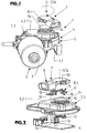
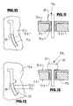
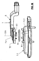
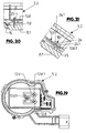
- 1 is an electric motor auxiliary drive, such as a windshield wiper drive or motor, in a known manner an electric motor 2 with motor housing 3 and a gear 4, for example worm gear with flanged to the motor housing 3 gear housing 5 includes.
- the gear housing 5 is formed in two parts, namely consisting of the housing part 5.1, which as well as the motor housing 3 is made of metal and from the housing cover 5.2, at least in his in the Figures 1 and 2 upper cover section 5.2.1 is made as a molding made of plastic.
- a connector 7 is provided, which consists in the illustrated embodiment, essentially made of a plastic connector housing 8 and accommodated in this housing electrical conductors 9, the strip-like outer connector contacts at one end Form 10 for connection to a vehicle-side connector and at another end internal plug contacts 11, via the in the manner described in more detail below an electrical, but also mechanical connection with the housing cover 5.2 and there existing cover contacts 12 is made.
- the cover contacts 12 are part of housing-internal electrical conductors 13, which the control electronics and / or the electric motor 2 with the Cover contacts 12 and thus electrically connect with the plug contacts 10 and 11 respectively.
- the conductors 9 and 13 each consist of a metal material suitable for such conductors.
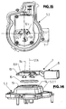
- the connector 7 or its connector housing 8 are formed on the area to be connected to the housing cover 5.2 with a connector socket 8.1, the hood-like and open at its side adjacent to the housing cover 5.2 in the assembled state.
- This open side of the plug socket 8.1 can be placed on an annular, formed on the top of the housing cover 5.2 and above this top projecting base portion 14, so that the plug socket 8.1 completely surrounds the base portion 14.
- a seal 15 formed by an O-ring the transition between the inner surface of the plug socket 8.1 and the base portion 14 made integrally with the housing cover 5.2 or with the section 5.2.1 is sealed to the outside.
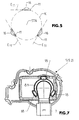
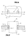
- the plug contacts 11 of the connector plug 7 project beyond the open underside of the plug socket 8.1 and are distributed at uniform angular intervals about the plug socket axis STA of the annular opening of the plug socket 8.1, in the illustrated embodiment offset by 120 ° from each other. Furthermore, the plug contacts 11 each have the same radial distance from this axis. In the illustrated embodiment, the plug contacts 11 are further each flat, that is formed as flat tabs and arranged such that the surface sides of these tabs are parallel or substantially parallel to the plug base axis STA in planes in planes, these planes also tangential to an imaginary circle K. oriented around the plug socket axis STA, as shown in the FIG. 5 is shown with the planes E 11. Each plug contact 11 is provided at least in the region of its free end with a protrusion or bulge 16 produced by embossing or in another suitable manner.
- an opening 17 is provided in the area surrounded by the base portion 14 of the housing cover 5.2, which extends in a circular segment or approximately circular segment around the axis of the annular base portion 14 and thus with mounted connector 7 to the plug socket axis STA.
- the number of openings 17 in the illustrated embodiment is equal to the number of plug contacts 11. Further, the openings 17 are provided at even angular intervals about the axis of the pedestal portion 14 and distributed around the plug pedestal axis STA, respectively, and have the same distance from that axis, i. with a total of three openings these are offset by 120 ° from each other.
- each opening 17 On the inside of the housing cover 5.2 is provided in the region of each opening 17 and congruent with this a cover contact 12, u.a. with a lid contact portion, which i.a. forms a curved slot-shaped contact opening 12.1.
- Each opening 17 is furthermore formed with an insertion region 17.1 of greater width, to which, for example, a corresponding insertion region of greater width is assigned to the cover contact 12, which merges into the slot-shaped contact opening 12.1.
- the connector plug 7 is rotated or pivoted about plug socket axis STA by a small angular amount, so that the plug contacts 11 reach the respective contact opening 12.1 of a cover contact 12 and their respective bulges 16 Cover contact 12 engage behind a form fit, so on the plug contacts 11 a bayonet-like locking of the connector plug 7 is reached on the housing cover 2.
- each slot-shaped contact opening 12 is not only adapted to its width to the thickness of the tab-like plug contacts 11, but also slightly curved, so that the respective recorded in a contact opening 12.1 originally flat plug contact 11 elastically deformed against the edge regions of the contact opening 12.1 with defined tension against the boundary surfaces of the contact opening 12 is present.
- a permanent tension and pressure between the plug contact 11 and the associated cover contact 12 and the resulting high contact reliability are achieved.
- the sealing ring 15 remains after the assembly of the connector 7 under pressure, so that the sealing function of the seal 15 remains permanently ensured.
- connection plug 7 For additional mechanical latching of the connection plug 7 on the housing cover 5.2, three snap hooks 18 are provided on the plug socket 8.1, which protrude beyond the circumference of the plug socket 8.1 and latch onto latching lugs 19, which are integrally formed on the outer surface of the housing cover 5.2.
- connection between the connector 7 and the housing cover 5 numerous advantages.
- the connector 7 to the respective wishes and requirements of customers (car manufacturers) in terms of length, shape, arrangement and occupancy of the outer plug contacts 10, etc. to adapt, but by the circular arrangement of the plug contacts 11 and the associated cover contacts 12th ensures a symmetrical force distribution and thus a durable and stable electrical and mechanical connection.
- the connection between the connector 7 and the housing cover 5.2 is carried out in a simple manner by a bayonet-type locking, between the Plug contacts 11 and the cover contacts 12 and not exclusively between plastic parts, which ensures high stability and at the same time a reliable contact.
- the described construction further ensures a tightly closed design with a round sealing contour, whereby a simple seal 15 in the form of an O-ring or a molded seal or liquid seal can be used for the sealing between the plug socket and the housing cover 5.2.
- the arrangement of the plug contacts 11, the associated cover contacts 12 and the openings 17 different positions for the connector 7 are possible. With a single plug base geometry several mounting positions for the connector 7 and for the electric motor auxiliary drive 1 can be operated in a vehicle. In a three-pole design of the connector 7, as described above, resulting in a total of three different options for the orientation of the connector 7 on the gear housing 5. In a four-pole design of the connector 7 with at least four connector contacts 11 already four different options for the result Orientation of the connected to the transmission housing connector 7.
- each cover contact 12 it is also possible to provide the cover contacts several times or form each cover contact 12 with at least two about the axis of the annular base portion 4 staggered contact openings 12.1, so then by selectively using the one or the other contact opening of the cover contacts 12 give more possibilities for attachment of the connector plug 7 in different orientations.
- connection of the connector 7 to the housing cover 5.2 has the advantage that not a special connector 7 is required for each application, but it is possible with only a few different types of connectors 7, customer needs or requirements fully meet. So it is possible, for example, with two connectors 7 different training, for example, with different lengths, in a three-pole design of the connector 7 to reach six different positions for the outer plug contacts 10 having part of the connector 7, in a four-pole design of the connector 7 even a total of twelve different positions.
- the inventive construction can thus be significantly reduced the cost of storage and provision of different auxiliary drives and / or different connector 7.
- the flexibility in the production of the auxiliary drive 1 is substantially increased with the inventive design, i. It is possible to first manufacture the auxiliary drives 1 without the respective connector 7 and only at the end of the production to provide the respective auxiliary drive 1 with the customized to the wishes and / or requirements of the customer connector 7 in the also customized orientation.
- a drastic reduction in the cost of warehousing and provision of training according to the invention also allows a drastic reduction in development times and costs, and u.a. also by the possibility in each case an already produced auxiliary drive 1 also of different design, for example, with control electronics or without control electronics, with a customized to the customer requirements or requirements connector 7 to provide etc.
- FIGS. 8-17 show embodiments which also have the aforementioned advantages.
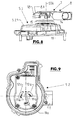
- the embodiment of the FIGS. 8-11 differs from the embodiment of the FIGS. 1-7 essentially only by a different design of the plug contacts 11a and the associated cover contacts 12a and the openings 17a.
- the plug contacts 11 a are not formed in this embodiment as flat tabs, but each provided at its free end with an angled portion 20, with which the positive bayonet connection between the plug contact 11 a and the associated cover contact 12 a is achieved.
- the openings 17a each have one to this angled shape of the plug contacts 11a adapted insertion through which each plug contact 11a can be introduced so that it protrudes with the bend 20 having the end on the inside of the housing cover 5.2 and on the local area of the associated cover contact 12a.
- the respective slot-shaped contact opening 12.1 is again adapted in width to the width of the plug contact 11a and at the same time curved like a circle segment, so that by clamping or permanent elastic deformation of an electrical connection with high contact reliability between the plug contact 11 a and the associated cover contact 12a is made.
- FIGS. 12 and 13 show as a further variant of an embodiment in which the plug contacts 11 b are each provided at two opposite edge regions with an angled portion 20, in such a way that for the respective plug contact 11 b results in an approximately S-shaped design.
- the opening 17b are adapted at its insertion to this shape.
- FIGS. 14-17 show a further embodiment, different from the embodiment of the FIGS. 1-7 again distinguished only by the formation of the plug contacts 11c and the adapted thereto embodiment of the cover contacts 12c and the openings 17c.
- the plug contacts 11c with the planes of their larger surface side are not tangential, but perpendicular to the circle K of FIG. 5 oriented, on which the Plug contacts 11c are arranged.
- the plug contacts 11 c are each provided on two opposite sides, each with an angled portion 21. The two bends 21 are each about a common side of the plug contacts 11c away.
- the plug contacts 11 c are each formed with a section 22 of reduced width to the angled portions 21.
- the shape of the plug contacts 11 c in accordance with the openings 17 c are formed.
- the contact openings 12 c. 1 of the cover contacts 12 c each have a width which is approximately equal to the width of the section 22.
- the plug contacts 11c are inserted into the openings 17c.
- the bayonet-type locking is again effected, namely by the plug contacts 11 c with their sections 22 moving into the respective contact opening 12 c 1 and the sections of greater width of the plug contacts provided with the bends 21 11c engage behind the associated cover contact 12c at the edges of its contact opening 12c.1.
- the cover contacts 12c are additionally provided with contact surfaces 23 which abut against the outer surfaces of the angled portions 21 and / or against the surface of the respective plug contact 11c in the region between these angled portions.
- FIGS. 1 to 17 While in the context of the FIGS. 1 to 17 described embodiments of the connector 7 by a bayonet-like locking of its plug contacts 11, 11 a, 11 b, 11 c with the cover contacts 12, 12 a, 12 b, 12 c is mounted on the housing cover 5.2 and this is possible even with already closed transmission housing 5, show the FIGS. 18-21 an embodiment in which the positive connection of the local connector contacts 11d with the associated cover contacts 12d by deforming or bending the cover contacts when not yet mounted housing cover 5.2 is done.
- the plug contacts 11 d and cover contacts 12 d are again in the same manner arranged relative to each other, as described inter alia for the plug contacts 11 and plug contacts 12.
- the plug contacts 11d are each formed with two flat or tab-like legs 24 which lie with their surface sides in common planes and are provided at the free end respectively with a projection or an extension 24.1, in such a way that each extension 24.1 protrudes beyond the other leg side facing away from the associated leg 24.
- the associated cover contact 12d is provided with a slot-shaped contact opening 12d.1, into which the respective socket contact 11d can be inserted, in such a way that the two extensions 24.1 each at one end of the slot-shaped contact opening 12d.1 on the inside of the housing cover 5.2 behind the Snap lid contact 12d into place.
- the cover contact 12d is further formed with a deformable tab 25, which protrudes obliquely from the lying in a plane with the inside of the housing cover 5.2 section of the cover contact 12d with not yet connected plug contact 11d and lid contact 12d.
- the tab 25 is bent into the space between the two legs 24 of the relevant plug contact 11d, so that these legs are moved apart by the tab 24 and pressed against the ends of the contact opening 12d.1 become.
- connection of the connector plug 7 with the gear housing 5 is positively effected via the plug contacts 11d and cover contacts 12d.
- the seal 15 is elastically deformed, so that the tight seal between the connector 7 and the housing cover is ensured 5.2.
- the connector 7 can be attached to the customer's wishes or requirements in accordance with different orientation on the housing cover 5.2, so that the embodiment of the FIGS. 18-21 basically has the same advantages as described above for the embodiments of FIGS. 1 to 17 were specified.
- the plug contacts 11, 11a-11d and the housing-side contacts 12, 12a-12d are made in one piece with their conductors 9 and 13 from a metallic flat material.
Landscapes
- Engineering & Computer Science (AREA)
- Power Engineering (AREA)
- Connector Housings Or Holding Contact Members (AREA)
- Motor Or Generator Frames (AREA)
Applications Claiming Priority (1)
| Application Number | Priority Date | Filing Date | Title |
|---|---|---|---|
| DE102008030739A DE102008030739A1 (de) | 2008-06-27 | 2008-06-27 | Elektromotorischer Hilfsantrieb für Fahrzeuge |
Publications (3)
| Publication Number | Publication Date |
|---|---|
| EP2139096A2 true EP2139096A2 (fr) | 2009-12-30 |
| EP2139096A3 EP2139096A3 (fr) | 2016-01-06 |
| EP2139096B1 EP2139096B1 (fr) | 2018-08-15 |
Family
ID=41119492
Family Applications (1)
| Application Number | Title | Priority Date | Filing Date |
|---|---|---|---|
| EP09008318.9A Not-in-force EP2139096B1 (fr) | 2008-06-27 | 2009-06-25 | Entraînement auxiliaire à moteur électrique pour véhicules |
Country Status (2)
| Country | Link |
|---|---|
| EP (1) | EP2139096B1 (fr) |
| DE (1) | DE102008030739A1 (fr) |
Cited By (1)
| Publication number | Priority date | Publication date | Assignee | Title |
|---|---|---|---|---|
| WO2011042233A1 (fr) * | 2009-10-05 | 2011-04-14 | Robert Bosch Gmbh | Dispositif d'essuie-glace |
Families Citing this family (1)
| Publication number | Priority date | Publication date | Assignee | Title |
|---|---|---|---|---|
| CN105164900B (zh) * | 2013-04-30 | 2019-03-15 | 株式会社美姿把 | 电机装置 |
Citations (2)
| Publication number | Priority date | Publication date | Assignee | Title |
|---|---|---|---|---|
| DE3927818C2 (fr) | 1989-08-23 | 1992-10-29 | Swf Auto-Electric Gmbh, 7120 Bietigheim-Bissingen, De | |
| FR2854023A1 (fr) | 2003-04-16 | 2004-10-22 | Valeo Systemes Dessuyage | Boitier comportant un conduit de circulation d'air empechant toute accumulation de liquide |
-
2008
- 2008-06-27 DE DE102008030739A patent/DE102008030739A1/de not_active Withdrawn
-
2009
- 2009-06-25 EP EP09008318.9A patent/EP2139096B1/fr not_active Not-in-force
Patent Citations (2)
| Publication number | Priority date | Publication date | Assignee | Title |
|---|---|---|---|---|
| DE3927818C2 (fr) | 1989-08-23 | 1992-10-29 | Swf Auto-Electric Gmbh, 7120 Bietigheim-Bissingen, De | |
| FR2854023A1 (fr) | 2003-04-16 | 2004-10-22 | Valeo Systemes Dessuyage | Boitier comportant un conduit de circulation d'air empechant toute accumulation de liquide |
Cited By (1)
| Publication number | Priority date | Publication date | Assignee | Title |
|---|---|---|---|---|
| WO2011042233A1 (fr) * | 2009-10-05 | 2011-04-14 | Robert Bosch Gmbh | Dispositif d'essuie-glace |
Also Published As
| Publication number | Publication date |
|---|---|
| EP2139096B1 (fr) | 2018-08-15 |
| EP2139096A3 (fr) | 2016-01-06 |
| DE102008030739A1 (de) | 2009-12-31 |
Similar Documents
| Publication | Publication Date | Title |
|---|---|---|
| EP0338394B1 (fr) | Moteur électrique, en particulier moteur d'essuie-glaces pour l'entraînement d'un dispositif d'essuie-glaces d'un véhicule | |
| EP2962366B1 (fr) | Connecteur électrique industriel | |
| DE10016943C2 (de) | Abschirmverbindungselement | |
| DE19500959C2 (de) | Elektrischer Steckverbinder | |
| EP2697103B1 (fr) | Systeme d'adaptateur de balai d'essuie glace | |
| DE102017113875B3 (de) | Elektrischer Stecker mit einem Schutzleiterkontakt und damit einstückig ausgebildeten Schutzleiterverbindungselement zur Erdung von Außenteilen | |
| DE3838285A1 (de) | Elektromotor, insbesondere elektrischer kleinmotor zum antrieb von scheibenwischeranlagen in kraftfahrzeugen | |
| DE102009043322A1 (de) | Elektromotorischer Hilfsantrieb | |
| DE3235622A1 (de) | Elektrischer kleinmotor, insbesondere fuer scheibenwischanlagen in kraftfahrzeugen | |
| EP2034566A2 (fr) | Connexion à fiche photovoltaïque | |
| EP2771947A1 (fr) | Connecteur électrique enfichable en deux parties | |
| DE202007016787U1 (de) | Steckdose für eine elektrische Steckverbindung | |
| DE102010007093A1 (de) | Elektrisches Gerät mit einer Durchführung eines Kabels durch eine Gehäusewand | |
| DE102014205744B4 (de) | Steuergerät für ein Fahrzeugheizgerät | |
| DE102007061011B4 (de) | Elektromotorischer Hilfsantrieb, beispielsweise Scheibenwischerantrieb | |
| EP2766977B1 (fr) | Mécanisme de commande | |
| EP2139096B1 (fr) | Entraînement auxiliaire à moteur électrique pour véhicules | |
| DE69117887T2 (de) | Abgedeckter elektrischer Verbinder | |
| DE102004036419B4 (de) | Elektromotorischer Hilfsantrieb | |
| EP1859515B1 (fr) | Douille de lampe | |
| EP1514706B1 (fr) | Fixation par encliquetage pour un boîtier | |
| EP2026418B1 (fr) | Coque de boîtier comprenant une unité de construction intégrée dotée d'au moins un composant électromécanique | |
| DE20315868U1 (de) | Lenkradhupenkontakteinheit und Baugruppe | |
| EP1612917B1 (fr) | Part d' un carter avec un élement pour compenser le jeu axial, et procédé correspondant | |
| EP1969683B1 (fr) | Ensemble de connexion enfichable |
Legal Events
| Date | Code | Title | Description |
|---|---|---|---|
| PUAI | Public reference made under article 153(3) epc to a published international application that has entered the european phase |
Free format text: ORIGINAL CODE: 0009012 |
|
| 17P | Request for examination filed |
Effective date: 20090625 |
|
| AK | Designated contracting states |
Kind code of ref document: A2 Designated state(s): AT BE BG CH CY CZ DE DK EE ES FI FR GB GR HR HU IE IS IT LI LT LU LV MC MK MT NL NO PL PT RO SE SI SK TR |
|
| PUAL | Search report despatched |
Free format text: ORIGINAL CODE: 0009013 |
|
| RIC1 | Information provided on ipc code assigned before grant |
Ipc: H02K 5/22 20060101AFI20151126BHEP Ipc: H01R 13/20 20060101ALI20151126BHEP |
|
| AK | Designated contracting states |
Kind code of ref document: A3 Designated state(s): AT BE BG CH CY CZ DE DK EE ES FI FR GB GR HR HU IE IS IT LI LT LU LV MC MK MT NL NO PL PT RO SE SI SK TR |
|
| AX | Request for extension of the european patent |
Extension state: AL BA RS |
|
| 17Q | First examination report despatched |
Effective date: 20160218 |
|
| RBV | Designated contracting states (corrected) |
Designated state(s): AT BE BG CH CY CZ DE DK EE ES FI FR GB GR HR HU IE IS IT LI LT LU LV MC MK MT NL NO PL PT RO SE SI SK TR |
|
| RIC1 | Information provided on ipc code assigned before grant |
Ipc: H01R 13/20 20060101ALI20170724BHEP Ipc: H02K 11/38 20160101ALI20170724BHEP Ipc: H01R 24/00 20110101ALI20170724BHEP Ipc: H02K 5/22 20060101AFI20170724BHEP Ipc: H02K 7/116 20060101ALI20170724BHEP |
|
| GRAP | Despatch of communication of intention to grant a patent |
Free format text: ORIGINAL CODE: EPIDOSNIGR1 |
|
| STAA | Information on the status of an ep patent application or granted ep patent |
Free format text: STATUS: GRANT OF PATENT IS INTENDED |
|
| INTG | Intention to grant announced |
Effective date: 20171002 |
|
| GRAJ | Information related to disapproval of communication of intention to grant by the applicant or resumption of examination proceedings by the epo deleted |
Free format text: ORIGINAL CODE: EPIDOSDIGR1 |
|
| STAA | Information on the status of an ep patent application or granted ep patent |
Free format text: STATUS: EXAMINATION IS IN PROGRESS |
|
| INTC | Intention to grant announced (deleted) | ||
| GRAP | Despatch of communication of intention to grant a patent |
Free format text: ORIGINAL CODE: EPIDOSNIGR1 |
|
| STAA | Information on the status of an ep patent application or granted ep patent |
Free format text: STATUS: GRANT OF PATENT IS INTENDED |
|
| INTG | Intention to grant announced |
Effective date: 20180322 |
|
| GRAS | Grant fee paid |
Free format text: ORIGINAL CODE: EPIDOSNIGR3 |
|
| GRAA | (expected) grant |
Free format text: ORIGINAL CODE: 0009210 |
|
| STAA | Information on the status of an ep patent application or granted ep patent |
Free format text: STATUS: THE PATENT HAS BEEN GRANTED |
|
| AK | Designated contracting states |
Kind code of ref document: B1 Designated state(s): AT BE BG CH CY CZ DE DK EE ES FI FR GB GR HR HU IE IS IT LI LT LU LV MC MK MT NL NO PL PT RO SE SI SK TR |
|
| REG | Reference to a national code |
Ref country code: CH Ref legal event code: EP Ref country code: GB Ref legal event code: FG4D Free format text: NOT ENGLISH Ref country code: AT Ref legal event code: REF Ref document number: 1030902 Country of ref document: AT Kind code of ref document: T Effective date: 20180815 |
|
| REG | Reference to a national code |
Ref country code: IE Ref legal event code: FG4D Free format text: LANGUAGE OF EP DOCUMENT: GERMAN |
|
| REG | Reference to a national code |
Ref country code: DE Ref legal event code: R096 Ref document number: 502009015185 Country of ref document: DE |
|
| REG | Reference to a national code |
Ref country code: CH Ref legal event code: PK Free format text: BERICHTIGUNGEN |
|
| REG | Reference to a national code |
Ref country code: NL Ref legal event code: MP Effective date: 20180815 |
|
| REG | Reference to a national code |
Ref country code: LT Ref legal event code: MG4D |
|
| RIC2 | Information provided on ipc code assigned after grant |
Ipc: H02K 5/22 20060101AFI20170724BHEP Ipc: H01R 24/00 20110101ALI20170724BHEP Ipc: H01R 13/20 20060101ALI20170724BHEP Ipc: H02K 11/38 20160101ALI20170724BHEP Ipc: H02K 7/116 20060101ALI20170724BHEP |
|
| PG25 | Lapsed in a contracting state [announced via postgrant information from national office to epo] |
Ref country code: LT Free format text: LAPSE BECAUSE OF FAILURE TO SUBMIT A TRANSLATION OF THE DESCRIPTION OR TO PAY THE FEE WITHIN THE PRESCRIBED TIME-LIMIT Effective date: 20180815 Ref country code: SE Free format text: LAPSE BECAUSE OF FAILURE TO SUBMIT A TRANSLATION OF THE DESCRIPTION OR TO PAY THE FEE WITHIN THE PRESCRIBED TIME-LIMIT Effective date: 20180815 Ref country code: BG Free format text: LAPSE BECAUSE OF FAILURE TO SUBMIT A TRANSLATION OF THE DESCRIPTION OR TO PAY THE FEE WITHIN THE PRESCRIBED TIME-LIMIT Effective date: 20181115 Ref country code: NL Free format text: LAPSE BECAUSE OF FAILURE TO SUBMIT A TRANSLATION OF THE DESCRIPTION OR TO PAY THE FEE WITHIN THE PRESCRIBED TIME-LIMIT Effective date: 20180815 Ref country code: GR Free format text: LAPSE BECAUSE OF FAILURE TO SUBMIT A TRANSLATION OF THE DESCRIPTION OR TO PAY THE FEE WITHIN THE PRESCRIBED TIME-LIMIT Effective date: 20181116 Ref country code: FI Free format text: LAPSE BECAUSE OF FAILURE TO SUBMIT A TRANSLATION OF THE DESCRIPTION OR TO PAY THE FEE WITHIN THE PRESCRIBED TIME-LIMIT Effective date: 20180815 Ref country code: IS Free format text: LAPSE BECAUSE OF FAILURE TO SUBMIT A TRANSLATION OF THE DESCRIPTION OR TO PAY THE FEE WITHIN THE PRESCRIBED TIME-LIMIT Effective date: 20181215 Ref country code: NO Free format text: LAPSE BECAUSE OF FAILURE TO SUBMIT A TRANSLATION OF THE DESCRIPTION OR TO PAY THE FEE WITHIN THE PRESCRIBED TIME-LIMIT Effective date: 20181115 |
|
| REG | Reference to a national code |
Ref country code: CH Ref legal event code: PK Free format text: BERICHTIGUNGEN |
|
| RIC2 | Information provided on ipc code assigned after grant |
Ipc: H02K 7/116 20060101ALI20170724BHEP Ipc: H01R 24/00 20110101ALI20170724BHEP Ipc: H01R 13/20 20060101ALI20170724BHEP Ipc: H02K 11/38 20160101ALI20170724BHEP Ipc: H02K 5/22 20060101AFI20170724BHEP |
|
| PG25 | Lapsed in a contracting state [announced via postgrant information from national office to epo] |
Ref country code: LV Free format text: LAPSE BECAUSE OF FAILURE TO SUBMIT A TRANSLATION OF THE DESCRIPTION OR TO PAY THE FEE WITHIN THE PRESCRIBED TIME-LIMIT Effective date: 20180815 Ref country code: HR Free format text: LAPSE BECAUSE OF FAILURE TO SUBMIT A TRANSLATION OF THE DESCRIPTION OR TO PAY THE FEE WITHIN THE PRESCRIBED TIME-LIMIT Effective date: 20180815 Ref country code: ES Free format text: LAPSE BECAUSE OF FAILURE TO SUBMIT A TRANSLATION OF THE DESCRIPTION OR TO PAY THE FEE WITHIN THE PRESCRIBED TIME-LIMIT Effective date: 20180815 |
|
| PG25 | Lapsed in a contracting state [announced via postgrant information from national office to epo] |
Ref country code: RO Free format text: LAPSE BECAUSE OF FAILURE TO SUBMIT A TRANSLATION OF THE DESCRIPTION OR TO PAY THE FEE WITHIN THE PRESCRIBED TIME-LIMIT Effective date: 20180815 Ref country code: IT Free format text: LAPSE BECAUSE OF FAILURE TO SUBMIT A TRANSLATION OF THE DESCRIPTION OR TO PAY THE FEE WITHIN THE PRESCRIBED TIME-LIMIT Effective date: 20180815 Ref country code: CZ Free format text: LAPSE BECAUSE OF FAILURE TO SUBMIT A TRANSLATION OF THE DESCRIPTION OR TO PAY THE FEE WITHIN THE PRESCRIBED TIME-LIMIT Effective date: 20180815 Ref country code: PL Free format text: LAPSE BECAUSE OF FAILURE TO SUBMIT A TRANSLATION OF THE DESCRIPTION OR TO PAY THE FEE WITHIN THE PRESCRIBED TIME-LIMIT Effective date: 20180815 Ref country code: EE Free format text: LAPSE BECAUSE OF FAILURE TO SUBMIT A TRANSLATION OF THE DESCRIPTION OR TO PAY THE FEE WITHIN THE PRESCRIBED TIME-LIMIT Effective date: 20180815 |
|
| REG | Reference to a national code |
Ref country code: DE Ref legal event code: R097 Ref document number: 502009015185 Country of ref document: DE |
|
| PG25 | Lapsed in a contracting state [announced via postgrant information from national office to epo] |
Ref country code: DK Free format text: LAPSE BECAUSE OF FAILURE TO SUBMIT A TRANSLATION OF THE DESCRIPTION OR TO PAY THE FEE WITHIN THE PRESCRIBED TIME-LIMIT Effective date: 20180815 Ref country code: SK Free format text: LAPSE BECAUSE OF FAILURE TO SUBMIT A TRANSLATION OF THE DESCRIPTION OR TO PAY THE FEE WITHIN THE PRESCRIBED TIME-LIMIT Effective date: 20180815 |
|
| PLBE | No opposition filed within time limit |
Free format text: ORIGINAL CODE: 0009261 |
|
| STAA | Information on the status of an ep patent application or granted ep patent |
Free format text: STATUS: NO OPPOSITION FILED WITHIN TIME LIMIT |
|
| 26N | No opposition filed |
Effective date: 20190516 |
|
| PG25 | Lapsed in a contracting state [announced via postgrant information from national office to epo] |
Ref country code: SI Free format text: LAPSE BECAUSE OF FAILURE TO SUBMIT A TRANSLATION OF THE DESCRIPTION OR TO PAY THE FEE WITHIN THE PRESCRIBED TIME-LIMIT Effective date: 20180815 |
|
| PG25 | Lapsed in a contracting state [announced via postgrant information from national office to epo] |
Ref country code: MC Free format text: LAPSE BECAUSE OF FAILURE TO SUBMIT A TRANSLATION OF THE DESCRIPTION OR TO PAY THE FEE WITHIN THE PRESCRIBED TIME-LIMIT Effective date: 20180815 |
|
| REG | Reference to a national code |
Ref country code: CH Ref legal event code: PL |
|
| GBPC | Gb: european patent ceased through non-payment of renewal fee |
Effective date: 20190625 |
|
| REG | Reference to a national code |
Ref country code: BE Ref legal event code: MM Effective date: 20190630 |
|
| PG25 | Lapsed in a contracting state [announced via postgrant information from national office to epo] |
Ref country code: TR Free format text: LAPSE BECAUSE OF FAILURE TO SUBMIT A TRANSLATION OF THE DESCRIPTION OR TO PAY THE FEE WITHIN THE PRESCRIBED TIME-LIMIT Effective date: 20180815 |
|
| PG25 | Lapsed in a contracting state [announced via postgrant information from national office to epo] |
Ref country code: GB Free format text: LAPSE BECAUSE OF NON-PAYMENT OF DUE FEES Effective date: 20190625 Ref country code: IE Free format text: LAPSE BECAUSE OF NON-PAYMENT OF DUE FEES Effective date: 20190625 |
|
| PG25 | Lapsed in a contracting state [announced via postgrant information from national office to epo] |
Ref country code: LI Free format text: LAPSE BECAUSE OF NON-PAYMENT OF DUE FEES Effective date: 20190630 Ref country code: CH Free format text: LAPSE BECAUSE OF NON-PAYMENT OF DUE FEES Effective date: 20190630 Ref country code: LU Free format text: LAPSE BECAUSE OF NON-PAYMENT OF DUE FEES Effective date: 20190625 Ref country code: BE Free format text: LAPSE BECAUSE OF NON-PAYMENT OF DUE FEES Effective date: 20190630 |
|
| PG25 | Lapsed in a contracting state [announced via postgrant information from national office to epo] |
Ref country code: PT Free format text: LAPSE BECAUSE OF FAILURE TO SUBMIT A TRANSLATION OF THE DESCRIPTION OR TO PAY THE FEE WITHIN THE PRESCRIBED TIME-LIMIT Effective date: 20181215 |
|
| REG | Reference to a national code |
Ref country code: AT Ref legal event code: MM01 Ref document number: 1030902 Country of ref document: AT Kind code of ref document: T Effective date: 20190625 |
|
| PG25 | Lapsed in a contracting state [announced via postgrant information from national office to epo] |
Ref country code: AT Free format text: LAPSE BECAUSE OF NON-PAYMENT OF DUE FEES Effective date: 20190625 |
|
| PG25 | Lapsed in a contracting state [announced via postgrant information from national office to epo] |
Ref country code: CY Free format text: LAPSE BECAUSE OF FAILURE TO SUBMIT A TRANSLATION OF THE DESCRIPTION OR TO PAY THE FEE WITHIN THE PRESCRIBED TIME-LIMIT Effective date: 20180815 |
|
| PG25 | Lapsed in a contracting state [announced via postgrant information from national office to epo] |
Ref country code: HU Free format text: LAPSE BECAUSE OF FAILURE TO SUBMIT A TRANSLATION OF THE DESCRIPTION OR TO PAY THE FEE WITHIN THE PRESCRIBED TIME-LIMIT; INVALID AB INITIO Effective date: 20090625 Ref country code: MT Free format text: LAPSE BECAUSE OF FAILURE TO SUBMIT A TRANSLATION OF THE DESCRIPTION OR TO PAY THE FEE WITHIN THE PRESCRIBED TIME-LIMIT Effective date: 20180815 |
|
| PGFP | Annual fee paid to national office [announced via postgrant information from national office to epo] |
Ref country code: FR Payment date: 20210630 Year of fee payment: 13 Ref country code: DE Payment date: 20210616 Year of fee payment: 13 |
|
| PG25 | Lapsed in a contracting state [announced via postgrant information from national office to epo] |
Ref country code: MK Free format text: LAPSE BECAUSE OF FAILURE TO SUBMIT A TRANSLATION OF THE DESCRIPTION OR TO PAY THE FEE WITHIN THE PRESCRIBED TIME-LIMIT Effective date: 20180815 |
|
| REG | Reference to a national code |
Ref country code: DE Ref legal event code: R119 Ref document number: 502009015185 Country of ref document: DE |
|
| PG25 | Lapsed in a contracting state [announced via postgrant information from national office to epo] |
Ref country code: FR Free format text: LAPSE BECAUSE OF NON-PAYMENT OF DUE FEES Effective date: 20220630 |
|
| PG25 | Lapsed in a contracting state [announced via postgrant information from national office to epo] |
Ref country code: DE Free format text: LAPSE BECAUSE OF NON-PAYMENT OF DUE FEES Effective date: 20230103 |
|
| P01 | Opt-out of the competence of the unified patent court (upc) registered |
Effective date: 20230528 |