EP2139077A1 - Connecteur à fiche bipolaire doté d'un élément d'étanchéité coulissant - Google Patents
Connecteur à fiche bipolaire doté d'un élément d'étanchéité coulissant Download PDFInfo
- Publication number
- EP2139077A1 EP2139077A1 EP09006654A EP09006654A EP2139077A1 EP 2139077 A1 EP2139077 A1 EP 2139077A1 EP 09006654 A EP09006654 A EP 09006654A EP 09006654 A EP09006654 A EP 09006654A EP 2139077 A1 EP2139077 A1 EP 2139077A1
- Authority
- EP
- European Patent Office
- Prior art keywords
- connector
- sealing
- sliding
- sealing element
- housing
- Prior art date
- Legal status (The legal status is an assumption and is not a legal conclusion. Google has not performed a legal analysis and makes no representation as to the accuracy of the status listed.)
- Withdrawn
Links
- 238000007789 sealing Methods 0.000 title claims abstract description 53
- 238000010276 construction Methods 0.000 description 2
- 238000009434 installation Methods 0.000 description 2
- 230000001419 dependent effect Effects 0.000 description 1
- 238000006073 displacement reaction Methods 0.000 description 1
- 239000013013 elastic material Substances 0.000 description 1
- 238000005538 encapsulation Methods 0.000 description 1
- 238000003780 insertion Methods 0.000 description 1
- 230000037431 insertion Effects 0.000 description 1
- 239000011810 insulating material Substances 0.000 description 1
- 238000009413 insulation Methods 0.000 description 1
- 238000004519 manufacturing process Methods 0.000 description 1
- 239000000463 material Substances 0.000 description 1
- 238000000034 method Methods 0.000 description 1
- 230000035515 penetration Effects 0.000 description 1
- XLYOFNOQVPJJNP-UHFFFAOYSA-N water Substances O XLYOFNOQVPJJNP-UHFFFAOYSA-N 0.000 description 1
Images


Classifications
-
- H—ELECTRICITY
- H01—ELECTRIC ELEMENTS
- H01R—ELECTRICALLY-CONDUCTIVE CONNECTIONS; STRUCTURAL ASSOCIATIONS OF A PLURALITY OF MUTUALLY-INSULATED ELECTRICAL CONNECTING ELEMENTS; COUPLING DEVICES; CURRENT COLLECTORS
- H01R13/00—Details of coupling devices of the kinds covered by groups H01R12/70 or H01R24/00 - H01R33/00
- H01R13/46—Bases; Cases
- H01R13/52—Dustproof, splashproof, drip-proof, waterproof, or flameproof cases
- H01R13/5205—Sealing means between cable and housing, e.g. grommet
- H01R13/5208—Sealing means between cable and housing, e.g. grommet having at least two cable receiving openings
-
- H—ELECTRICITY
- H01—ELECTRIC ELEMENTS
- H01R—ELECTRICALLY-CONDUCTIVE CONNECTIONS; STRUCTURAL ASSOCIATIONS OF A PLURALITY OF MUTUALLY-INSULATED ELECTRICAL CONNECTING ELEMENTS; COUPLING DEVICES; CURRENT COLLECTORS
- H01R13/00—Details of coupling devices of the kinds covered by groups H01R12/70 or H01R24/00 - H01R33/00
- H01R13/46—Bases; Cases
- H01R13/52—Dustproof, splashproof, drip-proof, waterproof, or flameproof cases
- H01R13/5219—Sealing means between coupling parts, e.g. interfacial seal
Definitions
- the invention relates to a connector consisting of two connectors, of which preferably the first is a plug-side connector (plug) and the second connector is preferably called a jack-side connector (socket), according to the preamble of claim 1.
- plug plug-side connector
- jack jack-side connector
- the connector according to the invention is particularly suitable for use in photovoltaic systems.
- the plug has a contact body with contact pins in the respective socket body or pen body.
- connectors are regularly under electrical load or under electrical voltage. It is therefore usually difficult and dangerous for a fitter or for persons who typically maintain the system to replace or install such connectors.
- a special claim on the safety of such connectors is given by a VDE requirement, namely the finger safety, which is checked with the VDE test finger. When touching the connector in the area of the contacts, the VDE test finger must not touch it in an electrically conductive manner. It is therefore necessary to choose a design that meets this requirement.
- the contact pins with the length L reach to the front end of the plug, they can be touched very easily, if due to the size of the socket with a length Lb and a diameter Db the opening diameter Ds is then so large and the aforementioned VDE Test finger can come into contact with the tip of the contact pin.
- the contact pin is to have the length Ls of the socket length Lb, contact with the VDE test fingers can only be prevented when the enclosing Plug body or contact body is constructed longer, namely greater than Ls plus the penetration depth of the test finger.
- the contact pin could also be chosen shorter, so that it lies with its reachable end deep enough in the contact body; but then the effective contact surface would be reduced and this is to avoid it.
- the invention is therefore based on the task of creating a finger-proof and sealed connector, which on the one hand on site or on site can be assembled, with conventional tools without the use of special tools, while requesting the tightness of the connector, which without much effort in plugged and unplugged state is to be produced.
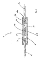
- Fig. 1 is a perspective view of a connector 1 according to the invention, formed by the connector 2, 3.
- the connector 2 is formed as a socket and the connector 3 as a plug. Since the connector 1 consists essentially of two corresponding connectors 2, 3, in the following the connector 2 (socket) is described as an embodiment of the invention.
- the connector (2) is formed from a housing (4) in which contacts (19) are arranged.
- the housing (4) is integrally formed from a socket body (6) a housing center body (4a) and a connection body (12), which are formed from any non-conductive insulating material.
- the socket body (6) has contact openings (8) which extend substantially as cylindrical passages through the entire connector housing (4) therethrough. In the present case two pairs spaced contact openings (8) in the connector (2) are formed, to which from the opposite side each electrical lines can be attached connected.
- On the housing center body (4a) by means of a connecting element (10) which is integrally connected to the housing (4), a lid (9) attached.
- the connecting element (10) is formed by means of film hinge (11a) on the housing center body (4).
- the lid is captively connected to the connector (2).
- the lid geometry and the receiving geometry of the lid (9) is adapted to the geometry of the socket body (6).
- the socket body (6) protrudes from the housing middle body (4a) as a plug contour out with a length which is geometrically designed so that the socket contacts therein (19) with the VDE-contact fingers are no longer touchable.
- the distance between the two domes (21a, 21b) is chosen geometrically such that the VDE test finger can not penetrate as far as the pin contact (20).
- connection body (12) integrally connects as part of the housing (4).
- the locking groove (22) is formed as a recess or as a groove in the housing (4).
- the task of the locking groove (22) is on the one hand the locking of the still to be described Gleit Whylementes (14) and at the same time Dicht.- and Fixiemut or receiving contour for the sealing contour (15) of the Gleit Whylementes (14).
- connection body (12) there are two screw terminals (13a, 13b), which are arranged accessible from the outside and protrude into the receiving space (23) of the connection body (12).
- the receiving space (23) is designed so that a conventional stripped cable at its end or a suitably prepared line can be accommodated therein. This can then be connected with conventional screwdriver on the female contact (19) or the connector (3) to the pin contacts (20) accordingly.
- a sliding, elastic sealing element (14) is used as the sliding sealing element (14), which has cable passages (18a, 18b) through which the cable to be connected passes, as in FIG Fig. 1 and Fig. 2 clearly visible.
- the cable passages (18a, 18b) are adapted to the line to be connected in accordance with their diameter and seal in consequence of the selection of the material of the Gleitêtlementes (14) radially on the line (24).
- flat cable can be used by accordingly the cable passages (18a, 18b) to be connected lines (24) or their outer contour are adjusted.
- the sliding seal element (14) has a sealing space (25), which is formed corresponding to the outer geometry of the connection body (12).
- the connection body (12) has an approximately cap-like construction in that the two passage openings or cable passages (18a, 18b) are located at the substantially closed end.
- the elastic sliding sealing element (14) is in a mounting position, which is accomplished by sliding the sliding sealing element against the direction of insertion, as it were, to the rear over the lines (24) to be mounted.
- the fitter can insert the cables into the recesses (23) of the optional socket contacts (19) or pin contacts (20). Since the sliding sealing element (14) has a sealing contour (15), which is arranged circumferentially at the inner opening end to the sealing space (25), after connecting the lines (24) to the screw connections (13a, 13b), the sliding sealing element can be placed over the outer contour of the Connection body (12) are pushed. When the sealing position is completely reached, the sealing contour (15) slides with its fixing lip (16) into the latching groove (22). It comes insofar to the radial sealing of the aforementioned screw terminals (13a, 13b) and the cable entries and recesses (23) of the connector (2, 3).
- the sliding sealing element (14) with its sealing space (25) is formed so that a displacement along the connecting body (12) is easily possible.
- a relatively soft, elastic material for the sealing contour (15) is used, so that this can dive easily with its fixing lip (16) in the locking groove (22).
- the sealing and insulation is based on the one hand in the area of the plug contour via a likewise attached sealing contour (15) and in the region of the connection body (12) exclusively upper the Gleitêtlement (14) in conjunction with the locking groove (22).
- a plurality of sealing lips in the region of the sliding sealing element (14) in the sealing space (25) may be arranged, which are spaced in pairs.
- a second sealing lip in the sealing space (25) could be arranged so that this water inlet between the cable and the cable passages (18a, 18b) which would enter into the gap towards the screw terminals (13a, 13b), keeps away from them ,
- first sliding sealing element (14) It could also be pushed beyond the first sliding sealing element (14) also a further second sliding seal, designed as a sliding element, so that substantially the entire connector would find space in a second surrounding sliding seal.
Landscapes
- Connector Housings Or Holding Contact Members (AREA)
- Details Of Connecting Devices For Male And Female Coupling (AREA)
Applications Claiming Priority (1)
| Application Number | Priority Date | Filing Date | Title |
|---|---|---|---|
| DE200810030737 DE102008030737B3 (de) | 2008-06-27 | 2008-06-27 | Zweipoliger Steckverbinder mit Gleitdichtelement |
Publications (1)
| Publication Number | Publication Date |
|---|---|
| EP2139077A1 true EP2139077A1 (fr) | 2009-12-30 |
Family
ID=40952000
Family Applications (1)
| Application Number | Title | Priority Date | Filing Date |
|---|---|---|---|
| EP09006654A Withdrawn EP2139077A1 (fr) | 2008-06-27 | 2009-05-18 | Connecteur à fiche bipolaire doté d'un élément d'étanchéité coulissant |
Country Status (2)
| Country | Link |
|---|---|
| EP (1) | EP2139077A1 (fr) |
| DE (1) | DE102008030737B3 (fr) |
Families Citing this family (6)
| Publication number | Priority date | Publication date | Assignee | Title |
|---|---|---|---|---|
| USD1108372S1 (en) | 2023-12-20 | 2026-01-06 | Molex, Llc | Connector |
| USD1099844S1 (en) | 2023-12-20 | 2025-10-28 | Molex, Llc | Socket connector |
| USD1100837S1 (en) | 2023-12-20 | 2025-11-04 | Molex, Llc | Connector |
| USD1102385S1 (en) | 2023-12-20 | 2025-11-18 | Molex, Llc | Connector |
| USD1107654S1 (en) | 2023-12-20 | 2025-12-30 | Molex, Llc | Connector |
| USD1100838S1 (en) | 2023-12-20 | 2025-11-04 | Molex, Llc | Connector |
Citations (8)
| Publication number | Priority date | Publication date | Assignee | Title |
|---|---|---|---|---|
| US3641478A (en) | 1969-07-03 | 1972-02-08 | Nottingham & Co Inc J B | Separable plug |
| US4443048A (en) * | 1981-10-02 | 1984-04-17 | Amp Incorporated | Assembly with verification feature |
| US4580863A (en) * | 1985-02-19 | 1986-04-08 | Amp Incorporated | Electrical contact socket which is manufactured with simplified tooling |
| US4772231A (en) * | 1986-11-07 | 1988-09-20 | Amp Incorporated | Unitary molded sealed connector with modular keying and terminal retention |
| US4857011A (en) * | 1988-02-08 | 1989-08-15 | Wyle Laboratories | Field repairable cable connector |
| US5720629A (en) * | 1996-10-16 | 1998-02-24 | The Whitaker Corporation | Sealed electrical connector |
| US7044762B1 (en) * | 2005-06-01 | 2006-05-16 | Mea Technologies Pte. Ltd. | Waterproof connector |
| DE102005016266A1 (de) | 2005-04-08 | 2006-10-12 | Amphenol-Tuchel Electronics Gmbh | Berührungssichere Steckverbindung, insbesondere Solarsteckverbindung |
Family Cites Families (2)
| Publication number | Priority date | Publication date | Assignee | Title |
|---|---|---|---|---|
| US5863221A (en) * | 1997-07-23 | 1999-01-26 | Leviton Manufacturing Co., Inc. | Insulating enclosure to provide a water-tight seal with an electric connector |
| DE102004027255A1 (de) * | 2004-06-03 | 2005-12-22 | Yukita Electric Wire Co., Ltd. | Wasserdichter Steckverbinder |
-
2008
- 2008-06-27 DE DE200810030737 patent/DE102008030737B3/de not_active Expired - Fee Related
-
2009
- 2009-05-18 EP EP09006654A patent/EP2139077A1/fr not_active Withdrawn
Patent Citations (8)
| Publication number | Priority date | Publication date | Assignee | Title |
|---|---|---|---|---|
| US3641478A (en) | 1969-07-03 | 1972-02-08 | Nottingham & Co Inc J B | Separable plug |
| US4443048A (en) * | 1981-10-02 | 1984-04-17 | Amp Incorporated | Assembly with verification feature |
| US4580863A (en) * | 1985-02-19 | 1986-04-08 | Amp Incorporated | Electrical contact socket which is manufactured with simplified tooling |
| US4772231A (en) * | 1986-11-07 | 1988-09-20 | Amp Incorporated | Unitary molded sealed connector with modular keying and terminal retention |
| US4857011A (en) * | 1988-02-08 | 1989-08-15 | Wyle Laboratories | Field repairable cable connector |
| US5720629A (en) * | 1996-10-16 | 1998-02-24 | The Whitaker Corporation | Sealed electrical connector |
| DE102005016266A1 (de) | 2005-04-08 | 2006-10-12 | Amphenol-Tuchel Electronics Gmbh | Berührungssichere Steckverbindung, insbesondere Solarsteckverbindung |
| US7044762B1 (en) * | 2005-06-01 | 2006-05-16 | Mea Technologies Pte. Ltd. | Waterproof connector |
Also Published As
| Publication number | Publication date |
|---|---|
| DE102008030737B3 (de) | 2010-03-04 |
Similar Documents
| Publication | Publication Date | Title |
|---|---|---|
| EP1926179B1 (fr) | Connecteur à fiches pour conducteurs électriques assemblés | |
| DE102010002176B4 (de) | Kontakteinrichtung | |
| DE102012024588B4 (de) | Steckverbinder | |
| DE102012111646B4 (de) | Isolierkörper mit integriertem Schirmelement | |
| DE202017101060U1 (de) | Steckverbinder, insbesondere für eine Hochstromanwendung | |
| DE102013213336A1 (de) | Elektrischer steckverbinder und steckverbindersystem für ein elektro- oder hybridfahrzeug | |
| DE102009043516A1 (de) | Zweiteiliges Kontaktelement für Hochspannungssteckverbinder | |
| DE102008006340A1 (de) | Steckverbindungsanordnung mit aufgeformtem abgeschirmtem Gehäuse | |
| DE102008030737B3 (de) | Zweipoliger Steckverbinder mit Gleitdichtelement | |
| DE102009016157A1 (de) | Abgeschirmte Steckverbinderanordnung | |
| DE102008045801A1 (de) | Photovoltaik-Steckverbindung | |
| DE202012001638U1 (de) | Gehäuse für eine Kontakteinrichtung | |
| EP3895256A1 (fr) | Connecteur enfichable rond présentant un dispositif de verrouillage | |
| DE102010022690A1 (de) | Elektrischer Steckverbinder mit PE-Kontakt | |
| DE112017005162B4 (de) | Durchgangsverbinderanordnung | |
| DE102017200741B4 (de) | Rundsteckverbinder zur elektrischen Verbindung und mechanischen Verriegelung mit einem Standardgegenstück | |
| DE202013000969U1 (de) | Steckverbinder | |
| WO2023186209A1 (fr) | Module de mise à la terre destiné à être reçu dans un cadre modulaire de connecteur à fiche métallique et qui met à la terre ledit cadre modulaire | |
| EP3477777B1 (fr) | Ligne électrique pourvue d'un terminal de blindage | |
| EP3364504B1 (fr) | Connecteur à fiche cylindrique | |
| DE102009038092B3 (de) | Buchsenkontaktelement | |
| DE112012003582T5 (de) | Verbinder und Bedeckungselement für diesen | |
| DE102008059000A1 (de) | Elektrischer Steckverbinder | |
| EP4122056B1 (fr) | Module de fiche de connexion blindé | |
| EP2913898B1 (fr) | Connecteur à fiches électrique et son procédé de montage |
Legal Events
| Date | Code | Title | Description |
|---|---|---|---|
| PUAI | Public reference made under article 153(3) epc to a published international application that has entered the european phase |
Free format text: ORIGINAL CODE: 0009012 |
|
| AK | Designated contracting states |
Kind code of ref document: A1 Designated state(s): AT BE BG CH CY CZ DE DK EE ES FI FR GB GR HR HU IE IS IT LI LT LU LV MC MK MT NL NO PL PT RO SE SI SK TR |
|
| 17P | Request for examination filed |
Effective date: 20100630 |
|
| 17Q | First examination report despatched |
Effective date: 20100726 |
|
| STAA | Information on the status of an ep patent application or granted ep patent |
Free format text: STATUS: THE APPLICATION HAS BEEN WITHDRAWN |
|
| 18W | Application withdrawn |
Effective date: 20130828 |