EP2139077A1 - Bipolar connector with slide sealing element - Google Patents
Bipolar connector with slide sealing element Download PDFInfo
- Publication number
- EP2139077A1 EP2139077A1 EP09006654A EP09006654A EP2139077A1 EP 2139077 A1 EP2139077 A1 EP 2139077A1 EP 09006654 A EP09006654 A EP 09006654A EP 09006654 A EP09006654 A EP 09006654A EP 2139077 A1 EP2139077 A1 EP 2139077A1
- Authority
- EP
- European Patent Office
- Prior art keywords
- connector
- sealing
- sliding
- sealing element
- housing
- Prior art date
- Legal status (The legal status is an assumption and is not a legal conclusion. Google has not performed a legal analysis and makes no representation as to the accuracy of the status listed.)
- Withdrawn
Links
- 238000007789 sealing Methods 0.000 title claims abstract description 53
- 238000010276 construction Methods 0.000 description 2
- 238000009434 installation Methods 0.000 description 2
- 230000001419 dependent effect Effects 0.000 description 1
- 238000006073 displacement reaction Methods 0.000 description 1
- 239000013013 elastic material Substances 0.000 description 1
- 238000005538 encapsulation Methods 0.000 description 1
- 238000003780 insertion Methods 0.000 description 1
- 230000037431 insertion Effects 0.000 description 1
- 239000011810 insulating material Substances 0.000 description 1
- 238000009413 insulation Methods 0.000 description 1
- 238000004519 manufacturing process Methods 0.000 description 1
- 239000000463 material Substances 0.000 description 1
- 238000000034 method Methods 0.000 description 1
- 230000035515 penetration Effects 0.000 description 1
- XLYOFNOQVPJJNP-UHFFFAOYSA-N water Substances O XLYOFNOQVPJJNP-UHFFFAOYSA-N 0.000 description 1
Images


Classifications
-
- H—ELECTRICITY
- H01—ELECTRIC ELEMENTS
- H01R—ELECTRICALLY-CONDUCTIVE CONNECTIONS; STRUCTURAL ASSOCIATIONS OF A PLURALITY OF MUTUALLY-INSULATED ELECTRICAL CONNECTING ELEMENTS; COUPLING DEVICES; CURRENT COLLECTORS
- H01R13/00—Details of coupling devices of the kinds covered by groups H01R12/70 or H01R24/00 - H01R33/00
- H01R13/46—Bases; Cases
- H01R13/52—Dustproof, splashproof, drip-proof, waterproof, or flameproof cases
- H01R13/5205—Sealing means between cable and housing, e.g. grommet
- H01R13/5208—Sealing means between cable and housing, e.g. grommet having at least two cable receiving openings
-
- H—ELECTRICITY
- H01—ELECTRIC ELEMENTS
- H01R—ELECTRICALLY-CONDUCTIVE CONNECTIONS; STRUCTURAL ASSOCIATIONS OF A PLURALITY OF MUTUALLY-INSULATED ELECTRICAL CONNECTING ELEMENTS; COUPLING DEVICES; CURRENT COLLECTORS
- H01R13/00—Details of coupling devices of the kinds covered by groups H01R12/70 or H01R24/00 - H01R33/00
- H01R13/46—Bases; Cases
- H01R13/52—Dustproof, splashproof, drip-proof, waterproof, or flameproof cases
- H01R13/5219—Sealing means between coupling parts, e.g. interfacial seal
Definitions
- the invention relates to a connector consisting of two connectors, of which preferably the first is a plug-side connector (plug) and the second connector is preferably called a jack-side connector (socket), according to the preamble of claim 1.
- plug plug-side connector
- jack jack-side connector
- the connector according to the invention is particularly suitable for use in photovoltaic systems.
- the plug has a contact body with contact pins in the respective socket body or pen body.
- connectors are regularly under electrical load or under electrical voltage. It is therefore usually difficult and dangerous for a fitter or for persons who typically maintain the system to replace or install such connectors.
- a special claim on the safety of such connectors is given by a VDE requirement, namely the finger safety, which is checked with the VDE test finger. When touching the connector in the area of the contacts, the VDE test finger must not touch it in an electrically conductive manner. It is therefore necessary to choose a design that meets this requirement.
- the contact pins with the length L reach to the front end of the plug, they can be touched very easily, if due to the size of the socket with a length Lb and a diameter Db the opening diameter Ds is then so large and the aforementioned VDE Test finger can come into contact with the tip of the contact pin.
- the contact pin is to have the length Ls of the socket length Lb, contact with the VDE test fingers can only be prevented when the enclosing Plug body or contact body is constructed longer, namely greater than Ls plus the penetration depth of the test finger.
- the contact pin could also be chosen shorter, so that it lies with its reachable end deep enough in the contact body; but then the effective contact surface would be reduced and this is to avoid it.
- the invention is therefore based on the task of creating a finger-proof and sealed connector, which on the one hand on site or on site can be assembled, with conventional tools without the use of special tools, while requesting the tightness of the connector, which without much effort in plugged and unplugged state is to be produced.
- Fig. 1 is a perspective view of a connector 1 according to the invention, formed by the connector 2, 3.
- the connector 2 is formed as a socket and the connector 3 as a plug. Since the connector 1 consists essentially of two corresponding connectors 2, 3, in the following the connector 2 (socket) is described as an embodiment of the invention.
- the connector (2) is formed from a housing (4) in which contacts (19) are arranged.
- the housing (4) is integrally formed from a socket body (6) a housing center body (4a) and a connection body (12), which are formed from any non-conductive insulating material.
- the socket body (6) has contact openings (8) which extend substantially as cylindrical passages through the entire connector housing (4) therethrough. In the present case two pairs spaced contact openings (8) in the connector (2) are formed, to which from the opposite side each electrical lines can be attached connected.
- On the housing center body (4a) by means of a connecting element (10) which is integrally connected to the housing (4), a lid (9) attached.
- the connecting element (10) is formed by means of film hinge (11a) on the housing center body (4).
- the lid is captively connected to the connector (2).
- the lid geometry and the receiving geometry of the lid (9) is adapted to the geometry of the socket body (6).
- the socket body (6) protrudes from the housing middle body (4a) as a plug contour out with a length which is geometrically designed so that the socket contacts therein (19) with the VDE-contact fingers are no longer touchable.
- the distance between the two domes (21a, 21b) is chosen geometrically such that the VDE test finger can not penetrate as far as the pin contact (20).
- connection body (12) integrally connects as part of the housing (4).
- the locking groove (22) is formed as a recess or as a groove in the housing (4).
- the task of the locking groove (22) is on the one hand the locking of the still to be described Gleit Whylementes (14) and at the same time Dicht.- and Fixiemut or receiving contour for the sealing contour (15) of the Gleit Whylementes (14).
- connection body (12) there are two screw terminals (13a, 13b), which are arranged accessible from the outside and protrude into the receiving space (23) of the connection body (12).
- the receiving space (23) is designed so that a conventional stripped cable at its end or a suitably prepared line can be accommodated therein. This can then be connected with conventional screwdriver on the female contact (19) or the connector (3) to the pin contacts (20) accordingly.
- a sliding, elastic sealing element (14) is used as the sliding sealing element (14), which has cable passages (18a, 18b) through which the cable to be connected passes, as in FIG Fig. 1 and Fig. 2 clearly visible.
- the cable passages (18a, 18b) are adapted to the line to be connected in accordance with their diameter and seal in consequence of the selection of the material of the Gleitêtlementes (14) radially on the line (24).
- flat cable can be used by accordingly the cable passages (18a, 18b) to be connected lines (24) or their outer contour are adjusted.
- the sliding seal element (14) has a sealing space (25), which is formed corresponding to the outer geometry of the connection body (12).
- the connection body (12) has an approximately cap-like construction in that the two passage openings or cable passages (18a, 18b) are located at the substantially closed end.
- the elastic sliding sealing element (14) is in a mounting position, which is accomplished by sliding the sliding sealing element against the direction of insertion, as it were, to the rear over the lines (24) to be mounted.
- the fitter can insert the cables into the recesses (23) of the optional socket contacts (19) or pin contacts (20). Since the sliding sealing element (14) has a sealing contour (15), which is arranged circumferentially at the inner opening end to the sealing space (25), after connecting the lines (24) to the screw connections (13a, 13b), the sliding sealing element can be placed over the outer contour of the Connection body (12) are pushed. When the sealing position is completely reached, the sealing contour (15) slides with its fixing lip (16) into the latching groove (22). It comes insofar to the radial sealing of the aforementioned screw terminals (13a, 13b) and the cable entries and recesses (23) of the connector (2, 3).
- the sliding sealing element (14) with its sealing space (25) is formed so that a displacement along the connecting body (12) is easily possible.
- a relatively soft, elastic material for the sealing contour (15) is used, so that this can dive easily with its fixing lip (16) in the locking groove (22).
- the sealing and insulation is based on the one hand in the area of the plug contour via a likewise attached sealing contour (15) and in the region of the connection body (12) exclusively upper the Gleitêtlement (14) in conjunction with the locking groove (22).
- a plurality of sealing lips in the region of the sliding sealing element (14) in the sealing space (25) may be arranged, which are spaced in pairs.
- a second sealing lip in the sealing space (25) could be arranged so that this water inlet between the cable and the cable passages (18a, 18b) which would enter into the gap towards the screw terminals (13a, 13b), keeps away from them ,
- first sliding sealing element (14) It could also be pushed beyond the first sliding sealing element (14) also a further second sliding seal, designed as a sliding element, so that substantially the entire connector would find space in a second surrounding sliding seal.
Landscapes
- Connector Housings Or Holding Contact Members (AREA)
- Details Of Connecting Devices For Male And Female Coupling (AREA)
Abstract
Description
Die Erfindung bezieht sich auf eine Steckverbindung bestehend aus zwei Steckverbindern, wovon vorzugsweise der erste ein steckerseitiger Steckverbinder (Stecker) darstellt und der zweite Steckverbinder vorzugsweise einen buchsenseitiger Steckverbinder (Buchse) genannt ist, gemäß dem Oberbegriff von Anspruch 1.The invention relates to a connector consisting of two connectors, of which preferably the first is a plug-side connector (plug) and the second connector is preferably called a jack-side connector (socket), according to the preamble of claim 1.
Die erfindungsgemäße Steckverbindung ist insbesondere geeignet zum Einsatz in Fotovoltaiksystemen. Der Stecker weist einen Kontaktkörper mit Kontaktstiften in dem jeweiligen Buchsenkörper oder Stiftkörper auf. Insbesondere im Bereich der Fotovoltaik stehen die an eine Fotovoltaikanlage oder an eine entsprechende Einrichtung angeschlossene Steckverbinder regelmäßig unter elektrischer Last beziehungsweise unter elektrischer Spannung. Es ist daher für einen Monteur oder für Personen, welche die Anlage typischerweise warten in der Regel schwierig und gefährlich solche Steckverbinder auszutauschen oder einzubauen. Ein besonderer Anspruch an die Sicherheit solcher Steckverbinder wird durch eine VDE-Anforderung gegeben, nämlich der Fingersicherheit, welche geprüft wird mit dem VDE-Prüffinger. Dabei darf der VDE-Prüffinger bei Berühren des Steckverbinders im Bereich der Kontakte diese nicht elektrisch leitend berühren. Es ist daher notwendig, eine Konstruktion so zu wählen, dass dieses Erfordernis erfüllt ist.The connector according to the invention is particularly suitable for use in photovoltaic systems. The plug has a contact body with contact pins in the respective socket body or pen body. In particular, in the field of photovoltaic connected to a photovoltaic system or to a corresponding device connectors are regularly under electrical load or under electrical voltage. It is therefore usually difficult and dangerous for a fitter or for persons who typically maintain the system to replace or install such connectors. A special claim on the safety of such connectors is given by a VDE requirement, namely the finger safety, which is checked with the VDE test finger. When touching the connector in the area of the contacts, the VDE test finger must not touch it in an electrically conductive manner. It is therefore necessary to choose a design that meets this requirement.
Im Stand der Technik ist beispielsweise die
Wenn die Kontaktstifte mit der Länge L bis zum vorderen Ende des Steckers reichen, können diese sehr leicht berührt werden, wenn bedingt durch die Abmessung der Buchse mit einer Länge Lb und einem Durchmesser Db der Öffnungsdurchmesser Ds dann so groß ist und der zuvor genannte VDE-Prüffinger in Kontakt mit der Spitze des Kontaktstiftes treten kann. Wenn allerdings der Kontaktstift die Länge Ls der Buchsenlänge Lb haben soll, kann ein Kontakt mit den VDE-Prüffingem nur verhindert werden, wenn der umschließende Steckerkörper beziehungsweise Kontaktkörper länger konstruiert wird, nämlich größer als Ls plus die Eindringtiefe des Prüffingers. Alternativ könnte zwar der Kontaktstift auch kürzer gewählt werden, so dass er mit seinem berührbaren Ende tief genug im Kontaktkörper liegt; dann wäre aber die effektive Kontaktanlagefläche vermindert und dies gllt es zu vermeiden.If the contact pins with the length L reach to the front end of the plug, they can be touched very easily, if due to the size of the socket with a length Lb and a diameter Db the opening diameter Ds is then so large and the aforementioned VDE Test finger can come into contact with the tip of the contact pin. However, if the contact pin is to have the length Ls of the socket length Lb, contact with the VDE test fingers can only be prevented when the enclosing Plug body or contact body is constructed longer, namely greater than Ls plus the penetration depth of the test finger. Alternatively, although the contact pin could also be chosen shorter, so that it lies with its reachable end deep enough in the contact body; but then the effective contact surface would be reduced and this is to avoid it.
Ein weiterer Nachteil gattungsgemäßer Steckverbinder liegt darin, dass diese entweder vom Monteur am Montageort an ein elektrisches Kabel der Fotovoltaikanlage anzuschleißen sind oder aber dass der Steckverbinder mit bereits angeschlossenen Kabeln in der Regel umspritzten Kabeln am Kabelende an der Montageanlage oder an der Fotovoltaikanlage zu montieren ist. In beiden Fällen bedingt dies eine relativ große Bauartkonstruktion und bei Verwendung von Crimpkontakten darüber hinaus Spezialwerkzeuge, Sofern auf eine Anschlusstechnik wie die der Schraubverbindung zurück gegriffen wird, besteht der technische Nachteil darin, dass die Schraubverbindung gegenüber der Umgebung abgedichtet werden muss, was insbesondere Probleme bei der Handhabung und bei der Reproduzierbarkeit von dichten Steckverbindungen mit sich bringt. Eine alternative Ausführungsform dahingegen ist die Montage werkseitig mit Umspritzung der Schraubanschlüsse, so dass diese dicht gegenüber der Umgebung ausgebildet sind. Nachteilig ist dabei, dass beim Auswechseln des Steckverbinders in der Regel das gesamte Kabel mit ausgewechselt werden muss.Another disadvantage of generic connectors is that they are to be attached either by the fitter at the installation site to an electrical cable of the photovoltaic system or that the connector with already connected cables usually overmolded cables at the cable end to the mounting system or to the photovoltaic system is to be mounted. In both cases, this requires a relatively large construction design and when using crimp contacts beyond special tools, If a connection technique such as the screw is used back, the technical disadvantage is that the screw must be sealed against the environment, which in particular problems with the handling and the reproducibility of tight connectors with it brings. An alternative embodiment, however, is the factory assembly with encapsulation of the screw, so that they are formed close to the environment. The disadvantage here is that when replacing the connector usually the entire cable must be replaced with.
Die Erfindung hat sich daher die Aufgabe gestellt, einen fingersicheren und dichten Steckverbinder zu schaffen, welcher einerseits auf der Baustelle oder vor Ort konfektionierbar ist, mit herkömmlichem Werkzeug ohne Verwendung von Spezialwerkzeug, bei gleichzeitiger Anforderung an die Dichtheit des Steckverbinders, die ohne viel Aufwand im gesteckten und ungesteckten Zustand hergestellt werden soll.The invention is therefore based on the task of creating a finger-proof and sealed connector, which on the one hand on site or on site can be assembled, with conventional tools without the use of special tools, while requesting the tightness of the connector, which without much effort in plugged and unplugged state is to be produced.
Erfindungsgemäß geschieht dies durch die in dem Anspruch 1 angegebenen Merkmale. Bevorzugte Ausgestaltungen ergeben sich aus den Unteransprüchen. Weitere Vorteile, Ziele und Einzelheiten der Erfindung seien im Folgenden an Hand der Zeichnung beschrieben. In den Zeichnungen zeigt:
-
Fig. 1 eine schematische, dreidimensionale Ansicht der erfindungsgemäßen Steckverbindung aus zwei Steckverbindern; -
Fig. 2 die zuFig. 1 perspektivisch gespiegelte Ansicht der Steckverbindung von unten; -
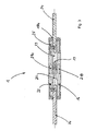
Fig. 3 zeigt einen Schnitt durch die Steckverbindung gemäßFig. 1 im gesteckten Zustand.
-
Fig. 1 a schematic, three-dimensional view of the connector according to the invention of two connectors; -
Fig. 2 the tooFig. 1 perspective mirrored view of the connector from below; -
Fig. 3 shows a section through the connector according toFig. 1 in mated condition.
Im Folgenden wird die
Der Steckverbinder (2) ist gebildet aus einem Gehäuse (4) in welchem Kontakte (19) angeordnet sind. Das Gehäuse (4) ist einstückig gebildet aus einem Buchsenkörper (6) einem Gehäusemittelkörper (4a) und einem Anschlusskörper (12), welche aus einem beliebigen, nicht leitenden Isolierstoff gebildet sind. Der Buchsenkörper (6) verfügt über Kontaktöffnungen (8) die im wesentlichen als zylinderförmige Durchgänge durch das gesamte Steckverbindergehäuse (4) hindurch reichen. Im vorliegenden Falle sind zwei paarweise beabstandete Kontaktöffnungen (8) in dem Steckverbinder (2) ausgebildet, an welche von der gegenüberliegenden Seite jeweils elektrische Leitungen anschließbar angebracht werden können. Am Gehäusemittelkörper (4a) ist mittels eines Verbindungselementes (10), welches einstückig mit dem Gehäuse (4) verbunden ist, ein Deckel (9) angebracht. Das Verbindungselement (10) ist mittels Filmscharnier (11a) am Gehäusemittelkörper (4) angeformt. Hierdurch wird der Deckel unverlierbar mit dem Steckverbinder (2) verbunden. Die Deckelgeometrie und die Aufnahmegeometrie des Deckels (9) ist auf die Geometrie des Buchsenkörpers (6) angepasst. Der Buchsenkörper (6) ragt aus dem Gehäusemittelkörper (4a) als Steckkontur heraus mit einer Länge, die so geometrisch ausgebildet ist, dass die darin befindlichen Buchsenkontakte (19) mit den VDE-Berührfingern nicht mehr berührbar sind.The connector (2) is formed from a housing (4) in which contacts (19) are arranged. The housing (4) is integrally formed from a socket body (6) a housing center body (4a) and a connection body (12), which are formed from any non-conductive insulating material. The socket body (6) has contact openings (8) which extend substantially as cylindrical passages through the entire connector housing (4) therethrough. In the present case two pairs spaced contact openings (8) in the connector (2) are formed, to which from the opposite side each electrical lines can be attached connected. On the housing center body (4a) by means of a connecting element (10) which is integrally connected to the housing (4), a lid (9) attached. The connecting element (10) is formed by means of film hinge (11a) on the housing center body (4). As a result, the lid is captively connected to the connector (2). The lid geometry and the receiving geometry of the lid (9) is adapted to the geometry of the socket body (6). The socket body (6) protrudes from the housing middle body (4a) as a plug contour out with a length which is geometrically designed so that the socket contacts therein (19) with the VDE-contact fingers are no longer touchable.
Analog gilt für den Stecker (3), dass dort entsprechend korrespondierende Dome, die Stiftkontakte (20), gegenüber dem VDE-Prüffinger sichem, wie dies aus
Allerdings ersichtlich ist, dass der Abstand zwischen den beiden Domen (21a, 21b) so geometrisch gewählt ist, dass der VDE-Prüffinger nicht bis zum Stiftkontakt (20) vordringen kann.However, it can be seen that the distance between the two domes (21a, 21b) is chosen geometrically such that the VDE test finger can not penetrate as far as the pin contact (20).
Auf der dem Stiftkörper (6) gegenüberliegende Seite des Gehäusemittelkörpers (4a) schließt sich der Anschlusskörper (12) einstückig an als Teil des Gehäuses (4). Zwischen dem Gehäusemittelkörper (4a) und dem Anschlusskörper (12) befindet sich eine umlaufende Rastnut (22). Die Rastnut (22) ist als Vertiefung beziehungsweise als Rinne im Gehäuse (4) eingeformt.On the pin body (6) opposite side of the housing center body (4a), the connection body (12) integrally connects as part of the housing (4). Between the housing center body (4a) and the connecting body (12) is a circumferential locking groove (22). The locking groove (22) is formed as a recess or as a groove in the housing (4).
Aufgabe der Rastnut (22) ist einerseits das Verrasten des noch zu beschreibenden Gleitdichtelementes (14) und gleichzeitig Dicht.- und Fixiemut beziehungsweise Aufnahmekontur für die Dichtkontur (15) des Gleitdichtelementes (14). Im Anschlusskörper (12) befinden sich zwei Schraubanschlüsse (13a, 13b), welche von außen zugänglich angeordnet sind und in dem Aufnahmeraum (23) des Anschlusskörpers (12) hineinragen. Der Aufnahmeraum (23) ist so ausgebildet, dass darin ein herkömmliches an seinem Ende abisoliertes Kabel beziehungsweise eine entsprechend vorbereitete Leitung aufgenommen werden kann.
Diese kann dann mit herkömmlicher Schraubendreher am Buchsenkontakt (19) beziehungsweise beim Steckverbinder (3) an den Stiftkontakten (20) entsprechend angeschlossen werden.The task of the locking groove (22) is on the one hand the locking of the still to be described Gleitdichtelementes (14) and at the same time Dicht.- and Fixiemut or receiving contour for the sealing contour (15) of the Gleitdichtelementes (14). In the connection body (12) there are two screw terminals (13a, 13b), which are arranged accessible from the outside and protrude into the receiving space (23) of the connection body (12). The receiving space (23) is designed so that a conventional stripped cable at its end or a suitably prepared line can be accommodated therein.
This can then be connected with conventional screwdriver on the female contact (19) or the connector (3) to the pin contacts (20) accordingly.
Erfindungsgemäß wird als Gleitdichtelement (14) ein verschiebbares, elastisches Dichtelement (14) verwendet, welches über Kabeldurchgänge (18a, 18b) verfügt, durch die das anzuschließende Kabel hindurch läuft, wie in
Die Kabeldurchgänge (18a, 18b) sind auf die anzuschließende Leitung in ihrem Durchmesser entsprechend anzupassen und dichten in folge der Auswahl des Materials des Gleitdichtelementes (14) radial an der Leitung (24) ab. Durch die entsprechende Variabilität und damit mögliche Auswahl unterschiedlicher Kabelquerschnitte können auch unrunde Kabelformen, insbesondere Flachkabel Verwendung finden, indem entsprechend die Kabeldurchgänge (18a, 18b) den anzuschließenden Leitungen (24) beziehungsweise deren Außenkontur angepasst werden. Das Gleitdichtelement (14) verfügt über einen Dichtraum (25), welcher korrespondierend zur Außengeometrie des Anschlusskörpers (12) ausgebildet ist. Insofern hat der Anschlusskörper (12) eine in etwa kappenartiger Aufbau, indem sich an dem im wesentlichen geschlossenen Ende die beiden Durchtrittsöffnungen beziehungsweise Kabeldurchgänge (18a, 18b) befinden.According to the invention, a sliding, elastic sealing element (14) is used as the sliding sealing element (14), which has cable passages (18a, 18b) through which the cable to be connected passes, as in FIG
The cable passages (18a, 18b) are adapted to the line to be connected in accordance with their diameter and seal in consequence of the selection of the material of the Gleitdichtelementes (14) radially on the line (24). By the corresponding variability and thus possible selection of different cable cross-sections and non-circular cable shapes, in particular flat cable can be used by accordingly the cable passages (18a, 18b) to be connected lines (24) or their outer contour are adjusted. The sliding seal element (14) has a sealing space (25), which is formed corresponding to the outer geometry of the connection body (12). In this respect, the connection body (12) has an approximately cap-like construction in that the two passage openings or cable passages (18a, 18b) are located at the substantially closed end.
Zur Montage befindet sich das elastische Gleitdichtelement (14) in einer Montageposition, welche dadurch bewerkstelligt wird, dass das Gleitdichtelement entgegen der Steckrichtung sozusagen nach hinten über die zu montierenden Leitungen (24) geschoben wird.
In einem nächsten Arbeitsschritt kann der Monteur die Kabel in die Aufnehmungen (23) der wahlweise Buchsenkontakte (19) oder Stiftkontakte (20) einführen. Da das Gleitdichtelement (14) über eine Dichtkontur (15), welche umlaufend am inneren Öffnungsende zum Dichtraum (25) angeordnet ist, verfügt, kann nach Anschluss der Leitungen (24) an den Schraubanschlüssen (13a, 13b) das Gleitdichtelement über die Außenkontur des Anschlusskörpers (12) geschoben werden. Bei vollständigem Erreichen der Dichtstellung gleitet die Dichtkontur (15) mit ihrer Fixierungslippe (16) in die Rastnut (22). Es kommt insofern zur radialen Abdichtung der zuvor genannten Schraubanschlüsse (13a, 13b) sowie der Kabeleinführungen und Aufnehmungen (23) des Steckverbinders (2, 3).For installation, the elastic sliding sealing element (14) is in a mounting position, which is accomplished by sliding the sliding sealing element against the direction of insertion, as it were, to the rear over the lines (24) to be mounted.
In a next step, the fitter can insert the cables into the recesses (23) of the optional socket contacts (19) or pin contacts (20). Since the sliding sealing element (14) has a sealing contour (15), which is arranged circumferentially at the inner opening end to the sealing space (25), after connecting the lines (24) to the screw connections (13a, 13b), the sliding sealing element can be placed over the outer contour of the Connection body (12) are pushed. When the sealing position is completely reached, the sealing contour (15) slides with its fixing lip (16) into the latching groove (22). It comes insofar to the radial sealing of the aforementioned screw terminals (13a, 13b) and the cable entries and recesses (23) of the connector (2, 3).
Vorzugsweise wird das Gleitdichtelement (14) mit seinem Dichtraum (25) so ausgebildet, dass ein Verschieben entlang des Anschlusskörpers (12) problemlos möglich ist. Insbesondere wird hierzu ein relativ weiches, elastisches Material für die Dichtkontur (15) verwendet, so dass dieses mit seiner Fixierungslippe (16) problemlos in die Rastnut (22) eintauchen kann. Wie in
Das hier gezeigte Ausführungsbeispiel der Erfindung ist nur exemplarisch und nicht durch seine geometrische Anordnung eingeschränkt. So können beispielsweise auch mehrere Dichtlippen im Bereich des Gleitdichtelementes (14) im Dichtraum (25) angeordnet sein, welche paarweise beabstandet sind. So könnte beispielsweise zusätzlich eine zweite Dichtlippe im Dichtraum (25) so angeordnet sein, dass diese Wassereintritt zwischen dem Kabel und den Kabeldurchgängen (18a, 18b) welcher in den Zwischenraum hin zu den Schraubanschlüssen (13a, 13b) eintreten würde, von diesen fern hält.The embodiment of the invention shown here is only exemplary and not limited by its geometric arrangement. Thus, for example, a plurality of sealing lips in the region of the sliding sealing element (14) in the sealing space (25) may be arranged, which are spaced in pairs. For example, in addition, a second sealing lip in the sealing space (25) could be arranged so that this water inlet between the cable and the cable passages (18a, 18b) which would enter into the gap towards the screw terminals (13a, 13b), keeps away from them ,
Es könnte darüber hinaus auch eine weitere zweite Gleitdichtung, ausgebildet als Gleitelement über das erste Gleitdichtelement (14) hinaus geschoben werden, so dass im wesentlichen der gesamte Steckverbinder in einer zweiten umgebenden Gleitdichtung Platz finden würde.It could also be pushed beyond the first sliding sealing element (14) also a further second sliding seal, designed as a sliding element, so that substantially the entire connector would find space in a second surrounding sliding seal.
- 11
- Steckverbindungconnector
- 2, 32, 3
- SteckverbinderConnectors
- 44
- Gehäusecasing
- 4a4a
- GehäusemittelkörperHousing central body
- 55
- KontaktkörperContact body
- 66
- Stiftkörperpen body
- 77
- Buchsenkörperbush body
- 88th
- Kontaktöffnungencontact openings
- 99
- Deckelcover
- 1010
- Verbindungselementconnecting element
- 11a, 11b11a, 11b
- Filmscharnierfilm hinge
- 1212
- Anschlusskörperconnection body
- 13a, 13b13a, 13b
- Schraubanschlüssescrew
- 1414
- Gleitdichtelementfloating seal
- 1515
- Dichtkontur (umlaufend)Sealing contour (circumferential)
- 1616
- Fixierungslippefixing lip
- 18a, 18b18a, 18b
- KabeldurchgängeFairleads
- 1919
- Buchsenkontaktefemale contacts
- 2020
- Stiftkontaktepin contacts
- 21a, 21b21a, 21b
- DomeDome
- 2222
- Rastnutlocking groove
- 2323
- AufnahmenRecordings
- 2424
- Leitungencables
- 2525
- Dichtraumtight space
Claims (11)
Applications Claiming Priority (1)
| Application Number | Priority Date | Filing Date | Title |
|---|---|---|---|
| DE200810030737 DE102008030737B3 (en) | 2008-06-27 | 2008-06-27 | Two-pole connector with sliding sealing element |
Publications (1)
| Publication Number | Publication Date |
|---|---|
| EP2139077A1 true EP2139077A1 (en) | 2009-12-30 |
Family
ID=40952000
Family Applications (1)
| Application Number | Title | Priority Date | Filing Date |
|---|---|---|---|
| EP09006654A Withdrawn EP2139077A1 (en) | 2008-06-27 | 2009-05-18 | Bipolar connector with slide sealing element |
Country Status (2)
| Country | Link |
|---|---|
| EP (1) | EP2139077A1 (en) |
| DE (1) | DE102008030737B3 (en) |
Families Citing this family (6)
| Publication number | Priority date | Publication date | Assignee | Title |
|---|---|---|---|---|
| USD1100837S1 (en) | 2023-12-20 | 2025-11-04 | Molex, Llc | Connector |
| USD1102385S1 (en) | 2023-12-20 | 2025-11-18 | Molex, Llc | Connector |
| USD1099844S1 (en) | 2023-12-20 | 2025-10-28 | Molex, Llc | Socket connector |
| USD1108372S1 (en) | 2023-12-20 | 2026-01-06 | Molex, Llc | Connector |
| USD1100838S1 (en) | 2023-12-20 | 2025-11-04 | Molex, Llc | Connector |
| USD1107654S1 (en) | 2023-12-20 | 2025-12-30 | Molex, Llc | Connector |
Citations (8)
| Publication number | Priority date | Publication date | Assignee | Title |
|---|---|---|---|---|
| US3641478A (en) | 1969-07-03 | 1972-02-08 | Nottingham & Co Inc J B | Separable plug |
| US4443048A (en) * | 1981-10-02 | 1984-04-17 | Amp Incorporated | Assembly with verification feature |
| US4580863A (en) * | 1985-02-19 | 1986-04-08 | Amp Incorporated | Electrical contact socket which is manufactured with simplified tooling |
| US4772231A (en) * | 1986-11-07 | 1988-09-20 | Amp Incorporated | Unitary molded sealed connector with modular keying and terminal retention |
| US4857011A (en) * | 1988-02-08 | 1989-08-15 | Wyle Laboratories | Field repairable cable connector |
| US5720629A (en) * | 1996-10-16 | 1998-02-24 | The Whitaker Corporation | Sealed electrical connector |
| US7044762B1 (en) * | 2005-06-01 | 2006-05-16 | Mea Technologies Pte. Ltd. | Waterproof connector |
| DE102005016266A1 (en) | 2005-04-08 | 2006-10-12 | Amphenol-Tuchel Electronics Gmbh | Touch-proof plug connection, in particular solar plug connection |
Family Cites Families (2)
| Publication number | Priority date | Publication date | Assignee | Title |
|---|---|---|---|---|
| US5863221A (en) * | 1997-07-23 | 1999-01-26 | Leviton Manufacturing Co., Inc. | Insulating enclosure to provide a water-tight seal with an electric connector |
| DE102004027255A1 (en) * | 2004-06-03 | 2005-12-22 | Yukita Electric Wire Co., Ltd. | Watertight electrical plug connector has a flexible sealing sleeve that is pressed against the electrical cable |
-
2008
- 2008-06-27 DE DE200810030737 patent/DE102008030737B3/en not_active Expired - Fee Related
-
2009
- 2009-05-18 EP EP09006654A patent/EP2139077A1/en not_active Withdrawn
Patent Citations (8)
| Publication number | Priority date | Publication date | Assignee | Title |
|---|---|---|---|---|
| US3641478A (en) | 1969-07-03 | 1972-02-08 | Nottingham & Co Inc J B | Separable plug |
| US4443048A (en) * | 1981-10-02 | 1984-04-17 | Amp Incorporated | Assembly with verification feature |
| US4580863A (en) * | 1985-02-19 | 1986-04-08 | Amp Incorporated | Electrical contact socket which is manufactured with simplified tooling |
| US4772231A (en) * | 1986-11-07 | 1988-09-20 | Amp Incorporated | Unitary molded sealed connector with modular keying and terminal retention |
| US4857011A (en) * | 1988-02-08 | 1989-08-15 | Wyle Laboratories | Field repairable cable connector |
| US5720629A (en) * | 1996-10-16 | 1998-02-24 | The Whitaker Corporation | Sealed electrical connector |
| DE102005016266A1 (en) | 2005-04-08 | 2006-10-12 | Amphenol-Tuchel Electronics Gmbh | Touch-proof plug connection, in particular solar plug connection |
| US7044762B1 (en) * | 2005-06-01 | 2006-05-16 | Mea Technologies Pte. Ltd. | Waterproof connector |
Also Published As
| Publication number | Publication date |
|---|---|
| DE102008030737B3 (en) | 2010-03-04 |
Similar Documents
| Publication | Publication Date | Title |
|---|---|---|
| EP1926179B1 (en) | Connector for assembled electric conductors | |
| DE102010002176B4 (en) | contactor | |
| DE102012024588B4 (en) | Connectors | |
| DE102012111646B4 (en) | Insulating body with integrated screen element | |
| DE202017101060U1 (en) | Connector, in particular for high-current application | |
| DE102013213336A1 (en) | ELECTRICAL CONNECTOR AND CONNECTOR SYSTEM FOR AN ELECTRIC OR HYBRID VEHICLE | |
| DE102009043516A1 (en) | Two-piece contact element for high voltage connectors | |
| DE102008006340A1 (en) | Connector assembly with molded shielded housing | |
| DE102008030737B3 (en) | Two-pole connector with sliding sealing element | |
| DE102009016157A1 (en) | Shielded connector assembly | |
| DE102008045801A1 (en) | Photovoltaic connector | |
| DE202012001638U1 (en) | Housing for a contact device | |
| EP3895256A1 (en) | Round plug having locking system | |
| DE202013000969U1 (en) | Connectors | |
| DE102010022690A1 (en) | Electrical connector with PE contact | |
| DE112017005162B4 (en) | THROUGH CONNECTOR ARRANGEMENT | |
| DE102017200741B4 (en) | Circular connector for electrical connection and mechanical locking with a standard counterpart | |
| WO2023186209A1 (en) | Grounding module which is to be received in a metal plug connector modular frame and which grounds same | |
| EP3477777B1 (en) | Electrical conductor with screen conductor | |
| EP3364504B1 (en) | Round plug connector | |
| EP4122056B1 (en) | Shielded plug connector module | |
| DE102009038092B3 (en) | Female contact element | |
| DE112012003582T5 (en) | Connector and covering element for this | |
| DE102008059000A1 (en) | Electrical connector | |
| DE102016100339A1 (en) | ELECTRICAL CONNECTOR AND ELECTRICAL CONTACT CONNECTION |
Legal Events
| Date | Code | Title | Description |
|---|---|---|---|
| PUAI | Public reference made under article 153(3) epc to a published international application that has entered the european phase |
Free format text: ORIGINAL CODE: 0009012 |
|
| AK | Designated contracting states |
Kind code of ref document: A1 Designated state(s): AT BE BG CH CY CZ DE DK EE ES FI FR GB GR HR HU IE IS IT LI LT LU LV MC MK MT NL NO PL PT RO SE SI SK TR |
|
| 17P | Request for examination filed |
Effective date: 20100630 |
|
| 17Q | First examination report despatched |
Effective date: 20100726 |
|
| STAA | Information on the status of an ep patent application or granted ep patent |
Free format text: STATUS: THE APPLICATION HAS BEEN WITHDRAWN |
|
| 18W | Application withdrawn |
Effective date: 20130828 |