EP2139074A2 - Connection device for multi-conductor cables - Google Patents
Connection device for multi-conductor cables Download PDFInfo
- Publication number
- EP2139074A2 EP2139074A2 EP09163706A EP09163706A EP2139074A2 EP 2139074 A2 EP2139074 A2 EP 2139074A2 EP 09163706 A EP09163706 A EP 09163706A EP 09163706 A EP09163706 A EP 09163706A EP 2139074 A2 EP2139074 A2 EP 2139074A2
- Authority
- EP
- European Patent Office
- Prior art keywords
- flat cable
- connecting device
- separating
- conductors
- contacts
- Prior art date
- Legal status (The legal status is an assumption and is not a legal conclusion. Google has not performed a legal analysis and makes no representation as to the accuracy of the status listed.)
- Withdrawn
Links
Images


Classifications
-
- H—ELECTRICITY
- H01—ELECTRIC ELEMENTS
- H01R—ELECTRICALLY-CONDUCTIVE CONNECTIONS; STRUCTURAL ASSOCIATIONS OF A PLURALITY OF MUTUALLY-INSULATED ELECTRICAL CONNECTING ELEMENTS; COUPLING DEVICES; CURRENT COLLECTORS
- H01R12/00—Structural associations of a plurality of mutually-insulated electrical connecting elements, specially adapted for printed circuits, e.g. printed circuit boards [PCB], flat or ribbon cables, or like generally planar structures, e.g. terminal strips, terminal blocks; Coupling devices specially adapted for printed circuits, flat or ribbon cables, or like generally planar structures; Terminals specially adapted for contact with, or insertion into, printed circuits, flat or ribbon cables, or like generally planar structures
- H01R12/50—Fixed connections
- H01R12/59—Fixed connections for flexible printed circuits, flat or ribbon cables or like structures
- H01R12/65—Fixed connections for flexible printed circuits, flat or ribbon cables or like structures characterised by the terminal
- H01R12/67—Fixed connections for flexible printed circuits, flat or ribbon cables or like structures characterised by the terminal insulation penetrating terminals
- H01R12/675—Fixed connections for flexible printed circuits, flat or ribbon cables or like structures characterised by the terminal insulation penetrating terminals with contacts having at least a slotted plate for penetration of cable insulation, e.g. insulation displacement contacts for round conductor flat cables
-
- H—ELECTRICITY
- H01—ELECTRIC ELEMENTS
- H01R—ELECTRICALLY-CONDUCTIVE CONNECTIONS; STRUCTURAL ASSOCIATIONS OF A PLURALITY OF MUTUALLY-INSULATED ELECTRICAL CONNECTING ELEMENTS; COUPLING DEVICES; CURRENT COLLECTORS
- H01R4/00—Electrically-conductive connections between two or more conductive members in direct contact, i.e. touching one another; Means for effecting or maintaining such contact; Electrically-conductive connections having two or more spaced connecting locations for conductors and using contact members penetrating insulation
- H01R4/24—Connections using contact members penetrating or cutting insulation or cable strands
- H01R4/2404—Connections using contact members penetrating or cutting insulation or cable strands the contact members having teeth, prongs, pins or needles penetrating the insulation
- H01R4/2412—Connections using contact members penetrating or cutting insulation or cable strands the contact members having teeth, prongs, pins or needles penetrating the insulation actuated by insulated cams or wedges
-
- H—ELECTRICITY
- H01—ELECTRIC ELEMENTS
- H01R—ELECTRICALLY-CONDUCTIVE CONNECTIONS; STRUCTURAL ASSOCIATIONS OF A PLURALITY OF MUTUALLY-INSULATED ELECTRICAL CONNECTING ELEMENTS; COUPLING DEVICES; CURRENT COLLECTORS
- H01R12/00—Structural associations of a plurality of mutually-insulated electrical connecting elements, specially adapted for printed circuits, e.g. printed circuit boards [PCB], flat or ribbon cables, or like generally planar structures, e.g. terminal strips, terminal blocks; Coupling devices specially adapted for printed circuits, flat or ribbon cables, or like generally planar structures; Terminals specially adapted for contact with, or insertion into, printed circuits, flat or ribbon cables, or like generally planar structures
- H01R12/50—Fixed connections
- H01R12/59—Fixed connections for flexible printed circuits, flat or ribbon cables or like structures
- H01R12/61—Fixed connections for flexible printed circuits, flat or ribbon cables or like structures connecting to flexible printed circuits, flat or ribbon cables or like structures
- H01R12/613—Fixed connections for flexible printed circuits, flat or ribbon cables or like structures connecting to flexible printed circuits, flat or ribbon cables or like structures by means of interconnecting elements
- H01R12/616—Fixed connections for flexible printed circuits, flat or ribbon cables or like structures connecting to flexible printed circuits, flat or ribbon cables or like structures by means of interconnecting elements having contacts penetrating insulation for making contact with conductors, e.g. needle points
Definitions
- the invention relates to a connecting device for contacting conductors of a continuous cable, in particular a continuous flat cable, which is suitable for installation in a lift shaft, according to the preamble of claim 1.
- Connecting devices for the ends of flat cables reveal the US 5,429,526 or the DE 44 36 829 A1 .
- Other connecting devices - even with insulation piercing contacts - are so from the DE 34 22 607 C2 and the DE 44 02 837 A1 known.
- the invention therefore has the task of further optimizing this generic construction.
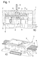
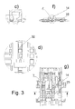
- Fig. 1 shows various views of a connection device 1, which is designed for contacting a flat cable 2, which has a plurality of mutually parallel conductors 3, which may each be surrounded by insulation and embedded in a higher cable sheath 4.
- the flat cable 2 may be routed for example in a lift shaft.
- the connecting device has a multi-part housing 5, which has at least one base section 6 and a cover section 7, which in turn may each be formed in each case in several parts.
- a multi-part housing 5 which has at least one base section 6 and a cover section 7, which in turn may each be formed in each case in several parts.
- the base portion 6 preferably has a plurality of insulation piercing contacts 8 (see Fig. 1a ), which contact individual or all of the conductors 3 of the flat cable 2 when the base section 6 is joined to the cover section 7.
- at least one of the conductors 3 is contacted at two locations spaced apart axially from one another in the main extension direction of the conductor 3, wherein this conductor 3 is to be cut between the contact points to which it is contacted with the contacts 8, as between the contacted ends, for example, an electronics or Like.
- To switch for example, to realize a safety circuit for an elevator.
- the joining of the base portion 6 with the lid portion 7 can - as in the US 7,347,716 B2 described - done with the help of wedge assemblies between these units or in other ways, so with the aid of screws (not shown), with which the cover portion 7 and the base portion 6 are moved toward each other, wherein the insulation piercing contacts 8 to be contacted Contact conductor 3.
- separating element Only in this position is at least one separating element, here a separating pin 9, which may have a cutting edge 10, in the direction shown by the arrow X direction in a corresponding opening 11 - here in the lid portion 7 and / or in the base portion 6 - inserted, which extends to the ribbon cable 2.
- a separating pin 9 which may have a cutting edge 10, in the direction shown by the arrow X direction in a corresponding opening 11 - here in the lid portion 7 and / or in the base portion 6 - inserted, which extends to the ribbon cable 2.
- At least one or more separating pin (s) 9 in each case at least one of the conductors 3 can be severed in a region between the contact points in which this conductor is contacted by the contact elements 8 in order to produce an interruption of this conductor 3.
- a plurality of the separating pins 8 and the openings 11 it is also possible for a plurality of the separating pins 8 and the openings 11 to be provided.
- the separating pins 8 may also be formed as a corresponding pin-like projections on a tool pliers, which is used for severing the conductor 3, and which serves after contacting the conductor 3 for severing the conductor at the designated locations by the release pins on the Pliers are inserted into the openings 11.
- An advantage of this invention is that the contacting of the flat cable and thus the joining of the cover section 7 and the base section 6 is completely completed even before the conductors are severed, ensuring in a simple manner that the conductors 3 to be cut are always in the correct position Place to be severed.
- connection device shown in these figures is different than the embodiment of Fig. 1 designed such that forcibly first with a separator a severing of the flat cable 2 must be made at the at least one or more designated points before the actual wiring of the flat cable using the IDC contacts 8 can take place.
- a particular advantage of this solution is that the contacting of the conductors 3 is not possible if the conductors 3 have not yet been cut through and that nevertheless by the selected Embodiment contacting also the respective severed conductor 3 is carried out after severing the flat cable 2 for the safety circuit on both sides of the separation point.
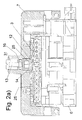
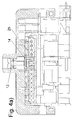
- Fig. 2 to 5 To Fig. 2 to 5 is the lid portion 7 on the base portion 6, which is provided with a pressure plate 25, slidably guided.
- the flat cable 2 is set between the lid portion 7 and the pressure plate 25 on the base portion 6.
- a slider 12 is arranged for severing at least one conductor or a plurality of conductors of the flat cable, wherein the movable in the main extension direction of the cable 2 and perpendicular to the flat cable movable slide 12 has a screw 13 with its end on at least one separating element 14th acts, which in turn is arranged above the flat cable 2, so that by means of screwing the screw 13, the separating element 14 is pressed axially with pin-like projections 26 in the flat cable 2, in turn with a cutting area 17 to sever one or more conductors 3.
- the separating element 14 may be formed according to a particularly preferred embodiment as a U-shaped or comb-like element with two or more of the pin-like projections 26.
- the screw 13 is preferably in a slot 15 e.g. slidably guided in the pressure plate 25 in the main direction of the flat cable 2.
- the separating pin 14 further penetrates a nut 16, which is displaceable on the one hand in the main extension direction of the flat cable 2 and the other hand perpendicular to Flat cable in the lid portion 7 is immovable, so that it forms an abutment on which the screw 13 is supported.
- the U-shaped, bow-like separating element 14 has at its end remote from the screw head or at the free ends of the pin-like projections 26 at least one or more knives 17 for severing the at least one conductor 3.
- the pin-like projections 26 are further formed in each case in the axially adjoining the blade 17 region 18 isolated.
- the separating element 14 is designed as a U-shaped bracket, wherein a central franking 28 in the separating element has the shape of a T.
- a central franking 28 in the separating element has the shape of a T.
- the franking 28 is wide enough to be guided over a broadening or a stop 19 in the pressure plate 25, whereas the franking 28 is too narrow in its narrow region 30 for this purpose.
- it is therefore necessary to first pierce them with the separating element 14 perpendicular to the main extension direction of the conductor 3, and then to move the lid portion 7 in the contacting position can.
- Step 1 through Step 4 the screwing (and thus interrupting) of the flat cable 2, inter alia, by means of a screwdriver 27 (see Fig. 5 ) in four steps, labeled Step 1 through Step 4.
- Step1 The lid portion 7 together with the pressure plate 25 and the slide 12 are placed on the base portion 6 ( Fig. 2 ).
- Step2 The bow-like separating element 14 guided on a rail-like web 32 into the slot 15 of the pressure plate 25 runs against the stop 19 on the web 32, which is formed on the pressure plate 25, for example, so that the lid section 7 is blocked in this position and not further in Ladder direction can be moved ( Fig. 3 ).
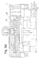
- Step 3 The flat cable 2 is punched out by screwing the screw 13 with the separating element 14.
- the cutting element releases the slide 12 and the cover gate 7 on the pressure plate 27 again for movement in the conductor direction ( Fig. 4 ).
- Step 4 Then, the flat cable 2 is contacted with the insulation piercing contacts 8, for example by means of a screwdriver, which shifts the lid portion (7) at the base portion (6) so that the wedge assembly comes into action and presses the flat cable into the IDC contacts.
- the safety circuit is feasible ( Fig. 5 ).
- Corresponding guide means are provided in the cover section and in the base section, which permit a displacement and contacting of the relatively movable housing sections in the manner of the state of the prior art discussed.
- a particular advantage of this solution is that the punching of the flat cable 2 can not be forgotten.
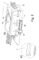
- a connecting device 34 designed here as a socket is further formed, which is conductively connected to the contacts 8 for contacting the cable, here the flat cable, and which serves to external conductors outside the housing 5 with a plug (not shown) conductive to the contacts 8 to connect, for example, to realize a T-shaped connection to the flat cable.
- a protective device 33 is further formed on another relative to the first movable portion of the housing 5, in particular on the lid portion 7, which is designed here as a collar which moves with the lid portion 7 to contact the connecting device 34, here with a plug, to prevent as long as the Bescharisvorgang the flat cable with the contacts 8 and preferably also the cutting is not completed, ie here, until the Cover section 7 from the position of Fig. 2 in the contact position of Fig. 5 was moved.
- the collar 33 moves with the lid portion 7 from a position in which it partially covers the connecting device and thus prevents plugging into the connecting device 34 (FIG. Fig. 2 to Fig. 4 ) to a position laterally of the socket in which a plug can be inserted into said socket ( Fig. 5 ).
- This protection device ensures that the connection device can not be contacted until the wiring process of the flat cable has been completely completed. It could also be provided in other ways relatively movable housing sections, so at relatively rotatable sections. The same applies to the other features in this description.
Abstract
Description
Die Erfindung betrifft eine Anschlussvorrichtung zur Kontaktierung von Leitern eines durchgehenden Kabels, insbesondere eines durchgehenden Flachkabels, das zur Verlegung in einem Liftschacht geeignet ist, nach dem Oberbegriff des Anspruchs 1.The invention relates to a connecting device for contacting conductors of a continuous cable, in particular a continuous flat cable, which is suitable for installation in a lift shaft, according to the preamble of
Anschlussvorrichtungen für die Enden von Flachkabeln offenbaren die
Eine alternative Lösung zeigt die
Bei dieser an sich bewährten Lösung müssen die Kabel genau vorab an bestimmten Stellen durchtrennt werden. Die Vorabkonfektionierung eines Kabels mit entsprechenden Unterbrechungen in den einzelnen Kabeln erscheint noch optimierbar.In this proven solution, the cables must be cut in advance in specific places. The pre-assembly of a cable with corresponding interruptions in the individual cables still appears optimizable.
Einen anderen Weg zum Kontaktieren von Liftschacht-Flachkabeln unter gleichzeitiger Realisierung eines Sicherheitskreises zeigt die
Die Erfindung hat daher die Aufgabe, diese gattungsgemäße Konstruktion weiter zu optimieren.The invention therefore has the task of further optimizing this generic construction.
Die Erfindung löst diese Aufgabe durch den Gegenstand des Anspruchs 1. Sie löst diese Aufgabe ferner durch die alternativen Erfindungen und Gegenstände der Ansprüche 4 und 16.The invention solves this problem by the subject matter of
Vorteilhafte Ausgestaltungen sind den Unteransprüchen zu entnehmen.Advantageous embodiments can be found in the dependent claims.
Nachfolgend wird die Erfindung unter Bezug auf die Zeichnung anhand von Ausführungsbeispielen näher beschrieben. Es zeigt:
- Fig. 1a-c
- verschiedene Ansichten einer ersten erfindungsgemäßen Anschlussvorrichtung ;
- Fig. 2a-2g bis 5a-5f
- verschiedene Ansichten einer weiteren Anschlussvorrichtung und die Beschaltung eines Flachkabels mit dieser Anschlussvorrichtung in vier aufeinander folgenden Schritten;
- Fig. 6a - c
- verschiedene Ansichten einer weiteren erfindungsgemäßen Anschlussvorrichtung.
- Fig. 1a-c
- different views of a first connecting device according to the invention;
- Fig. 2a-2g to 5a-5f
- various views of a further connection device and the wiring of a flat cable with this connection device in four successive steps;
- Fig. 6a - c
- different views of another connecting device according to the invention.
Die Anschlussvorrichtung weist ein mehrteiliges Gehäuse 5 auf, welches zumindest einen Grundabschnitt 6 und einen Deckelabschnitt 7 aufweist, die wiederum jeweils vorzugsweise mehrteilig ausgebildet sein können. Insoweit wird auf die
Der Grundabschnitt 6 weist vorzugsweise eine Mehrzahl von isolationsdurchdringenden Kontakten 8 (siehe
Das Zusammenfügen des Grundabschnittes 6 mit dem Deckelabschnitt 7 kann - wie in der
Anders als nach
Erst in dieser Position wird wenigstens ein Trennelement, hier ein Trennstift 9, der eine Schneidkante 10 aufweisen kann, in der durch den Pfeil X dargestellten Richtung in eine entsprechende Öffnung 11 - hier im Deckelabschnitt 7 und/oder im Grundabschnitt 6 - eingefügt, welche sich bis zum Flachbandkabel 2 erstreckt.Only in this position is at least one separating element, here a separating pin 9, which may have a
Mit dem wenigstens einen oder den mehreren Trennstift(en) 9 kann jeweils wenigstens einer der Leiter 3 in einem Bereich zwischen den Kontaktstellen, in dem dieser Leiter von den Kontaktelementen 8 kontaktiert wird, durchtrennt werden, um eine Unterbrechung dieses Leiters 3 zu erzeugen. Um mehrere der Leiter 3 zu durchtrennen, können auch mehrere der Trennstifte 8 und der Öffnungen 11 vorgesehen sein.With the at least one or more separating pin (s) 9, in each case at least one of the
Es ist auch denkbar, als die Trennstifte 8 Schraubstifte zu verwenden, die drehend den jeweiligen Leiter 3 durchtrennen.It is also conceivable to use as the separating
Die Trennstifte 8 können auch als entsprechende stiftartige Ansätze an einem Werkzeug einer Zange ausgebildet sein, die zum Durchtrennen der Leiter 3 genutzt wird, und die nach dem Kontaktieren der Leiter 3 zum Durchtrennen der Leiter an den dazu bestimmten Stellen dient, indem die Trennstifte an der Zange in die Öffnungen 11 gesteckt werden.The separating
An dieser Erfindung ist vorteilhaft, dass dadurch, dass bereits vor dem Durchtrennen der Leiter das Kontaktieren des Flachkabels und damit das Zusammenfügen von Deckelabschnitt 7 und Grundabschnitt 6 vollständig abgeschlossen ist, in einfacher Weise sichergestellt wird, dass die zu durchtrennenden Leiter 3 stets an der richtigen Stelle durchtrennt werden.An advantage of this invention is that the contacting of the flat cable and thus the joining of the
Eine alternative Lösung zeigen die
Die in diesen Figuren gezeigte Anschlussvorrichtung ist anders als die Ausführungsform der
Erreicht wird dies beispielhaft nach
Nach
Zunächst wird das Flachkabel 2 zwischen den Deckelabschnitt 7 und die Druckplatte 25 auf dem Grundabschnitt 6 gesetzt.First, the
Im Deckelabschnitt 7 ist als Trennvorrichtung ein Schieber 12 zum Durchtrennen wenigstens eines Leiters oder mehrerer Leiter des Flachkabels angeordnet, wobei der in Haupterstreckungsrichtung des Kabels 2 verschiebliche und senkrecht zum Flachkabels bewegliche Schieber 12 eine Schraube 13 aufweist, die mit ihrem Ende auf wenigstens ein Trennelement 14 einwirkt, das wiederum oberhalb des Flachkabels 2 angeordnet ist, so dass mittels Eindrehen der Schraube 13 das Trennelement 14 mit stiftartigen Ansätzen 26 axial in das Flachkabel 2 gedrückt wird, um wiederum mit einem Schneidbereich 17 einen oder mehrere Leiter 3 zu durchtrennen.In the
Das Trennelement 14 kann nach einer besonders bevorzugten Ausgestaltung als U-förmiges oder kammartiges Element mit zwei oder mehr der stiftartigen Ansätze 26 ausgebildet sein.The separating
Die Schraube 13 ist vorzugsweise in einer Kulisse 15 z.B. in der Druckplatte 25 in Haupterstreckungsrichtung des Flachkabels 2 verschieblich geführt.The
Der Trennstift 14 durchsetzt ferner eine Mutter 16, die einerseits in der Haupterstreckungsrichtung des Flachkabels 2 verschieblich ist und die andererseits senkrecht zu Flachkabel im Deckelabschnitt 7 unbeweglich ist, so dass sie ein Widerlager bildet, an dem sich die Schraube 13 abstützt.The separating
Das u-förmige, bügelartige Trennelement 14 weist an seinem vom Schraubkopf abgewandten Ende bzw. an den freien Enden der stiftartigen Ansätze 26 wenigstens eines oder mehrere Messer 17 zum Durchtrennen des wenigstens einen Leiters 3 auf. Die stiftartigen Ansätze 26 sind ferner jeweils in dem sich axial an die Messer 17 anschließenden Bereich 18 isoliert ausgebildet.The U-shaped, bow-like separating
Das Trennelement 14 ist als U-förmiger Bügel ausgebildet, wobei eine mittige Freimachung 28 in dem Trennelement die Form eines T aufweist. Im Querschenkelbereich 29 des T ist die Freimachung 28 breit genug, um über eine Verbreiterung bzw. einen Anschlag 19 in der Druckplatte 25 geführt zu werden, wohingegen die Freimachung 28 in ihrem Schmalbereich 30 dafür zu schmal ist. Um in der Kulisse verschieben zu werden, ist es daher notwendig, mit dem Trennelement 14 zunächst senkrecht zur Haupterstreckungsrichtung der Leiter 3 diese zu durchstanzen, um dann den Deckelabschnitt 7 in die Kontaktierungsposition bewegen zu können.The separating
Im Einzelnen erfolgt das Eindrehen (und somit Unterbrechen) des Flachkabels 2 u.a. mit Hilfe eines Schraubendrehers 27 (siehe
Step1 Der Deckelabschnitt 7 samt der Druckplatte 25 und der Schieber 12 werden auf den Grundabschnitt 6 aufgesetzt (
Step2: Das auf einem schienenartigen Steg 32 in den Kulisse 15 der Druckplatte 25 geführte bügelartige Trennelement 14 läuft gegen den Anschlag 19 am Steg 32, der z.B. an der Druckplatte 25 ausgebildet ist, so dass der Deckelabschnitt 7 in dieser Stellung blockiert und nicht weiter in Leiterrichtung bewegt werden kann (
Step3: Das Flachkabel 2 wird durch das Einschrauben der Schraube 13 mit dem Trennelement 14 ausgestanzt. Das Schneidelement gibt den Schieber 12 und den Deckelanschnitt 7 auf der Druckplatte 27 wieder zur Bewegung in Leiterrichtung frei (
Step4: Sodann wird das Flachkabel 2 mit den isolationsdurchdringenden Kontakten 8 z.B. mit Hilfe eines Schraubendrehers kontaktiert, der den Deckelabschnitt (7) am Grundabschnitt (6) verschiebt, so dass die Keilanordnung zur Wirkung kommt und das Flachkabel in die IDC-Kontakte drückt.. Damit ist der Sicherheitskreis realisierbar (
Im Deckelabschnitt und im Grundabschnitt sind korrespondierende Führungsmittel vorgesehen, die ein Verschieben und Kontaktieren der relativ beweglichen Gehäuseabschnitte nach Art des Standes des diskutierten Standes der Technik erlauben.Corresponding guide means are provided in the cover section and in the base section, which permit a displacement and contacting of the relatively movable housing sections in the manner of the state of the prior art discussed.
Ein besonderer Vorteil dieser Lösung ist, dass das Ausstanzen des Flachkabels 2 nicht vergessen werden kann.A particular advantage of this solution is that the punching of the
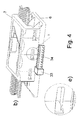
An einem Abschnitt des Gehäuses 5 der Ausführung nach
Vorzugsweise ist an einem anderen, relativ zum ersten beweglichen Abschnitt des Gehäuse 5, insbesondere am Deckelabschnitt 7, ferner eine Schutzeinrichtung 33 ausgebildet, die hier als Kragen ausgestaltet ist, der sich mit dem Deckelabschnitt 7 bewegt, um ein Kontaktieren der Anschlussvorrichtung 34, hier mit einem Stecker, zu verhindern, solange der Beschaltungsvorgang des Flachkabels mit den Kontakten 8 und vorzugsweise auch das Durchtrennen nicht abgeschlossen ist, d.h. hier, bis der Deckelabschnitt 7 aus der Position der
Der Kragen 33 bewegt sich mit dem Deckelabschnitt 7 aus einer Position, in welcher er die Anschlussvorrichtung teilweise verdeckt und damit ein Einstecken eines Steckers in die Anschlussvorrichtung 34 verhindert (
Diese Schutzeinrichtung stellt sicher, dass die Anschlussvorrichtung erst kontaktiert werden kann, wenn der Beschaltungsvorgang des Flachkabels vollständig abgeschlossen worden ist. Sie könnte auch bei auf andere Weise relativ beweglichen Gehäuseabschnitten vorgesehen sein, so bei relativ drehbaren Abschnitten. Analoges gilt für die weiteren Merkmale in dieser Beschreibung.This protection device ensures that the connection device can not be contacted until the wiring process of the flat cable has been completely completed. It could also be provided in other ways relatively movable housing sections, so at relatively rotatable sections. The same applies to the other features in this description.
Nach
- Anschlussvorrichtungconnection device
- 11
- Flachkabelflat cable
- 22
- Leiterladder
- 33
- Kabelmantelcable sheath
- 44
- Gehäusecasing
- 55
- Grundabschnittbase portion
- 66
- Deckelabschnittcover section
- 77
- Kontaktecontacts
- 88th
- Trennstiftunlocking pin
- 99
- Schneidkantecutting edge
- 1010
- Öffnungopening
- 1111
- Schieberpusher
- 1212
- Schraubescrew
- 1313
- Trennstiftunlocking pin
- 1414
- Längsschlitzlongitudinal slot
- 1515
- Muttermother
- 1616
- Messerknife
- 1717
- BereichArea
- 1818
- Anschlagattack
- 1919
- Kabelabschnittencable sections
- 20, 2120, 21
- PiercingkontaktePiercing contacts
- 22, 2322, 23
- Stromschieneconductor rail
- 2424
- Druckplatteprinting plate
- 2525
- Ansätzeapproaches
- 2626
- Schraubendreherscrewdriver
- 2727
- Freimachungfranking
- 2828
- QuerschenkelbereichCross leg region
- 2929
- Schmalbereichnarrow range
- 3030
- Längsschlitzlongitudinal slot
- 3131
- Stegweb
- 3232
- Kragencollar
- 3333
- Anschlussvorrichtungconnection device
- 3434
Claims (16)
gekennzeichnet durch
marked by
Applications Claiming Priority (1)
| Application Number | Priority Date | Filing Date | Title |
|---|---|---|---|
| DE202008008696U DE202008008696U1 (en) | 2008-06-28 | 2008-06-28 | Connecting device for multi-conductor cable |
Publications (2)
| Publication Number | Publication Date |
|---|---|
| EP2139074A2 true EP2139074A2 (en) | 2009-12-30 |
| EP2139074A3 EP2139074A3 (en) | 2014-03-26 |
Family
ID=41110772
Family Applications (1)
| Application Number | Title | Priority Date | Filing Date |
|---|---|---|---|
| EP09163706.6A Withdrawn EP2139074A3 (en) | 2008-06-28 | 2009-06-25 | Connection device for multi-conductor cables |
Country Status (2)
| Country | Link |
|---|---|
| EP (1) | EP2139074A3 (en) |
| DE (1) | DE202008008696U1 (en) |
Citations (6)
| Publication number | Priority date | Publication date | Assignee | Title |
|---|---|---|---|---|
| DE2535933A1 (en) | 1974-08-15 | 1976-02-26 | Aumann Vital L | ELECTRICAL CONNECTION SYSTEM AND PROCEDURE FOR ITS CREATION AND TESTING |
| DE3422607C2 (en) | 1983-06-18 | 1993-02-25 | ||
| US5429526A (en) | 1993-04-28 | 1995-07-04 | Ann; Young S. | Wire connector |
| DE4402837A1 (en) | 1994-01-31 | 1995-08-03 | Daetwyler Ag | Flat cable |
| DE4436829A1 (en) | 1994-10-14 | 1996-04-18 | Siemens Ag | Electrical contact for contacting form-coded multi-core ribbon cable |
| EP1855356A1 (en) | 2006-05-11 | 2007-11-14 | Weidmüller Interface GmbH & Co. KG | Connecting device for multiconductor cables |
Family Cites Families (8)
| Publication number | Priority date | Publication date | Assignee | Title |
|---|---|---|---|---|
| US4062615A (en) * | 1976-12-06 | 1977-12-13 | Thomas & Betts Corporation | Electrical contact |
| DE3711675A1 (en) * | 1987-04-07 | 1988-10-27 | Krone Ag | CORE CONNECTOR FOR CABLE CORDS, ESPECIALLY TELECOMMUNICATION CABLES |
| US5174782A (en) * | 1992-01-06 | 1992-12-29 | Molex Incorporated | Electrical cable clamping device with cable foil grounding means |
| JPH08162177A (en) * | 1994-12-05 | 1996-06-21 | Yazaki Corp | Pressure contact method of wire to pressure contact connector and pressure contact connector |
| JP3541540B2 (en) * | 1996-02-05 | 2004-07-14 | 住友電装株式会社 | Wire harness using insulation displacement joint connector |
| DE59906372D1 (en) * | 1999-10-15 | 2003-08-28 | Endress & Hauser Gmbh & Co Kg | Electrical safety device |
| JP3935036B2 (en) * | 2002-09-27 | 2007-06-20 | 株式会社フジクラ | Flat harness |
| DE202006019520U1 (en) * | 2006-12-21 | 2008-04-30 | Weidmüller Interface GmbH & Co. KG | Connecting device for multi-conductor cable |
-
2008
- 2008-06-28 DE DE202008008696U patent/DE202008008696U1/en not_active Expired - Lifetime
-
2009
- 2009-06-25 EP EP09163706.6A patent/EP2139074A3/en not_active Withdrawn
Patent Citations (7)
| Publication number | Priority date | Publication date | Assignee | Title |
|---|---|---|---|---|
| DE2535933A1 (en) | 1974-08-15 | 1976-02-26 | Aumann Vital L | ELECTRICAL CONNECTION SYSTEM AND PROCEDURE FOR ITS CREATION AND TESTING |
| DE3422607C2 (en) | 1983-06-18 | 1993-02-25 | ||
| US5429526A (en) | 1993-04-28 | 1995-07-04 | Ann; Young S. | Wire connector |
| DE4402837A1 (en) | 1994-01-31 | 1995-08-03 | Daetwyler Ag | Flat cable |
| DE4436829A1 (en) | 1994-10-14 | 1996-04-18 | Siemens Ag | Electrical contact for contacting form-coded multi-core ribbon cable |
| EP1855356A1 (en) | 2006-05-11 | 2007-11-14 | Weidmüller Interface GmbH & Co. KG | Connecting device for multiconductor cables |
| US7347716B2 (en) | 2006-05-11 | 2008-03-25 | Weidmüller Interface GmbH & Co. KG | Connector arrangement for multi-conductor cables |
Also Published As
| Publication number | Publication date |
|---|---|
| DE202008008696U1 (en) | 2009-11-19 |
| EP2139074A3 (en) | 2014-03-26 |
Similar Documents
| Publication | Publication Date | Title |
|---|---|---|
| EP1855356B1 (en) | Connecting device for multiconductor cables | |
| EP1936747B1 (en) | Connection device for multi-conductor cables | |
| EP2019449B1 (en) | Screw-clamp and method for manufacturing thereof | |
| DE19835459C2 (en) | Terminal for electrical conductors | |
| EP1191633B1 (en) | Terminal block with insulation displacement terminals and members to contact the wires to the terminals | |
| EP3021421B1 (en) | Connection device for multi-conductor cables | |
| EP1008205B1 (en) | Terminal block for connecting insulated conductors without stripping | |
| EP3117487B1 (en) | Surge protection device with at least one surge protection unit | |
| EP1691449B1 (en) | Device for electrically connecting at least two isolated main conductors of a power supply cable, in particular tapping clamp | |
| EP1523065B1 (en) | Electrical terminal | |
| DE102005005917B4 (en) | Terminal for an insulated electrical conductor | |
| DE19937720C2 (en) | Connection device with insulation penetrating slot for an electrical wire | |
| EP2139074A2 (en) | Connection device for multi-conductor cables | |
| DE102011001152B4 (en) | Contact element and contact element assembly | |
| EP3759766B1 (en) | Overvoltage protection device with at least one overvoltage protection unit, consisting of a socket part and a plug part which can be connected to the socket part | |
| EP1972032B1 (en) | Insulation displacement contact for braided wires | |
| DE102009040646B3 (en) | Device for separating contact tongue i.e. bridge bar, from plug-in bridge i.e. plug-in bridge system, in automated tool, has tool with cutting edge, and bridge bar that is accurately fitted into contours, which are formed in tool | |
| EP3151337B1 (en) | Ribbon cable and method for isolation of ribbon cables | |
| EP1279206B1 (en) | Insulation-piercing connecting device | |
| EP1463151A2 (en) | Connection device with piercing contact | |
| DE102014116488A1 (en) | Connecting device for multi-conductor cable | |
| EP1503456B1 (en) | Electrical connector more especially with a rounded plug | |
| DE10243107B4 (en) | Terminal block and guide sleeve | |
| EP1120859A2 (en) | Terminal block with an insulation displacement terminal | |
| DE20216865U1 (en) | Insulation piercing clamp connection for strip clamps of at least one insulated electric conductor, with two adjacent insulation piercing clamp shank with intermediate gap widening |
Legal Events
| Date | Code | Title | Description |
|---|---|---|---|
| PUAI | Public reference made under article 153(3) epc to a published international application that has entered the european phase |
Free format text: ORIGINAL CODE: 0009012 |
|
| AK | Designated contracting states |
Kind code of ref document: A2 Designated state(s): AT BE BG CH CY CZ DE DK EE ES FI FR GB GR HR HU IE IS IT LI LT LU LV MC MK MT NL NO PL PT RO SE SI SK TR |
|
| PUAL | Search report despatched |
Free format text: ORIGINAL CODE: 0009013 |
|
| AK | Designated contracting states |
Kind code of ref document: A3 Designated state(s): AT BE BG CH CY CZ DE DK EE ES FI FR GB GR HR HU IE IS IT LI LT LU LV MC MK MT NL NO PL PT RO SE SI SK TR |
|
| AX | Request for extension of the european patent |
Extension state: AL BA RS |
|
| RIC1 | Information provided on ipc code assigned before grant |
Ipc: H01R 12/67 20110101AFI20140218BHEP Ipc: H01R 4/24 20060101ALI20140218BHEP |
|
| 17P | Request for examination filed |
Effective date: 20140707 |
|
| RBV | Designated contracting states (corrected) |
Designated state(s): AT BE BG CH CY CZ DE DK EE ES FI FR GB GR HR HU IE IS IT LI LT LU LV MC MK MT NL NO PL PT RO SE SI SK TR |
|
| STAA | Information on the status of an ep patent application or granted ep patent |
Free format text: STATUS: THE APPLICATION IS DEEMED TO BE WITHDRAWN |
|
| 18D | Application deemed to be withdrawn |
Effective date: 20140927 |
|
| REG | Reference to a national code |
Ref country code: DE Ref legal event code: R079 Free format text: PREVIOUS MAIN CLASS: H01R0012080000 Ipc: H01R0012770000 |
|
| REG | Reference to a national code |
Ref country code: DE Ref legal event code: R079 Free format text: PREVIOUS MAIN CLASS: H01R0012080000 Ipc: H01R0012770000 Effective date: 20150512 |