EP2139053B1 - Dispositif de limitation de courant - Google Patents
Dispositif de limitation de courant Download PDFInfo
- Publication number
- EP2139053B1 EP2139053B1 EP08305352A EP08305352A EP2139053B1 EP 2139053 B1 EP2139053 B1 EP 2139053B1 EP 08305352 A EP08305352 A EP 08305352A EP 08305352 A EP08305352 A EP 08305352A EP 2139053 B1 EP2139053 B1 EP 2139053B1
- Authority
- EP
- European Patent Office
- Prior art keywords
- current limiting
- limiting unit
- superconducting elements
- current
- cooling medium
- Prior art date
- Legal status (The legal status is an assumption and is not a legal conclusion. Google has not performed a legal analysis and makes no representation as to the accuracy of the status listed.)
- Not-in-force
Links
- 238000009413 insulation Methods 0.000 claims abstract description 40
- 239000002826 coolant Substances 0.000 claims description 33
- 238000003032 molecular docking Methods 0.000 claims description 12
- 238000001816 cooling Methods 0.000 claims description 7
- 230000008878 coupling Effects 0.000 claims description 2
- 238000010168 coupling process Methods 0.000 claims description 2
- 238000005859 coupling reaction Methods 0.000 claims description 2
- IJGRMHOSHXDMSA-UHFFFAOYSA-N Atomic nitrogen Chemical compound N#N IJGRMHOSHXDMSA-UHFFFAOYSA-N 0.000 description 26
- 239000007788 liquid Substances 0.000 description 14
- 229910052757 nitrogen Inorganic materials 0.000 description 13
- 239000007789 gas Substances 0.000 description 12
- 239000000463 material Substances 0.000 description 6
- 239000004020 conductor Substances 0.000 description 5
- 239000002887 superconductor Substances 0.000 description 5
- 230000015572 biosynthetic process Effects 0.000 description 3
- 238000004519 manufacturing process Methods 0.000 description 3
- 239000002184 metal Substances 0.000 description 3
- 238000010276 construction Methods 0.000 description 2
- 239000012809 cooling fluid Substances 0.000 description 2
- 238000007599 discharging Methods 0.000 description 2
- 238000005516 engineering process Methods 0.000 description 2
- 239000012774 insulation material Substances 0.000 description 2
- 239000012811 non-conductive material Substances 0.000 description 2
- 239000000758 substrate Substances 0.000 description 2
- 229910021521 yttrium barium copper oxide Inorganic materials 0.000 description 2
- UFHFLCQGNIYNRP-UHFFFAOYSA-N Hydrogen Chemical compound [H][H] UFHFLCQGNIYNRP-UHFFFAOYSA-N 0.000 description 1
- OSOKRZIXBNTTJX-UHFFFAOYSA-N [O].[Ca].[Cu].[Sr].[Bi] Chemical compound [O].[Ca].[Cu].[Sr].[Bi] OSOKRZIXBNTTJX-UHFFFAOYSA-N 0.000 description 1
- BTGZYWWSOPEHMM-UHFFFAOYSA-N [O].[Cu].[Y].[Ba] Chemical compound [O].[Cu].[Y].[Ba] BTGZYWWSOPEHMM-UHFFFAOYSA-N 0.000 description 1
- 238000009825 accumulation Methods 0.000 description 1
- 230000006978 adaptation Effects 0.000 description 1
- 238000009835 boiling Methods 0.000 description 1
- 239000013590 bulk material Substances 0.000 description 1
- 238000005266 casting Methods 0.000 description 1
- 238000000224 chemical solution deposition Methods 0.000 description 1
- 238000005229 chemical vapour deposition Methods 0.000 description 1
- 238000004891 communication Methods 0.000 description 1
- 239000000112 cooling gas Substances 0.000 description 1
- 230000000694 effects Effects 0.000 description 1
- 230000005684 electric field Effects 0.000 description 1
- 238000010292 electrical insulation Methods 0.000 description 1
- 230000002708 enhancing effect Effects 0.000 description 1
- 239000001307 helium Substances 0.000 description 1
- 229910052734 helium Inorganic materials 0.000 description 1
- SWQJXJOGLNCZEY-UHFFFAOYSA-N helium atom Chemical compound [He] SWQJXJOGLNCZEY-UHFFFAOYSA-N 0.000 description 1
- 239000001257 hydrogen Substances 0.000 description 1
- 229910052739 hydrogen Inorganic materials 0.000 description 1
- 229910001092 metal group alloy Inorganic materials 0.000 description 1
- 238000000034 method Methods 0.000 description 1
- 239000000203 mixture Substances 0.000 description 1
- 229910052754 neon Inorganic materials 0.000 description 1
- GKAOGPIIYCISHV-UHFFFAOYSA-N neon atom Chemical compound [Ne] GKAOGPIIYCISHV-UHFFFAOYSA-N 0.000 description 1
- 238000005192 partition Methods 0.000 description 1
- 238000005240 physical vapour deposition Methods 0.000 description 1
- 238000011084 recovery Methods 0.000 description 1
- 238000005057 refrigeration Methods 0.000 description 1
- 230000000630 rising effect Effects 0.000 description 1
- 238000007789 sealing Methods 0.000 description 1
- 238000000926 separation method Methods 0.000 description 1
- 238000005245 sintering Methods 0.000 description 1
- 238000005476 soldering Methods 0.000 description 1
- 239000010409 thin film Substances 0.000 description 1
Images

Classifications
-
- H—ELECTRICITY
- H10—SEMICONDUCTOR DEVICES; ELECTRIC SOLID-STATE DEVICES NOT OTHERWISE PROVIDED FOR
- H10N—ELECTRIC SOLID-STATE DEVICES NOT OTHERWISE PROVIDED FOR
- H10N60/00—Superconducting devices
- H10N60/30—Devices switchable between superconducting and normal states
Definitions
- the present invention relates to an improved arrangement of superconducting elements in a current limiting device in particularly optimized for high voltage applications. Further, the present invention relates to such a current limiting device which can be easily adapted to the particular requirements of a specific application such as specific voltage level of said application etc.
- Superconductors offer a great potential as resistive fault current limiters which enable rapid and effective current limitation, automatic recovery and negligible impedance during normal operation. They are especially an enabling technology for other superconducting applications in the high voltage technology, for example superconducting cables.
- a superconducting fault current limiter comprises one or more superconducting elements housed in an insulating housing such as a cryostat, filled with a cooling medium for cooling the superconducting elements below their critical temperature Tc at which they exhibit superconducting properties.
- the critical temperature depends on the specific superconducting material. Suitable cooling mediums are for example nitrogen, helium, neon, hydrogen or mixtures thereof in their liquid state.
- Preferred superconducting materials are the high temperature superconductors such as BSCCO (bismuth-strontium-calcium-copper-oxide) and YBCO (yttrium-barium-copper-oxide) which have a critical temperature in the range of 67 K and 110 K.
- BSCCO bismuth-strontium-calcium-copper-oxide
- YBCO yttrium-barium-copper-oxide
- liquid nitrogen can be used as cooling medium which is preferred in view of costs.
- the first parameter is the nominal current at which the system will be operated as well as the limitation level at which the system shall limit the current.
- the superconducting elements must be selected in view of their current carrying capacity as well as in view of their limitation properties.
- one superconducting element or two or more superconducting elements electrically connected in parallel may be necessary.
- the second parameter is the voltage level at which the current limiter shall be operated. By the voltage level the necessary number of superconducting elements which have to be electrically connected in series is determined.
- Liquid nitrogen typically used as cooling medium, also has very good insulation properties and, thus, helps to provide electrical insulation within the fault current limiter.
- EP 1217708 A discloses a fault current limiter comprising a cryostat having a partition with good thermal conductivity that divides the volume of the cryostat into an inner partial volume and an outer partial volume which surrounds the inner partial volume.
- One or more superconducting elements and a cooling fluid are located in the inner partial volume, while the outer partial volume contains a liquid cooling medium as refrigeration reservoir.
- the liquid cooling medium and the cooling fluid are therefore accommodated in separate parts of the cryostat and in this case may also be at different pressures.
- the present invention relates to a current limiting unit encasing one or more superconducting elements according to claim 9 and the use of such current limiting unit for the modular design of a fault current limiter.
- the present invention is based on the separation of the necessary cooling of the superconducting elements within a fault current limiter and the insulation material necessary for high voltage insulation.
- the present invention relates to a fault current limiter which can be variably designed by standardized current limiting units and modules allowing easy adaptation and design, respectively, of a fault current limiter for the specific requirements of different applications.
- any superconducting element suitable for fault current limiting application can be used.
- the superconducting element is made of a high temperature superconducting material, such as mentioned above.
- the shape of the superconducting element is not particularly restricted provided that it is suitable for the use in a fault current limiter.
- the superconducting element can be composed of a bulk material, for example, superconducting elements obtainable by a sintering or melt casting method.
- the superconducting element can be composed of a superconducting layer deposited onto a substrate, for example such as known as coated conductors wherein a thin-film of superconductor material is provided onto a substrate, typically made of metal, by physical vapor deposition, chemical vapor deposition or chemical solution deposition etc..
- the superconducting element has a cylindrical shape, such as a rod, tube or coil, or a plate shape.
- the superconducting element(s) are arranged within a current limiting unit which spatially separates the superconducting element(s) from the surrounding, typically the interior of an insulation housing such as a cryostat.
- a current supply is provided for connecting the superconducting elements within the current liming unit to the grid.
- the current supply is simultaneously used for feeding and discharging cooling medium to and from the current limiting unit.
- the current supply is a tube that has a hollow interior.
- the current supply extends through the current limiting unit into the interior of the current limiting unit to the superconducting elements.
- an opening is provided.
- the current supplies form part of the first cooling medium circuit which serves to cool the superconducting elements.
- the superconducting element is connected to a current supply at its opposing ends.
- the superconducting element(s) present within the current limiting unit can be arranged within a holder.
- the holder is.suited to connect the superconducting elements electrically in parallel with each other. Simultaneousty, by the holder the arrangement of superconducting elements electrically connected in parallel are connected electrically in series within the system.
- the casing of the current limiting unit of the present invention can be formed by an electrically non-conductive material.
- the casing is formed of a shielding electrode surrounding the superconducting elements with open faces, if any, being closed by an electrically non-conductive cover.
- the outer surface of the current limiting unit is essentially smooth and has an essentially round shape without square etches and spikes for avoiding accumulation of electrical charge which would promote flash over.
- the superconducting elements are substantially equal to each other.
- the current limiting unit of the present invention can be used as a standardized component for designing a standardized fault current limiter which can be easily adapted to the specific requirements of an intended application by varying the numbers of standardized current limiting units within the cryostat.
- a number of current limiting units are arranged within a cryostat and are connected electrically in series, for example, by the current supply tubes connected to the individual current limiting units.
- cooling medium for supplying the surrounding interior of the insulation housing with cooling medium (second cooling medium circuit) any conventional supply system can be used which is generally known in the art.
- the holder 3 with the superconducting elements 2 is surrounded by shielding electrode 4 enclosing the superconducting elements 2 laterally and forming the bottom.
- shielding electrode 4 enclosing the superconducting elements 2 laterally and forming the bottom.
- the shielding electrode 4 can be formed of a sheet of an electrically conductive material such as a metal. Shielding electrodes and manufacturing thereof are in principle known.
- the shielding electrode 4 with the cover 5 forms a casing with at least the outer surface having an almost cylindrical shape.
- the lower and upper edge of the cylindrical body can be rounded by providing for example a tube 7 of electrically conductive material running along the circumference.
- the tube 7, also referred to as “toroid”, is made of the same material as the shielding electrode 4.
- tubular current supply tubes 6a, 6b are provided made of electrically conductive material, which are in electrical connection with the holder 3.
- each of the tubes 6a and 6b simultaneously serve to supply and discharge cooling medium to and from the current limiting unit 1.
- each of the tubes 6a and 6b has an opening 8 in its end portion extending between the bottom plate and top cover 5, respectively, and the holder 3.
- Holder 3 can be composed by an upper and an lower plate or stripe for holding the respective ends of the superconductor elements 2.
- the holder 3 can have the shape of a stripe or plate which is designed to hold the respective ends of the superconducting elements. To this, depressions can be provided in the holder having a shape fitting to the shape of the ends of the superconducting elements. The ends of the superconducting elements can be fixed to the holder, for example by soldering or similar.
- portions holding the ends can be designed to act as a clamping bush.
- suitable holders is generally known in the field of fault current limiters using superconducting elements.
- the holder 3 is designed to connect the individual superconducting elements 2 electrically in parallel and, simultaneously, to electrically connect the individual superconducting elements 2 with the supply tubes 6a and 6b, respectively.
- holder 3, or at least respective parts of holder 3, are made of electrically conductive material, such as a metal or metal alloy.
- the passage of the supply tubes through the opening is leak prove for avoiding leaking of the cooling medium or gas bubbles to the surrounding. According to need a suitable sealing can be provided.
- any gas bubbles formed in fault current event are entrapped within the current limiting unit 1 and can leave the unit only via openings 8 within supply tubes 6a, b.
- the overall current limiting unit is housed in an insulation housing indicated by reference number 9, such as a cryostat.
- the superconducting elements 2 preferably have an elongated shape such as a tape, tube, rod or similar.
- superconducting elements 2 within a unit 1 are almost identical.
- the maximal electrical voltage which can occur within the unit, corresponds to the voltage drop along the superconducting elements 2 and is generated between the superconducting elements 2 and the shielding electrode 4.
- the electrical overall potential of the unit is relieved over the distance between the unit and any adjacent conductive component such as, for example, further units or the grounded insulation housing.
- the interior of the insulation housing is provided with a homogeneous insulation material, such as liquid nitrogen. Since no formation of gas bubbles must be considered in the design of the fault current limiter a compact space saving arrangement is possible.
- the voltage to be expected within the unit is only small since the length of the superconducting elements is limited and the shielding electrode 4 has the same potential as one end of the superconducting elements.
- the current limiting units of the present invention can be advantageously used in the design of a standardized modular current limiting device which is adapted to the specific requirements of an application.
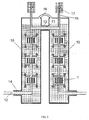
- FIG. 2 An example of such standardized modular current limiting device is shown in figure 2 wherein a plurality of current limiting units of the present invention are combined to form the desired current limiting device.
- the individual current limiting units are connected electrically in series by the supply tubes 6a, b which, simultaneously, serve to provide cooling medium to the interior of the current limiting units.
- two insulation housings 10 are coupled to each other via an upper docking site 13.
- the insulation housings 10 shown in figure 2 also comprise lower dockings sites 14 for coupling to further modular insulation housings (not shown).
- each insulation housing 10 The current limiting units in each insulation housing 10 are electrically connected by upper and lower electrical connection 11 and 12. Electrical connections 11 and 12, as the current supply 6 a, b, preferably have tubular shape for allowing communication of the cooling medium for the current limiting unit.
- Upper and lower electrical connection 12 are connected to current supply 6 a and 6 b.
- upper electrical connection 11 is connected to the upper end current supply 6 a of the upper end current limiting units of each of the insulation housings 10 coupled via upper docking site 13 and lower electrical connection 12 is connected to the lower end current supply 6 b of the lower end current limiting units of each of the insulation housings 10 coupled via lower docking site 14 (in figure 2 the further insulation housings coupled via lower docking site 12 are not shown).
- the individual modular insulation housings 10 form standardized modular components with the number being arranged in series being chosen according to need.
- the free electrical connection 11 or 12 (that is the electrical connection 11 or 12 which is not connected to a further module) can be used to connect the arrangement to an external grid.
- the respective docking site is tightly closed by a suitable, preferably releasable, closure.
- the endmost module can be modified by omitting the free electrical connection 11 and 12 and the respective docking sites and electrically connecting the arrangement to an external grid via the current supply 6 a and 6 b respectively, at the end of the series of modules 10 (free current supply).
- At least one discharge conduit 15 can be provided for discharging the gaseous cooling medium, i. e. the gas bubbles, from the first cooling circuit.
- the at least one discharge conduit 15 can be connected to the first cooling medium circuit at any suitable position.
- the discharge conduit is provided at a position on top of the first cooling medium circuit as shown in figure 2 .
- each modular insulation housing 10 is provided with a discharge conduit 15 wherein the discharge conduit 15 is connected to the upper end of the topmost supply 6a. Since the discharge conduit 15 is provided in a top position rising gas bubbles can be easily discharged.
- the discharge conduit 15 is made of an electrically non conductive material.
- the discharge conduit 15 is provided with an outlet 17 such as a valve or the like, which allows escape of the gaseous cooling medium but prevents access from the outside into the first cooling circuit.
- Cooling medium can be, for example, supplied to the first cooling medium circuit via electrical connection 12, 13 at any free end or via discharge conduit 15.
- the top level of the liquid cooling medium within the cryostat housing 10 shall extend at least to the upper end of upper docking site 13 to ensure cooling of the docket site and the electrical connection therein.
- the interior of adjacent modules 10 can be linked via a compensation tube 14 allowing compensation of liquid, pressure etc. between the individual modules 10.
- modules 10 which can be coupled to each other.
- a further advantage of the present invention is that the junction from one module 10 to the adjacent module 10 via the docking sites 13, 14 allows connection in the cooled state. Thus, any loss of thermal energy is avoided as occurs in cases wherein successive insulation housings are connected via a warm connection extending outside the cooled interior.
Landscapes
- Emergency Protection Circuit Devices (AREA)
- Containers, Films, And Cooling For Superconductive Devices (AREA)
Claims (11)
- Limiteur de courant de défaut comprenant au moins une unité de limitation de courant (1), dans lequel ladite au moins une unité de limitation de courant (1) est agencée à l'intérieur d'un logement isolant (9, 10) et dans lequel ladite au moins une unité de limitation de courant (1) comprend un ou plusieurs éléments supraconducteurs (2), dans lequel ladite au moins une unité de limitation de courant (1) forme un boîtier qui sépare spatialement les éléments supraconducteurs (2) de l'intérieur environnant du logement isolant (9, 10), dans lequel le limiteur de courant de défaut comprend un premier circuit de milieu de refroidissement pour refroidir les éléments supraconducteurs (2) dans l'unité de limitation de courant (1), caractérisé en ce que le limiteur de courant de défaut comprend en outre un deuxième circuit de milieu de refroidissement pour alimenter l'intérieur environnant du logement isolant (9, 10), et en ce que lesdits un ou plusieurs éléments supraconducteurs (2) sont connectés électriquement à des tubes d'alimentation en courant (6a, 6b) qui servent simultanément à délivrer et décharger le milieu de refroidissement vers et à partir de l'intérieur de ladite au moins une unité de limitation de courant (1).
- Limiteur de courant de défaut selon la revendication 1, dans lequel le boîtier de ladite au moins une unité de limitation de courant (1) est formé par une électrode de blindage (4) avec une face optionnellement laissée ouverte qui est fermée par un couvercle (5).
- Limiteur de courant de défaut selon la revendication 1 ou 2, dans lequel les éléments supraconducteurs (2) individuels sont maintenus par un support (3).
- Limiteur de courant de défaut selon la revendication 3, dans lequel les éléments supraconducteurs (2) individuels dans ladite au moins une unité de limitation de courant (1) sont connectés électriquement en parallèle.
- Limiteur de courant de défaut selon l'une quelconque des revendications précédentes, dans lequel les unités de limitation de courant (1) dans le logement isolant (9, 10) sont connectées électriquement en série par les tubes d'alimentation en courant (6a, 6b).
- Limiteur de courant de défaut selon l'une quelconque des revendications précédentes, dans lequel le logement isolant (9, 10) comprend au moins un site d'accueil (13, 14) approprié pour coupler le logement isolant (9, 10) à au moins un autre logement isolant (9, 10).
- Limiteur de courant de défaut selon les revendications précédentes, dans lequel les intérieurs des logements isolants (9, 10) successifs sont reliés physiquement par un tube de compensation (16) .
- Limiteur de courant de défaut selon l'une quelconque des revendications précédentes, dans lequel au moins un conduit (15) est relié au premier circuit de milieu de refroidissement pour permettre la décharge d'un milieu de refroidissement gazeux.
- Unité de limitation de courant (1) comprenant un ou plusieurs éléments supraconducteurs (2), dans laquelle l'unité de limitation de courant (1) forme un boîtier qui sépare spatialement les éléments supraconducteurs (2) de l'environnement, caractérisée en ce que, pour une connexion électrique à d'autres unités de limitation de courant (1) et/ou à une grille externe, lesdits un ou plusieurs éléments supraconducteurs (2) sont connectés à des tubes d'alimentation en courant (6a, 6b) qui servent simultanément à délivrer et décharger un milieu de refroidissement vers et à partir de l'intérieur de l'unité de limitation de courant (1).
- Unité de limitation de courant (1) selon la revendication 9, dans laquelle le boîtier est formé par une électrode de blindage (4) et dans laquelle une face optionnellement laissée ouverte est fermée par un couvercle (5).
- Utilisation d'un logement isolant (9, 10) et/ou d'une unité de limitation de courant (1) telle que définie dans la revendication 9 ou 10 dans une conception modulaire d'un limiteur de courant de défaut selon l'une quelconque des revendications 1 à 8.
Priority Applications (6)
| Application Number | Priority Date | Filing Date | Title |
|---|---|---|---|
| AT08305352T ATE477592T1 (de) | 2008-06-27 | 2008-06-27 | Strombegrenzungsvorrichtung |
| EP08305352A EP2139053B1 (fr) | 2008-06-27 | 2008-06-27 | Dispositif de limitation de courant |
| ES08305352T ES2350024T3 (es) | 2008-06-27 | 2008-06-27 | Dispositivo limitador de corriente. |
| DE602008002152T DE602008002152D1 (de) | 2008-06-27 | 2008-06-27 | Strombegrenzungsvorrichtung |
| JP2009139099A JP2010016368A (ja) | 2008-06-27 | 2009-06-10 | 限流器 |
| US12/489,051 US8264802B2 (en) | 2008-06-27 | 2009-06-22 | Current limiting device |
Applications Claiming Priority (1)
| Application Number | Priority Date | Filing Date | Title |
|---|---|---|---|
| EP08305352A EP2139053B1 (fr) | 2008-06-27 | 2008-06-27 | Dispositif de limitation de courant |
Publications (2)
| Publication Number | Publication Date |
|---|---|
| EP2139053A1 EP2139053A1 (fr) | 2009-12-30 |
| EP2139053B1 true EP2139053B1 (fr) | 2010-08-11 |
Family
ID=39773895
Family Applications (1)
| Application Number | Title | Priority Date | Filing Date |
|---|---|---|---|
| EP08305352A Not-in-force EP2139053B1 (fr) | 2008-06-27 | 2008-06-27 | Dispositif de limitation de courant |
Country Status (6)
| Country | Link |
|---|---|
| US (1) | US8264802B2 (fr) |
| EP (1) | EP2139053B1 (fr) |
| JP (1) | JP2010016368A (fr) |
| AT (1) | ATE477592T1 (fr) |
| DE (1) | DE602008002152D1 (fr) |
| ES (1) | ES2350024T3 (fr) |
Families Citing this family (2)
| Publication number | Priority date | Publication date | Assignee | Title |
|---|---|---|---|---|
| SG195087A1 (en) * | 2011-05-24 | 2013-12-30 | Furukawa Electric Co Ltd | Superconducting element for superconducting current limiter, method for manufacturing superconducting element for superconducting current limiter, and superconducting current limiter |
| WO2012165504A1 (fr) * | 2011-05-31 | 2012-12-06 | 古河電気工業株式会社 | Film mince de supraconducteur d'oxyde, limiteur de courant de défaut supraconducteur et procédé de fabrication d'un film mince de supraconducteur d'oxyde |
Family Cites Families (6)
| Publication number | Priority date | Publication date | Assignee | Title |
|---|---|---|---|---|
| JP2895616B2 (ja) * | 1990-11-26 | 1999-05-24 | 古河電気工業株式会社 | 定格電流可変型超電導限流器 |
| DE19520205A1 (de) * | 1995-06-01 | 1996-12-05 | Siemens Ag | Resistive Strombegrenzungseinrichtung unter Verwendung von Hoch-T¶c¶Supraleitermaterial |
| EP1217708A1 (fr) * | 2000-12-21 | 2002-06-26 | Abb Research Ltd. | Dispositif supraconducteur |
| JP4193024B2 (ja) | 2001-11-19 | 2008-12-10 | 株式会社イノアックコーポレーション | リタードローラおよびその製造方法 |
| GB0315663D0 (en) * | 2003-07-04 | 2003-08-13 | Rolls Royce Plc | A fault current limiter |
| US7484372B2 (en) * | 2006-03-06 | 2009-02-03 | Linde, Inc. | Multi-bath apparatus and method for cooling superconductors |
-
2008
- 2008-06-27 DE DE602008002152T patent/DE602008002152D1/de active Active
- 2008-06-27 ES ES08305352T patent/ES2350024T3/es active Active
- 2008-06-27 EP EP08305352A patent/EP2139053B1/fr not_active Not-in-force
- 2008-06-27 AT AT08305352T patent/ATE477592T1/de not_active IP Right Cessation
-
2009
- 2009-06-10 JP JP2009139099A patent/JP2010016368A/ja not_active Withdrawn
- 2009-06-22 US US12/489,051 patent/US8264802B2/en not_active Expired - Fee Related
Also Published As
| Publication number | Publication date |
|---|---|
| ATE477592T1 (de) | 2010-08-15 |
| JP2010016368A (ja) | 2010-01-21 |
| US8264802B2 (en) | 2012-09-11 |
| US20100157499A1 (en) | 2010-06-24 |
| ES2350024T3 (es) | 2011-01-17 |
| EP2139053A1 (fr) | 2009-12-30 |
| DE602008002152D1 (de) | 2010-09-23 |
Similar Documents
| Publication | Publication Date | Title |
|---|---|---|
| US11488747B2 (en) | Superconducting power cable system | |
| US4994932A (en) | Superconducting current limiting apparatus | |
| DE102007013350B4 (de) | Stromzuführung mit Hochtemperatursupraleitern für supraleitende Magnete in einem Kryostaten | |
| CN107646158B (zh) | 超导故障电流限制器系统及适用于超导带的连接系统 | |
| JP5687548B2 (ja) | 超伝導ケーブルを備える装置 | |
| JPH09190847A (ja) | 超電導多相ケーブルを室温の電気装置に接続する端子 | |
| JP5190211B2 (ja) | 抵抗型限流器 | |
| JPH04321284A (ja) | クライオスタットの蒸気冷却電力リード | |
| JP2012217334A (ja) | 極低温ケーブルの終端接続部 | |
| CN108879017A (zh) | 能量存储装置 | |
| EP3218909A1 (fr) | Échangeurs de chaleur à ailettes et à mousses avec changement de phase pour stockage d'énergie thermique cryogénique et limiteurs de courant de défaut | |
| EP2139053B1 (fr) | Dispositif de limitation de courant | |
| WO2019146269A1 (fr) | Câble supraconducteur | |
| EP3370239B1 (fr) | Borne de câble supraconducteur | |
| KR101620495B1 (ko) | 전류 제한 장치 | |
| GB2162712A (en) | Electrical switch | |
| US7531750B2 (en) | Power supply line for cryogenic electrical systems | |
| KR101224214B1 (ko) | 실온 상태의 장치와 초전도 장치를 연결하기 위한 전기피드스루 | |
| EP1133794A1 (fr) | Element de refroidissement et procede de fabrication d'un element de refroidissement con u pour refroidir au moins un composant electrique | |
| de Souza et al. | Development and testing of joints in high temperature superconducting power cable | |
| EP4447282A1 (fr) | Appareil | |
| JP2013143474A (ja) | 超電導マグネット装置及びその電流リード | |
| JPH1012058A (ja) | 超電導送電ケーブル | |
| JP2008130860A (ja) | 超電導装置および電流リード |
Legal Events
| Date | Code | Title | Description |
|---|---|---|---|
| PUAI | Public reference made under article 153(3) epc to a published international application that has entered the european phase |
Free format text: ORIGINAL CODE: 0009012 |
|
| 17P | Request for examination filed |
Effective date: 20080627 |
|
| AK | Designated contracting states |
Kind code of ref document: A1 Designated state(s): AT BE BG CH CY CZ DE DK EE ES FI FR GB GR HR HU IE IS IT LI LT LU LV MC MT NL NO PL PT RO SE SI SK TR |
|
| AX | Request for extension of the european patent |
Extension state: AL BA MK RS |
|
| GRAP | Despatch of communication of intention to grant a patent |
Free format text: ORIGINAL CODE: EPIDOSNIGR1 |
|
| GRAS | Grant fee paid |
Free format text: ORIGINAL CODE: EPIDOSNIGR3 |
|
| GRAA | (expected) grant |
Free format text: ORIGINAL CODE: 0009210 |
|
| AK | Designated contracting states |
Kind code of ref document: B1 Designated state(s): AT BE BG CH CY CZ DE DK EE ES FI FR GB GR HR HU IE IS IT LI LT LU LV MC MT NL NO PL PT RO SE SI SK TR |
|
| REG | Reference to a national code |
Ref country code: GB Ref legal event code: FG4D |
|
| REG | Reference to a national code |
Ref country code: CH Ref legal event code: EP |
|
| AKX | Designation fees paid |
Designated state(s): AT BE BG CH CY CZ DE DK EE ES FI FR GB GR HR HU IE IS IT LI LT LU LV MC MT NL NO PL PT RO SE SI SK TR |
|
| REG | Reference to a national code |
Ref country code: IE Ref legal event code: FG4D |
|
| REF | Corresponds to: |
Ref document number: 602008002152 Country of ref document: DE Date of ref document: 20100923 Kind code of ref document: P |
|
| REG | Reference to a national code |
Ref country code: SE Ref legal event code: TRGR |
|
| REG | Reference to a national code |
Ref country code: NL Ref legal event code: VDEP Effective date: 20100811 |
|
| REG | Reference to a national code |
Ref country code: ES Ref legal event code: FG2A Effective date: 20110104 |
|
| LTIE | Lt: invalidation of european patent or patent extension |
Effective date: 20100811 |
|
| PG25 | Lapsed in a contracting state [announced via postgrant information from national office to epo] |
Ref country code: NO Free format text: LAPSE BECAUSE OF FAILURE TO SUBMIT A TRANSLATION OF THE DESCRIPTION OR TO PAY THE FEE WITHIN THE PRESCRIBED TIME-LIMIT Effective date: 20101111 Ref country code: AT Free format text: LAPSE BECAUSE OF FAILURE TO SUBMIT A TRANSLATION OF THE DESCRIPTION OR TO PAY THE FEE WITHIN THE PRESCRIBED TIME-LIMIT Effective date: 20100811 Ref country code: FI Free format text: LAPSE BECAUSE OF FAILURE TO SUBMIT A TRANSLATION OF THE DESCRIPTION OR TO PAY THE FEE WITHIN THE PRESCRIBED TIME-LIMIT Effective date: 20100811 Ref country code: LT Free format text: LAPSE BECAUSE OF FAILURE TO SUBMIT A TRANSLATION OF THE DESCRIPTION OR TO PAY THE FEE WITHIN THE PRESCRIBED TIME-LIMIT Effective date: 20100811 Ref country code: NL Free format text: LAPSE BECAUSE OF FAILURE TO SUBMIT A TRANSLATION OF THE DESCRIPTION OR TO PAY THE FEE WITHIN THE PRESCRIBED TIME-LIMIT Effective date: 20100811 |
|
| PG25 | Lapsed in a contracting state [announced via postgrant information from national office to epo] |
Ref country code: CY Free format text: LAPSE BECAUSE OF FAILURE TO SUBMIT A TRANSLATION OF THE DESCRIPTION OR TO PAY THE FEE WITHIN THE PRESCRIBED TIME-LIMIT Effective date: 20100811 Ref country code: HR Free format text: LAPSE BECAUSE OF FAILURE TO SUBMIT A TRANSLATION OF THE DESCRIPTION OR TO PAY THE FEE WITHIN THE PRESCRIBED TIME-LIMIT Effective date: 20100811 Ref country code: IS Free format text: LAPSE BECAUSE OF FAILURE TO SUBMIT A TRANSLATION OF THE DESCRIPTION OR TO PAY THE FEE WITHIN THE PRESCRIBED TIME-LIMIT Effective date: 20101211 Ref country code: PL Free format text: LAPSE BECAUSE OF FAILURE TO SUBMIT A TRANSLATION OF THE DESCRIPTION OR TO PAY THE FEE WITHIN THE PRESCRIBED TIME-LIMIT Effective date: 20100811 Ref country code: SI Free format text: LAPSE BECAUSE OF FAILURE TO SUBMIT A TRANSLATION OF THE DESCRIPTION OR TO PAY THE FEE WITHIN THE PRESCRIBED TIME-LIMIT Effective date: 20100811 Ref country code: BG Free format text: LAPSE BECAUSE OF FAILURE TO SUBMIT A TRANSLATION OF THE DESCRIPTION OR TO PAY THE FEE WITHIN THE PRESCRIBED TIME-LIMIT Effective date: 20101111 |
|
| RAP2 | Party data changed (patent owner data changed or rights of a patent transferred) |
Owner name: NEXANS |
|
| PG25 | Lapsed in a contracting state [announced via postgrant information from national office to epo] |
Ref country code: GR Free format text: LAPSE BECAUSE OF FAILURE TO SUBMIT A TRANSLATION OF THE DESCRIPTION OR TO PAY THE FEE WITHIN THE PRESCRIBED TIME-LIMIT Effective date: 20101112 Ref country code: LV Free format text: LAPSE BECAUSE OF FAILURE TO SUBMIT A TRANSLATION OF THE DESCRIPTION OR TO PAY THE FEE WITHIN THE PRESCRIBED TIME-LIMIT Effective date: 20100811 Ref country code: BE Free format text: LAPSE BECAUSE OF FAILURE TO SUBMIT A TRANSLATION OF THE DESCRIPTION OR TO PAY THE FEE WITHIN THE PRESCRIBED TIME-LIMIT Effective date: 20100811 |
|
| PG25 | Lapsed in a contracting state [announced via postgrant information from national office to epo] |
Ref country code: DK Free format text: LAPSE BECAUSE OF FAILURE TO SUBMIT A TRANSLATION OF THE DESCRIPTION OR TO PAY THE FEE WITHIN THE PRESCRIBED TIME-LIMIT Effective date: 20100811 |
|
| PG25 | Lapsed in a contracting state [announced via postgrant information from national office to epo] |
Ref country code: SK Free format text: LAPSE BECAUSE OF FAILURE TO SUBMIT A TRANSLATION OF THE DESCRIPTION OR TO PAY THE FEE WITHIN THE PRESCRIBED TIME-LIMIT Effective date: 20100811 Ref country code: EE Free format text: LAPSE BECAUSE OF FAILURE TO SUBMIT A TRANSLATION OF THE DESCRIPTION OR TO PAY THE FEE WITHIN THE PRESCRIBED TIME-LIMIT Effective date: 20100811 Ref country code: CZ Free format text: LAPSE BECAUSE OF FAILURE TO SUBMIT A TRANSLATION OF THE DESCRIPTION OR TO PAY THE FEE WITHIN THE PRESCRIBED TIME-LIMIT Effective date: 20100811 Ref country code: RO Free format text: LAPSE BECAUSE OF FAILURE TO SUBMIT A TRANSLATION OF THE DESCRIPTION OR TO PAY THE FEE WITHIN THE PRESCRIBED TIME-LIMIT Effective date: 20100811 |
|
| PLBE | No opposition filed within time limit |
Free format text: ORIGINAL CODE: 0009261 |
|
| STAA | Information on the status of an ep patent application or granted ep patent |
Free format text: STATUS: NO OPPOSITION FILED WITHIN TIME LIMIT |
|
| 26N | No opposition filed |
Effective date: 20110512 |
|
| PGFP | Annual fee paid to national office [announced via postgrant information from national office to epo] |
Ref country code: SE Payment date: 20110613 Year of fee payment: 4 |
|
| REG | Reference to a national code |
Ref country code: DE Ref legal event code: R097 Ref document number: 602008002152 Country of ref document: DE Effective date: 20110512 |
|
| PG25 | Lapsed in a contracting state [announced via postgrant information from national office to epo] |
Ref country code: MT Free format text: LAPSE BECAUSE OF FAILURE TO SUBMIT A TRANSLATION OF THE DESCRIPTION OR TO PAY THE FEE WITHIN THE PRESCRIBED TIME-LIMIT Effective date: 20100811 |
|
| PGFP | Annual fee paid to national office [announced via postgrant information from national office to epo] |
Ref country code: IT Payment date: 20110630 Year of fee payment: 4 |
|
| REG | Reference to a national code |
Ref country code: IE Ref legal event code: MM4A |
|
| PG25 | Lapsed in a contracting state [announced via postgrant information from national office to epo] |
Ref country code: IE Free format text: LAPSE BECAUSE OF NON-PAYMENT OF DUE FEES Effective date: 20110627 |
|
| PGFP | Annual fee paid to national office [announced via postgrant information from national office to epo] |
Ref country code: ES Payment date: 20120627 Year of fee payment: 5 |
|
| REG | Reference to a national code |
Ref country code: SE Ref legal event code: EUG |
|
| REG | Reference to a national code |
Ref country code: CH Ref legal event code: PL |
|
| REG | Reference to a national code |
Ref country code: CH Ref legal event code: PL |
|
| PG25 | Lapsed in a contracting state [announced via postgrant information from national office to epo] |
Ref country code: SE Free format text: LAPSE BECAUSE OF NON-PAYMENT OF DUE FEES Effective date: 20120628 Ref country code: IT Free format text: LAPSE BECAUSE OF NON-PAYMENT OF DUE FEES Effective date: 20120627 |
|
| PG25 | Lapsed in a contracting state [announced via postgrant information from national office to epo] |
Ref country code: CH Free format text: LAPSE BECAUSE OF NON-PAYMENT OF DUE FEES Effective date: 20120630 Ref country code: LI Free format text: LAPSE BECAUSE OF NON-PAYMENT OF DUE FEES Effective date: 20120630 Ref country code: MC Free format text: LAPSE BECAUSE OF NON-PAYMENT OF DUE FEES Effective date: 20110630 |
|
| PG25 | Lapsed in a contracting state [announced via postgrant information from national office to epo] |
Ref country code: LU Free format text: LAPSE BECAUSE OF NON-PAYMENT OF DUE FEES Effective date: 20110627 |
|
| PG25 | Lapsed in a contracting state [announced via postgrant information from national office to epo] |
Ref country code: TR Free format text: LAPSE BECAUSE OF FAILURE TO SUBMIT A TRANSLATION OF THE DESCRIPTION OR TO PAY THE FEE WITHIN THE PRESCRIBED TIME-LIMIT Effective date: 20100811 |
|
| PG25 | Lapsed in a contracting state [announced via postgrant information from national office to epo] |
Ref country code: HU Free format text: LAPSE BECAUSE OF FAILURE TO SUBMIT A TRANSLATION OF THE DESCRIPTION OR TO PAY THE FEE WITHIN THE PRESCRIBED TIME-LIMIT Effective date: 20100811 |
|
| REG | Reference to a national code |
Ref country code: ES Ref legal event code: FD2A Effective date: 20140707 |
|
| PG25 | Lapsed in a contracting state [announced via postgrant information from national office to epo] |
Ref country code: PT Free format text: LAPSE BECAUSE OF FAILURE TO SUBMIT A TRANSLATION OF THE DESCRIPTION OR TO PAY THE FEE WITHIN THE PRESCRIBED TIME-LIMIT Effective date: 20100811 |
|
| PG25 | Lapsed in a contracting state [announced via postgrant information from national office to epo] |
Ref country code: ES Free format text: LAPSE BECAUSE OF NON-PAYMENT OF DUE FEES Effective date: 20130628 |
|
| REG | Reference to a national code |
Ref country code: FR Ref legal event code: PLFP Year of fee payment: 9 |
|
| REG | Reference to a national code |
Ref country code: FR Ref legal event code: PLFP Year of fee payment: 10 |
|
| REG | Reference to a national code |
Ref country code: FR Ref legal event code: PLFP Year of fee payment: 11 |
|
| PGFP | Annual fee paid to national office [announced via postgrant information from national office to epo] |
Ref country code: DE Payment date: 20180625 Year of fee payment: 11 |
|
| PGFP | Annual fee paid to national office [announced via postgrant information from national office to epo] |
Ref country code: FR Payment date: 20180620 Year of fee payment: 11 |
|
| PGFP | Annual fee paid to national office [announced via postgrant information from national office to epo] |
Ref country code: GB Payment date: 20180620 Year of fee payment: 11 |
|
| REG | Reference to a national code |
Ref country code: DE Ref legal event code: R119 Ref document number: 602008002152 Country of ref document: DE |
|
| GBPC | Gb: european patent ceased through non-payment of renewal fee |
Effective date: 20190627 |
|
| PG25 | Lapsed in a contracting state [announced via postgrant information from national office to epo] |
Ref country code: DE Free format text: LAPSE BECAUSE OF NON-PAYMENT OF DUE FEES Effective date: 20200101 Ref country code: GB Free format text: LAPSE BECAUSE OF NON-PAYMENT OF DUE FEES Effective date: 20190627 |
|
| PG25 | Lapsed in a contracting state [announced via postgrant information from national office to epo] |
Ref country code: FR Free format text: LAPSE BECAUSE OF NON-PAYMENT OF DUE FEES Effective date: 20190630 |