EP2138780A2 - Wärmepistole - Google Patents
Wärmepistole Download PDFInfo
- Publication number
- EP2138780A2 EP2138780A2 EP09162709A EP09162709A EP2138780A2 EP 2138780 A2 EP2138780 A2 EP 2138780A2 EP 09162709 A EP09162709 A EP 09162709A EP 09162709 A EP09162709 A EP 09162709A EP 2138780 A2 EP2138780 A2 EP 2138780A2
- Authority
- EP
- European Patent Office
- Prior art keywords
- heat gun
- arm
- handle
- extended position
- nozzle
- Prior art date
- Legal status (The legal status is an assumption and is not a legal conclusion. Google has not performed a legal analysis and makes no representation as to the accuracy of the status listed.)
- Granted
Links
Images




Classifications
-
- F—MECHANICAL ENGINEERING; LIGHTING; HEATING; WEAPONS; BLASTING
- F24—HEATING; RANGES; VENTILATING
- F24H—FLUID HEATERS, e.g. WATER OR AIR HEATERS, HAVING HEAT-GENERATING MEANS, e.g. HEAT PUMPS, IN GENERAL
- F24H3/00—Air heaters
- F24H3/02—Air heaters with forced circulation
- F24H3/04—Air heaters with forced circulation the air being in direct contact with the heating medium, e.g. electric heating element
- F24H3/0405—Air heaters with forced circulation the air being in direct contact with the heating medium, e.g. electric heating element using electric energy supply, e.g. the heating medium being a resistive element; Heating by direct contact, i.e. with resistive elements, electrodes and fins being bonded together without additional element in-between
- F24H3/0423—Air heaters with forced circulation the air being in direct contact with the heating medium, e.g. electric heating element using electric energy supply, e.g. the heating medium being a resistive element; Heating by direct contact, i.e. with resistive elements, electrodes and fins being bonded together without additional element in-between hand-held air guns
Definitions
- the present invention relates to a heat gun.
- a heat gun is a device which generates a flow of hot air for use in a variety of applications.
- a heat gun comprises a tubular body in which is located a fan. Air is drawn in at one end of the body by the operation of the fan and is blown out of the other end through a nozzle, after having passed over a heating element also located within the body which heats up the air as it passes over/ or through the heating element.
- the hot air is typically expelled from the body through a metal nozzle.
- the problem with such a design is that the nozzle can become extremely hot. Therefore, when an operator has finished using the heat gun, the heat gun can not be simply placed on its side on a work surface as the heat from the nozzle can damage the work surface, at least until the nozzle has cooled. Therefore, the heat gun has to be either placed on a surface which is capable of with standing the heat or on a surface where there is no concern if it becomes damaged. Even if it is acceptable for damage to the surface to occur, the operator must ensure that the damage caused to the surface does not have an impact on the heat gun; for example, if it were made of plastic, it would not desirable for the plastic to become melted onto the nozzle.
- the heat gun can be placed on a surface in such a manner that the nozzle is located away from the work surface.
- One way of achieving this is to balance the heat gun on the work surface, assuming the shape of the heat gun provides suitable support for it to be balanced in such a manner.
- this provides either a heat gun which is unstable which can easily be knocked over or a heat gun which has a non desirable shape. Furthermore, the instability is increased if the surface is not flat or is at an angle.
- US 2003 0235462 provides a heat gun having a support mechanism which improves the stability of the heat gun when placed on a work surface.
- the support mechanism is located on the base of the heat gun. This restricts the use of the base in providing air vents for the provision of air to operate the heat gun.
- the use of slidable wings provides a weak construction, and are liable to break during use. Furthermore, the wings need to slide in grooves which tend to clog up during the use of such a heat gun.
- a heat gun comprising:
- the present invention provides a mechanism by an air gun can be placed on a surface so that the nozzle does not come into contact with the surface in a stable manner. Furthermore, the mechanism can be retracted so that, when the heat gun is in use, it does not interfere with the operation of the heat gun. Furthermore, it provides a robust design of support mechanism which does not interfere with the base..
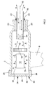
- the heat gun comprises a tubular body 2.
- the passageway 4 formed by the body 2 runs the length of the body (see Figure 2 ).
- Attached to the side of the body is a D shaped handle 6 having a grip portion 8.
- the handle, particularly the grip portion extends in a generally perpendicular direction to a longitudinal axis 18 of the body 2.
- an electric motor 10 which, when activated, rotatingly drives a fan 12 mounted on its spindle 14 within the passageway 4.
- a metal tubular nozzle 16 Mounted on the front of the body 2 is a metal tubular nozzle 16, the longitudinal axis 18 of the nozzle being generally parallel to and co-axial with that of the passageway 4.
- a plastic guard 20 which surrounds part of the length of the nozzle 16 as shown, but which creates a gap 22 between the guard 20 and the nozzle 16.
- the guard 16 limits the amount of nozzle 16 exposed to the operator and thus reduces the risk of the operator touching the nozzle 16 when it is hot. Nevertheless, the end of the nozzle 16 extends beyond the end of the guard 20.
- the gap 22 prevents the guard 20 from melting due to the heat from the nozzle 16.
- the heating device 24 comprises electric heating elements which heat up when an electric current passes through them. Air is capable of flowing through and/or over the heating elements of the heating device 24. The heating device 24 heats up any air which passes over and/or through the heating device 24 when it is activated by an electric current.
- a base 26 Mounted on the rear of the body 2 is a base 26 which has a number of vents 32 formed through it.
- An electric cable 30 connects to the motor 10 and heating device 24 via a toggle switch 28.
- the electric cable 30 connects to an electrical AC power source. Depression of the toggle switch 28 provides an electric current to the motor 10 and the heating device 24.
- the electric motor 10 rotates, rotatingly driving the fan 12, and the heating device becomes hot.
- Rotation of the fan 12 causes air to be drawn in through the vents 32 in base 26, across the motor 10, through the fan 12, over and/or through the heating device 24 where it is heated to a high temperature, and then through the nozzle 16 where it is expelled forward, as indicated by Arrows A, in Figure 2 .
- Additional vents 34 are formed in the side wall of the body 2 immediately rearward and forward of the motor 10 through which air can also be drawn into the body 2. When the heat gun is running, the nozzle 16 becomes very hot due to the hot air being blown through it.
- the base 26 is provided with a flat rear surface 38.
- a stop 40 having a flat surface 42, is formed on the lower end 56 of the handle 6, below the grip 8.
- the heat gun can be supported on to the work surface 36 by the being balanced on the flat surface 38 of the base 26 and the flat surface 42 of the stop 40 as shown in Figure 1 .
- this is unstable and the heat gun can easily be knocked over.
- the instability is increased if the surface 36 is not flat or is at an angle. Therefore the heat gun has a support mechanism which will be described in further detail below.
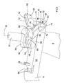
- the support mechanism comprises two pivot arms 50; 52 which are pivotally mounted on a circular stump 54 formed on the lower end 56 of the handle 6 remote from the base as shown in Figure 4 .
- the circular stump 54 comprises a middle section 58 of uniform circular cross section and a radial flange 60 attached to the end of the middle section 58 remote from the lower end 56 of the handle 6.
- Each pivotal arm 50; 52 comprises two circular arms 62 which have an inner diameter approximately equal to that of the middle section 58 of the stump 54.
- a gap is formed between the ends 64 of the circular arms 62.
- the circular arms 62 of each pivotal arm 50;52 wrap around the middle section 58 of the stump 54.
- the circular arms 62 of one pivotal arm 50 is located by the side of and adjacent to, in the lengthwise direction of the stump 54, the circular arms 62 of the other pivotal arm 52 on the middle section 58, as shown in Figures 4 , 6 , 8 and 9 .
- the radial flange 60 prevents the radial arms 62 from sliding off the stump 54.
- the circular arms 62 are flexible so that, when the heat gun is manufactured, the middle section 58 can be prized through the gap formed by the ends 64 of the circular arms 62; the gap increasing to allow the middle section 58 to pass through it due to the circular arms 62 flexing.
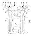
- the construction of the two pivotal arms 50; 52 and their respective circular arms 62 vary relative to each other so that, even though the circular arms 62 of each pivotal arm 50; 52 are located side by side in the lengthwise direction of the stump 54, adjacent each other on the middle section 58 as shown in Figures 4 , 6 , 8 and 9 , the two pivotal arms are located at the same position, in the lengthwise direction of the stump 54, along the middle section 58, as best seen in Figure 6 .
- the pivotal arms 50; 52 pivot within the same plane which plane is perpendicular about the longitudinal axis 61 of the stump 54.
- the circular arms 62, and hence the pivotal arms 50; 52 can freely pivot on the middle section 58 of the stump 54.
- the pivotal movement of each pivotal arm 50; 52 is independent of the pivotal movement of the other pivotal arm.
- Each pivotal arm 50; 52 can pivotal from a retracted position (both pivotal arms are shown their retracted positions in Figure 6 ) to an extended position (both pivotal arms are shown their extended position in Figure 5 ).
- each arm 50; 52 In the retracted position, the outer side 66 of each arm 50; 52 is flush with the sides of the lower end 56 of the handle 6. When both pivotal arms 50; 52 are retracted, they are parallel to each other and parallel with longitudinal axis 18 of the body 2.
- the retracted position of each pivotal arm 50; 52 is determined by a peg 68 formed on the underside of the lower end 56 of the handle 6. When each arm 50; 52 is in its retracted position, it abuts against its respective peg 68 as shown in Figure 6 .
- each arm 50; 52 In the extended position, each arm 50; 52 extends outwardly at an angle in rearward direction as shown in Figure 5 .
- both pivotal arms 50; 52 When both pivotal arms 50; 52 are extended, they are symmetrical to each other.
- the extended position of each pivotal arm is determined by a abutment surface 70 formed on the stop 40 as best seen in Figure 9 .
- each pivotal arm 50; 52 When each pivotal arm 50; 52 is in its extended position, it abuts against its respective abutment surface 70.
- each pivotal arm 50; 52 Formed around the edges of the top surfaces 74 each pivotal arm 50; 52 is a ridge 72. Formed on each side of the stop 40 adjacent the abutment surface 70 is a protrusion 76 as best seen in Figure 9 .
- the ridge 72 of each arm 50; 52 engages with the protrusion 76 which then rides over the ridge 72 due to it being slightly flexible, and engages with the inner side of the ridge 72 as shown in Figure 7 to hold the pivotal arm 50; 52 in its extended position.
- each pivotal arm 50; 52 Formed on bottom surface of each pivotal arm 50; 52, at the end of the pivotal arms 50; 52 is a second protrusion 78. Formed on the under side of the lower section 56 are two corresponding engagement ridges 80 as best seen in Figure 4 .
- the second protrusion 78 of each arm 50; 52 engages with the engagement ridge 80 which then rides over the engagement ridge 80 due to being slightly flexible, and engages with the inner side of the engagement ridge 80 to hold the pivotal arm 50; 52 in its retracted position.
- the two pivotal arms are moved to their respective retracted position as shown in Figure 6 .
- the operator needs to place it on a work surface so that the nozzle, which is hot is located away from the work surface.
- the operator moves the pivotal arms 50; 52 from their retracted positions to their extended positions, locking the arms 50; 52 in the extended positions with the protrusions 76 and ridges.
- the operator can then place the heat gun on the work surface 36, the flat surface 38 of the base 26, the flat surface 42 of the stop 40 and angled surfaces 82 formed on each arm 50; 52 forming a platform which engages with the work surface 36 as best seen in Figure 5 .
- the flat surface 38 of the base 26, the flat surface 42 of the stop 40 and the angled surfaces 82 formed on each arm 50; 52 are located within the same plane.
- the use of the two pivotal arms 50; 52 provides greater stability to the heat gun on the work surface whilst the nozzle cools. Once cool, the operator can move the arms 50; 52 into their retracted positions where there will be held by the engagement ridges 80 and second protrusions 78. The operator can then hang the heat gun on a hook using a loop 90 mounted on the electric cable 30.
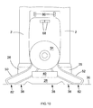
- a second embodiment of the present invention will now be described with reference to Figure 10 . Where the same features in the second embodiment are present in the first, the same reference numbers have been used.
- the second embodiment is the same as the first except that the stop 40 does not have a flat surface 42 or any surface which engages the work surface 36.
- the flat surface 38 of the base 26 and the angled surfaces 82 of the two pivotal arms 50; 52 only form a platform which engages with the work surface 36. As there are only three points of contact, a stable base will be provided even if the surface is not flat.
Landscapes
- Engineering & Computer Science (AREA)
- Physics & Mathematics (AREA)
- Thermal Sciences (AREA)
- Chemical & Material Sciences (AREA)
- Combustion & Propulsion (AREA)
- Mechanical Engineering (AREA)
- General Engineering & Computer Science (AREA)
- Toys (AREA)
- Coating Apparatus (AREA)
- Straightening Metal Sheet-Like Bodies (AREA)
Applications Claiming Priority (1)
| Application Number | Priority Date | Filing Date | Title |
|---|---|---|---|
| GBGB0811724.4A GB0811724D0 (en) | 2008-06-26 | 2008-06-26 | Heat gun |
Publications (3)
| Publication Number | Publication Date |
|---|---|
| EP2138780A2 true EP2138780A2 (de) | 2009-12-30 |
| EP2138780A3 EP2138780A3 (de) | 2013-12-04 |
| EP2138780B1 EP2138780B1 (de) | 2016-03-23 |
Family
ID=39683206
Family Applications (1)
| Application Number | Title | Priority Date | Filing Date |
|---|---|---|---|
| EP09162709.1A Not-in-force EP2138780B1 (de) | 2008-06-26 | 2009-06-15 | Wärmepistole |
Country Status (4)
| Country | Link |
|---|---|
| US (1) | US7982163B2 (de) |
| EP (1) | EP2138780B1 (de) |
| CN (1) | CN101614441B (de) |
| GB (1) | GB0811724D0 (de) |
Families Citing this family (40)
| Publication number | Priority date | Publication date | Assignee | Title |
|---|---|---|---|---|
| US8463115B1 (en) * | 2005-05-18 | 2013-06-11 | Judco Manufacturing, Inc. | Handheld heater |
| US20130209076A1 (en) * | 2005-05-18 | 2013-08-15 | Judco Manufacturing, Inc. | Handheld heater |
| US9635713B2 (en) | 2005-05-18 | 2017-04-25 | Judco Manufacturing, Inc. | Cordless handheld heater |
| CN102003795B (zh) * | 2010-09-28 | 2013-01-16 | 上海中科深江电动车辆有限公司 | 一种热风枪喷嘴结构、相关热风枪及应用 |
| USD679561S1 (en) * | 2011-03-24 | 2013-04-09 | Richard Price | Heat gun |
| GB201205687D0 (en) | 2012-03-30 | 2012-05-16 | Dyson Technology Ltd | A hand held appliance |
| GB201205683D0 (en) | 2012-03-30 | 2012-05-16 | Dyson Technology Ltd | A hand held appliance |
| GB201205695D0 (en) | 2012-03-30 | 2012-05-16 | Dyson Technology Ltd | Hand held appliance |
| GB201205690D0 (en) | 2012-03-30 | 2012-05-16 | Dyson Technology Ltd | A hand held appliance |
| GB201205679D0 (en) | 2012-03-30 | 2012-05-16 | Dyson Technology Ltd | A hand held appliance |
| MX2014011845A (es) | 2012-03-30 | 2014-12-10 | Dyson Technology Ltd | Un aparato electrico manual. |
| US10046894B1 (en) * | 2012-05-24 | 2018-08-14 | Milton Carter | Variable speed heat air gun and cooperating kit |
| US8942550B1 (en) * | 2012-05-24 | 2015-01-27 | Milton Carter | Variable speed heat air gun and cooperating kit |
| GB2503687B (en) | 2012-07-04 | 2018-02-21 | Dyson Technology Ltd | An attachment for a hand held appliance |
| EP2869726B1 (de) | 2012-07-04 | 2020-04-01 | Dyson Technology Limited | Haartrockner mit einer befestigung |
| GB2515810B (en) | 2013-07-05 | 2015-11-11 | Dyson Technology Ltd | A hand held appliance |
| GB2515809B (en) | 2013-07-05 | 2015-08-19 | Dyson Technology Ltd | A handheld appliance |
| GB2515808B (en) | 2013-07-05 | 2015-12-23 | Dyson Technology Ltd | A handheld appliance |
| GB2515813B (en) | 2013-07-05 | 2017-07-05 | Dyson Technology Ltd | A handheld appliance |
| KR101964103B1 (ko) | 2013-07-05 | 2019-04-01 | 다이슨 테크놀러지 리미티드 | 휴대형 전기기구 |
| GB2515811B (en) | 2013-07-05 | 2015-11-11 | Dyson Technology Ltd | A handheld appliance |
| GB2515815B (en) | 2013-07-05 | 2015-12-02 | Dyson Technology Ltd | A hand held appliance |
| GB2531431B (en) | 2013-07-24 | 2016-11-02 | Dyson Technology Ltd | An attachment for a handheld appliance |
| AU355723S (en) | 2013-09-26 | 2014-05-23 | Dyson Technology Ltd | A hair dryer |
| GB2518639B (en) | 2013-09-26 | 2016-03-09 | Dyson Technology Ltd | A hand held appliance |
| AU355721S (en) | 2013-09-26 | 2014-05-23 | Dyson Technology Ltd | A hair dryer |
| AU355722S (en) | 2013-09-26 | 2014-05-23 | Dyson Technology Ltd | A hair dryer |
| GB2518656B (en) | 2013-09-27 | 2016-04-13 | Dyson Technology Ltd | Hand held appliance |
| USD743016S1 (en) * | 2014-02-06 | 2015-11-10 | Leister Technologies Ag | Hot air device |
| AU363171S (en) | 2015-01-12 | 2015-08-06 | Dyson Technology Ltd | A hair appliance |
| CN204397850U (zh) * | 2015-01-14 | 2015-06-17 | 浙江普莱得电器有限公司 | 一种方便切换的多功能工具 |
| GB2534379B (en) | 2015-01-21 | 2018-05-09 | Dyson Technology Ltd | An attachment for a hand held appliance |
| GB2534378B (en) | 2015-01-21 | 2018-07-25 | Dyson Technology Ltd | An attachment for a hand held appliance |
| USD803649S1 (en) * | 2015-12-14 | 2017-11-28 | Wagner Spraytech (UK) Ltd. | Heat gun |
| USD835961S1 (en) * | 2017-03-06 | 2018-12-18 | Milwaukee Electric Tool Corporation | Power tool |
| USD867842S1 (en) * | 2018-04-25 | 2019-11-26 | Leister Technologies Ag | Hot air gun |
| USD868554S1 (en) * | 2018-10-03 | 2019-12-03 | Leister Technologies Ag | Hot air gun |
| USD947631S1 (en) * | 2019-12-26 | 2022-04-05 | Zhejiang Prulde Electric Appliance Co., Ltd. | Heat gun |
| USD946709S1 (en) * | 2020-05-08 | 2022-03-22 | Lutz Pumpen Gmbh | Dispenser gun |
| EP4671637B1 (de) * | 2024-06-26 | 2026-04-08 | Leister Technologies AG | Heissluft-gerät |
Family Cites Families (18)
| Publication number | Priority date | Publication date | Assignee | Title |
|---|---|---|---|---|
| US1716580A (en) * | 1928-06-12 | 1929-06-11 | Thomas Jones | Hair drier |
| US1700876A (en) * | 1928-08-17 | 1929-02-05 | Steiner Sales Co | Support for irons |
| US2056951A (en) * | 1933-09-05 | 1936-10-13 | Earl B Smith | Electric soldering iron |
| US2295075A (en) * | 1941-02-08 | 1942-09-08 | Du Pont | Heating device |
| US2662962A (en) * | 1950-11-02 | 1953-12-15 | Otto Konigslow Mfg Co | Support for electrically heated tools |
| US3184195A (en) * | 1963-03-08 | 1965-05-18 | Wahl Clipper Corp | Supporting structure for an adjustable appliance |
| US3209988A (en) * | 1964-06-24 | 1965-10-05 | Clements Mfg Co | Hot air blower |
| USD293020S (en) * | 1983-05-03 | 1987-12-01 | Steinel Gmbh & Co Kg | Hot air blower |
| US4776124A (en) * | 1987-09-08 | 1988-10-11 | Clifton Oland B | Retractable rifle support |
| JP3448674B2 (ja) * | 1994-10-17 | 2003-09-22 | 九州日立マクセル株式会社 | ヘアードライヤ |
| US6170709B1 (en) * | 2000-02-25 | 2001-01-09 | Hsiu-O Huang | Hot-melted adhesive gun |
| USD458524S1 (en) * | 2001-04-30 | 2002-06-11 | Chuan-Hsin Cheng | Hot air blower |
| USD456681S1 (en) * | 2001-05-07 | 2002-05-07 | Chuan-Hsin Cheng | Hot air blower |
| USD461383S1 (en) * | 2001-09-27 | 2002-08-13 | Sunex International, Inc. | Heat gun with positioning stand therefor |
| US6873791B2 (en) * | 2002-06-20 | 2005-03-29 | Chuan-Hsin Cheng | Retaining device of heat blower |
| US7775403B2 (en) * | 2005-08-31 | 2010-08-17 | Robert Bosch Gmbh | Power hand tool having a retractable front stand |
| USD615835S1 (en) * | 2008-05-27 | 2010-05-18 | Black & Decker Inc. | Heat gun |
| USD615834S1 (en) * | 2008-05-27 | 2010-05-18 | Black & Decker Inc. | Heat gun |
-
2008
- 2008-06-26 GB GBGB0811724.4A patent/GB0811724D0/en not_active Ceased
-
2009
- 2009-06-15 EP EP09162709.1A patent/EP2138780B1/de not_active Not-in-force
- 2009-06-26 US US12/492,436 patent/US7982163B2/en not_active Expired - Fee Related
- 2009-06-26 CN CN200910150048XA patent/CN101614441B/zh not_active Expired - Fee Related
Also Published As
| Publication number | Publication date |
|---|---|
| CN101614441B (zh) | 2011-02-02 |
| US20100065545A1 (en) | 2010-03-18 |
| US7982163B2 (en) | 2011-07-19 |
| CN101614441A (zh) | 2009-12-30 |
| EP2138780B1 (de) | 2016-03-23 |
| EP2138780A3 (de) | 2013-12-04 |
| GB0811724D0 (en) | 2008-07-30 |
Similar Documents
| Publication | Publication Date | Title |
|---|---|---|
| EP2138780B1 (de) | Wärmepistole | |
| CN105798851B (zh) | 带有手持式工作器械及支撑设备的组件和手持式工作器械 | |
| US7775403B2 (en) | Power hand tool having a retractable front stand | |
| US10876763B2 (en) | Multifunction hot air heating gun | |
| US10327609B2 (en) | Surface cleaning apparatus | |
| EP3358083B1 (de) | Am körper tragbares gebläse und anordnung | |
| US20230417399A1 (en) | Flood light | |
| EP3345521B1 (de) | Laubbläser mit einer öse | |
| US5584436A (en) | Portable blower with detachable nozzle | |
| US20110023256A1 (en) | Surface cleaning apparatus | |
| US20140261363A1 (en) | Ball pitching machine | |
| GB2602656A (en) | Hair dryer apparatus | |
| US8316506B1 (en) | Surface debris removal apparatus | |
| US20230397546A1 (en) | Blower | |
| JP6173858B2 (ja) | 加熱装置及び加熱送風機 | |
| EP2604395A2 (de) | Stromversorgungskabelummantelung für ein elektrisches Werkzeug | |
| GB2467301A (en) | Collapsible laptop support | |
| JP3216711U (ja) | 走行フレームを備えた手持ち式熱風機 | |
| JP2023108018A (ja) | ドライヤー | |
| CN212737084U (zh) | 3d打印机断料报警器 | |
| EP2000244A1 (de) | Halter für eine Lötspitze und Lötspitze | |
| JP6513531B2 (ja) | 携帯型加熱処理工具 | |
| US20050155964A1 (en) | Woodburning device | |
| CN110465739A (zh) | 便携焊枪以及激光焊接机 |
Legal Events
| Date | Code | Title | Description |
|---|---|---|---|
| PUAI | Public reference made under article 153(3) epc to a published international application that has entered the european phase |
Free format text: ORIGINAL CODE: 0009012 |
|
| AK | Designated contracting states |
Kind code of ref document: A2 Designated state(s): AT BE BG CH CY CZ DE DK EE ES FI FR GB GR HR HU IE IS IT LI LT LU LV MC MK MT NL NO PL PT RO SE SI SK TR |
|
| PUAL | Search report despatched |
Free format text: ORIGINAL CODE: 0009013 |
|
| AK | Designated contracting states |
Kind code of ref document: A3 Designated state(s): AT BE BG CH CY CZ DE DK EE ES FI FR GB GR HR HU IE IS IT LI LT LU LV MC MK MT NL NO PL PT RO SE SI SK TR |
|
| AX | Request for extension of the european patent |
Extension state: AL BA RS |
|
| RIC1 | Information provided on ipc code assigned before grant |
Ipc: F24H 3/04 20060101AFI20131028BHEP |
|
| 17P | Request for examination filed |
Effective date: 20140603 |
|
| RBV | Designated contracting states (corrected) |
Designated state(s): AT BE BG CH CY CZ DE DK EE ES FI FR GB GR HR HU IE IS IT LI LT LU LV MC MK MT NL NO PL PT RO SE SI SK TR |
|
| 17Q | First examination report despatched |
Effective date: 20150216 |
|
| GRAP | Despatch of communication of intention to grant a patent |
Free format text: ORIGINAL CODE: EPIDOSNIGR1 |
|
| INTG | Intention to grant announced |
Effective date: 20151027 |
|
| GRAS | Grant fee paid |
Free format text: ORIGINAL CODE: EPIDOSNIGR3 |
|
| GRAA | (expected) grant |
Free format text: ORIGINAL CODE: 0009210 |
|
| AK | Designated contracting states |
Kind code of ref document: B1 Designated state(s): AT BE BG CH CY CZ DE DK EE ES FI FR GB GR HR HU IE IS IT LI LT LU LV MC MK MT NL NO PL PT RO SE SI SK TR |
|
| REG | Reference to a national code |
Ref country code: GB Ref legal event code: FG4D |
|
| REG | Reference to a national code |
Ref country code: CH Ref legal event code: EP |
|
| REG | Reference to a national code |
Ref country code: AT Ref legal event code: REF Ref document number: 783554 Country of ref document: AT Kind code of ref document: T Effective date: 20160415 |
|
| REG | Reference to a national code |
Ref country code: IE Ref legal event code: FG4D |
|
| REG | Reference to a national code |
Ref country code: DE Ref legal event code: R096 Ref document number: 602009036953 Country of ref document: DE |
|
| REG | Reference to a national code |
Ref country code: LT Ref legal event code: MG4D |
|
| REG | Reference to a national code |
Ref country code: NL Ref legal event code: MP Effective date: 20160323 |
|
| PG25 | Lapsed in a contracting state [announced via postgrant information from national office to epo] |
Ref country code: FI Free format text: LAPSE BECAUSE OF FAILURE TO SUBMIT A TRANSLATION OF THE DESCRIPTION OR TO PAY THE FEE WITHIN THE PRESCRIBED TIME-LIMIT Effective date: 20160323 Ref country code: GR Free format text: LAPSE BECAUSE OF FAILURE TO SUBMIT A TRANSLATION OF THE DESCRIPTION OR TO PAY THE FEE WITHIN THE PRESCRIBED TIME-LIMIT Effective date: 20160624 Ref country code: NO Free format text: LAPSE BECAUSE OF FAILURE TO SUBMIT A TRANSLATION OF THE DESCRIPTION OR TO PAY THE FEE WITHIN THE PRESCRIBED TIME-LIMIT Effective date: 20160623 |
|
| REG | Reference to a national code |
Ref country code: AT Ref legal event code: MK05 Ref document number: 783554 Country of ref document: AT Kind code of ref document: T Effective date: 20160323 |
|
| PG25 | Lapsed in a contracting state [announced via postgrant information from national office to epo] |
Ref country code: SE Free format text: LAPSE BECAUSE OF FAILURE TO SUBMIT A TRANSLATION OF THE DESCRIPTION OR TO PAY THE FEE WITHIN THE PRESCRIBED TIME-LIMIT Effective date: 20160323 Ref country code: LV Free format text: LAPSE BECAUSE OF FAILURE TO SUBMIT A TRANSLATION OF THE DESCRIPTION OR TO PAY THE FEE WITHIN THE PRESCRIBED TIME-LIMIT Effective date: 20160323 Ref country code: LT Free format text: LAPSE BECAUSE OF FAILURE TO SUBMIT A TRANSLATION OF THE DESCRIPTION OR TO PAY THE FEE WITHIN THE PRESCRIBED TIME-LIMIT Effective date: 20160323 Ref country code: NL Free format text: LAPSE BECAUSE OF FAILURE TO SUBMIT A TRANSLATION OF THE DESCRIPTION OR TO PAY THE FEE WITHIN THE PRESCRIBED TIME-LIMIT Effective date: 20160323 |
|
| PG25 | Lapsed in a contracting state [announced via postgrant information from national office to epo] |
Ref country code: PL Free format text: LAPSE BECAUSE OF FAILURE TO SUBMIT A TRANSLATION OF THE DESCRIPTION OR TO PAY THE FEE WITHIN THE PRESCRIBED TIME-LIMIT Effective date: 20160323 Ref country code: EE Free format text: LAPSE BECAUSE OF FAILURE TO SUBMIT A TRANSLATION OF THE DESCRIPTION OR TO PAY THE FEE WITHIN THE PRESCRIBED TIME-LIMIT Effective date: 20160323 Ref country code: IS Free format text: LAPSE BECAUSE OF FAILURE TO SUBMIT A TRANSLATION OF THE DESCRIPTION OR TO PAY THE FEE WITHIN THE PRESCRIBED TIME-LIMIT Effective date: 20160723 |
|
| PG25 | Lapsed in a contracting state [announced via postgrant information from national office to epo] |
Ref country code: AT Free format text: LAPSE BECAUSE OF FAILURE TO SUBMIT A TRANSLATION OF THE DESCRIPTION OR TO PAY THE FEE WITHIN THE PRESCRIBED TIME-LIMIT Effective date: 20160323 Ref country code: PT Free format text: LAPSE BECAUSE OF FAILURE TO SUBMIT A TRANSLATION OF THE DESCRIPTION OR TO PAY THE FEE WITHIN THE PRESCRIBED TIME-LIMIT Effective date: 20160725 Ref country code: RO Free format text: LAPSE BECAUSE OF FAILURE TO SUBMIT A TRANSLATION OF THE DESCRIPTION OR TO PAY THE FEE WITHIN THE PRESCRIBED TIME-LIMIT Effective date: 20160323 Ref country code: CZ Free format text: LAPSE BECAUSE OF FAILURE TO SUBMIT A TRANSLATION OF THE DESCRIPTION OR TO PAY THE FEE WITHIN THE PRESCRIBED TIME-LIMIT Effective date: 20160323 Ref country code: ES Free format text: LAPSE BECAUSE OF FAILURE TO SUBMIT A TRANSLATION OF THE DESCRIPTION OR TO PAY THE FEE WITHIN THE PRESCRIBED TIME-LIMIT Effective date: 20160323 Ref country code: SK Free format text: LAPSE BECAUSE OF FAILURE TO SUBMIT A TRANSLATION OF THE DESCRIPTION OR TO PAY THE FEE WITHIN THE PRESCRIBED TIME-LIMIT Effective date: 20160323 |
|
| PG25 | Lapsed in a contracting state [announced via postgrant information from national office to epo] |
Ref country code: BE Free format text: LAPSE BECAUSE OF FAILURE TO SUBMIT A TRANSLATION OF THE DESCRIPTION OR TO PAY THE FEE WITHIN THE PRESCRIBED TIME-LIMIT Effective date: 20160323 Ref country code: IT Free format text: LAPSE BECAUSE OF FAILURE TO SUBMIT A TRANSLATION OF THE DESCRIPTION OR TO PAY THE FEE WITHIN THE PRESCRIBED TIME-LIMIT Effective date: 20160323 |
|
| REG | Reference to a national code |
Ref country code: DE Ref legal event code: R097 Ref document number: 602009036953 Country of ref document: DE |
|
| PLBE | No opposition filed within time limit |
Free format text: ORIGINAL CODE: 0009261 |
|
| STAA | Information on the status of an ep patent application or granted ep patent |
Free format text: STATUS: NO OPPOSITION FILED WITHIN TIME LIMIT |
|
| PG25 | Lapsed in a contracting state [announced via postgrant information from national office to epo] |
Ref country code: MC Free format text: LAPSE BECAUSE OF FAILURE TO SUBMIT A TRANSLATION OF THE DESCRIPTION OR TO PAY THE FEE WITHIN THE PRESCRIBED TIME-LIMIT Effective date: 20160323 Ref country code: DK Free format text: LAPSE BECAUSE OF FAILURE TO SUBMIT A TRANSLATION OF THE DESCRIPTION OR TO PAY THE FEE WITHIN THE PRESCRIBED TIME-LIMIT Effective date: 20160323 |
|
| REG | Reference to a national code |
Ref country code: CH Ref legal event code: PL |
|
| PG25 | Lapsed in a contracting state [announced via postgrant information from national office to epo] |
Ref country code: BG Free format text: LAPSE BECAUSE OF FAILURE TO SUBMIT A TRANSLATION OF THE DESCRIPTION OR TO PAY THE FEE WITHIN THE PRESCRIBED TIME-LIMIT Effective date: 20160623 |
|
| 26N | No opposition filed |
Effective date: 20170102 |
|
| REG | Reference to a national code |
Ref country code: IE Ref legal event code: MM4A |
|
| REG | Reference to a national code |
Ref country code: FR Ref legal event code: ST Effective date: 20170228 |
|
| PG25 | Lapsed in a contracting state [announced via postgrant information from national office to epo] |
Ref country code: FR Free format text: LAPSE BECAUSE OF NON-PAYMENT OF DUE FEES Effective date: 20160630 Ref country code: CH Free format text: LAPSE BECAUSE OF NON-PAYMENT OF DUE FEES Effective date: 20160630 Ref country code: LI Free format text: LAPSE BECAUSE OF NON-PAYMENT OF DUE FEES Effective date: 20160630 |
|
| PG25 | Lapsed in a contracting state [announced via postgrant information from national office to epo] |
Ref country code: SI Free format text: LAPSE BECAUSE OF FAILURE TO SUBMIT A TRANSLATION OF THE DESCRIPTION OR TO PAY THE FEE WITHIN THE PRESCRIBED TIME-LIMIT Effective date: 20160323 Ref country code: IE Free format text: LAPSE BECAUSE OF NON-PAYMENT OF DUE FEES Effective date: 20160615 |
|
| PG25 | Lapsed in a contracting state [announced via postgrant information from national office to epo] |
Ref country code: HU Free format text: LAPSE BECAUSE OF FAILURE TO SUBMIT A TRANSLATION OF THE DESCRIPTION OR TO PAY THE FEE WITHIN THE PRESCRIBED TIME-LIMIT; INVALID AB INITIO Effective date: 20090615 Ref country code: CY Free format text: LAPSE BECAUSE OF FAILURE TO SUBMIT A TRANSLATION OF THE DESCRIPTION OR TO PAY THE FEE WITHIN THE PRESCRIBED TIME-LIMIT Effective date: 20160323 |
|
| PG25 | Lapsed in a contracting state [announced via postgrant information from national office to epo] |
Ref country code: MK Free format text: LAPSE BECAUSE OF FAILURE TO SUBMIT A TRANSLATION OF THE DESCRIPTION OR TO PAY THE FEE WITHIN THE PRESCRIBED TIME-LIMIT Effective date: 20160323 Ref country code: HR Free format text: LAPSE BECAUSE OF FAILURE TO SUBMIT A TRANSLATION OF THE DESCRIPTION OR TO PAY THE FEE WITHIN THE PRESCRIBED TIME-LIMIT Effective date: 20160323 Ref country code: LU Free format text: LAPSE BECAUSE OF NON-PAYMENT OF DUE FEES Effective date: 20160615 Ref country code: TR Free format text: LAPSE BECAUSE OF FAILURE TO SUBMIT A TRANSLATION OF THE DESCRIPTION OR TO PAY THE FEE WITHIN THE PRESCRIBED TIME-LIMIT Effective date: 20160323 Ref country code: MT Free format text: LAPSE BECAUSE OF NON-PAYMENT OF DUE FEES Effective date: 20160630 |
|
| PGFP | Annual fee paid to national office [announced via postgrant information from national office to epo] |
Ref country code: GB Payment date: 20220425 Year of fee payment: 14 Ref country code: DE Payment date: 20220420 Year of fee payment: 14 |
|
| REG | Reference to a national code |
Ref country code: DE Ref legal event code: R119 Ref document number: 602009036953 Country of ref document: DE |
|
| GBPC | Gb: european patent ceased through non-payment of renewal fee |
Effective date: 20230615 |
|
| PG25 | Lapsed in a contracting state [announced via postgrant information from national office to epo] |
Ref country code: DE Free format text: LAPSE BECAUSE OF NON-PAYMENT OF DUE FEES Effective date: 20240103 Ref country code: GB Free format text: LAPSE BECAUSE OF NON-PAYMENT OF DUE FEES Effective date: 20230615 |