EP2138620A1 - Sewing machine and method for operating same - Google Patents
Sewing machine and method for operating same Download PDFInfo
- Publication number
- EP2138620A1 EP2138620A1 EP09007123A EP09007123A EP2138620A1 EP 2138620 A1 EP2138620 A1 EP 2138620A1 EP 09007123 A EP09007123 A EP 09007123A EP 09007123 A EP09007123 A EP 09007123A EP 2138620 A1 EP2138620 A1 EP 2138620A1
- Authority
- EP
- European Patent Office
- Prior art keywords
- fabric
- pressure
- sewing machine
- pressing rod
- machine according
- Prior art date
- Legal status (The legal status is an assumption and is not a legal conclusion. Google has not performed a legal analysis and makes no representation as to the accuracy of the status listed.)
- Granted
Links
- 238000009958 sewing Methods 0.000 title claims abstract description 66
- 238000000034 method Methods 0.000 title claims abstract description 16
- 239000004744 fabric Substances 0.000 claims abstract description 77
- 230000005540 biological transmission Effects 0.000 claims abstract description 32
- 230000007246 mechanism Effects 0.000 claims abstract description 5
- 239000000463 material Substances 0.000 claims description 11
- 238000004891 communication Methods 0.000 claims description 5
- 230000033001 locomotion Effects 0.000 claims description 5
- 238000012546 transfer Methods 0.000 claims description 3
- 239000000126 substance Substances 0.000 claims description 2
- 230000001419 dependent effect Effects 0.000 description 4
- 238000013461 design Methods 0.000 description 4
- 238000005259 measurement Methods 0.000 description 3
- 238000011017 operating method Methods 0.000 description 3
- 230000008569 process Effects 0.000 description 3
- 230000006978 adaptation Effects 0.000 description 2
- 229920002635 polyurethane Polymers 0.000 description 2
- 239000004814 polyurethane Substances 0.000 description 2
- 230000001360 synchronised effect Effects 0.000 description 2
- 206010003402 Arthropod sting Diseases 0.000 description 1
- 230000009471 action Effects 0.000 description 1
- 230000015572 biosynthetic process Effects 0.000 description 1
- 229920001971 elastomer Polymers 0.000 description 1
- 239000000806 elastomer Substances 0.000 description 1
- 230000006872 improvement Effects 0.000 description 1
- 230000002123 temporal effect Effects 0.000 description 1
- 238000013519 translation Methods 0.000 description 1
- 238000009423 ventilation Methods 0.000 description 1
Images


Classifications
-
- D—TEXTILES; PAPER
- D05—SEWING; EMBROIDERING; TUFTING
- D05B—SEWING
- D05B27/00—Work-feeding means
- D05B27/24—Feed-dog lifting and lowering devices
-
- D—TEXTILES; PAPER
- D05—SEWING; EMBROIDERING; TUFTING
- D05B—SEWING
- D05B29/00—Pressers; Presser feet
-
- D—TEXTILES; PAPER
- D05—SEWING; EMBROIDERING; TUFTING
- D05B—SEWING
- D05B69/00—Driving-gear; Control devices
- D05B69/10—Electrical or electromagnetic drives
- D05B69/12—Electrical or electromagnetic drives using rotary electric motors
Landscapes
- Engineering & Computer Science (AREA)
- Textile Engineering (AREA)
- Sewing Machines And Sewing (AREA)
- Physics & Mathematics (AREA)
- Electromagnetism (AREA)
- Mechanical Engineering (AREA)
Abstract
Description
Die Erfindung betrifft eine Nähmaschine nach dem Oberbegriff des Anspruchs 1.The invention relates to a sewing machine according to the preamble of
Derartige Nähmaschinen sind bekannt aus der
Derartige Nähmaschinen sind hinsichtlich ihrer Betriebsflexibilität und/oder hinsichtlich ihres konstruktivem Aufwandes noch verbesserungsbedürftig.Such sewing machines are still in need of improvement in terms of their operational flexibility and / or in terms of their design effort.
Es ist eine Aufgabe der vorliegenden Erfindung, eine Nähmaschine der eingangs genannten Art derart weiterzubilden, dass ihre Betriebsflexibilität bei vergleichsweise niedrigem konstruktivem Aufwand erhöht ist.It is an object of the present invention, a sewing machine of the type mentioned in such a way that their operational flexibility is increased at a comparatively low design effort.
Diese Aufgabe ist erfindungsgemäß gelöst durch eine Nähmaschine mit den im Anspruch 1 angegebenen Merkmalen.This object is achieved by a sewing machine with the features specified in
Erfindungsgemäß wurde erkannt, dass eine Druckerzeugung für die mindestens eine Stoffdrückerstange über einen Servomotor, insbesondere über einen Schrittmotor, und einen Übertragungshebel eine überraschend einfache konstruktive Variante zur flexiblen Druckerzeugung auf die mindestens eine Stoffdrückerstange darstellt. Die Druckerzeugung auf die mindestens eine Stoffdrückerstange erfolgt erfindungsgemäß unabhängig vom Antrieb der Sticherzeugungsmittel. Dies schafft neue Freiheitsgrade hinsichtlich der Betätigung der mindestens einen Stoffdrückerstange während des Nähbetriebs. Auch ein Druckluftmotor kann grundsätzlich als Servomotor zum Einsatz kommen. Der Servomotor kann als Schrittmotor ausgebildet sein. Ein derartiger Schrittmotor ist eine kostengünstige Variante des erfindungsgemäßen Servomotors. Es kann ein Standard-Schrittmotor eingesetzt werden. Die Anpassung des benötigten Drehmoments zur Druckerzeugung auf die mindestens eine Stoffdrückerstange an das abgegebene Drehmoment des Motors kann mit Hilfe einer entsprechenden Umlenkung des Übertragungshebels erfolgen. Die Anpassung des benötigten Drehmoments kann auch durch eine entsprechende Ansteuerung des Schrittmotors erfolgen. Die Ansteuerung des Schrittmotors kann programmgesteuert erfolgen.According to the invention, it has been recognized that pressurization for the at least one fabric presser bar via a servomotor, in particular via a stepper motor, and a transmission lever represent a surprisingly simple design variant for flexible pressure generation on the at least one fabric presser bar. The pressure generation on the at least one fabric presser rod is carried out according to the invention independently of the drive of the sticherzeugungsmittel. This provides new degrees of freedom in the operation of the at least one fabric presser bar during sewing operation. A compressed air motor can basically be used as a servomotor. The servomotor can be designed as a stepper motor. Such a stepper motor is a cost effective variant of Servomotor according to the invention. A standard stepper motor can be used. The adaptation of the required torque for generating pressure on the at least one Stoffdrückerstange to the output torque of the motor can be done by means of a corresponding deflection of the transmission lever. The adaptation of the required torque can also be done by a corresponding control of the stepper motor. The control of the stepper motor can be done programmatically.
Ein Mitnehmer nach Anspruch 2 führt neben einer über den Servomotor definierten Druckerzeugung auf die mindestens eine Stoffdrückerstange auch zur Möglichkeit eines definierten Anhebens der mindestens einen Stoffdrückerstange. Dies kann beispielsweise zur Anpassung an unterschiedliche Nähgutdicken oder auch zum Lüften der mindestens einen Stoffdrückerstange genutzt werden. Soweit mindestens zwei Stoffdrückerstangen mit entsprechenden Mitnehmern zusammenwirken, ist auch ein alternierender Betrieb der beiden Stoffdrückerstangen möglich.A driver according to
Zwei Stoffdrückerstangen nach Anspruch 3 führen zur Möglichkeit, über eine kontrolliert eingestellte Schlupfdifferenz einen bogenförmigen Nahtverlauf zu nähen. Auch ein alternierender Betrieb zwischen den beiden druckabgebenden Einrichtungen der beiden Stoffdrückerstangen ist möglich.Two fabric presser rods according to
Wenn beide druckerzeugenden Einrichtungen nach Anspruch 4 erfmdungsgemäß mit einem Servomotor und einem Übertragungshebel ausgeführt sind, führt dies zu einer nochmaligen Erweiterung der Freiheitsgrade beim Betrieb der Nähmaschine. Beide Übertragungshebel können mit Mitnehmem zusammenwirken, so dass beide druckabgebenden Einrichtungen auch angehoben werden können.If both pressure-generating devices according to
Eine Anordnung nach Anspruch 5 ermöglicht eine benachbarte Anordnung der beiden Stoffdrückerstangen, so dass diese ohne größeren konstruktiven Aufwand an benachbarten Stellen mit dem Stoff zusammenwirken können.An arrangement according to
Ein umlaufendes Stoff-Transportband nach Anspruch 6 ermöglicht einen Nähgutvorschub und/oder ein kontrolliertes Einbringen von Nähgut-Mehrweite.A revolving fabric conveyor belt according to
Eine zentrale Steuereinrichtung nach Anspruch 7 ermöglicht eine Synchronisation der Stoffdrückerstangenbetätigung mit der Sticherzeugung. Insbesondere ist ein flexibler und programmierbarer Ablauf der Bewegung der Stoffdrückerstangen möglich. Die Ansteuerung der mindestens einen druckerzeugenden Einrichtung kann abhängig von programmierten oder während des Nähbetriebs gemessenen Parametern erfolgen.A central control device according to
Ein Positionsgeber nach Anspruch 8 ermöglicht die Messung einer momentan mit der Nähmaschine verarbeiteten Nähgutdicke. Dieser Messwert kann dann zur Ansteuerung der Nähmaschine, insbesondere zur Ansteuerung der Servomotoren, genutzt werden.A position sensor according to
Ein mehrgliedriger Übertragungsmechanismus nach Anspruch 9 ermöglicht eine Drehmomentanpassung über einen weiten Bereich.A multi-unit transmission mechanism according to
Eine weitere Aufgabe der Erfindung ist es, Betriebsverfahren anzugeben, die mit Hilfe der erfmdungsgemäßen Nähmaschine möglich sind.Another object of the invention is to provide operating methods that are possible with the aid of the inventive sewing machine.
Diese Aufgabe ist erfindungsgemäß gelöst durch die Betriebsverfahren mit den Merkmalen nach den Ansprüchen 10, 12 und 15. Mit diesen Betriebsverfahren ist ein verbessertes Nähguthandling bzw. ein qualitativ hochwertiges Nähergebnis erreichbar. Über die Ansteuerung der mindestens einen Stoffdrückerstange über den mindestens einen Servomotor ist einerseits eine Positionierung der druckabgebenden Einrichtungen möglich. Andererseits ist über die Ansteuerung der Stoffdrückerstangen auch beispielsweise eine Federcharakteristik des zeitlichen Druckverlaufs, den die druckabgebenden Einrichtungen auf den Stoff ausüben, einstellbar.This object is achieved by the operating method with the features according to
Beim Betriebsverfahren nach Anspruch 10 wird der Druck, der über die Stoffdrückerstange auf den Stoff ausgeübt wird, während des Stichs variiert. Druck wird auf den Stoff nur dann ausgeübt, wenn dies für die Stichbildung unbedingt erforderlich ist. Dies vermindert die Stoffbelastung und führt zur Möglichkeit eines beschleunigten Nähvorgangs. Zudem kann ein Drehen des Stoffes während des Nähens erleichtert werden, was zu einem verbesserten Nähguthandling führt.In the method of operation of
Eine Fadenspannungsvorgabe nach Anspruch 11 führt zu einem besonders wirtschaftlichen Nähbetrieb. Es ist auch möglich, den Druck, den die mindestens eine Stoffdrückerstange auf den Stoff ausübt, abhängig von einem vorgegebenen oder gemessenen Vorgabewert einzustellen.A yarn tension specification according to
Entsprechende Vorteile hat das Verfahren nach Anspruch 12.Corresponding advantages of the method according to
Eine mehrweitenabhängige Hubvorgabe nach Anspruch 13 berücksichtigt eine Stoffkräuselung beim Nähen.A multi-length-dependent stroke specification according to
Die Vorteile des Verfahrens nach Anspruch 14 entsprechen denen des Verfahrens nach Anspruch 11.The advantages of the method according to
Das Verfahren nach Anspruch 15 ermöglicht z. B. die Vorgabe eines gebogenen Nahtverlaufs.The method of
Ein Ausführungsbeispiel der Erfindung wird nachfolgend anhand der Zeichnung näher erläutert. In dieser zeigen:
- Fig. 1
- perspektivisch einen Ausschnitt einer Nähmaschine, bei der zur Sichtbarmachung interner Details Gehäuseelemente abgenommen sowie Komponenten abmontiert sind;
- Fig. 2
- eine bedienerseitige Ansicht des Ausschnitts der Nähmaschine nach
Fig. 1 ; - Fig. 3
- eine Ansicht gemäß Blickrichtung III in
Fig. 2 ; - Fig. 4
- eine Ansicht gemäß Blickrichtung IV in
Fig. 3 ; - Fig. 5
- eine Aufsicht gemäß Blickrichtung V in
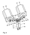
Fig. 2 ; und - Fig. 6
- perspektivisch zwei Stoffdrückerstangen der Nähmaschine nach den
Fig. 1 bis 5 mit zwei druckerzeugenden Einrichtungen.
- Fig. 1
- perspective view of a section of a sewing machine, in which removed to visualize internal details housing elements and components are removed;
- Fig. 2
- an operator side view of cutting the sewing machine behind
Fig. 1 ; - Fig. 3
- a view according to viewing direction III in
Fig. 2 ; - Fig. 4
- a view according to viewing direction IV in
Fig. 3 ; - Fig. 5
- a view according to the direction V in
Fig. 2 ; and - Fig. 6
- in perspective, two fabric presser rods of the sewing machine after the
Fig. 1 to 5 with two pressure generating devices.
Eine Nähmaschine 1 hat einen oberen Arm 2 mit einem Maschinenkopf 3, einen in der Zeichnung nicht dargestellten vertikalen Ständer und ein unteres Gehäuse, das üblicherweise als Grundplatte 4 bezeichnet wird. Die Grundplatte 4 hat eine nach oben ragende Säule 5, weshalb die Nähmaschine 1 auch als Säulen-Nähmaschine bezeichnet wird. Die Nähmaschine 1 kann als Ärmeleinnähmaschine eingesetzt werden.A
Im Arm 2 ist eine nicht näher dargestellte Armwelle zum auf- und abgehenden Antrieb einer nicht dargestellten Nadelstange mit Nadelstangenachse 6 drehbar gelagert. Der Antrieb der Armwelle erfolgt über einen im Arm 2 montierten Antriebsmotor und einen Riemenantrieb, die beide in der Zeichnung nicht dargestellt sind. Über die Armwelle und einen ebenfalls nicht dargestellten Kurbeltrieb ist die im Arm 2 vertikal gelagerte Nadelstange vertikal auf- und abgehend antreibbar, wobei die Nadelstange an ihrem unteren Ende eine Nadel trägt. Unterhalb der Nadelstange ist in der Säule 5 ein Greifer drehantreibbar gelagert. Zu vernähende Nähgutteile werden über eine die Oberseite der Säule 5 bildende Stichlochplatte geführt, durch die die Nadel in den Bereich des Greifers hindurchtritt. Die Nadel einerseits und der Greifer andererseits stellen Sticherzeugungsmittel der Nähmaschine 1 dar.In
Zum Vorschieben der miteinander zu vernähenden Nähgutteile in einer Haupt-Nährichtung 7 (vgl.
Die untere Stoffschieber-Baugruppe 8 hat zwei nebeneinander laufende untere Transportbänder 10, 11, die als Polyurethan-beschichtete Zahnriemen ausgeführt sind. Die Zahnriemen können auch aus einem Elastomer hergestellt sein. Die Transportbänder 10, 11 werden über in der Säule 5 gelagerte Zahnscheiben 12 von einem gemeinsamen Antrieb 12a so angetrieben, dass sie sich relativ zur Stichplatte in der Nährichtung 7 mit der gleichen Geschwindigkeit bewegen. Dieser Antrieb 12a der beiden unteren Transportbänder 10, 11 ist beispielsweise in der
Mit dem in der
Dort, wo das obere Transportband 13 mit dem unteren Transportband 10 zum Nähgutvorschub zwischenliegender Nähgutteile zusammenwirkt, ist das obere Transportband 13 über eine an einem Drückerfuß 14 gelagerte Umlenkrolle umgelenkt. Der Drückerfuß 14 stellt eine druckabgebende Einrichtung der Nähmaschine 1 dar, die über das obere Transportband 13 mit den zu vernähenden Nähgutteilen, also mit dem zu vernähenden Stoff, zusammenwirkt. Eine weitere Umlenkung des oberen Transportbandes 13 erfolgt über einen am Maschinenkopf 3 festgelegten Ausleger 15. Angetrieben ist das obere Transportband 13 über eine Zahnscheibe 16. Diese wird von einem Bandantriebs-Servomotor 17 angetrieben, der als Schrittmotor ausgeführt ist.There, where the
Der Drückerfuß 14 ist an einer ersten, kopfseitigen Stoffdrückerstange 18 montiert. Diese ist in einer Stoffstangenbuchse 19 axial geführt, die am Maschinenkopf 3 festgelegt ist. Der Drückerfuß 14 ist am nähgutseitigen Ende der ersten Stoffdrückerstange 18 festgelegt. Am gegenüberliegenden, maschinenkopfseitigen Ende wirkt die erste Stoffdrückerstange 18 mit einer ersten druckerzeugenden Einrichtung 20 zusammen. Diese hat einen als Schrittmotor ausgeführten Servomotor 21 und als Übertragungsmechanismus einen Übertragungshebel 22 (vgl.
Wie insbesondere der
Auch die zweite Stoffdrückerstange 30 ist in einer Stoffstangenbuchse 19 in ihrer Axialbewegung geführt.The second
Die beiden Stoffdrückerstangen 18, 30 und damit auch ihre beiden maschinenkopfseitigen Enden sind einander direkt benachbart angeordnet.The two
Über entsprechende Signalverbindungen, die in der Zeichnung nicht dargestellt sind, stehen die beiden Servomotoren 21 der beiden druckerzeugenden Einrichtungen 20, 31, der Bandantriebs-Servomotor 17 und der Antrieb für die Armwelle der Nähmaschine 1 mit einer zentralen Steuereinrichtung 33 (vgl.
Eine Hubbewegung der Mitnehmerbolzen 28 aufgrund der Betätigung der druckerzeugenden Einrichtungen 20, 31 ist über eine am Maschinenkopf 3 festgelegte Langlochplatte 35 geführt.A lifting movement of the driving pins 28 due to the actuation of the pressure-generating
Beim Betrieb der Nähmaschine 1 sorgen die synchronisiert miteinander laufenden Transportbänder 10, 11 und 13, 13 a für einen Vorschub der Nähgutteile in der Nährichtung 7. Über die beiden druckerzeugenden Einrichtungen 20 und 31 kann ein Schlupf zwischen den Transportbändern 10 und 13 einerseits und zwischen den Transportbändern 11 und 13a andererseits vorgegeben werden. Je nach dem relativen Schlupf zwischen den Transportbändern 10 und 13 einerseits und den Transportbändern 11 und 13a andererseits kann dem Vorschub in der Nährichtung 7 ein Krümmungsbeitrag hinzugefügt werden, so dass eine in der Ebene des Nähguts gekrümmte Naht mit vom Schlupfverhältnis abhängigem Krümmungsradius genäht werden kann. Über das Verhältnis der Bandlaufgeschwindigkeiten der Bänder 10 und 13 kann zudem, falls gewünscht, ein Kräuselmaß vorgegeben werden.During operation of the
Je nach der Dicke der Nähgutteile zwischen den Transportbändern 10, 13 einerseits und zwischen den Transportbändern 11, 13 a andererseits ergibt sich bei gegebenem Druck, den die druckerzeugenden Einrichtungen 20, 31 auf die Stoffdrückerstangen 18, 30 ausüben, also bei gegebenem Drehmoment der Servomotoren 21, eine zugehörige Drehposition der Motorwellen 23, die von den integrierten Positionsgebern der Servomotoren 21 erfasst werden kann. Über die Positionsgeber ist daher eine Messung der momentanen Dicke des Nähgutes möglich. Diese Dickenmessung kann von der Steuereinrichtung 33 beispielsweise zur Vorgabe einer Stichlänge oder einer Vorschub-Transportgeschwindigkeit oder einer Fadenspannung genutzt werden.Depending on the thickness of the workpieces between the
Der Druck, den die druckerzeugenden Einrichtungen 20, 31 und damit die Stoffdrückerstangen 18, 30 auf das Nähgut ausüben, kann, gesteuert durch die Steuereinrichtung 33, während der Durchführung eines Stichs gemäß einer Druck-Vorgabekurve, den die Servomotoren 21 über die Übertragungshebel 22 auf die Stoffdrückerstangen 18, 30 ausüben, variiert werden. Insbesondere kann der Fußdruck über die beiden Stoffdrückerstangen 18, 30 variabel während eines Stichs vorgegeben werden. Da die Servomotoren 21 unabhängig vom Armwellenantrieb arbeiten, kann diese Druck-Vorgabekurve synchronisiert zur Sticherzeugung abgearbeitet werden, dies ist jedoch nicht zwingend. Beispielsweise kann bei jedem zweiten Stich ein Druck gemäß einer anderen Druck-Vorgabekurve oder, soweit auch der Hub der Stoffdrückerstangen 18, 30 einbezogen wird, gemäß einem anderen Druck- und Bewegungsprofil ausgeübt werden.The pressure exerted by the pressure-generating
Eine Fadenspannung eines Nähfadens der Nähmaschine 1 kann abhängig vom Druck, der über die druckerzeugenden Einrichtungen 20, 31 ausgeübt wird, gesteuert über die Steuereinrichtung 33 vorgegeben werden. Auch eine Druckvorgabe abhängig von einem Vorgabewert, insbesondere von der Armwellendrehzahl, abhängig von der Stichlänge oder individuell während verschiedener Stichsegmente ist möglich. Mit den druckerzeugenden Einrichtungen 20, 31 kann zudem ein Hub der Stoffdrückerstangen 18, 30 während des Nähbetriebs und insbesondere während eines Stichs, individuell gemäß einer Hub-Vorgabekurve, den die Servomotoren 21 über die Übertragungshebel 22 den Stoffdrückerstangen 18, 30 vermitteln, variiert werden. Auch dieser Hub kann, z. B. zur Vorgabe einer über die Transportbänder 10, 11 und 13 zu erzeugenden Stoff-Mehrweite insbesondere abhängig von einem Vorgabewert variabel vorgegeben werden. Abhängig von diesem Hub kann beispielsweise auch die Fadenspannung vorgegeben werden. Auch eine Hubvorgabe abhängig von der Armwellendrehzahl ist möglich.A yarn tension of a sewing thread of the
Aufgrund der individuellen Ansteuerbarkeit der beiden Servomotoren 21 ist eine Alternierung des Betriebs der beiden Stoffdrückerstangen 18, 30 möglich.Due to the individual controllability of the two
Da über die Mitnehmerbolzen 28 die Servomotoren 21 auch eine Zugwirkung auf die Stoffdrückerstangen 18, 30 ausüben können, ist hierüber auch eine Lüftung der beiden Drückerfüße 14, 29 möglich.Since the
Die Steuereinrichtung 33 kann vorab programmierte Abläufe mit Druck- und Hub-Vorgabekurven abarbeiten.The
Über eine entsprechende Vorgabe durch die Steuereinrichtung 33 ist eine Schnellverstellung der Hubhöhe, die die Stoffdrückerstangen 18, 30 während des Nähbetriebs vollführen, möglich.By means of a corresponding specification by the
Claims (15)
Applications Claiming Priority (1)
| Application Number | Priority Date | Filing Date | Title |
|---|---|---|---|
| DE102008030797A DE102008030797A1 (en) | 2008-06-28 | 2008-06-28 | Sewing machine and method for operating such a sewing machine |
Publications (2)
| Publication Number | Publication Date |
|---|---|
| EP2138620A1 true EP2138620A1 (en) | 2009-12-30 |
| EP2138620B1 EP2138620B1 (en) | 2012-05-16 |
Family
ID=41105232
Family Applications (1)
| Application Number | Title | Priority Date | Filing Date |
|---|---|---|---|
| EP20090007123 Active EP2138620B1 (en) | 2008-06-28 | 2009-05-28 | Sewing machine and method for operating same |
Country Status (5)
| Country | Link |
|---|---|
| EP (1) | EP2138620B1 (en) |
| JP (1) | JP5286172B2 (en) |
| KR (1) | KR101532097B1 (en) |
| CN (1) | CN101613912B (en) |
| DE (1) | DE102008030797A1 (en) |
Cited By (1)
| Publication number | Priority date | Publication date | Assignee | Title |
|---|---|---|---|---|
| CN105316876A (en) * | 2014-09-02 | 2016-02-10 | 保定泽泰服装机械制造有限公司 | A synchronous belt cloth feeding mechanism of a sewing machine |
Families Citing this family (10)
| Publication number | Priority date | Publication date | Assignee | Title |
|---|---|---|---|---|
| CN102953244B (en) * | 2012-11-06 | 2015-06-17 | 贺欣机械厂股份有限公司 | Method and device for controlling synchronous operating of sewing equipment stitching and feeding motors |
| CN103668798A (en) * | 2013-12-19 | 2014-03-26 | 吴江市菀坪宝得利缝制设备机械厂 | Vertical feeding mechanism of sewing machine |
| DE102014213457A1 (en) | 2014-07-10 | 2016-01-14 | Dürkopp Adler AG | Method for processing a sewing program for sewing sewing material and the sewing machine therefor |
| CN105063899B (en) * | 2015-08-04 | 2018-01-30 | 江苏天淼软件开发有限公司 | A kind of cloth-rolling device on braid automatic sewing machine |
| CN107488942B (en) * | 2016-06-10 | 2022-01-07 | Juki株式会社 | Flat-seam sewing machine |
| CN105887348B (en) * | 2016-06-23 | 2018-07-31 | 钟治超 | A kind of sewing machine feeding mechanism |
| DE102016011557A1 (en) * | 2016-09-26 | 2018-03-29 | Pfaff Industriesysteme Und Maschinen Gmbh | Sewing machine with a puller device |
| CN107099940B (en) * | 2017-05-25 | 2020-03-06 | 杰克缝纫机股份有限公司 | Sewing machine |
| CN107099941B (en) * | 2017-05-25 | 2020-04-17 | 杰克缝纫机股份有限公司 | Sewing machine |
| CN111379083A (en) * | 2018-12-30 | 2020-07-07 | 浙江中捷缝纫科技有限公司 | Presser foot lifting device, sewing machine and control method of presser foot lifting device |
Citations (5)
| Publication number | Priority date | Publication date | Assignee | Title |
|---|---|---|---|---|
| DE8213129U1 (en) * | 1982-05-06 | 1984-08-16 | Kochs Adler Ag, 4800 Bielefeld | SEWING MACHINE WITH A FEED DEVICE FOR THE WORKPIECE TO BE SEWN |
| DE102004019001A1 (en) * | 2003-04-21 | 2004-12-16 | Juki Corp., Tokio/Tokyo | Differential-feed sewing machine controls motors of upper and lower feeders based on preset input which determines feed amount of upper feeders and lower feeder for every sewing areas which are switched during sewing |
| EP1897985A2 (en) | 2006-09-08 | 2008-03-12 | Dürkopp Adler Aktiengesellschaft | Sewing machine for sewing two pieces of material while incorporating fullness |
| EP1897984A2 (en) | 2006-09-08 | 2008-03-12 | Dürkopp Adler Aktiengesellschaft | Sewing machine |
| EP2000571A2 (en) * | 2007-06-08 | 2008-12-10 | Dürkopp Adler Aktiengesellschaft | Sewing machine and method for operating such a sewing machine |
Family Cites Families (9)
| Publication number | Priority date | Publication date | Assignee | Title |
|---|---|---|---|---|
| JPS5540136Y2 (en) * | 1974-07-10 | 1980-09-19 | ||
| JPH05192464A (en) * | 1992-01-20 | 1993-08-03 | Tokai Ind Sewing Mach Co Ltd | Fabric holder driving device of sewing machine |
| JP2001198373A (en) * | 2000-01-20 | 2001-07-24 | Hirose Mfg Co Ltd | Feed mechanism in sewing machine |
| DE10216810A1 (en) * | 2002-04-16 | 2003-11-06 | Duerkopp Adler Ag | Buttonhole sewing machine |
| DE10233017B4 (en) * | 2002-07-20 | 2004-09-30 | Dürkopp Adler AG | Eye buttonhole sewing machine |
| JP3903011B2 (en) * | 2003-01-23 | 2007-04-11 | 株式会社廣瀬製作所 | Leading roller |
| JP2005192620A (en) * | 2003-12-26 | 2005-07-21 | Juki Corp | Cloth feeding mechanism of sewing machine |
| DE102005049771A1 (en) * | 2005-10-18 | 2007-04-19 | Dürkopp Adler AG | Sewing machine comprises a presser foot position sensor, a material thickness sensor and a control unit for controlling the sewing machine in response to signals from the sensors |
| JP2009089833A (en) * | 2007-10-05 | 2009-04-30 | Juki Corp | Cloth feeder of sewing machine |
-
2008
- 2008-06-28 DE DE102008030797A patent/DE102008030797A1/en not_active Withdrawn
-
2009
- 2009-05-28 EP EP20090007123 patent/EP2138620B1/en active Active
- 2009-06-24 JP JP2009149852A patent/JP5286172B2/en active Active
- 2009-06-24 KR KR1020090056429A patent/KR101532097B1/en active IP Right Grant
- 2009-06-26 CN CN200910149196XA patent/CN101613912B/en active Active
Patent Citations (5)
| Publication number | Priority date | Publication date | Assignee | Title |
|---|---|---|---|---|
| DE8213129U1 (en) * | 1982-05-06 | 1984-08-16 | Kochs Adler Ag, 4800 Bielefeld | SEWING MACHINE WITH A FEED DEVICE FOR THE WORKPIECE TO BE SEWN |
| DE102004019001A1 (en) * | 2003-04-21 | 2004-12-16 | Juki Corp., Tokio/Tokyo | Differential-feed sewing machine controls motors of upper and lower feeders based on preset input which determines feed amount of upper feeders and lower feeder for every sewing areas which are switched during sewing |
| EP1897985A2 (en) | 2006-09-08 | 2008-03-12 | Dürkopp Adler Aktiengesellschaft | Sewing machine for sewing two pieces of material while incorporating fullness |
| EP1897984A2 (en) | 2006-09-08 | 2008-03-12 | Dürkopp Adler Aktiengesellschaft | Sewing machine |
| EP2000571A2 (en) * | 2007-06-08 | 2008-12-10 | Dürkopp Adler Aktiengesellschaft | Sewing machine and method for operating such a sewing machine |
Cited By (1)
| Publication number | Priority date | Publication date | Assignee | Title |
|---|---|---|---|---|
| CN105316876A (en) * | 2014-09-02 | 2016-02-10 | 保定泽泰服装机械制造有限公司 | A synchronous belt cloth feeding mechanism of a sewing machine |
Also Published As
| Publication number | Publication date |
|---|---|
| CN101613912A (en) | 2009-12-30 |
| JP5286172B2 (en) | 2013-09-11 |
| KR20100002168A (en) | 2010-01-06 |
| DE102008030797A1 (en) | 2009-12-31 |
| CN101613912B (en) | 2012-11-21 |
| EP2138620B1 (en) | 2012-05-16 |
| JP2010005403A (en) | 2010-01-14 |
| KR101532097B1 (en) | 2015-06-26 |
Similar Documents
| Publication | Publication Date | Title |
|---|---|---|
| EP2138620B1 (en) | Sewing machine and method for operating same | |
| DE3832124C2 (en) | ||
| DE102017107281A1 (en) | sewing machine | |
| EP2000571B1 (en) | Sewing machine and method for operating such a sewing machine | |
| EP2206816B1 (en) | Two needles sewing machine | |
| DE19516825A1 (en) | Wire feeder | |
| DE4313760C2 (en) | Automatic multi-needle sewing machine | |
| EP1048772A1 (en) | Apparatus and method for automatic sewing | |
| DE19610411A1 (en) | Appts. for automatic prodn. of garment sleeves | |
| DE102006042334A1 (en) | sewing machine | |
| DE2902774C2 (en) | Sewing machine for producing bulge seams on moccasin shoes | |
| DE10136543C1 (en) | Buttonhole sewing machine has a clamp/cutter unit for the upper thread, mounted at a body containing cutter swing and closing drives, in a simple and low-cost structure | |
| DE3743281A1 (en) | SEWING MACHINE TO SEE A TAPE | |
| DE3000831C2 (en) | Automatic sewing machine for producing a seam with a fastening seam and locking stitches | |
| DE102009004218A1 (en) | Thread cutting device for a sewing machine | |
| DE102007055178A1 (en) | Embroidery sewing machine used for sewing tape and cord on cloth has sending member that sends out and guides cord-like raw material supported by a support member to direction of needle former position | |
| EP1897985B1 (en) | Sewing machine for sewing two pieces of material while incorporating fullness | |
| EP2206817A1 (en) | Switchable needle bar drive device | |
| DE19530867A1 (en) | Linking mechanism | |
| WO2023242171A1 (en) | Sewing unit | |
| DE8316282U1 (en) | Feed drive for a stitch group sewing machine | |
| DE3411177C2 (en) | Sewing machine with a sewing head with rotating housing | |
| DE102016011557A1 (en) | Sewing machine with a puller device | |
| DE2230054C3 (en) | Sewing machine for sewing on pockets with folded piping | |
| EP3399089B1 (en) | Method and sewing machine for generating a bobbin thread end of a seam with a predetermined protrusion |
Legal Events
| Date | Code | Title | Description |
|---|---|---|---|
| PUAI | Public reference made under article 153(3) epc to a published international application that has entered the european phase |
Free format text: ORIGINAL CODE: 0009012 |
|
| AK | Designated contracting states |
Kind code of ref document: A1 Designated state(s): AT BE BG CH CY CZ DE DK EE ES FI FR GB GR HR HU IE IS IT LI LT LU LV MC MK MT NL NO PL PT RO SE SI SK TR |
|
| 17P | Request for examination filed |
Effective date: 20100312 |
|
| 17Q | First examination report despatched |
Effective date: 20100414 |
|
| GRAP | Despatch of communication of intention to grant a patent |
Free format text: ORIGINAL CODE: EPIDOSNIGR1 |
|
| GRAS | Grant fee paid |
Free format text: ORIGINAL CODE: EPIDOSNIGR3 |
|
| GRAA | (expected) grant |
Free format text: ORIGINAL CODE: 0009210 |
|
| AK | Designated contracting states |
Kind code of ref document: B1 Designated state(s): AT BE BG CH CY CZ DE DK EE ES FI FR GB GR HR HU IE IS IT LI LT LU LV MC MK MT NL NO PL PT RO SE SI SK TR |
|
| REG | Reference to a national code |
Ref country code: GB Ref legal event code: FG4D Free format text: NOT ENGLISH |
|
| REG | Reference to a national code |
Ref country code: CH Ref legal event code: EP |
|
| REG | Reference to a national code |
Ref country code: AT Ref legal event code: REF Ref document number: 558149 Country of ref document: AT Kind code of ref document: T Effective date: 20120615 |
|
| REG | Reference to a national code |
Ref country code: RO Ref legal event code: EPE |
|
| REG | Reference to a national code |
Ref country code: IE Ref legal event code: FG4D Free format text: LANGUAGE OF EP DOCUMENT: GERMAN |
|
| REG | Reference to a national code |
Ref country code: DE Ref legal event code: R096 Ref document number: 502009003512 Country of ref document: DE Effective date: 20120719 |
|
| REG | Reference to a national code |
Ref country code: NL Ref legal event code: VDEP Effective date: 20120516 |
|
| REG | Reference to a national code |
Ref country code: LT Ref legal event code: MG4D Effective date: 20120516 |
|
| PG25 | Lapsed in a contracting state [announced via postgrant information from national office to epo] |
Ref country code: LT Free format text: LAPSE BECAUSE OF FAILURE TO SUBMIT A TRANSLATION OF THE DESCRIPTION OR TO PAY THE FEE WITHIN THE PRESCRIBED TIME-LIMIT Effective date: 20120516 Ref country code: SE Free format text: LAPSE BECAUSE OF FAILURE TO SUBMIT A TRANSLATION OF THE DESCRIPTION OR TO PAY THE FEE WITHIN THE PRESCRIBED TIME-LIMIT Effective date: 20120516 Ref country code: PL Free format text: LAPSE BECAUSE OF FAILURE TO SUBMIT A TRANSLATION OF THE DESCRIPTION OR TO PAY THE FEE WITHIN THE PRESCRIBED TIME-LIMIT Effective date: 20120516 Ref country code: IS Free format text: LAPSE BECAUSE OF FAILURE TO SUBMIT A TRANSLATION OF THE DESCRIPTION OR TO PAY THE FEE WITHIN THE PRESCRIBED TIME-LIMIT Effective date: 20120916 Ref country code: CY Free format text: LAPSE BECAUSE OF FAILURE TO SUBMIT A TRANSLATION OF THE DESCRIPTION OR TO PAY THE FEE WITHIN THE PRESCRIBED TIME-LIMIT Effective date: 20120516 Ref country code: NO Free format text: LAPSE BECAUSE OF FAILURE TO SUBMIT A TRANSLATION OF THE DESCRIPTION OR TO PAY THE FEE WITHIN THE PRESCRIBED TIME-LIMIT Effective date: 20120816 Ref country code: FI Free format text: LAPSE BECAUSE OF FAILURE TO SUBMIT A TRANSLATION OF THE DESCRIPTION OR TO PAY THE FEE WITHIN THE PRESCRIBED TIME-LIMIT Effective date: 20120516 |
|
| BERE | Be: lapsed |
Owner name: DURKOPP ADLER A.G. Effective date: 20120531 |
|
| PG25 | Lapsed in a contracting state [announced via postgrant information from national office to epo] |
Ref country code: SI Free format text: LAPSE BECAUSE OF FAILURE TO SUBMIT A TRANSLATION OF THE DESCRIPTION OR TO PAY THE FEE WITHIN THE PRESCRIBED TIME-LIMIT Effective date: 20120516 Ref country code: PT Free format text: LAPSE BECAUSE OF FAILURE TO SUBMIT A TRANSLATION OF THE DESCRIPTION OR TO PAY THE FEE WITHIN THE PRESCRIBED TIME-LIMIT Effective date: 20120917 Ref country code: HR Free format text: LAPSE BECAUSE OF FAILURE TO SUBMIT A TRANSLATION OF THE DESCRIPTION OR TO PAY THE FEE WITHIN THE PRESCRIBED TIME-LIMIT Effective date: 20120516 Ref country code: LV Free format text: LAPSE BECAUSE OF FAILURE TO SUBMIT A TRANSLATION OF THE DESCRIPTION OR TO PAY THE FEE WITHIN THE PRESCRIBED TIME-LIMIT Effective date: 20120516 Ref country code: GR Free format text: LAPSE BECAUSE OF FAILURE TO SUBMIT A TRANSLATION OF THE DESCRIPTION OR TO PAY THE FEE WITHIN THE PRESCRIBED TIME-LIMIT Effective date: 20120817 |
|
| PG25 | Lapsed in a contracting state [announced via postgrant information from national office to epo] |
Ref country code: MC Free format text: LAPSE BECAUSE OF NON-PAYMENT OF DUE FEES Effective date: 20120531 |
|
| PG25 | Lapsed in a contracting state [announced via postgrant information from national office to epo] |
Ref country code: DK Free format text: LAPSE BECAUSE OF FAILURE TO SUBMIT A TRANSLATION OF THE DESCRIPTION OR TO PAY THE FEE WITHIN THE PRESCRIBED TIME-LIMIT Effective date: 20120516 Ref country code: SK Free format text: LAPSE BECAUSE OF FAILURE TO SUBMIT A TRANSLATION OF THE DESCRIPTION OR TO PAY THE FEE WITHIN THE PRESCRIBED TIME-LIMIT Effective date: 20120516 Ref country code: EE Free format text: LAPSE BECAUSE OF FAILURE TO SUBMIT A TRANSLATION OF THE DESCRIPTION OR TO PAY THE FEE WITHIN THE PRESCRIBED TIME-LIMIT Effective date: 20120516 Ref country code: NL Free format text: LAPSE BECAUSE OF FAILURE TO SUBMIT A TRANSLATION OF THE DESCRIPTION OR TO PAY THE FEE WITHIN THE PRESCRIBED TIME-LIMIT Effective date: 20120516 |
|
| REG | Reference to a national code |
Ref country code: IE Ref legal event code: MM4A |
|
| PG25 | Lapsed in a contracting state [announced via postgrant information from national office to epo] |
Ref country code: MK Free format text: LAPSE BECAUSE OF FAILURE TO SUBMIT A TRANSLATION OF THE DESCRIPTION OR TO PAY THE FEE WITHIN THE PRESCRIBED TIME-LIMIT Effective date: 20120516 Ref country code: IT Free format text: LAPSE BECAUSE OF FAILURE TO SUBMIT A TRANSLATION OF THE DESCRIPTION OR TO PAY THE FEE WITHIN THE PRESCRIBED TIME-LIMIT Effective date: 20120516 Ref country code: BE Free format text: LAPSE BECAUSE OF NON-PAYMENT OF DUE FEES Effective date: 20120531 |
|
| PLBE | No opposition filed within time limit |
Free format text: ORIGINAL CODE: 0009261 |
|
| STAA | Information on the status of an ep patent application or granted ep patent |
Free format text: STATUS: NO OPPOSITION FILED WITHIN TIME LIMIT |
|
| REG | Reference to a national code |
Ref country code: FR Ref legal event code: ST Effective date: 20130307 |
|
| 26N | No opposition filed |
Effective date: 20130219 |
|
| PG25 | Lapsed in a contracting state [announced via postgrant information from national office to epo] |
Ref country code: IE Free format text: LAPSE BECAUSE OF NON-PAYMENT OF DUE FEES Effective date: 20120528 Ref country code: FR Free format text: LAPSE BECAUSE OF NON-PAYMENT OF DUE FEES Effective date: 20120716 |
|
| REG | Reference to a national code |
Ref country code: DE Ref legal event code: R097 Ref document number: 502009003512 Country of ref document: DE Effective date: 20130219 |
|
| PG25 | Lapsed in a contracting state [announced via postgrant information from national office to epo] |
Ref country code: BG Free format text: LAPSE BECAUSE OF FAILURE TO SUBMIT A TRANSLATION OF THE DESCRIPTION OR TO PAY THE FEE WITHIN THE PRESCRIBED TIME-LIMIT Effective date: 20120816 Ref country code: MT Free format text: LAPSE BECAUSE OF FAILURE TO SUBMIT A TRANSLATION OF THE DESCRIPTION OR TO PAY THE FEE WITHIN THE PRESCRIBED TIME-LIMIT Effective date: 20120516 |
|
| PG25 | Lapsed in a contracting state [announced via postgrant information from national office to epo] |
Ref country code: ES Free format text: LAPSE BECAUSE OF FAILURE TO SUBMIT A TRANSLATION OF THE DESCRIPTION OR TO PAY THE FEE WITHIN THE PRESCRIBED TIME-LIMIT Effective date: 20120827 |
|
| REG | Reference to a national code |
Ref country code: CH Ref legal event code: PL |
|
| GBPC | Gb: european patent ceased through non-payment of renewal fee |
Effective date: 20130528 |
|
| PG25 | Lapsed in a contracting state [announced via postgrant information from national office to epo] |
Ref country code: CH Free format text: LAPSE BECAUSE OF NON-PAYMENT OF DUE FEES Effective date: 20130531 Ref country code: LI Free format text: LAPSE BECAUSE OF NON-PAYMENT OF DUE FEES Effective date: 20130531 |
|
| PG25 | Lapsed in a contracting state [announced via postgrant information from national office to epo] |
Ref country code: GB Free format text: LAPSE BECAUSE OF NON-PAYMENT OF DUE FEES Effective date: 20130528 Ref country code: TR Free format text: LAPSE BECAUSE OF FAILURE TO SUBMIT A TRANSLATION OF THE DESCRIPTION OR TO PAY THE FEE WITHIN THE PRESCRIBED TIME-LIMIT Effective date: 20120516 |
|
| PG25 | Lapsed in a contracting state [announced via postgrant information from national office to epo] |
Ref country code: LU Free format text: LAPSE BECAUSE OF NON-PAYMENT OF DUE FEES Effective date: 20120528 |
|
| PG25 | Lapsed in a contracting state [announced via postgrant information from national office to epo] |
Ref country code: HU Free format text: LAPSE BECAUSE OF FAILURE TO SUBMIT A TRANSLATION OF THE DESCRIPTION OR TO PAY THE FEE WITHIN THE PRESCRIBED TIME-LIMIT Effective date: 20090528 |
|
| REG | Reference to a national code |
Ref country code: AT Ref legal event code: MM01 Ref document number: 558149 Country of ref document: AT Kind code of ref document: T Effective date: 20140528 |
|
| PG25 | Lapsed in a contracting state [announced via postgrant information from national office to epo] |
Ref country code: AT Free format text: LAPSE BECAUSE OF NON-PAYMENT OF DUE FEES Effective date: 20140528 |
|
| PGFP | Annual fee paid to national office [announced via postgrant information from national office to epo] |
Ref country code: RO Payment date: 20230518 Year of fee payment: 15 Ref country code: CZ Payment date: 20230512 Year of fee payment: 15 |
|
| PGFP | Annual fee paid to national office [announced via postgrant information from national office to epo] |
Ref country code: DE Payment date: 20230725 Year of fee payment: 15 |