EP2138427A1 - Load bearer for loading and unloading loads into or out of storage areas of a shelf assembly - Google Patents
Load bearer for loading and unloading loads into or out of storage areas of a shelf assembly Download PDFInfo
- Publication number
- EP2138427A1 EP2138427A1 EP09006438A EP09006438A EP2138427A1 EP 2138427 A1 EP2138427 A1 EP 2138427A1 EP 09006438 A EP09006438 A EP 09006438A EP 09006438 A EP09006438 A EP 09006438A EP 2138427 A1 EP2138427 A1 EP 2138427A1
- Authority
- EP
- European Patent Office
- Prior art keywords
- load
- receiving means
- support
- means according
- support elements
- Prior art date
- Legal status (The legal status is an assumption and is not a legal conclusion. Google has not performed a legal analysis and makes no representation as to the accuracy of the status listed.)
- Granted
Links
Images


Classifications
-
- B—PERFORMING OPERATIONS; TRANSPORTING
- B65—CONVEYING; PACKING; STORING; HANDLING THIN OR FILAMENTARY MATERIAL
- B65G—TRANSPORT OR STORAGE DEVICES, e.g. CONVEYORS FOR LOADING OR TIPPING, SHOP CONVEYOR SYSTEMS OR PNEUMATIC TUBE CONVEYORS
- B65G1/00—Storing articles, individually or in orderly arrangement, in warehouses or magazines
- B65G1/02—Storage devices
- B65G1/04—Storage devices mechanical
- B65G1/0407—Storage devices mechanical using stacker cranes
Landscapes
- Engineering & Computer Science (AREA)
- Mechanical Engineering (AREA)
- Warehouses Or Storage Devices (AREA)
Abstract
Description
Die Erfindung betrifft ein Lastaufnahmemittel der im Oberbegriff des Anspruchs 1 genannten Art zur Ein-und Auslagerung von Lasten an bzw. von Lagerplätzen einer Regalanordnung.The invention relates to a load handling device referred to in the preamble of claim 1 for the storage and retrieval of loads to or from storage bins of a shelf assembly.
Ein Lastaufnahmemittel der betreffenden Art ist durch
Aufgrund der Aufhängung des Grundkörpers an Tragseilen führt das Lastaufnahmemittel während einer Bewegung der Aufhängung Pendelschwingungen relativ zu der Aufhängung aus. Das bekannte Lastaufnahmemittel weist ferner an gegenüberliegenden Längsrändern des Grundkörpers angeordnete Stützelemente zur Abstützung des Grundkörpers an der Regalanordnung während eines Ein- bzw. Auslagerungsvorganges auf. Bei dem bekannten Lastaufnahmemittel sind die Stützelemente in Bezug zu dem jeweiligen Längsrand des Grundkörpers aus- bzw. einfahrbar ausgebildet, wobei als Antrieb für die einzelnen Stützelemente jeweils eine Zahnstangen-Ritzel-Anordnung vorgesehen ist. Durch die Abstützung des Grundkörpers an der Regaleinheit werden während eines Ein-und Auslagerungsvorganges auftretende Kräfte wenigstens teilweise von der Regalanordnung aufgenommen. Bei dem aus der Druckschrift bekannten Lastaufnahmemittel sind die Stützelemente als Arretierungselemente ausgebildet, die in ihrer Arretierungsposition, in der die Stützelemente ausgefahren sind, formschlüssig in entsprechende Aufnahmen an der Regalanordnung eingreifen. Auf diese Weise sind Bewegungen des Lastaufnahmemittels relativ zu der Regalanordnung während eines Ein- bzw. Auslagerungsvorganges vermieden.Due to the suspension of the body to support cables, the load-carrying means performs during a movement of the suspension pendulum oscillations relative to the suspension. The known load-receiving means further comprises support elements arranged on opposite longitudinal edges of the base body for supporting the base body on the shelf assembly during a loading or unloading operation. In the known load-carrying means, the support elements are designed to be extendable or retractable relative to the respective longitudinal edge of the base body, wherein a rack-and-pinion arrangement is provided as a drive for the individual support elements. By supporting the base body on the shelf unit, forces occurring during a loading and unloading process are at least partially absorbed by the shelf assembly. In the load receiving means known from the document, the support elements are designed as locking elements, which engage in their locking position in which the support elements are extended, positively engage in corresponding receptacles on the shelf assembly. In this way, movements of the load-receiving means relative to the shelf assembly during a loading or unloading operation are avoided.
Ein ähnliches Lastaufnahmemittel ist auch aus der
Der Erfindung liegt die Aufgabe zugrunde, ein Lastaufnahmemittel der im Oberbegriff des Anspruchs 1 genannten Art anzugeben, dessen Flexibilität hinsichtlich der Ein- bzw. Auslagerung von Lasten an bzw. von Lagerplätzen einer Regalanordnung erhöht ist.The invention has for its object to provide a load handling device referred to in the preamble of claim 1 species, whose flexibility is increased in terms of storage or removal of loads to or from storage bins of a shelf assembly.
Diese Aufgabe wird durch die im Anspruch 1 angegebene Erfindung gelöst.This object is achieved by the invention defined in claim 1.
Die Erfindung geht von einem Lastaufnahmemittel aus, das sich während eines Ein- bzw. Auslagerungsvorganges mittels Stützelementen an der Regalanordnung abstützt. Der Grundgedanke der Erfindung besteht darin, das Lastaufnahmemittel so zu gestalten, daß die Lage eines Abstützpunktes, in dem sich der Grundkörper mittels des jeweiligen Stützelementes an der Regalanordnung abstützt, entlang des jeweiligen Längsrandes des Lastaufnahmemittels variabel ist. Hierzu sieht die Erfindung vor, daß wenigstens eines der Stützelemente entlang des jeweiligen Längsrandes verstellbar ist und daß dem Stützelement ein Verstellantrieb zugeordnet ist. Mittels des Verstellantriebes ist das jeweilige Stützelement entlang des zugeordneten Längsrandes verstellbar, so daß der Abstützpunkt entsprechend dem jeweiligen Belegungszustand eines Lagerplatzes frei wählbar ist.The invention is based on a load-receiving means, which is supported during a loading or unloading operation by means of supporting elements on the shelf assembly. The basic idea of the invention is to make the load-receiving means such that the position of a support point in which the base body is supported on the shelf arrangement by means of the respective support element is variable along the respective longitudinal edge of the load-receiving means. For this purpose, the invention provides that at least one of the support elements along the respective longitudinal edge is adjustable and that the adjusting element is associated with an adjustment. By means of the adjusting drive, the respective support element along the associated longitudinal edge is adjustable, so that the support point according to the respective occupancy state of a storage space is freely selectable.
Soll beispielsweise mittels des Lastaufnahmemittels eine an einem Lagerplatz eingelagerte Euro-Palette ausgelagert werden, so wird das Lastaufnahmemittel so verfahren, daß es sich vor dem entsprechenden Regal befindet. Die Lage der Stützelemente relativ zu dem zugeordneten Längsrand wird hierbei so gewählt, daß die Stützelemente, die beispielsweise und insbesondere in Bezug auf den jeweiligen Längsrand ein- bzw. ausfahrbar sind, so positioniert sind, daß die Stützelemente weder mit der auszulagernden Euro-Palette noch mit einer daneben eingelagerten Euro-Palette kollidieren. Stützt sich beispielsweise ein Stützelement unmittelbar neben der auszulagernden Euro-Palette an der Regalanordnung ab, so wird der Abstand der Stützelemente entlang des betreffenden Längsrandes vorzugsweise größer als die Breite der Euro-Palette eingestellt.If, for example, by means of the load-handling device a euro pallet stored at a storage location is to be outsourced, then the load-receiving means is moved in such a way that it is located in front of the corresponding shelf. The position of the support elements relative to the associated longitudinal edge is in this case selected so that the support elements, which are, for example and in particular with respect to the respective longitudinal edge on or extendable, are positioned so that the support elements neither collide with the outsourced euro pallet still with an adjacent stored euro pallet. If, for example, a supporting element is supported on the shelf arrangement directly next to the euro pallet to be outsourced, then the spacing of the supporting elements along the respective longitudinal edge is preferably set greater than the width of the euro pallet.
Soll demgegenüber mittels des Lastaufnahmemittels eine Industriepalette ein- bzw. ausgelagert werden, so wird aufgrund der größeren Breite der Industriepalette ein größerer Abstand zwischen den Stützelementen eines Längsrandes erforderlich. Durch entsprechende Verstellung der dem betreffenden Längsrand zugeordneten Stützelemente relativ zueinander wird der erforderliche größere Abstand erreicht.If, on the other hand, an industrial pallet is to be stored or retrieved by means of the load handling device, a larger distance between the supporting elements of a longitudinal edge is required due to the greater width of the industrial pallet. By appropriate adjustment of the respective longitudinal edge associated support elements relative to each other, the required greater distance is achieved.
Auf diese Weise ist hinsichtlich der Ein- und Auslagerung von Lasten eine große Flexibilität erzielt, indem die Lage der Abstützpunkte des Grundkörpers an der Regalanordnung durch entsprechende Verstellung der Stützelemente relativ zueinander und zu dem Grundkörper frei wählbar ist. Auf diese Weise ist es insbesondere möglich, mittels des erfindungsgemäßen Lastaufnahmemittels Ein- bzw. Auslagerungsvorgänge sowohl in sogenannten Dreifeld-Lageranordnungen als auch in sogenannten Zweifeld-Lageranordnungen auszuführen.In this way, a great deal of flexibility in terms of the storage and retrieval of loads achieved by the position of the support points of the body to the shelf assembly by appropriate adjustment of the support elements relative to each other and to the body is freely selectable. In this way, it is in particular possible by means of the load handling device according to the invention to carry out loading or unloading operations both in so-called three-field bearing arrangements and in so-called double-field storage arrangements.
Ein weiterer Vorteil der Erfindung besteht darin, daß aufgrund der Verstellbarkeit wenigstens eines der Stützelemente an dem zugeordneten Längsrand die Stützelemente relativ zueinander und zu dem Grundkörper so positioniert werden können, daß Kollisionen der Stütz-elemente mit in der Regalanordnung eingelagerten Lasten zuverlässig vermieden sind.Another advantage of the invention is that due to the adjustability of at least one of the support members on the associated longitudinal edge, the support members relative to each other and to the body can be positioned so that collisions of the support elements are reliably prevented with stored in the shelf assembly loads.
Erfindungsgemäß können anstelle von Tragseilen zur Verbindung zwischen einer Aufhängung und dem Lastaufnahmemittel auch andere flexible Verbindungsmittel, beispielsweise ketten- oder bandförmige Verbindungsmittel verwendet werden.According to the invention, instead of supporting cables for connection between a suspension and the load receiving means Other flexible connecting means, such as chain or band-shaped connecting means may be used.
Erfindungsgemäß ist es grundsätzlich ausreichend, wenn sich bei einer Verstellung eines Stützelementes entlang des jeweiligen Längsrandes die Position des dem Grundkörper abgewandten Endes des Stützelementes relativ zu dem Längsrand verändert. Dies kann beispiels-weise dadurch erreicht werden, daß die Stützelemente schwenkbar an dem Grundkörper angeordnet sind, so daß das Stützelement entsprechend der jeweiligen Schwenklage bei gleicher Position des Lastaufnahmemittels relativ zu der Regalanordnung an unterschiedlichen Stellen der Regalanordnung zur Auflage gelangt. Eine außerordentlich vorteilhafte Weiterbildung der Erfindung sieht vor, daß das Stützelement entlang einer linearen Verstellachse verstellbar ist. Bei dieser Ausführungsform sind die Freiheiten bei der Wahl der Position des Stützelementes an dem zugeordneten Längsrand besonders groß und lediglich durch den Verstellhub des Verstellantriebes begrenzt. Ein weiterer Vorteil dieser Ausführungsform besteht darin, daß Verstellantriebe zur Verstellung des Stützelementes entlang einer linearen Verstellachse relativ einfach im Aufbau und damit relativ kostengünstig sind.According to the invention, it is basically sufficient if, during an adjustment of a support element along the respective longitudinal edge, the position of the end remote from the base body of the support element changes relative to the longitudinal edge. This can be achieved, for example, in that the support elements are pivotally mounted on the base body, so that the support element corresponding to the respective pivot position at the same position of the load receiving means relative to the shelf assembly at different points of the shelf assembly comes to rest. An extremely advantageous development of the invention provides that the support element along a linear adjustment axis is adjustable. In this embodiment, the freedoms in the choice of the position of the support element at the associated longitudinal edge are particularly large and limited only by the Verstellhub the adjustment. Another advantage of this embodiment is that adjusting drives for adjusting the support element along a linear adjustment axis are relatively simple in construction and thus relatively inexpensive.
Eine vorteilhafte Weiterbildung der vorgenannten Ausführungsform sieht vor, daß die lineare Verstellachse zur Längsmittelebene des Grundkörpers im wesentlichen parallel verläuft.An advantageous development of the aforementioned embodiment provides that the linear adjustment axis to the longitudinal center plane of the base body is substantially parallel.
Entsprechend den jeweiligen Anforderungen kann ein beliebiger geeigneter Verstellantrieb vorgesehen sein, beispielsweise ein pneumatisch oder hydraulisch arbeitender Verstellantrieb. Eine vorteilhafte Weiterbildung der Erfindung sieht insoweit vor, daß der Verstellantrieb ein elektromotorischer Verstellantrieb ist. Entsprechende Elektromotoren stehen als relativ einfache und kostengünstige Standardbauteile zur Verfügung. Ein weiterer Vorteil dieser Ausführungsform besteht darin, daß der Verstellantrieb ausschließlich mit elektrischer Energie versorgt werden muß. Im Vergleich zu pneumatischen oder hydraulischen Antrieben ergibt sich dadurch ein wesentlich einfacherer Aufbau des Lastaufnahmemittels.According to the respective requirements, any suitable adjusting drive can be provided, for example a pneumatically or hydraulically operating adjusting drive. An advantageous development of the invention provides so far that the adjustment an electric motor adjustment is. Corresponding electric motors are available as relatively simple and inexpensive standard components. Another advantage of this embodiment is that the adjustment must be supplied exclusively with electrical energy. Compared to pneumatic or hydraulic drives, this results in a much simpler structure of the lifting device.
Erfindungsgemäß ist es grundsätzlich ausreichend, wenn an wenigstens einem der Längsränder wenigstens ein entlang des Längsrandes verstellbares Stützelement vorgesehen ist. Bei einer solchen Ausführungsform können also an einem Längsrand beispielsweise ein ortsfestes und ein verstellbares Stützelement angeordnet sein. Bei einer solchen Ausführungsform wird somit ein erforderlicher Abstand zwischen den Stützelementen dadurch eingestellt, daß das verstellbare Stützelement relativ zu dem ortsfesten Stützelement entsprechend verstellt wird. Um die Flexibilität des Lastaufnahmemittels hinsichtlich der Wahl des Abstützpunktes weiter zu erhöhen, sieht eine vorteilhafte Weiterbildung der Erfindung vor, daß an wenigstens einem der Längsränder des Grundkörpers wenigstens zwei entlang des Längsrandes verstellbare Stützelemente vorgesehen sind. Sind einem Längsrand beispielsweise zwei Stützelemente zugeordnet, so sind bei dieser Ausführungsform beide Stützelemente verstellbar.In accordance with the invention, it is basically sufficient if at least one support element which is adjustable along the longitudinal edge is provided on at least one of the longitudinal edges. In such an embodiment, for example, a stationary and an adjustable support element can be arranged on a longitudinal edge. In such an embodiment, a required distance between the support elements is thus adjusted by the fact that the adjustable support member is adjusted relative to the stationary support member accordingly. In order to further increase the flexibility of the lifting device with regard to the choice of Abstützpunktes, provides an advantageous development of the invention that at least one of the longitudinal edges of the body at least two adjustable along the longitudinal edge support elements are provided. If, for example, two support elements are assigned to one longitudinal edge, both support elements can be adjusted in this embodiment.
Entsprechend den jeweiligen Anforderungen kann es erfindungsgemäß auch ausreichend sein, wenn an einem der Längsränder bezogen auf die Längsrichtung des Lastaufnahmemittels lediglich ortsfeste Stützelemente angeordnet sind, während an dem anderen Längsrand wenigstens ein entlang des Längsrandes verstellbares Stützelement angeordnet ist. Zur weiteren Erhöhung der Flexibilität hinsichtlich der Wahl der Abstützpunkte sieht eine andere Weiterbildung der Erfindung vor, daß an jedem der Längsränder wenigstens ein entlang des jeweiligen Längsrandes verstellbares Stützelement angeordnet ist.According to the respective requirements, it may also be sufficient according to the invention, if only stationary support elements are arranged on one of the longitudinal edges with respect to the longitudinal direction of the load receiving means, while at the other longitudinal edge at least one support element adjustable along the longitudinal edge is arranged. To further increase the flexibility with regard to the choice of the support points, another embodiment of the invention provides that at least one along the respective longitudinal edge adjustable support member is arranged on each of the longitudinal edges.
Zweckmäßigerweise sind Steuerungsmittel zur Ansteuerung des Verstellantriebes bzw. der Verstellantriebe vorgesehen. Erfindungsgemäß ist es ausreichend, wenn sämtlichen verstellbaren Stützelementen ein gemeinsamer Verstellantrieb zugeordnet ist. Erfindungsgemäß ist es jedoch auch möglich, jeden einzelnen verstellbaren Stützelement oder wenigstens einzelnen der Stützelemente einen separaten Verstellantrieb zuzuordnen.Conveniently, control means are provided for controlling the adjusting drive or the adjusting drives. According to the invention, it is sufficient if all adjustable support elements are assigned a common adjustment drive. However, according to the invention, it is also possible to associate each individual adjustable support element or at least one of the support elements with a separate adjustment drive.
Eine vorteilhafte Weiterbildung der vorgenannten Ausführungsform sieht vor, daß eine Verstellung von wenigstens zwei an gegenüberliegenden Längsrändern angeordneten Stützelementen durch die Steuerungsmittel synchronisiert ist. Bei dieser Ausführungsform werden unterschiedlichen Längsrändern des Grundkörpers zugeordnete Stützelemente mittels des jeweiligen Verstellantriebs synchron zueinander verstellt. Diese Ausführungsform ist besonders dann vorteilhaft, wenn beispielsweise Lagerplätze beiderseits einer Regalgasse, in der sich das Lastaufnahmemittel befindet, mit gleichartigen Lasten in einem gleichartigen Belegungszustand belegt sind, beispielsweise also die Lagerplätze beiderseits der Regalgasse ausschließlich mit Euro-Paletten oder ausschließlich mit Industriepaletten belegt sind.An advantageous development of the aforementioned embodiment provides that an adjustment of at least two arranged on opposite longitudinal edges support elements is synchronized by the control means. In this embodiment, different longitudinal edges of the base body associated support elements are adjusted by means of the respective adjustment synchronous to each other. This embodiment is particularly advantageous if, for example, storage bins on both sides of a rack aisle, in which the load handling device is occupied with similar loads in a similar occupancy state, for example, the storage bins on both sides of the rack aisle are occupied exclusively with Euro pallets or exclusively with industrial pallets.
Eine außerordentlich vorteilhafte Weiterbildung der Erfindung sieht eine Speichereinrichtung vor, in der Belegungsinformationen über die Belegung von Lagerplätzen der Regalanordnung abspeicherbar sind, wobei die Speichereinrichtung mit den Steuerungsmitteln derart in Datenübertragungsverbindung steht, daß in Abhängigkeit von der Belegungsinformation ein dem Stützelement zugeordneter Verstellantrieb oder dem Stützelement zugeordnete Verstellantriebe durch die Steuerungsmittel ansteuerbar ist bzw. sind. Bei dieser Ausführungsform sind in der Speichereinrichtung, die beispielsweise Teil eines logistischen Zentralrechners eines Regallagers sein kann, Belegungsinformationen abgespeichert, aus denen für die einzelnen Lagerplätze in dem Regallager hervorgeht, ob und mit welcher Art von Last, beispielsweise einer Euro-Palette oer einer Industriepalette, der Lagerplatz belegt ist. Diese Belegungsinformationen können von der Steuerungseinrichtung ausgewertet werden, die die Verstellantriebe der Stützelemente daraufhin derart ansteuert, daß sich die Stützelemente in Längsrichtung des Lastaufnahmemittels in einer Position befinden, in der sie sich beispielsweise nach einem Ausfahren an der Regalanordnung abstützen können. Die entsprechende Verstellung der Stützelemente kann bei dieser Ausführungsform erfolgen, während sich das Lastaufnahmemittel zu dem jeweiligen Lagerplatz bewegt. Auf diese Weise vollzieht sich die Verstellung der Stützelemente entlang des jeweiligen Längsrandes zeitgleich mit der Bewegung des Lastaufnahmemittels, so daß der Ein- und Auslagerungsvorgang besonders zeitsparend gestaltet ist.An extraordinarily advantageous embodiment of the invention provides a storage device in the allocation information on the occupancy of storage areas the shelf assembly are stored, wherein the memory means is in communication with the control means such that depending on the occupancy information, a support member associated adjustment or the support member associated adjustment drives is controlled by the control means or are. In this embodiment, allocation information is stored in the storage device, which may be part of a logistical central computer of a shelf storage, for example, indicating whether and with what kind of load, such as a euro pallet oer an industrial pallet, for the individual storage bins in the rack warehouse, the storage bin is occupied. This allocation information can be evaluated by the control device, which then controls the adjusting drives of the support elements such that the support elements are in the longitudinal direction of the lifting device in a position in which they can be supported for example after an extension of the shelf assembly. The corresponding adjustment of the support elements can be carried out in this embodiment, while moving the load-receiving means to the respective storage space. In this way, the adjustment of the support elements along the respective longitudinal edge takes place at the same time as the movement of the load-receiving means, so that the storage and retrieval process is designed particularly time-saving.
Eine andere vorteilhafte Weiterbildung der Erfindung sieht vorzugsweise an dem Grundkörper angeordnete Belegungserkennungsmittel vor zur Erkennung der Belegung von Lagerplätzen der Regalanordnung. Bei dieser Ausführungsform wird die Belegung eines jeweiligen Lagerplatzes durch die Belegungserkennungsmittel erkannt. Anhand eines Ausgangssignales der Belegungserkennungsmittel können die Steuerungsmittel dann die Verstellung des Stützelementes oder der Stützelemente steuern. Wird beispielsweise erkannt, daß an dem jeweiligen Lagerplatz Euro-Paletten eingelagert sind, so wird ein geringer Abstand der Stützelemente eingestellt. Demgegenüber wird ein größerer Abstand der Stützelemente eingestellt, wenn erkannt wird, daß sich an dem jeweiligen Lagerplatz Industriepaletten befinden.Another advantageous development of the invention provides preferably arranged on the body occupancy detection means for detecting the occupancy of storage spaces of the shelf assembly. In this embodiment, the occupancy of a respective storage space is detected by the occupancy detection means. Based on an output signal of the occupancy detection means, the control means can then control the adjustment of the support element or the support elements. If it is recognized, for example, that Euro pallets are stored at the respective storage location, then a small distance of the support elements is set. In contrast, a greater distance of the support elements is set when it is detected that there are industry pallets at the respective storage place.
Zweckmäßigerweise sind die Stützelemente oder ist wenigstens eines der Stützelemente in Bezug auf den jeweiligen Längsrand ein- bzw. ausfahrbar.Conveniently, the support elements or at least one of the support elements with respect to the respective longitudinal edge on or extendable.
Das erfindungsgemäße Lastaufnahmemittel kann zur Ein- bzw. Auslagerung von Lasten zusammen mit beliebigen Regalanordnungen verwendet werden. Zweckmäßigerweise ist die Regalanordnung jedoch als Hochregallager ausgebildet, wie dies eine vorteilhafte Weiterbildung der Erfindung vorsieht.The load-carrying device according to the invention can be used for loading and unloading of loads together with any shelving arrangements. Conveniently, however, the shelf assembly is designed as a high-bay warehouse, as provides an advantageous embodiment of the invention.
Die Erfindung wird nachfolgend unter Bezugnahme auf die beigefügte stark schematisierte Zeichnung anhand eines Ausführungsbeispiels näher erläutert. Dabei bilden alle beschriebenen, in der Zeichnung dargestellten und in den Patentansprüchen beanspruchten Merkmale für sich genommen sowie in beliebiger Kombination miteinander den Gegenstand der Erfindung, unabhängig von ihrer Zusammenfassung in den Patentansprüchen und deren Rückbeziehung sowie unabhängig von ihrer Beschreibung bzw. Darstellung in der Zeichnung.The invention will be explained in more detail with reference to the accompanying highly schematic drawing using an exemplary embodiment. In this case, all described, shown in the drawing and claimed in the claims characteristics taken alone and in any combination with each other the subject of the invention, regardless of their summary in the claims and their dependency and regardless of their description or representation in the drawing.
Es zeigt:
- Fig. 1
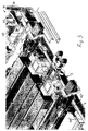
- stark schematisiert und skizzenhaft eine Perspektivansicht eines Ausführungsbeispieles eines erfindungsgemäßen Lastaufnahmemittels,
- Fig. 2
- eine schematische Perspektivansicht des Ausführungsbeispiels gemäß
Fig. 1 im Zusammenhang mit einem Regal eines Hoch-' regallagers, - Fig. 3
- eine Perspektivansicht einer Einzelheit des Ausführungsbeispiels gemäß
Fig. 2 im Bereich eines Stützelementes, - Fig. 4
- eine Seitenansicht des Lastaufnahmemittels während eines Einlagerungsvorganges,
- Fig. 5
- in gleicher Darstellung wie
Fig. 4 eine Einzelheit im Bereich eines Stützelementes vor Beginn eines Einlagerungs- oder Auslagerungsvorganges, - Fig. 6
- in gleicher Darstellung wie
Fig. 5 das Stützelement während eines Einlagerungs- bzw. Auslagerungsvorganges, - Fig. 7
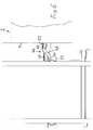
- eine stark schematisierte Seitenansicht eines mit verschiedenen Paletten belegten Regales einer Regalanordnung und
- Fig. 8
- eine Einzelheit des Ausführungsbeispiels gemäß
Fig. 2 im Bereich eines der Auflageelemente.
- Fig. 1
- highly schematic and sketchy a perspective view of an embodiment of a lifting device according to the invention,
- Fig. 2
- a schematic perspective view of the embodiment according to
Fig. 1 in connection with a shelf of a high rack warehouse, - Fig. 3
- a perspective view of a detail of the embodiment according to
Fig. 2 in the region of a supporting element, - Fig. 4
- a side view of the lifting device during a storage process,
- Fig. 5
- in the same representation as
Fig. 4 a detail in the area of a support element before the beginning of a storage or retrieval process, - Fig. 6
- in the same representation as
Fig. 5 the support element during a storage or removal process, - Fig. 7
- a highly schematic side view of a occupied with different pallets shelf of a shelf assembly and
- Fig. 8
- a detail of the embodiment according to
Fig. 2 in the area of one of the support elements.
In
Zum Anheben bzw. Absenken des Lastaufnahmemittels 4 sind Mittel zum Auf- und Abwickeln des Tragseiles 6 vorgesehen, die bei diesem Ausführungsbeispiel durch eine Wickeltrommel 8 gebildet sind, die mittels eines nicht dargestellten Elektromotors um eine Drehachse 10 drehantreibbar ist. Bei Benutzung werden die dem Tragseil 6 sowie den übrigen Tragseilen zugeordneten Wikkeltrommeln 8 synchron drehangetrieben, so daß entsprechend der jeweiligen Drehrichtung der Wickeltrommeln 8 das Lastaufnahmemittel 2 angehoben bzw. gesenkt wird. Auf diese Weise ist eine Hubachse (y-Achse) definiert. Die Wickeltrommeln 8 sind an einer krankatzenartigen Aufhängung angeordnet (nicht dargestellt), mittels derer das Lastaufnahmemittel 2 in x- und z-Richtung verfahrbar ist, so daß das Lastaufnahmemittel im Ergebnis dreidimensional relativ zu einer Regalanordnung (in
Um während eines Ein- bzw. Auslagerungsvorganges Lasten von dem Lastaufnahmemittel 2 zu einem Lagerplatz bzw. von einem Lagerplatz auf das Lastaufnahmemittel 2 zu bewegen, ist das Lastaufnahmemittel 2 mit einer geeigneten Lastaufnahmevorrichtung, beispielsweise einer Gabelanordnung oder einem Satellitenfahrzeug, versehen. Entsprechende Lastaufnahmevorrichtungen sind dem Fachmann allgemein bekannt und werden daher hier nicht näher erläutert.In order to move loads from the load receiving means 2 to a storage place or from a storage place to the load receiving means 2 during a loading and unloading operation, the load receiving means 2 is provided with a suitable load receiving device, for example a fork assembly or a satellite vehicle. Corresponding load bearing devices are generally known to the person skilled in the art and are therefore not explained in more detail here.
Das Lastaufnahmemittel weist ferner an gegenüberliegenden Längsrändern 12, 14 des Grundkörpers 4 angeordnete Stützelemente 16, 18, 20, 22 zur Abstützung des Grundkörpers 4 an der Regalanordnung während eines Ein- und Auslagerungsvorganges auf.The load-receiving means further comprises on opposite
Soweit nachfolgend lediglich eines der Stützelemente 16, 18, 20, 22 näher erläutert wird, sind die übrigen Stützelemente in ihrem Aufbau und in ihrer Funktion entsprechend ausgebildet und werden daher nicht näher erläutert.As far as only one of the
Das Stützelement 16 ist in Bezug auf den zugeordneten Längsrand 14 ein- bzw. ausfahrbar. Während eines Transportvorganges mit auf dem Lastaufnahmemittel 2 aufgenommener Last ist das Stützelement 16 eingefahren, so daß es bündig mit dem Längsrand 14 abschließt oder zum Inneren des Lastaufnahmemittels 2 gegenüber dem Längsrand 14 zurückspringt. Auf diese Weise ist vermieden, daß das Stützelement 16 während eines Transportvorganges, bei dem sich das Lastaufnahmemittel 2 vertikal und/oder horizontal durch eine Regalgasse bewegt, mit Teilen der Regalanordnung kollidiert.The
Demgegenüber steht das Stützelement 16 während eines Lastaufnahme- bzw. Abgabevorganges über den Längsrand 14 hervor, wie in
Erfindungsgemäß sind das Stützelement 16 sowie die weiteren Stützelemente 18, 20 und 22 entlang des jeweiligen Längsrandes 14 bzw. 12 verstellbar. Bei dem dargestellten Ausführungsbeispiel ist das Stützelement 16 entlang einer zu dem Längsrand 14 im wesentlichen parallel verlaufenden linearen Verstellachse, die in
Bei dem dargestellten Ausführungsbeispiel sind sämtliche Stützelemente 16, 18, 20, 22 jeweils ein- bzw. ausfahrbar sowie mittels eines zugeordneten Verstellantriebs entlang der linearen Verstellachse 28 verstellbar. Die Ansteuerung der Verstellantriebe erfolgt durch geeignete Steuerungsmittel. Die Steuerungsmittel können beispielsweise eine an dem Lastaufnahmemittel 2 angeordnete Steuerung aufweisen. Es ist erfindungsgemäß jedoch auch möglich, daß die Steuerungsmittel durch einen Zentralrechner eines Lagers, in dem das Lastaufnahmemittel 2 verwendet wird, gebildet ist.In the illustrated embodiment, all the
Durch die Steuerungsmittel ist einerseits das Ein-und Ausfahren der Stützelemente 16, 18, 20, 22 synchronisiert, und zwar derart, daß sich während des Transportes einer Last die Stützelemente 16, 18, 20, 22 im eingefahrenen Zustand befinden. Ferner ist eine Bewegung der Stützelemente 16, 18, 20, 22 entlang der Verstellachse 26 so synchronisiert, daß bezogen auf die Längsränder 12, 14 gegenüberliegend angeordnete Stützelemente 16 und 22 bzw. 18, 20 in Richtung des Doppelpfeiles 28 synchron zueinander verstellt werden.By the control means on the one hand, the retraction and extension of the
Ein Lastein- bzw. Auslagerungsvorgang vollzieht sich mittels des erfindungsgemäßen Lastaufnahmemittels 2 wie folgt:A load insertion or removal operation takes place by means of the load-receiving means 2 according to the invention as follows:
Zum Einlagern an einer Lastaufnahmestelle eines Lagers aufgenommenen Last wird das Lastaufnahmemittel 2 in x-, y- und z-Richtung so verfahren, daß es vor einem Lagerplatz, an dem die Last eingelagert werden soll, angeordnet ist. Wie in
Befindet sich das Lastaufnahmemittel 2 vor einem Lagerplatz, an dem eine auf dem Lastaufnahmemittel 2 aufgenommene Last eingelagert werden soll, so ist das Lastaufnahmemittel 2 in Vertikalrichtung zunächst so positioniert, daß sich die Stützelemente 20, 22 oberhalb des Profilelementes 32 befinden.The load-carrying
In dieser Position des Lastaufnahmemittels 2 werden die Stützelemente 20, 22 ausgefahren und das Lastaufnahmemittel 2 abgesenkt, so daß die Stützelemente 16, 18 auf dem Profilelement 32 zur Auflage gelangen und sich das Lastaufnahmemittel 2 somit mittels der Stützelemente 20, 22 auf dem Profilelement 32 abstützt.In this position, the load-receiving means 2, the
Der Abstand der Stützelemente 20, 22 in Längsrichtung des Profilelementes 32 ist hierbei so eingestellt, daß beim Ausfahren der Stützelemente 20, 22 eine Kollision mit Teilen der Regalanordnung 30 oder an Lagerplätzen der Regalanordnung 32 angeordneten Lasten vermieden ist. Dieser Vorgang wird weiter unten anhand von
Bei dem dargestellten Ausführungsbeispiel weist der Verstellantrieb 34 einen Schwenkhebel 36 auf, der mittels eines nicht dargestellten Elektromotors um eine Schwenkachse 38 schwenkbar ist. Mit dem der Schwenkachse 38 abgewandten Ende des Schwenkhebels 36 ist gelenkig und um eine zu der Schwenkachse 38 parallele Schwenkachse ein stangenartiges Element 40 verbunden, mit dessen der Schwenkachse 38 abgewandten Ende gelenkig eine Lasche verbunden ist (vgl. das Bezugszeichen 42' bei dem Stützelement 18), die ihrerseits entlang der linearen Verstellachse 26 verschiebefest mit dem Stützelement 16 verbunden ist.In the illustrated embodiment, the adjusting
Bei einem Verschwenken des Schwenkhebels 36 um die Schwenkachse 38 führt das Stützelement 16 somit entsprechend der Schwenkrichtung des Schwenkhebels 36 eine Bewegung entlang der linearen Verstellachse 26 in der einen oder anderen Richtung aus. Auf diese Weise ist die Position des Stützelementes 16 entlang des Längsrandes 14 einstellbar. Zum Ein- bzw. Ausfahren der Stützelemente 16 ist eine geeignete Verstellmechanik vorgesehen, die jedoch unabhängig von der Erfindung ist und daher hier nicht näher erläutert wird. Entsprechendes gilt auch für die Stützelemente 18, 20, 22.Upon pivoting of the
Soll mittels des erfindungsgemäßen Lastaufnahmemittels 2 die Euro-Palette 66 von dem Regalboden 64 entnommen werden, so werden die Stützelemente 16, 18 entlang ihrer linearen Bewegungsachse so zueinander verstellt, daß sich das Stützelement 16 in
Soll demgegenüber die Industriepalette 74 von dem Regalboden 72 entnommen werden, so würde die in
Während des zuvor beschriebenen Auslagerungsvorganges befindet sich das Lastaufnahmemittel 2 in einer Regalgasse der Regalanordnung 30. Die Stützelemente 20, 22 stützen sich hierbei auf der den Regalböden 64, 72 abgewandten Seite der Regalgasse an einem Profilelement der Regalanordnung 30 ab.During the removal process described above, the load-receiving means 2 is in a rack aisle of the
Aufgrund der erfindungsgemäß vorgesehenen Verstellbarkeit der Stützelemente 16, 18, 20, 22 jeweils entlang einer linearen Verstellachse ist mit dem erfindungsgemäßen Lastaufnahmemittel 2 eine Ein- und Auslagerung von Lasten in Regalanordnungen ermöglicht, in denen Lasten unterschiedlicher Abmessungen, beispielsweise Paletten unterschiedlicher Breite, eingelagert sind.Due to the inventively provided adjustability of the
Erfindungsgemäß kann eine Speichereinrichtung vorgesehen sein, in der Belegungsinformationen über die Belegung von Lagerplätzen der Regalanordnung abspeicherbar sind, wobei die Speichereinrichtung mit den Steuerungsmitteln derart in Datenübertragungsverbindung steht, daß in Abhängigkeit von Belegungsinformationen Verstellantriebe der Stützelemente 16, 18, 20, 22 durch die Steuerungsmittel ansteuerbar sind. Die Verstellung der Stützelemente 16, 18, 20, 22 kann beispielsweise erfolgen, während sich das Lastaufnahmemittel zu einem Lagerplatz bewegt, an dem bzw. von dem eine Last ein- bzw. ausgelagert werden soll.According to the invention, a memory device can be provided in which allocation information about the occupancy of storage bins of the rack arrangement can be stored, wherein the storage device is in data transmission connection with the control means in such a way that depending on allocation information Adjustment drives the
Es ist erfindungsgemäß auch möglich, daß vorzugsweise an dem Grundkörper des Lastaufnahmemittels Belegungserkennungsmittel vorgesehen sind zur Erkennung der Belegung von Lagerplätzen der Regalanordnung.It is also possible according to the invention that occupancy detection means are preferably provided on the main body of the load-receiving means for detecting the occupancy of storage spaces of the shelf arrangement.
Claims (12)
mit einem an Tragseilen aufgehängten Grundkörper und
mit an gegenüberliegenden Längsrändern des Grundkörpers angeordneten Stützelement zur Abstützung des Grundkörpers an der Regalanordnung während eines Ein- und Auslagerungsvorganges,
dadurch gekennzeichnet,
daß wenigstens eines der Stützelemente (16, 18, 20, 22) entlang des jeweiligen Längsrandes (12, 14) verstellbar ist und
daß dem Stützelement (16, 18, 20, 22) ein Verstellantrieb zugeordnet ist.Load-carrying means for loading and unloading loads to or from storage bins of a rack arrangement,
with a suspended on ropes body and
with supporting element arranged on opposite longitudinal edges of the basic body for supporting the basic body on the shelf arrangement during a loading and unloading process,
characterized,
in that at least one of the support elements (16, 18, 20, 22) is adjustable along the respective longitudinal edge (12, 14) and
that the adjusting element (16, 18, 20, 22) is associated with an adjusting drive.
Applications Claiming Priority (1)
| Application Number | Priority Date | Filing Date | Title |
|---|---|---|---|
| DE200820008350 DE202008008350U1 (en) | 2008-06-24 | 2008-06-24 | Load-receiving means for storage and retrieval of loads to or from storage bins of a shelf assembly |
Publications (2)
| Publication Number | Publication Date |
|---|---|
| EP2138427A1 true EP2138427A1 (en) | 2009-12-30 |
| EP2138427B1 EP2138427B1 (en) | 2012-07-11 |
Family
ID=41134649
Family Applications (1)
| Application Number | Title | Priority Date | Filing Date |
|---|---|---|---|
| EP20090006438 Active EP2138427B1 (en) | 2008-06-24 | 2009-05-13 | Load bearer for loading and unloading loads into or out of storage areas of a shelf assembly |
Country Status (2)
| Country | Link |
|---|---|
| EP (1) | EP2138427B1 (en) |
| DE (2) | DE202008008350U1 (en) |
Cited By (2)
| Publication number | Priority date | Publication date | Assignee | Title |
|---|---|---|---|---|
| CN112938282A (en) * | 2021-02-03 | 2021-06-11 | 优顶特技术有限公司 | Intelligent warehousing safety management system and device |
| WO2023197018A1 (en) * | 2022-04-13 | 2023-10-19 | Knapp Ag | Storage system and method for storing objects in such a storage system |
Families Citing this family (2)
| Publication number | Priority date | Publication date | Assignee | Title |
|---|---|---|---|---|
| DE102017119928A1 (en) | 2016-09-27 | 2018-03-29 | Westfalia Intralogistic Gmbh | logistics system |
| DE102019128778A1 (en) | 2019-05-29 | 2020-12-03 | Westfalia Intralogistic Gmbh | Storage system |
Citations (4)
| Publication number | Priority date | Publication date | Assignee | Title |
|---|---|---|---|---|
| DE2553221A1 (en) | 1975-11-27 | 1977-06-02 | Demag Ag | WAREHOUSE FACILITIES |
| DE3106137A1 (en) * | 1981-02-19 | 1982-09-09 | Adolf 5758 Fröndenberg Theobald | Device for fixing lifting tables and slide-in trucks in rack systems |
| WO2003040021A1 (en) | 2001-11-08 | 2003-05-15 | Krusche Lagertechnik Ag | Device for transversally moving a load suspension means in an overhead system for handling storage units |
| EP1925572A1 (en) * | 2006-11-22 | 2008-05-28 | Dreier Solutions GmbH | Shelf storage plant |
-
2008
- 2008-06-24 DE DE200820008350 patent/DE202008008350U1/en not_active Expired - Lifetime
- 2008-10-01 DE DE102008049991A patent/DE102008049991A1/en not_active Withdrawn
-
2009
- 2009-05-13 EP EP20090006438 patent/EP2138427B1/en active Active
Patent Citations (5)
| Publication number | Priority date | Publication date | Assignee | Title |
|---|---|---|---|---|
| DE2553221A1 (en) | 1975-11-27 | 1977-06-02 | Demag Ag | WAREHOUSE FACILITIES |
| DE3106137A1 (en) * | 1981-02-19 | 1982-09-09 | Adolf 5758 Fröndenberg Theobald | Device for fixing lifting tables and slide-in trucks in rack systems |
| WO2003040021A1 (en) | 2001-11-08 | 2003-05-15 | Krusche Lagertechnik Ag | Device for transversally moving a load suspension means in an overhead system for handling storage units |
| US20050065636A1 (en) * | 2001-11-08 | 2005-03-24 | Krusche Lagertechnik Ag | Load receiving means for a system for operating storage units |
| EP1925572A1 (en) * | 2006-11-22 | 2008-05-28 | Dreier Solutions GmbH | Shelf storage plant |
Cited By (2)
| Publication number | Priority date | Publication date | Assignee | Title |
|---|---|---|---|---|
| CN112938282A (en) * | 2021-02-03 | 2021-06-11 | 优顶特技术有限公司 | Intelligent warehousing safety management system and device |
| WO2023197018A1 (en) * | 2022-04-13 | 2023-10-19 | Knapp Ag | Storage system and method for storing objects in such a storage system |
Also Published As
| Publication number | Publication date |
|---|---|
| DE102008049991A1 (en) | 2009-12-31 |
| DE202008008350U1 (en) | 2009-11-12 |
| EP2138427B1 (en) | 2012-07-11 |
Similar Documents
| Publication | Publication Date | Title |
|---|---|---|
| EP3286111B1 (en) | Method for transferring part-load consignments to a storage rack for storage, and storage system | |
| EP2794432B1 (en) | Rack storage system and method for operating it | |
| EP1695925B1 (en) | Shelf store and method for transferring goods in a shelf store | |
| EP2234904B1 (en) | Method for storing loading aids and transporting device | |
| WO2017144055A1 (en) | Telescopic drive, stacker crane comprising same and operating method and use therefor | |
| AT511490A1 (en) | BAY WAREHOUSE SYSTEM | |
| EP1988053B1 (en) | Floor conveyor for transporting containers | |
| EP2138427B1 (en) | Load bearer for loading and unloading loads into or out of storage areas of a shelf assembly | |
| EP2746193B1 (en) | Vehicle for a warehouse, stacker crane, warehouse and corresponding method | |
| DE102006035049B4 (en) | Method for storing and retrieving piece goods, in particular beverage crates, and storage system therefor | |
| DE102008064533A1 (en) | Load-receiving device for a stacker crane, conveyor with a stacker crane and method for operating a stacker crane | |
| EP3023364A1 (en) | Stacker crane and storage system | |
| DE102017107695A1 (en) | Industrial truck with pushing device | |
| EP2170755B1 (en) | Transporting apparatus for transporting loads to storage places, in particular in a high-bay warehouse | |
| EP2829502B1 (en) | Load bearing device for a rack retrieval system | |
| EP0697368B1 (en) | Pick-up attachment for pallets | |
| DE4238322C2 (en) | A conveyor | |
| EP2318291B1 (en) | Storage arrangement for placing items to be stored in storage locations and removing said items therefrom | |
| DE10241347B4 (en) | Storage facility for storage and retrieval of containers or the like in or out of a shelf | |
| EP0572846B1 (en) | Ancillary equipment for lifting trucks | |
| DE19634216C2 (en) | Load suspension device for double-deep storage or retrieval of palletized loading units | |
| DE102016117941A1 (en) | Telescopic drive, a comprehensive storage and retrieval unit and operating method and use thereof | |
| DE4013859C2 (en) | ||
| DE4111523A1 (en) | Two-tiered variable loading and storage height transport vehicle - includes movable undercarriage and lifting forks | |
| EP1862405B1 (en) | Method for gripping piece goods using gripper devices of an input and output system and device therefor |
Legal Events
| Date | Code | Title | Description |
|---|---|---|---|
| PUAI | Public reference made under article 153(3) epc to a published international application that has entered the european phase |
Free format text: ORIGINAL CODE: 0009012 |
|
| AK | Designated contracting states |
Kind code of ref document: A1 Designated state(s): AT BE BG CH CY CZ DE DK EE ES FI FR GB GR HR HU IE IS IT LI LT LU LV MC MK MT NL NO PL PT RO SE SI SK TR |
|
| 17P | Request for examination filed |
Effective date: 20100630 |
|
| GRAP | Despatch of communication of intention to grant a patent |
Free format text: ORIGINAL CODE: EPIDOSNIGR1 |
|
| GRAS | Grant fee paid |
Free format text: ORIGINAL CODE: EPIDOSNIGR3 |
|
| GRAA | (expected) grant |
Free format text: ORIGINAL CODE: 0009210 |
|
| AK | Designated contracting states |
Kind code of ref document: B1 Designated state(s): AT BE BG CH CY CZ DE DK EE ES FI FR GB GR HR HU IE IS IT LI LT LU LV MC MK MT NL NO PL PT RO SE SI SK TR |
|
| REG | Reference to a national code |
Ref country code: GB Ref legal event code: FG4D Free format text: NOT ENGLISH |
|
| REG | Reference to a national code |
Ref country code: CH Ref legal event code: EP |
|
| REG | Reference to a national code |
Ref country code: AT Ref legal event code: REF Ref document number: 566008 Country of ref document: AT Kind code of ref document: T Effective date: 20120715 |
|
| REG | Reference to a national code |
Ref country code: IE Ref legal event code: FG4D Free format text: LANGUAGE OF EP DOCUMENT: GERMAN |
|
| REG | Reference to a national code |
Ref country code: DE Ref legal event code: R096 Ref document number: 502009004049 Country of ref document: DE Effective date: 20120830 |
|
| REG | Reference to a national code |
Ref country code: NL Ref legal event code: VDEP Effective date: 20120711 |
|
| REG | Reference to a national code |
Ref country code: LT Ref legal event code: MG4D Effective date: 20120711 |
|
| PG25 | Lapsed in a contracting state [announced via postgrant information from national office to epo] |
Ref country code: HR Free format text: LAPSE BECAUSE OF FAILURE TO SUBMIT A TRANSLATION OF THE DESCRIPTION OR TO PAY THE FEE WITHIN THE PRESCRIBED TIME-LIMIT Effective date: 20120711 Ref country code: LT Free format text: LAPSE BECAUSE OF FAILURE TO SUBMIT A TRANSLATION OF THE DESCRIPTION OR TO PAY THE FEE WITHIN THE PRESCRIBED TIME-LIMIT Effective date: 20120711 Ref country code: CY Free format text: LAPSE BECAUSE OF FAILURE TO SUBMIT A TRANSLATION OF THE DESCRIPTION OR TO PAY THE FEE WITHIN THE PRESCRIBED TIME-LIMIT Effective date: 20120711 Ref country code: FI Free format text: LAPSE BECAUSE OF FAILURE TO SUBMIT A TRANSLATION OF THE DESCRIPTION OR TO PAY THE FEE WITHIN THE PRESCRIBED TIME-LIMIT Effective date: 20120711 Ref country code: NO Free format text: LAPSE BECAUSE OF FAILURE TO SUBMIT A TRANSLATION OF THE DESCRIPTION OR TO PAY THE FEE WITHIN THE PRESCRIBED TIME-LIMIT Effective date: 20121011 Ref country code: IS Free format text: LAPSE BECAUSE OF FAILURE TO SUBMIT A TRANSLATION OF THE DESCRIPTION OR TO PAY THE FEE WITHIN THE PRESCRIBED TIME-LIMIT Effective date: 20121111 |
|
| PG25 | Lapsed in a contracting state [announced via postgrant information from national office to epo] |
Ref country code: GR Free format text: LAPSE BECAUSE OF FAILURE TO SUBMIT A TRANSLATION OF THE DESCRIPTION OR TO PAY THE FEE WITHIN THE PRESCRIBED TIME-LIMIT Effective date: 20121012 Ref country code: SE Free format text: LAPSE BECAUSE OF FAILURE TO SUBMIT A TRANSLATION OF THE DESCRIPTION OR TO PAY THE FEE WITHIN THE PRESCRIBED TIME-LIMIT Effective date: 20120711 Ref country code: SI Free format text: LAPSE BECAUSE OF FAILURE TO SUBMIT A TRANSLATION OF THE DESCRIPTION OR TO PAY THE FEE WITHIN THE PRESCRIBED TIME-LIMIT Effective date: 20120711 Ref country code: PL Free format text: LAPSE BECAUSE OF FAILURE TO SUBMIT A TRANSLATION OF THE DESCRIPTION OR TO PAY THE FEE WITHIN THE PRESCRIBED TIME-LIMIT Effective date: 20120711 Ref country code: PT Free format text: LAPSE BECAUSE OF FAILURE TO SUBMIT A TRANSLATION OF THE DESCRIPTION OR TO PAY THE FEE WITHIN THE PRESCRIBED TIME-LIMIT Effective date: 20121112 Ref country code: LV Free format text: LAPSE BECAUSE OF FAILURE TO SUBMIT A TRANSLATION OF THE DESCRIPTION OR TO PAY THE FEE WITHIN THE PRESCRIBED TIME-LIMIT Effective date: 20120711 |
|
| PG25 | Lapsed in a contracting state [announced via postgrant information from national office to epo] |
Ref country code: NL Free format text: LAPSE BECAUSE OF FAILURE TO SUBMIT A TRANSLATION OF THE DESCRIPTION OR TO PAY THE FEE WITHIN THE PRESCRIBED TIME-LIMIT Effective date: 20120711 |
|
| PG25 | Lapsed in a contracting state [announced via postgrant information from national office to epo] |
Ref country code: EE Free format text: LAPSE BECAUSE OF FAILURE TO SUBMIT A TRANSLATION OF THE DESCRIPTION OR TO PAY THE FEE WITHIN THE PRESCRIBED TIME-LIMIT Effective date: 20120711 Ref country code: DK Free format text: LAPSE BECAUSE OF FAILURE TO SUBMIT A TRANSLATION OF THE DESCRIPTION OR TO PAY THE FEE WITHIN THE PRESCRIBED TIME-LIMIT Effective date: 20120711 Ref country code: ES Free format text: LAPSE BECAUSE OF FAILURE TO SUBMIT A TRANSLATION OF THE DESCRIPTION OR TO PAY THE FEE WITHIN THE PRESCRIBED TIME-LIMIT Effective date: 20121022 Ref country code: CZ Free format text: LAPSE BECAUSE OF FAILURE TO SUBMIT A TRANSLATION OF THE DESCRIPTION OR TO PAY THE FEE WITHIN THE PRESCRIBED TIME-LIMIT Effective date: 20120711 Ref country code: RO Free format text: LAPSE BECAUSE OF FAILURE TO SUBMIT A TRANSLATION OF THE DESCRIPTION OR TO PAY THE FEE WITHIN THE PRESCRIBED TIME-LIMIT Effective date: 20120711 |
|
| PLBE | No opposition filed within time limit |
Free format text: ORIGINAL CODE: 0009261 |
|
| STAA | Information on the status of an ep patent application or granted ep patent |
Free format text: STATUS: NO OPPOSITION FILED WITHIN TIME LIMIT |
|
| PG25 | Lapsed in a contracting state [announced via postgrant information from national office to epo] |
Ref country code: SK Free format text: LAPSE BECAUSE OF FAILURE TO SUBMIT A TRANSLATION OF THE DESCRIPTION OR TO PAY THE FEE WITHIN THE PRESCRIBED TIME-LIMIT Effective date: 20120711 Ref country code: IT Free format text: LAPSE BECAUSE OF FAILURE TO SUBMIT A TRANSLATION OF THE DESCRIPTION OR TO PAY THE FEE WITHIN THE PRESCRIBED TIME-LIMIT Effective date: 20120711 |
|
| 26N | No opposition filed |
Effective date: 20130412 |
|
| PG25 | Lapsed in a contracting state [announced via postgrant information from national office to epo] |
Ref country code: BG Free format text: LAPSE BECAUSE OF FAILURE TO SUBMIT A TRANSLATION OF THE DESCRIPTION OR TO PAY THE FEE WITHIN THE PRESCRIBED TIME-LIMIT Effective date: 20121011 |
|
| REG | Reference to a national code |
Ref country code: DE Ref legal event code: R097 Ref document number: 502009004049 Country of ref document: DE Effective date: 20130412 |
|
| BERE | Be: lapsed |
Owner name: WESTFALIA INTRALOGISTIC G.M.B.H. Effective date: 20130531 |
|
| PG25 | Lapsed in a contracting state [announced via postgrant information from national office to epo] |
Ref country code: MC Free format text: LAPSE BECAUSE OF FAILURE TO SUBMIT A TRANSLATION OF THE DESCRIPTION OR TO PAY THE FEE WITHIN THE PRESCRIBED TIME-LIMIT Effective date: 20120711 |
|
| REG | Reference to a national code |
Ref country code: IE Ref legal event code: MM4A |
|
| PG25 | Lapsed in a contracting state [announced via postgrant information from national office to epo] |
Ref country code: BE Free format text: LAPSE BECAUSE OF NON-PAYMENT OF DUE FEES Effective date: 20130531 |
|
| PG25 | Lapsed in a contracting state [announced via postgrant information from national office to epo] |
Ref country code: IE Free format text: LAPSE BECAUSE OF NON-PAYMENT OF DUE FEES Effective date: 20130513 |
|
| PG25 | Lapsed in a contracting state [announced via postgrant information from national office to epo] |
Ref country code: MT Free format text: LAPSE BECAUSE OF FAILURE TO SUBMIT A TRANSLATION OF THE DESCRIPTION OR TO PAY THE FEE WITHIN THE PRESCRIBED TIME-LIMIT Effective date: 20120711 |
|
| PG25 | Lapsed in a contracting state [announced via postgrant information from national office to epo] |
Ref country code: TR Free format text: LAPSE BECAUSE OF FAILURE TO SUBMIT A TRANSLATION OF THE DESCRIPTION OR TO PAY THE FEE WITHIN THE PRESCRIBED TIME-LIMIT Effective date: 20120711 |
|
| PG25 | Lapsed in a contracting state [announced via postgrant information from national office to epo] |
Ref country code: MK Free format text: LAPSE BECAUSE OF FAILURE TO SUBMIT A TRANSLATION OF THE DESCRIPTION OR TO PAY THE FEE WITHIN THE PRESCRIBED TIME-LIMIT Effective date: 20120711 Ref country code: HU Free format text: LAPSE BECAUSE OF FAILURE TO SUBMIT A TRANSLATION OF THE DESCRIPTION OR TO PAY THE FEE WITHIN THE PRESCRIBED TIME-LIMIT; INVALID AB INITIO Effective date: 20090513 Ref country code: LU Free format text: LAPSE BECAUSE OF NON-PAYMENT OF DUE FEES Effective date: 20130513 |
|
| REG | Reference to a national code |
Ref country code: FR Ref legal event code: PLFP Year of fee payment: 8 |
|
| REG | Reference to a national code |
Ref country code: DE Ref legal event code: R082 Ref document number: 502009004049 Country of ref document: DE Representative=s name: WAGNER, CARSTEN, DIPL.-ING. (UNIV.), DE |
|
| REG | Reference to a national code |
Ref country code: FR Ref legal event code: PLFP Year of fee payment: 9 |
|
| REG | Reference to a national code |
Ref country code: FR Ref legal event code: PLFP Year of fee payment: 10 |
|
| PGFP | Annual fee paid to national office [announced via postgrant information from national office to epo] |
Ref country code: FR Payment date: 20200529 Year of fee payment: 12 |
|
| PGFP | Annual fee paid to national office [announced via postgrant information from national office to epo] |
Ref country code: GB Payment date: 20200526 Year of fee payment: 12 |
|
| GBPC | Gb: european patent ceased through non-payment of renewal fee |
Effective date: 20210513 |
|
| REG | Reference to a national code |
Ref country code: DE Ref legal event code: R081 Ref document number: 502009004049 Country of ref document: DE Owner name: WESTFALIA LOGISTICS SOLUTIONS EUROPE GMBH & CO, DE Free format text: FORMER OWNER: WESTFALIA INTRALOGISTIC GMBH, 33428 HARSEWINKEL, DE |
|
| PG25 | Lapsed in a contracting state [announced via postgrant information from national office to epo] |
Ref country code: GB Free format text: LAPSE BECAUSE OF NON-PAYMENT OF DUE FEES Effective date: 20210513 |
|
| PG25 | Lapsed in a contracting state [announced via postgrant information from national office to epo] |
Ref country code: FR Free format text: LAPSE BECAUSE OF NON-PAYMENT OF DUE FEES Effective date: 20210531 |
|
| REG | Reference to a national code |
Ref country code: AT Ref legal event code: PC Ref document number: 566008 Country of ref document: AT Kind code of ref document: T Owner name: WESTFALIA LOGISTICS SOLUTIONS EUROPE GMBH & CO, DE Effective date: 20220719 |
|
| REG | Reference to a national code |
Ref country code: DE Ref legal event code: R082 Ref document number: 502009004049 Country of ref document: DE Representative=s name: HOEFER & PARTNER PATENTANWAELTE MBB, DE |
|
| PGFP | Annual fee paid to national office [announced via postgrant information from national office to epo] |
Ref country code: DE Payment date: 20230526 Year of fee payment: 15 Ref country code: CH Payment date: 20230605 Year of fee payment: 15 |
|
| PGFP | Annual fee paid to national office [announced via postgrant information from national office to epo] |
Ref country code: AT Payment date: 20230519 Year of fee payment: 15 |