EP2138362B1 - Articulating device for a front flap of a motor vehicle with an impact protection device and/or pedestrian protection device - Google Patents
Articulating device for a front flap of a motor vehicle with an impact protection device and/or pedestrian protection device Download PDFInfo
- Publication number
- EP2138362B1 EP2138362B1 EP09007380A EP09007380A EP2138362B1 EP 2138362 B1 EP2138362 B1 EP 2138362B1 EP 09007380 A EP09007380 A EP 09007380A EP 09007380 A EP09007380 A EP 09007380A EP 2138362 B1 EP2138362 B1 EP 2138362B1
- Authority
- EP
- European Patent Office
- Prior art keywords
- hinge part
- bonnet
- lower hinge
- stop face
- region
- Prior art date
- Legal status (The legal status is an assumption and is not a legal conclusion. Google has not performed a legal analysis and makes no representation as to the accuracy of the status listed.)
- Active
Links
Images

Classifications
-
- B—PERFORMING OPERATIONS; TRANSPORTING
- B60—VEHICLES IN GENERAL
- B60R—VEHICLES, VEHICLE FITTINGS, OR VEHICLE PARTS, NOT OTHERWISE PROVIDED FOR
- B60R21/00—Arrangements or fittings on vehicles for protecting or preventing injuries to occupants or pedestrians in case of accidents or other traffic risks
- B60R21/34—Protecting non-occupants of a vehicle, e.g. pedestrians
- B60R21/38—Protecting non-occupants of a vehicle, e.g. pedestrians using means for lifting bonnets
Definitions
- the invention relates to a hinge device for a front flap of a motor vehicle with an impact protection device and / or pedestrian protection device, with the features specified in the preamble of claim 1.
- Such a hinge device has in the DE 10 2007 033 325 A1 a relative to the body of the motor vehicle pivotable lower hinge part and connected to the front flap of the motor vehicle upper hinge part, which are pivotally connected via a connecting axis and normally fixed to each other via a shear pin.
- the adjusting device is to be dimensioned correspondingly strong.
- the actuating device Due to the force application of the adjusting device on the upper hinge part or on the front flap, it is necessary that the actuating device has an actuating element cooperating with the upper hinge part or the front flap, one of the articulation point of the actuating element on the front flap or on the upper hinge part performs corresponding adjustment.
- the adjusting device adjusting the front door in the protective layer in which the dissolved from the lower hinge part upper hinge part relative to the lower hinge part pivots about the connecting axis, is to apply a much lower than the shearing of the shear bolt of the adjusting device force.
- the length of the actuator is essentially determined by the adjustment of the control element and limits the available space for other components accordingly.
- the DE 10 2005 022 924 A1 provides a hinge device in particular for a front door of a motor vehicle with two pivotally connected hinge parts, of which a hinge part is adjustable via two pivotal lever forming a four-bar relative to the body of the motor vehicle.
- the other hinge part is connected to the front flap.
- the two hinge parts are normally locked to each other via a locking device with a pawl.
- An actuator can unlock in an accidental impact on the front flap, the pawl on a pivotable latch release and in cooperation with a pivot lever of the four-bar levered down the front flap in the direction of their protective layer and thus translate force translated.
- the pawl should not fix the two hinge parts to each other without backlash, so that the hinge parts are likely to perform noisy disturbing movements during normal driving.
- the invention is based on the object to provide a hinge device with the features in the preamble of claim 1, which requires a smaller space and is claimed evenly when lifting the front flap in the protective layer.
- the hinge device according to the invention for a front flap of a motor vehicle with an impact protection device and / or pedestrian protection device has a lower hinge part, which is pivotable on the one hand to a real or virtual stationary or portable pivot axis relative to the body of the motor vehicle and on the other hand pivotable about a connecting axis with a front flap attached upper hinge part is connected.
- the lower and upper hinge part are connected at a distance from the connecting axis via a shear pin which engages in an opening in the lower hinge part and in an opening aligned with the receiving opening in the upper hinge part.
- the adjusting device has an actuating element which, in the event of an accidental or imminent impact on the front flap, is displaced by the adjusting device on the upper hinge part or on the front flap, shearing off the shear pin, and then raising at least a portion of the front flap in the direction of the protective layer of the front flap causes.
- the actuator acts only about until shearing the shear pin or something moreover with the front flap or with the upper hinge part together.
- the actuator of the actuator comes to the lower hinge part to the plant and subsequently causes now with the lower hinge part cooperative hubübernote a lifting at least a portion of the front flap in the direction of the raised protective layer.
- a pretensioned spring part can act as a supportive force or lift at least one relevant area of the front flap into the protective layer in a last adjustment range without the adjusting device.
- the actuator of the actuator performs after shearing the shear bolt against theêtnverstellweg the shearing of the shear bolt effective force application point of the control element on the front flap or at the upper hinge part much smaller adjustment, which corresponds to the adjustment of the force application point of the control element on the lower hinge part.
- the actuating element according to the path reduction is force-translated and thus more stressed, so that overall when lifting the front flap in the protective layer results in a more uniform loading of the control element. Due to the smaller displacement of the actuating element, the size of the actuating device is correspondingly reduced, whereby the actuating device does not or less restricts an arrangement of other components.
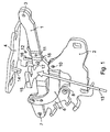
- Hinge device shown is provided for the adjustable support of a rear lateral region of a front flap of a motor vehicle and has for this purpose a lower hinge part 1.
- This hinge part 1 is pivotally connected on the one hand to a virtual spatially displaceable pivot axis relative to the bodywork of the motor vehicle or to a console 2 arranged thereon and, on the other hand, about a connecting axis 3 to an upper hinge part 4 fastened to the front flap.
- the virtual spatially variable transverse axis is formed in the embodiment by two unequal length pivoting lever 5, 6, which form a four-bar linkage with the lower hinge part 1 as a coupling element, wherein the pivot lever 5, 6 each about an axis 7, 8 and 9, 10 pivotally on the one hand articulated at different locations on the body of the motor vehicle or on a console 2 attached thereto and on the other hand at different locations on the lower hinge part 1.
- the pivot levers 5, 6 In the closed position of the front door, in which the upper and lower hinge part 1, 4 are in the normal position, the pivot levers 5, 6 from their body-side pivot points 8, 10 directed backwards above, the upper pivot lever 6 is longer than the lower pivot lever 5 is formed.
- the lower hinge part 1 protrudes beyond the articulation points 7, 9 of the pivoting levers 5, 6 at the lower hinge part 1 forwards and has at this front area the connecting axle 3, on which the upper hinge part 4 is pivotably articulated is. All axles 3, 7 to 10 extend in the vehicle transverse direction.
- the upper hinge part 4 extends substantially from the connection axis 3 to the rear.
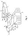
- the lower 1 and upper hinge part 4 are connected at a distance behind the connection axis 3 via a shear pin, not shown, in a in the FIGS. 1 and 3 recognizable opening in the lower hinge part 1 and in an opening 11 in alignment and in the FIGS. 1 and 3 also recognizable receiving opening 12 in the upper hinge part 4 engages.
- closed front flap is locked at its front by at least one lock.
- the front flap After opening the at least one lock, the front flap can be pivoted upwards and possibly slightly to the rear around the virtual movable swivel axis formed by the two pivoting levers 5, 6 in the rear region of the front flap, the upper and lower hinge parts 1, 4 passing over the Shear bolts, not shown, each remain connected to each other in their normal position.
- the hinge device has an in Fig. 1 merely indicated by a long arrow actuator 13 with an actuator, not shown, which is detected in an accidental occurred or imminent impact on the front flap, which is detected for example by at least one sensor on one of the underside of the upper hinge part 4 downwardly projecting projection 14th a shearing off the shear bolt force and then raising the rear portion of the front door in the direction of the FIGS. 1 and 3 shown causes situation in which the front door connected to the upper hinge part 4 is in its protective position.
- the front region of the front flap remains locked by the at least one lock, not shown in the figures, and can be pivoted, for example, only around a latch bolt engaged behind by a rotary latch, wherein the rotary latch is locked by a pawl.
- the actuator 13 of the actuator is in the embodiment, a piston rod of an actuator 13 which is axially displaceably arranged in a cylinder of the actuator 13 and with a protruding from the cylinder area or head area shearing the shear pin shear force on the front flap or at the top Hinge part 4 or on which from the bottom of the upper hinge part 4 downwardly projecting projection 14 causes.
- a stop surface formed immediately or after a slight lifting of the lower hinge part 1 in the direction of the FIGS. 1 and 3 shown position after shearing the shear pin on a formed by a fork-shaped support arm 15 of the lower hinge part 1 counter stop surface for Plant comes and cooperating with the counter stop surface lifting the lower hinge part 1 in the direction of the FIGS. 1 and 3 shown causes situation in which the front door connected to the upper hinge part 4 is in its protective position.
- the last adjustment movement of the rear area of the front flap into the protective layer can be assisted by a prestressed spring part or can be brought about without significant involvement of the adjusting device.
- the plane or possibly curved abutment surface of the piston rod and / or the flat or possibly curved counter-abutment surface 15 of the lower hinge part 4, at least in the region in which the abutment surface cooperates with the Jacobanschal Structure, have such a tendency that from the actuator 13 via the stop surface and the counter stop surface 15 transmitted force substantially in the axial direction of the actuator 13 extends.
- the front portion of the front flap is held by the at least one lock such that the rear portion of the front flap is substantially adjustable in the height direction such that the rear portion of the front flap between the closed position and protective position of the front flap adjusted or the front door can be swiveled accordingly.
- an impact protection device (not shown) and / or pedestrian protection device can cushion and / or dampen an accidental impact on the front flap.
- the pivot angle range of the upper hinge part 4 relative to the lower hinge part 1 is limited in the embodiment in at least one pivoting direction about the connecting axis 3 via a pin / slot guide, wherein in the FIGS. 1 to 3 the curved about the connecting axis slot of the pin / slot guide and in the FIGS. 1 and 3 which are arranged in a pin receptacle 17 in the lower hinge part 1 pin 18 of the pin / slot connection can be seen.
- the invention can be realized deviating from the single embodiment.
- the lower hinge part may be a real or virtual stationary or movable pivot axis relative to the body of the motor vehicle or a component supported thereon or fastened thereto, for example a console, be arranged pivotally.
- the real or virtual stationary or movable pivot axis can be realized in very different ways, at least one skilled in the art.
- the connecting axis, on which the lower hinge part is pivotably connected to the upper hinge part can be provided at any point of the hinge parts, in which, for example, the upper hinge part extends at least partially from the connection axis to the front.
- the actuator of the actuator When adjusting the front flap in the protective layer, the actuator of the actuator preferably comes immediately or soon after the shearing of the shear bolt on the lower hinge part to the plant to total on a shortest possible stroke of the actuator of the actuator a complete or at least partial displacement of the front door in the direction their raised protective layer effect.
- a short stroke of the actuating element allows a small size of the adjusting device, whereby the space required for other components space is not limited or less.
- a further element for example, at least provide a biased spring element, which then reached from the actuator, raised in the direction of the protective layer position of the front flap a complete displacement of the front door effected in the protective layer.
- the hinge device or a lock locking the front flap in its closed position is provided in a side region of the front flap, a component which is preferably identical or comparable to the hinge device or the lock is normally located on the laterally opposite side of the front flap, so that preferably symmetrical relationships present to a vertical vehicle longitudinal plane.
- the hinge device can be arranged in the front or rear, possibly lateral region of the front flap. If the closed front door is to be locked, for example, by at least one front, possibly lateral lock, or at least fixed in one direction, for example vertically, then the front door in the area of the lock can be raised when the front door is raised via the adjusting device or, if applicable, the actuator into the protective position remain locked or fixed by the lock. In this case, an elevation of the front flap into the protective layer essentially takes place in a region of the front flap which is remote from the lock. Likewise, when raising into the protective layer, the front and rear area of the front flap can be raised.
Abstract
Description
Die Erfindung betrifft eine Scharniereinrichtung für eine Frontklappe eines Kraftfahrzeugs mit einer Aufschlagschutzeinrichtung und/oder Fußgängerschutzeinrichtung, mit den im Oberbegriff des Patentanspruches 1 angegebenen Merkmalen.The invention relates to a hinge device for a front flap of a motor vehicle with an impact protection device and / or pedestrian protection device, with the features specified in the preamble of
Eine derartige Scharniereinrichtung weist in der
Die
Der Erfindung liegt die Aufgabe zu Grunde, eine Scharniereinrichtung mit den Merkmalen im Oberbegriff des Patentanspruches 1 anzugeben, die einen geringeren Bauraum erfordert und beim Anheben der Frontklappe in die Schutzlage gleichmäßiger beansprucht ist.The invention is based on the object to provide a hinge device with the features in the preamble of
Diese Aufgabe ist durch die Merkmale im Patentanspruch 1 gelöst. Vorteilhafte Ausgestaltungen der Erfindung sind den Unteransprüchen entnehmbar.This object is solved by the features in
Die erfindungsgemäße Scharniereinrichtung für eine Frontklappe eines Kraftfahrzeugs mit einer Aufschlagschutzeinrichtung und/oder Fußgängerschutzeinrichtung weist ein unteres Scharnierteil auf, das einerseits um eine reelle oder virtuelle ortsfeste oder ortsveränderliche Schwenkachse gegenüber der Karosserie des Kraftfahrzeugs schwenkbar ist und andererseits um eine Verbindungsachse schwenkbar mit einem an der Frontklappe befestigten oberen Scharnierteil verbunden ist. In einer Normallage sind das untere und obere Scharnierteil in einem Abstand von der Verbindungsachse über einen Scherbolzen verbunden, der in eine Öffnung im unteren Scharnierteil und in eine zur Öffnung fluchtende Aufnahmeöffnung im oberen Scharnierteil eingreift. Die Stelleinrichtung weist ein Stellelement auf, das bei einem unfallbedingt eingetretenen oder bevorstehenden Aufprall auf die Frontklappe von der Stelleinrichtung verstellt an dem oberen Scharnierteil oder an der Frontklappe eine den Scherbolzen abscherende Kraft und anschließend ein Anheben zumindest eines Bereiches der Frontklappe in Richtung der Schutzlage der Frontklappe bewirkt. Hierzu wirkt das Stellelement lediglich etwa bis zum Abscheren des Scherbolzens oder etwas darüber hinaus mit der Frontklappe oder mit dem oberen Scharnierteil zusammen. Sofort oder mehr oder weniger kurz nach dem Abscheren des Bolzens kommt das Stellelement der Stelleinrichtung an dem unteren Scharnierteil zur Anlage und bewirkt nachfolgend nun mit dem unteren Scharnierteil zusammen wirkend hubübersetzt ein Anheben zumindest eines Bereiches der Frontklappe in Richtung der angehobenen Schutzlage. Ein vorgespanntes Federteil kann dabei Kraft unterstützend wirken oder in einem letzten Verstellbereich ohne die Stelleinrichtung zumindest einen betreffenden Bereich der Frontklappe in die Schutzlage anheben. Das Stellelement der Stelleinrichtung führt nach dem Abscheren des Scherbolzens einen gegenüber dem Höhenverstellweg der beim Abscheren des Scherbolzens wirksamen Kraftangriffsstelle des Stellelements an der Frontklappe bzw. an dem oberen Scharnierteil wesentlich geringeren Verstellweg aus, der dem Verstellweg der Kraftangriffsstelle des Stellelements an dem unteren Scharnierteil entspricht. Auf diesem geringeren Verstellweg der Kraftangriffsstelle des Stellelements an dem unteren Scharnierteil ist das Stellelement entsprechend der Weguntersetzung kraftübersetzt und damit stärker beansprucht, so dass sich insgesamt beim Anheben der Frontklappe in die Schutzlage eine gleichmäßigere Beanspruchung des Stellelements ergibt. Durch den geringeren Verstellweg des Stellelements ist die Baugröße der Stelleinrichtung entsprechend vermindert, wodurch die Stelleinrichtung eine Anordnung anderer Bauteile nicht oder weniger einschränkt.The hinge device according to the invention for a front flap of a motor vehicle with an impact protection device and / or pedestrian protection device has a lower hinge part, which is pivotable on the one hand to a real or virtual stationary or portable pivot axis relative to the body of the motor vehicle and on the other hand pivotable about a connecting axis with a front flap attached upper hinge part is connected. In a Normal position, the lower and upper hinge part are connected at a distance from the connecting axis via a shear pin which engages in an opening in the lower hinge part and in an opening aligned with the receiving opening in the upper hinge part. The adjusting device has an actuating element which, in the event of an accidental or imminent impact on the front flap, is displaced by the adjusting device on the upper hinge part or on the front flap, shearing off the shear pin, and then raising at least a portion of the front flap in the direction of the protective layer of the front flap causes. For this purpose, the actuator acts only about until shearing the shear pin or something moreover with the front flap or with the upper hinge part together. Immediately or more or less shortly after the shearing of the bolt, the actuator of the actuator comes to the lower hinge part to the plant and subsequently causes now with the lower hinge part cooperative hubübersetzt a lifting at least a portion of the front flap in the direction of the raised protective layer. A pretensioned spring part can act as a supportive force or lift at least one relevant area of the front flap into the protective layer in a last adjustment range without the adjusting device. The actuator of the actuator performs after shearing the shear bolt against the Höhenverstellweg the shearing of the shear bolt effective force application point of the control element on the front flap or at the upper hinge part much smaller adjustment, which corresponds to the adjustment of the force application point of the control element on the lower hinge part. At this lower displacement of the force application point of the actuating element on the lower hinge part, the actuating element according to the path reduction is force-translated and thus more stressed, so that overall when lifting the front flap in the protective layer results in a more uniform loading of the control element. Due to the smaller displacement of the actuating element, the size of the actuating device is correspondingly reduced, whereby the actuating device does not or less restricts an arrangement of other components.
Ein Ausführungsbeispiel der Erfindung wird anhand einer Zeichnung näher erläutert. Es zeigen
- Fig. 1
- eine perspektivische Ansicht von der in einer hochgestellten Lage befindli- chen Schamiereinrichtung, die der Schutzlage der Frontklappe entspricht,
- Fig. 2
- eine Seitenansicht von der bei geschlossener Frontklappe in Normallage befindlichen Scharniereinrichtung und
- Fig. 3
- eine Seitenansicht von der in
Fig. 1 dargestellten Schamiereinrichtung.
- Fig. 1
- FIG. 2 is a perspective view of the raised-lying Schamiereinrichtung corresponding to the protective layer of the front door,
- Fig. 2
- a side view of the hinged when the front door in normal position hinge and
- Fig. 3
- a side view of the in
Fig. 1 shown Schamiereinrichtung.
Die in
In der
Die Scharniereinrichtung weist eine in
Von dem Bereich bzw. Kopfbereich des durch eine Kolbenstange gebildeten Stellelements der Stelleinrichtung 13 axial entfernt ist an dem Stellelement eine nicht dargestellte Anschlagfläche ausgebildet, die sofort oder nach einem geringen Anheben des unteren Scharnierteiles 1 in Richtung der in den
Die ebene oder eventuell gekrümmte Anschlagfläche der Kolbenstange und/oder die ebene oder eventuell gekrümmte Gegenanschlagfläche 15 des unteren Scharnierteiles 4 können zumindest in dem Bereich, in dem die Anschlagfläche mit der Gegenanschalfläche zusammen wirkt, eine solche Neigung aufweisen, dass die von dem Aktuator 13 über die Anschlagfläche und die Gegenanschlagfläche 15 übertragene Kraft im Wesentlichen in Achsrichtung des Aktuators 13 verläuft.The plane or possibly curved abutment surface of the piston rod and / or the flat or possibly
In der Schließlage und Schutzlage der Frontklappe sowie dazwischen ist der vordere Bereich der Frontklappe von dem wenigstens einen Schloss derart festgehalten, dass der hintere Bereich der Frontklappe im Wesentlichen in Höhenrichtung derart verstellbar ist, dass der hintere Bereich der Frontklappe zwischen der Schließlage und Schutzlage der Frontklappe verstellt bzw. die Frontklappe entsprechend etwas geschwenkt werden kann. In der Schutzlage der Frontklappe kann eine nicht dargestellte Aufschlagschutzeinrichtung und/oder Fußgängerschutzeinrichtung einen unfallbedingten Aufprall auf die Frontklappe abfedem und/oder dämpfen.In the closed position and protective position of the front flap and therebetween, the front portion of the front flap is held by the at least one lock such that the rear portion of the front flap is substantially adjustable in the height direction such that the rear portion of the front flap between the closed position and protective position of the front flap adjusted or the front door can be swiveled accordingly. In the protective position of the front flap, an impact protection device (not shown) and / or pedestrian protection device can cushion and / or dampen an accidental impact on the front flap.
Der Schwenkwinkelbereich des oberen Scharnierteiles 4 gegenüber dem unteren Scharnierteil 1 ist bei dem Ausführungsbeispiel in zumindest einer Schwenkrichtung um die Verbindungsachse 3 über eine Zapfen-/Langlochführung begrenzt, wobei in den
Die Erfindung kann von dem einzigen Ausführungsbeispiel abweichend realisiert werden. Das untere Scharnierteil kann um eine reelle oder virtuelle ortsfeste oder ortsveränderliche Schwenkachse gegenüber der Karosserie des Kraftfahrzeugs oder einem daran abgestützten bzw. befestigten Bauteil, beispielsweise eine Konsole, schwenkbar angeordnet sein. Dabei kann die reelle oder virtuelle ortsfeste oder ortsveränderliche Schwenkachse auf sehr unterschiedliche, zumindest einem Fachmann bekannte Weise realisiert sein. Die Verbindungsachse, an der das untere Scharnierteil mit dem oberen Scharnierteil schwenkbar verbunden ist, kann an einer beliebigen Stelle der Scharnierteile vorgesehen sein, bei der sich beispielsweise das obere Scharnierteil zumindest bereichsweise von der Verbindungsachse nach vorne erstreckt. Beim Verstellen der Frontklappe in die Schutzlage kommt das Stellelement der Stelleinrichtung vorzugsweise sofort oder schon bald nach dem Abscheren des Scherbolzens an dem unteren Scharnierteil zur Anlage, um insgesamt auf einem möglichst kurzen Hub des Stellelements der Stelleinrichtung eine vollständige oder zumindest teilweise Verlagerung der Frontklappe in Richtung ihrer angehobenen Schutzlage zu bewirken. Ein kurzer Hub des Stellelements ermöglicht eine geringe Baugröße der Stelleinrichtung, wodurch der für andere Bauteile erforderliche Bauraum nicht oder weniger eingeschränkt ist. Falls das Stellelement der Stelleinrichtung lediglich eine teilweise Verlagerung der Frontklappe in die Schutzlage bewirkt, ist ein weiteres Element, beispielsweise wenigstens ein vorgespanntes Federelement vorzusehen, das dann aus der von dem Stellelement erreichten, in Richtung der Schutzlage angehobenen Lage der Frontklappe eine vollständige Verlagerung der Frontklappe in die Schutzlage bewirkt. Falls die Scharniereinrichtung oder ein die Frontklappe in ihrer Schließlage verriegelndes Schloss in einem Seitenbereich der Frontklappe vorgesehen ist, befindet sich normal auf der seitlich gegenüber liegenden Seite der Frontklappe ein vorzugsweise mit der Scharniereinrichtung bzw. dem Schloss identisches oder vergleichbares Bauteil, so dass vorzugsweise symmetrische Verhältnisse zu einer vertikalen Fahrzeuglängsebene vorliegen. Die Scharniereinrichtung kann im vorderen oder hinteren, eventuell seitlichen Bereich der Frontklappe angeordnet sein. Ist die geschlossene Frontklappe beispielsweise von wenigstens einem vorderen, eventuell seitlichen Schloss zu verriegeln oder zumindest in einer Richtung, beispielsweise vertikal, zu fixieren, so kann beim Hochstellen der Frontklappe über die Stelleinrichtung bzw. gegebenenfalls den Aktuator in die Schutzlage die Frontklappe im Bereich des Schlosses von dem Schloss verriegelt bzw. fixiert bleiben. Ein Hochstellen der Frontklappe in die Schutzlage erfolgt in diesem Fall im Wesentlichen in einem von dem Schloss entfernten Bereich der Frontklappe. Ebenso kann beim Hochstellen in die Schutzlage der vordere und hintere Bereich der Frontklappe hochgestellt werden.The invention can be realized deviating from the single embodiment. The lower hinge part may be a real or virtual stationary or movable pivot axis relative to the body of the motor vehicle or a component supported thereon or fastened thereto, for example a console, be arranged pivotally. In this case, the real or virtual stationary or movable pivot axis can be realized in very different ways, at least one skilled in the art. The connecting axis, on which the lower hinge part is pivotably connected to the upper hinge part, can be provided at any point of the hinge parts, in which, for example, the upper hinge part extends at least partially from the connection axis to the front. When adjusting the front flap in the protective layer, the actuator of the actuator preferably comes immediately or soon after the shearing of the shear bolt on the lower hinge part to the plant to total on a shortest possible stroke of the actuator of the actuator a complete or at least partial displacement of the front door in the direction their raised protective layer effect. A short stroke of the actuating element allows a small size of the adjusting device, whereby the space required for other components space is not limited or less. If the actuator of the actuator causes only a partial displacement of the front door in the protective layer, a further element, for example, at least provide a biased spring element, which then reached from the actuator, raised in the direction of the protective layer position of the front flap a complete displacement of the front door effected in the protective layer. If the hinge device or a lock locking the front flap in its closed position is provided in a side region of the front flap, a component which is preferably identical or comparable to the hinge device or the lock is normally located on the laterally opposite side of the front flap, so that preferably symmetrical relationships present to a vertical vehicle longitudinal plane. The hinge device can be arranged in the front or rear, possibly lateral region of the front flap. If the closed front door is to be locked, for example, by at least one front, possibly lateral lock, or at least fixed in one direction, for example vertically, then the front door in the area of the lock can be raised when the front door is raised via the adjusting device or, if applicable, the actuator into the protective position remain locked or fixed by the lock. In this case, an elevation of the front flap into the protective layer essentially takes place in a region of the front flap which is remote from the lock. Likewise, when raising into the protective layer, the front and rear area of the front flap can be raised.
Claims (11)
- An articulating device for a bonnet of a motor vehicle, with a lower hinge part (1) which, on the one hand, can be pivoted about a real or virtual stationary or positionally variable pivot axle (3) relative to the body (2) of the motor vehicle and, on the other hand, is pivotably connected about a connecting axle to an upper hinge part (4) fastened to the bonnet and, in a normal position, the lower and upper hinge part (1, 4) are connected at a spacing from the connecting axle (3) by means of a shear bolt, which engages in an opening (11) in the lower hinge part (1) and in a receiving opening (12) aligned with the opening (11) in the upper hinge part (4), with a positioning device (13) which, in the event of an impact that is imminent or has occurred as a result of an accident on the bonnet, brings about a force shearing off the shear bolt on the upper hinge part (4) or on the bonnet and then causes at least one region of the bonnet to be raised in the direction of a protective position, characterised in that after the shear bolt has been sheared off, a positioning element which can be adjusted by the positioning device (13) comes to rest on the lower hinge part (1) and then, cooperating at least in one adjustment region with the lower hinge part (1), adjusts the bonnet in the direction of its raised protective position.
- An articulating device according to claim 1, characterised in that the positioning element of the positioning device (13) brings about the force shearing off the shear bolt.
- An articulating device according to claim 1 or 2, characterised in that the positioning element of the positioning device (13) is a piston rod of an actuator, which piston rod is axially adjustably arranged in a cylinder of the actuator, and with a region projecting from the cylinder or head region, which brings about the force shearing off the shear bolt at the bonnet or at the upper hinge part (4).
- An articulating device according to any one of claims 1 to 3, characterised in that the positioning element of the positioning device (13) or optionally the region or head region of the piston rod, cooperating with a projection (14) projecting downwardly from the bonnet or from the upper hinge part (4), brings about the force shearing off the shear bolt on the bonnet or on the upper hinge part (4).
- An articulating device according to claim 3 or 4, characterised in that a stop face is formed on the piston rod axially remote from the region or head region of the piston rod and, after the shear bolt has been sheared off, comes to rest on a counter-stop face (15) of the lower hinge part (4) and, cooperating with the counter-stop face (15), adjusts the bonnet in the direction of its raised protective position.
- An articulating device according to claim 5, characterised in that the flat or possibly curved stop face of the piston rod and/or the flat or possibly curved counter-stop face (15) of the lower hinge part (4), at least in the region, in which the stop face cooperates with the counter-stop face, has an incline such that the force transmitted by the actuator via the stop face and the counter-stop face (!5) substantially extends in the axial direction of the actuator.
- An articulating device according to any one of claims 3 to 6, characterised in that when the bonnet is raised into the protective position after the shear bolt has been sheared off, immediately or after a slight raising of the bonnet in the direction of the protective position or a slight pivoting angle of the upper hinge part (4) about the connecting axle (3) relative to the lower hinge part (1), the stop face of the piston rod of the actuator comes to rest of the counter-stop face (15) of the lower hinge part (1).
- An articulating device according to any one of claims 1 to 7, characterised in that the pivoting angle range of the upper hinge part (4) relative to the lower hinge part (1) is limited at least in a pivoting direction about the connecting axle (3) or, in addition, the limitation is brought about by a journal/slot guidance, which has a slot (16) curved around the connecting axle (3) in a hinge part (4), in which the journal (18) projecting from the other hinge part (1) of the journal/slot guidance engages.
- An articulating device according to any one of claims 1 to 8, characterised in that the virtual, positionally variable pivot axle of the lower hinge part (1) is formed by two pivot levers (5, 6) of unequal length which, with the lower hinge part (1) as the coupling element, form a four-joint hinge, in which the pivot levers (5, 6) are in each case pivotably articulated about an axis (7, 8 or 9, 10), on the one hand, at different points on the body of the motor vehicle or on a bracket (2) fastened thereto and, on the other hand, at different points on the lower hinge part (1).
- An articulating device according to any one of claims 1 to 9, characterised in that the hinge device is arranged in the rear, possibly side region of the bonnet, and the closed bonnet is to be locked by at least one front, possibly side lock or is fixed at least in one direction, for example vertically, and when the bonnet is raised by the positioning device (13) or optionally the actuator into the protective position remains locked by the lock or fixed.
- An articulating device according to claim 9 or 10, characterised in that in the closed position of the bonnet, with hinge parts (1, 4) located in the normal position, the pivot levers (5, 6) are directed to the top rear from their body-side articulating points (8, 10) and/or the upper pivot lever (6) is longer than the lower pivot lever (5) and/or the lower hinge part (1) protrudes or projects forward via the articulating points (7, 9) of the pivot lever (5, 6) at the lower hinge part (1) and/or the connecting axle (3) is formed in the front region of the lower hinge part (1) and/or the upper hinge part (4) extends, at least in regions, to the front and/or the rear from the connecting axle (3).
Applications Claiming Priority (1)
| Application Number | Priority Date | Filing Date | Title |
|---|---|---|---|
| DE102008030220A DE102008030220A1 (en) | 2008-06-25 | 2008-06-25 | Hinge device for a front flap of a motor vehicle with an impact protection device and / or pedestrian protection device |
Publications (2)
| Publication Number | Publication Date |
|---|---|
| EP2138362A1 EP2138362A1 (en) | 2009-12-30 |
| EP2138362B1 true EP2138362B1 (en) | 2011-01-12 |
Family
ID=41059532
Family Applications (1)
| Application Number | Title | Priority Date | Filing Date |
|---|---|---|---|
| EP09007380A Active EP2138362B1 (en) | 2008-06-25 | 2009-06-04 | Articulating device for a front flap of a motor vehicle with an impact protection device and/or pedestrian protection device |
Country Status (3)
| Country | Link |
|---|---|
| EP (1) | EP2138362B1 (en) |
| AT (1) | ATE495063T1 (en) |
| DE (2) | DE102008030220A1 (en) |
Families Citing this family (5)
| Publication number | Priority date | Publication date | Assignee | Title |
|---|---|---|---|---|
| ATE552151T1 (en) * | 2010-01-29 | 2012-04-15 | Ise Automotive Gmbh | FRONT HOOD HINGE FOR THE ARRANGEMENT OF A FRONT HOOD ON A VEHICLE |
| DE102010030272A1 (en) | 2010-06-18 | 2011-12-22 | Bayerische Motoren Werke Aktiengesellschaft | Hinge for bonnet of motor car, has cutting screw divided by separator for moving two hinge parts and flap part into protective position before hinge parts and flap part are moved relative to each other |
| DE102015203516B4 (en) | 2015-02-27 | 2019-01-17 | Bayerische Motoren Werke Aktiengesellschaft | Hinge device for a front flap of a motor vehicle with an impact protection device |
| BR112017028295B1 (en) | 2015-06-29 | 2023-03-28 | Multimatic Inc | PEDESTRIAN PROTECTION CAR HINGE AND METHOD OF IMPLEMENTING A PEDESTRIAN PROTECTION CAR HINGE |
| DE102020108386A1 (en) * | 2020-03-26 | 2021-09-30 | Bayerische Motoren Werke Aktiengesellschaft | Hinge device for a front flap of a motor vehicle and a protection system for protecting a person outside a motor vehicle |
Family Cites Families (7)
| Publication number | Priority date | Publication date | Assignee | Title |
|---|---|---|---|---|
| GB2354797A (en) * | 1999-09-29 | 2001-04-04 | Ford Global Tech Inc | A hinge allowing pivoting about one axis until release of a catch allows pivoting about second axis. |
| GB2400826B (en) * | 2003-04-24 | 2006-05-10 | Autoliv Dev | Improvements in or relating to a safety device |
| GB2400827B (en) * | 2003-04-24 | 2006-05-17 | Autoliv Dev | Improvements in or relating to a safety device |
| DE102004062105B4 (en) * | 2004-12-23 | 2009-08-20 | Ise Automotive Gmbh | Device for protecting persons in a frontal collision with a motor vehicle by actively setting up its front hood |
| DE102005022924A1 (en) | 2005-05-13 | 2006-11-16 | Witte-Velbert Gmbh & Co. Kg | Hinge especially for front bonnet of private motor vehicle has facility whereby during lifting of bonnet the angle between link section changes in same direction as during normal opening and closing of bonnet |
| GB0602586D0 (en) * | 2006-02-10 | 2006-03-22 | Ford Global Tech Llc | A hinge mechanism |
| DE102007033325B4 (en) | 2006-07-14 | 2016-05-19 | Magna Electronics Europe Gmbh & Co.Kg | hinge |
-
2008
- 2008-06-25 DE DE102008030220A patent/DE102008030220A1/en not_active Withdrawn
-
2009
- 2009-06-04 AT AT09007380T patent/ATE495063T1/en active
- 2009-06-04 DE DE502009000281T patent/DE502009000281D1/en active Active
- 2009-06-04 EP EP09007380A patent/EP2138362B1/en active Active
Also Published As
| Publication number | Publication date |
|---|---|
| EP2138362A1 (en) | 2009-12-30 |
| DE502009000281D1 (en) | 2011-02-24 |
| DE102008030220A1 (en) | 2009-12-31 |
| ATE495063T1 (en) | 2011-01-15 |
Similar Documents
| Publication | Publication Date | Title |
|---|---|---|
| EP3212470B1 (en) | Motor vehicle comprising a front flap which is arranged pivotably on a body via two hinge joints | |
| DE102011083262B4 (en) | Bonnet joint assembly for vehicle | |
| DE102010029719B4 (en) | Hinge for a front flap of a motor vehicle | |
| EP1716023A1 (en) | Arrangement of a front hood comprising an adjusting lever on a vehicle | |
| DE102008058186A1 (en) | Hinge device for use with pedestrian protection unit of front door of motor vehicle, comprises intermediate lever, which is connected with body or attached console to pivot around vehicle lateral axis parallel to lateral axes | |
| DE102006017730A1 (en) | hood hinge | |
| DE10144811A1 (en) | Arrangement of a front flap | |
| WO2016177635A1 (en) | Closure bracket assembly for selectively retaining or rotationally releasing a front flap of a motor vehicle | |
| EP2138362B1 (en) | Articulating device for a front flap of a motor vehicle with an impact protection device and/or pedestrian protection device | |
| DE102009040413A1 (en) | Safety mechanism for lifting e.g. front flap of outer shell of vehicle during person collision, has hinge for guidance of component, and coupling arranged between upper hinge upper part and lower hinge upper part by connecting device | |
| DE102008046145A1 (en) | Hinge device for adjustably supporting rear lateral area of front flap of motor vehicle, has rod whose axis is formed by connection with pin, where pin is engaged with hole at vehicle body or rod and fixed in area of hole against load | |
| DE102008050678B4 (en) | Hinge device for a front flap of a motor vehicle with pedestrian protection device | |
| DE19957872B4 (en) | Safety device on a vehicle for the protection of pedestrians | |
| WO2007006295A2 (en) | Drive unit of a movable vehicle component | |
| AT511710B1 (en) | DEVICE FOR HOLDING A BONNET | |
| DE102005037684B4 (en) | Front flap assembly with a passive deformation device | |
| DE10126454B4 (en) | Hood assembly | |
| DE102010023975B4 (en) | Hinge for a bonnet of a motor vehicle | |
| DE102010023283A1 (en) | Motor vehicle body i.e. motor car body, has blank holder coupled to actuator and movable between inoperative and raised positions for fixing frame-side lever arm at frame when actuator is arranged in locked condition | |
| DE102014014085A1 (en) | Motor vehicle, comprising a front flap which is pivotally mounted on two hinges on a body | |
| EP2228268B1 (en) | Articulating device for a front end of a motor vehicle | |
| DE102007056691B4 (en) | Pedestrian protection device for a motor vehicle | |
| EP3333117B1 (en) | Industrial truck, especially electrically operated industrial truck | |
| DE102005034099A1 (en) | Rear hinge for front hood of motor vehicle, is slidable along vehicle length between backward hood closed position and forward hood opened position | |
| DE102012210398A1 (en) | Motor vehicle, particularly passenger car, has actuator, which lifts closed bonnet in rear area if collision of motor vehicle with pedestrian is detected, and is pressed on short control lever coming from down when collision is detected |
Legal Events
| Date | Code | Title | Description |
|---|---|---|---|
| PUAI | Public reference made under article 153(3) epc to a published international application that has entered the european phase |
Free format text: ORIGINAL CODE: 0009012 |
|
| AK | Designated contracting states |
Kind code of ref document: A1 Designated state(s): AT BE BG CH CY CZ DE DK EE ES FI FR GB GR HR HU IE IS IT LI LT LU LV MC MK MT NL NO PL PT RO SE SI SK TR |
|
| 17P | Request for examination filed |
Effective date: 20100610 |
|
| GRAP | Despatch of communication of intention to grant a patent |
Free format text: ORIGINAL CODE: EPIDOSNIGR1 |
|
| GRAS | Grant fee paid |
Free format text: ORIGINAL CODE: EPIDOSNIGR3 |
|
| GRAA | (expected) grant |
Free format text: ORIGINAL CODE: 0009210 |
|
| AK | Designated contracting states |
Kind code of ref document: B1 Designated state(s): AT BE BG CH CY CZ DE DK EE ES FI FR GB GR HR HU IE IS IT LI LT LU LV MC MK MT NL NO PL PT RO SE SI SK TR |
|
| REG | Reference to a national code |
Ref country code: GB Ref legal event code: FG4D Free format text: NOT ENGLISH |
|
| REG | Reference to a national code |
Ref country code: CH Ref legal event code: EP |
|
| REG | Reference to a national code |
Ref country code: IE Ref legal event code: FG4D Free format text: LANGUAGE OF EP DOCUMENT: GERMAN |
|
| REF | Corresponds to: |
Ref document number: 502009000281 Country of ref document: DE Date of ref document: 20110224 Kind code of ref document: P |
|
| REG | Reference to a national code |
Ref country code: DE Ref legal event code: R096 Ref document number: 502009000281 Country of ref document: DE Effective date: 20110224 |
|
| REG | Reference to a national code |
Ref country code: NL Ref legal event code: VDEP Effective date: 20110112 |
|
| LTIE | Lt: invalidation of european patent or patent extension |
Effective date: 20110112 |
|
| PG25 | Lapsed in a contracting state [announced via postgrant information from national office to epo] |
Ref country code: PT Free format text: LAPSE BECAUSE OF FAILURE TO SUBMIT A TRANSLATION OF THE DESCRIPTION OR TO PAY THE FEE WITHIN THE PRESCRIBED TIME-LIMIT Effective date: 20110512 Ref country code: NO Free format text: LAPSE BECAUSE OF FAILURE TO SUBMIT A TRANSLATION OF THE DESCRIPTION OR TO PAY THE FEE WITHIN THE PRESCRIBED TIME-LIMIT Effective date: 20110412 Ref country code: LV Free format text: LAPSE BECAUSE OF FAILURE TO SUBMIT A TRANSLATION OF THE DESCRIPTION OR TO PAY THE FEE WITHIN THE PRESCRIBED TIME-LIMIT Effective date: 20110112 Ref country code: HR Free format text: LAPSE BECAUSE OF FAILURE TO SUBMIT A TRANSLATION OF THE DESCRIPTION OR TO PAY THE FEE WITHIN THE PRESCRIBED TIME-LIMIT Effective date: 20110112 Ref country code: LT Free format text: LAPSE BECAUSE OF FAILURE TO SUBMIT A TRANSLATION OF THE DESCRIPTION OR TO PAY THE FEE WITHIN THE PRESCRIBED TIME-LIMIT Effective date: 20110112 Ref country code: ES Free format text: LAPSE BECAUSE OF FAILURE TO SUBMIT A TRANSLATION OF THE DESCRIPTION OR TO PAY THE FEE WITHIN THE PRESCRIBED TIME-LIMIT Effective date: 20110423 Ref country code: SE Free format text: LAPSE BECAUSE OF FAILURE TO SUBMIT A TRANSLATION OF THE DESCRIPTION OR TO PAY THE FEE WITHIN THE PRESCRIBED TIME-LIMIT Effective date: 20110112 Ref country code: IS Free format text: LAPSE BECAUSE OF FAILURE TO SUBMIT A TRANSLATION OF THE DESCRIPTION OR TO PAY THE FEE WITHIN THE PRESCRIBED TIME-LIMIT Effective date: 20110512 Ref country code: GR Free format text: LAPSE BECAUSE OF FAILURE TO SUBMIT A TRANSLATION OF THE DESCRIPTION OR TO PAY THE FEE WITHIN THE PRESCRIBED TIME-LIMIT Effective date: 20110413 |
|
| REG | Reference to a national code |
Ref country code: IE Ref legal event code: FD4D |
|
| PG25 | Lapsed in a contracting state [announced via postgrant information from national office to epo] |
Ref country code: FI Free format text: LAPSE BECAUSE OF FAILURE TO SUBMIT A TRANSLATION OF THE DESCRIPTION OR TO PAY THE FEE WITHIN THE PRESCRIBED TIME-LIMIT Effective date: 20110112 Ref country code: PL Free format text: LAPSE BECAUSE OF FAILURE TO SUBMIT A TRANSLATION OF THE DESCRIPTION OR TO PAY THE FEE WITHIN THE PRESCRIBED TIME-LIMIT Effective date: 20110112 Ref country code: NL Free format text: LAPSE BECAUSE OF FAILURE TO SUBMIT A TRANSLATION OF THE DESCRIPTION OR TO PAY THE FEE WITHIN THE PRESCRIBED TIME-LIMIT Effective date: 20110112 Ref country code: CY Free format text: LAPSE BECAUSE OF FAILURE TO SUBMIT A TRANSLATION OF THE DESCRIPTION OR TO PAY THE FEE WITHIN THE PRESCRIBED TIME-LIMIT Effective date: 20110112 Ref country code: SI Free format text: LAPSE BECAUSE OF FAILURE TO SUBMIT A TRANSLATION OF THE DESCRIPTION OR TO PAY THE FEE WITHIN THE PRESCRIBED TIME-LIMIT Effective date: 20110112 Ref country code: BG Free format text: LAPSE BECAUSE OF FAILURE TO SUBMIT A TRANSLATION OF THE DESCRIPTION OR TO PAY THE FEE WITHIN THE PRESCRIBED TIME-LIMIT Effective date: 20110412 |
|
| PG25 | Lapsed in a contracting state [announced via postgrant information from national office to epo] |
Ref country code: IE Free format text: LAPSE BECAUSE OF FAILURE TO SUBMIT A TRANSLATION OF THE DESCRIPTION OR TO PAY THE FEE WITHIN THE PRESCRIBED TIME-LIMIT Effective date: 20110112 Ref country code: DK Free format text: LAPSE BECAUSE OF FAILURE TO SUBMIT A TRANSLATION OF THE DESCRIPTION OR TO PAY THE FEE WITHIN THE PRESCRIBED TIME-LIMIT Effective date: 20110112 Ref country code: EE Free format text: LAPSE BECAUSE OF FAILURE TO SUBMIT A TRANSLATION OF THE DESCRIPTION OR TO PAY THE FEE WITHIN THE PRESCRIBED TIME-LIMIT Effective date: 20110112 |
|
| PLBE | No opposition filed within time limit |
Free format text: ORIGINAL CODE: 0009261 |
|
| STAA | Information on the status of an ep patent application or granted ep patent |
Free format text: STATUS: NO OPPOSITION FILED WITHIN TIME LIMIT |
|
| PG25 | Lapsed in a contracting state [announced via postgrant information from national office to epo] |
Ref country code: RO Free format text: LAPSE BECAUSE OF FAILURE TO SUBMIT A TRANSLATION OF THE DESCRIPTION OR TO PAY THE FEE WITHIN THE PRESCRIBED TIME-LIMIT Effective date: 20110112 Ref country code: SK Free format text: LAPSE BECAUSE OF FAILURE TO SUBMIT A TRANSLATION OF THE DESCRIPTION OR TO PAY THE FEE WITHIN THE PRESCRIBED TIME-LIMIT Effective date: 20110112 Ref country code: CZ Free format text: LAPSE BECAUSE OF FAILURE TO SUBMIT A TRANSLATION OF THE DESCRIPTION OR TO PAY THE FEE WITHIN THE PRESCRIBED TIME-LIMIT Effective date: 20110112 |
|
| 26N | No opposition filed |
Effective date: 20111013 |
|
| PG25 | Lapsed in a contracting state [announced via postgrant information from national office to epo] |
Ref country code: MT Free format text: LAPSE BECAUSE OF FAILURE TO SUBMIT A TRANSLATION OF THE DESCRIPTION OR TO PAY THE FEE WITHIN THE PRESCRIBED TIME-LIMIT Effective date: 20110112 |
|
| BERE | Be: lapsed |
Owner name: BAYERISCHE MOTOREN WERKE A.G. Effective date: 20110630 |
|
| REG | Reference to a national code |
Ref country code: DE Ref legal event code: R097 Ref document number: 502009000281 Country of ref document: DE Effective date: 20111013 |
|
| PG25 | Lapsed in a contracting state [announced via postgrant information from national office to epo] |
Ref country code: BE Free format text: LAPSE BECAUSE OF NON-PAYMENT OF DUE FEES Effective date: 20110630 |
|
| PGFP | Annual fee paid to national office [announced via postgrant information from national office to epo] |
Ref country code: IT Payment date: 20120630 Year of fee payment: 4 |
|
| PG25 | Lapsed in a contracting state [announced via postgrant information from national office to epo] |
Ref country code: MK Free format text: LAPSE BECAUSE OF FAILURE TO SUBMIT A TRANSLATION OF THE DESCRIPTION OR TO PAY THE FEE WITHIN THE PRESCRIBED TIME-LIMIT Effective date: 20110112 |
|
| PG25 | Lapsed in a contracting state [announced via postgrant information from national office to epo] |
Ref country code: MC Free format text: LAPSE BECAUSE OF NON-PAYMENT OF DUE FEES Effective date: 20110630 |
|
| PG25 | Lapsed in a contracting state [announced via postgrant information from national office to epo] |
Ref country code: LU Free format text: LAPSE BECAUSE OF NON-PAYMENT OF DUE FEES Effective date: 20110604 |
|
| PG25 | Lapsed in a contracting state [announced via postgrant information from national office to epo] |
Ref country code: TR Free format text: LAPSE BECAUSE OF FAILURE TO SUBMIT A TRANSLATION OF THE DESCRIPTION OR TO PAY THE FEE WITHIN THE PRESCRIBED TIME-LIMIT Effective date: 20110112 |
|
| PG25 | Lapsed in a contracting state [announced via postgrant information from national office to epo] |
Ref country code: HU Free format text: LAPSE BECAUSE OF FAILURE TO SUBMIT A TRANSLATION OF THE DESCRIPTION OR TO PAY THE FEE WITHIN THE PRESCRIBED TIME-LIMIT Effective date: 20110112 |
|
| REG | Reference to a national code |
Ref country code: CH Ref legal event code: PL |
|
| PG25 | Lapsed in a contracting state [announced via postgrant information from national office to epo] |
Ref country code: LI Free format text: LAPSE BECAUSE OF NON-PAYMENT OF DUE FEES Effective date: 20130630 Ref country code: CH Free format text: LAPSE BECAUSE OF NON-PAYMENT OF DUE FEES Effective date: 20130630 |
|
| PG25 | Lapsed in a contracting state [announced via postgrant information from national office to epo] |
Ref country code: IT Free format text: LAPSE BECAUSE OF NON-PAYMENT OF DUE FEES Effective date: 20130604 |
|
| REG | Reference to a national code |
Ref country code: AT Ref legal event code: MM01 Ref document number: 495063 Country of ref document: AT Kind code of ref document: T Effective date: 20140604 |
|
| PG25 | Lapsed in a contracting state [announced via postgrant information from national office to epo] |
Ref country code: AT Free format text: LAPSE BECAUSE OF NON-PAYMENT OF DUE FEES Effective date: 20140604 |
|
| REG | Reference to a national code |
Ref country code: FR Ref legal event code: PLFP Year of fee payment: 8 |
|
| REG | Reference to a national code |
Ref country code: FR Ref legal event code: PLFP Year of fee payment: 9 |
|
| REG | Reference to a national code |
Ref country code: FR Ref legal event code: PLFP Year of fee payment: 10 |
|
| P01 | Opt-out of the competence of the unified patent court (upc) registered |
Effective date: 20230502 |
|
| PGFP | Annual fee paid to national office [announced via postgrant information from national office to epo] |
Ref country code: FR Payment date: 20230622 Year of fee payment: 15 Ref country code: DE Payment date: 20230620 Year of fee payment: 15 |
|
| PGFP | Annual fee paid to national office [announced via postgrant information from national office to epo] |
Ref country code: GB Payment date: 20230622 Year of fee payment: 15 |