EP2137116B2 - Vitrage à faible émissivité - Google Patents
Vitrage à faible émissivité Download PDFInfo
- Publication number
- EP2137116B2 EP2137116B2 EP08717902.4A EP08717902A EP2137116B2 EP 2137116 B2 EP2137116 B2 EP 2137116B2 EP 08717902 A EP08717902 A EP 08717902A EP 2137116 B2 EP2137116 B2 EP 2137116B2
- Authority
- EP
- European Patent Office
- Prior art keywords
- layer
- layers
- silver
- dielectric
- timo
- Prior art date
- Legal status (The legal status is an assumption and is not a legal conclusion. Google has not performed a legal analysis and makes no representation as to the accuracy of the status listed.)
- Active
Links
- BQCADISMDOOEFD-UHFFFAOYSA-N Silver Chemical compound [Ag] BQCADISMDOOEFD-UHFFFAOYSA-N 0.000 claims description 67
- 229910052709 silver Inorganic materials 0.000 claims description 67
- 239000004332 silver Substances 0.000 claims description 67
- XLOMVQKBTHCTTD-UHFFFAOYSA-N Zinc monoxide Chemical compound [Zn]=O XLOMVQKBTHCTTD-UHFFFAOYSA-N 0.000 claims description 38
- 229910052751 metal Inorganic materials 0.000 claims description 31
- 239000002184 metal Substances 0.000 claims description 31
- GWEVSGVZZGPLCZ-UHFFFAOYSA-N Titan oxide Chemical compound O=[Ti]=O GWEVSGVZZGPLCZ-UHFFFAOYSA-N 0.000 claims description 30
- OGIDPMRJRNCKJF-UHFFFAOYSA-N titanium oxide Inorganic materials [Ti]=O OGIDPMRJRNCKJF-UHFFFAOYSA-N 0.000 claims description 30
- 239000010936 titanium Substances 0.000 claims description 28
- 230000004888 barrier function Effects 0.000 claims description 24
- 238000010438 heat treatment Methods 0.000 claims description 24
- 229910052710 silicon Inorganic materials 0.000 claims description 21
- 229910052719 titanium Inorganic materials 0.000 claims description 21
- XUIMIQQOPSSXEZ-UHFFFAOYSA-N Silicon Chemical compound [Si] XUIMIQQOPSSXEZ-UHFFFAOYSA-N 0.000 claims description 20
- RTAQQCXQSZGOHL-UHFFFAOYSA-N Titanium Chemical compound [Ti] RTAQQCXQSZGOHL-UHFFFAOYSA-N 0.000 claims description 20
- 239000010703 silicon Substances 0.000 claims description 20
- 239000011787 zinc oxide Substances 0.000 claims description 19
- 239000011521 glass Substances 0.000 claims description 14
- 239000000203 mixture Substances 0.000 claims description 12
- 229910052726 zirconium Inorganic materials 0.000 claims description 12
- 150000002739 metals Chemical class 0.000 claims description 11
- CTRLABGOLIVAIY-UHFFFAOYSA-N oxcarbazepine Chemical compound C1C(=O)C2=CC=CC=C2N(C(=O)N)C2=CC=CC=C21 CTRLABGOLIVAIY-UHFFFAOYSA-N 0.000 claims description 11
- 239000011701 zinc Substances 0.000 claims description 11
- 230000005540 biological transmission Effects 0.000 claims description 9
- 238000005452 bending Methods 0.000 claims description 8
- 229910052758 niobium Inorganic materials 0.000 claims description 7
- 239000011135 tin Substances 0.000 claims description 7
- 229910052725 zinc Inorganic materials 0.000 claims description 7
- 229910052718 tin Inorganic materials 0.000 claims description 6
- 238000000034 method Methods 0.000 claims description 4
- 238000005496 tempering Methods 0.000 claims description 4
- 230000009466 transformation Effects 0.000 claims description 4
- 229910052749 magnesium Inorganic materials 0.000 claims description 3
- 238000004544 sputter deposition Methods 0.000 claims description 3
- 229910052715 tantalum Inorganic materials 0.000 claims description 3
- 229910052779 Neodymium Inorganic materials 0.000 claims description 2
- 230000000694 effects Effects 0.000 claims description 2
- 238000001771 vacuum deposition Methods 0.000 claims description 2
- 229910052720 vanadium Inorganic materials 0.000 claims description 2
- 229910052727 yttrium Inorganic materials 0.000 claims description 2
- 229910052735 hafnium Inorganic materials 0.000 claims 1
- KYKLWYKWCAYAJY-UHFFFAOYSA-N oxotin;zinc Chemical compound [Zn].[Sn]=O KYKLWYKWCAYAJY-UHFFFAOYSA-N 0.000 claims 1
- 230000005855 radiation Effects 0.000 claims 1
- 239000010410 layer Substances 0.000 description 223
- IJGRMHOSHXDMSA-UHFFFAOYSA-N Atomic nitrogen Chemical compound N#N IJGRMHOSHXDMSA-UHFFFAOYSA-N 0.000 description 20
- 239000012298 atmosphere Substances 0.000 description 16
- 235000014692 zinc oxide Nutrition 0.000 description 14
- 230000004048 modification Effects 0.000 description 12
- 238000012986 modification Methods 0.000 description 12
- 238000000151 deposition Methods 0.000 description 11
- 230000015572 biosynthetic process Effects 0.000 description 10
- 229910052757 nitrogen Inorganic materials 0.000 description 10
- 230000003287 optical effect Effects 0.000 description 10
- 230000008021 deposition Effects 0.000 description 9
- 238000012360 testing method Methods 0.000 description 9
- 239000003989 dielectric material Substances 0.000 description 8
- 230000001590 oxidative effect Effects 0.000 description 8
- 239000000919 ceramic Substances 0.000 description 7
- XKRFYHLGVUSROY-UHFFFAOYSA-N Argon Chemical compound [Ar] XKRFYHLGVUSROY-UHFFFAOYSA-N 0.000 description 6
- 230000004075 alteration Effects 0.000 description 6
- VNNRSPGTAMTISX-UHFFFAOYSA-N chromium nickel Chemical compound [Cr].[Ni] VNNRSPGTAMTISX-UHFFFAOYSA-N 0.000 description 6
- 229910001120 nichrome Inorganic materials 0.000 description 6
- 239000010955 niobium Substances 0.000 description 6
- 229910010413 TiO 2 Inorganic materials 0.000 description 5
- 230000008901 benefit Effects 0.000 description 5
- 230000015556 catabolic process Effects 0.000 description 5
- 238000006731 degradation reaction Methods 0.000 description 5
- QCWXUUIWCKQGHC-UHFFFAOYSA-N Zirconium Chemical compound [Zr] QCWXUUIWCKQGHC-UHFFFAOYSA-N 0.000 description 4
- 239000000956 alloy Substances 0.000 description 4
- 229910045601 alloy Inorganic materials 0.000 description 4
- 229910052782 aluminium Inorganic materials 0.000 description 4
- QVGXLLKOCUKJST-UHFFFAOYSA-N atomic oxygen Chemical compound [O] QVGXLLKOCUKJST-UHFFFAOYSA-N 0.000 description 4
- 239000011777 magnesium Substances 0.000 description 4
- GUCVJGMIXFAOAE-UHFFFAOYSA-N niobium atom Chemical compound [Nb] GUCVJGMIXFAOAE-UHFFFAOYSA-N 0.000 description 4
- 239000001301 oxygen Substances 0.000 description 4
- 229910052760 oxygen Inorganic materials 0.000 description 4
- 238000010791 quenching Methods 0.000 description 4
- 230000000171 quenching effect Effects 0.000 description 4
- 229910052786 argon Inorganic materials 0.000 description 3
- 230000006870 function Effects 0.000 description 3
- 230000007935 neutral effect Effects 0.000 description 3
- 238000011282 treatment Methods 0.000 description 3
- PXHVJJICTQNCMI-UHFFFAOYSA-N Nickel Chemical compound [Ni] PXHVJJICTQNCMI-UHFFFAOYSA-N 0.000 description 2
- KDLHZDBZIXYQEI-UHFFFAOYSA-N Palladium Chemical compound [Pd] KDLHZDBZIXYQEI-UHFFFAOYSA-N 0.000 description 2
- 238000004040 coloring Methods 0.000 description 2
- 239000013078 crystal Substances 0.000 description 2
- 239000000463 material Substances 0.000 description 2
- 230000005012 migration Effects 0.000 description 2
- 238000013508 migration Methods 0.000 description 2
- 239000012299 nitrogen atmosphere Substances 0.000 description 2
- 230000003647 oxidation Effects 0.000 description 2
- 238000007254 oxidation reaction Methods 0.000 description 2
- BASFCYQUMIYNBI-UHFFFAOYSA-N platinum Chemical compound [Pt] BASFCYQUMIYNBI-UHFFFAOYSA-N 0.000 description 2
- FYYHWMGAXLPEAU-UHFFFAOYSA-N Magnesium Chemical compound [Mg] FYYHWMGAXLPEAU-UHFFFAOYSA-N 0.000 description 1
- 235000010582 Pisum sativum Nutrition 0.000 description 1
- 240000004713 Pisum sativum Species 0.000 description 1
- 229910003087 TiOx Inorganic materials 0.000 description 1
- 229910010303 TiOxNy Inorganic materials 0.000 description 1
- ATJFFYVFTNAWJD-UHFFFAOYSA-N Tin Chemical compound [Sn] ATJFFYVFTNAWJD-UHFFFAOYSA-N 0.000 description 1
- HCHKCACWOHOZIP-UHFFFAOYSA-N Zinc Chemical compound [Zn] HCHKCACWOHOZIP-UHFFFAOYSA-N 0.000 description 1
- 229910007717 ZnSnO Inorganic materials 0.000 description 1
- XAGFODPZIPBFFR-UHFFFAOYSA-N aluminium Chemical compound [Al] XAGFODPZIPBFFR-UHFFFAOYSA-N 0.000 description 1
- 230000003667 anti-reflective effect Effects 0.000 description 1
- 238000000429 assembly Methods 0.000 description 1
- 230000000712 assembly Effects 0.000 description 1
- 230000008033 biological extinction Effects 0.000 description 1
- 230000008859 change Effects 0.000 description 1
- 238000006243 chemical reaction Methods 0.000 description 1
- 229910052804 chromium Inorganic materials 0.000 description 1
- 238000004737 colorimetric analysis Methods 0.000 description 1
- 230000000052 comparative effect Effects 0.000 description 1
- 230000000295 complement effect Effects 0.000 description 1
- 239000000470 constituent Substances 0.000 description 1
- 238000010276 construction Methods 0.000 description 1
- 230000006866 deterioration Effects 0.000 description 1
- 230000002349 favourable effect Effects 0.000 description 1
- 230000006872 improvement Effects 0.000 description 1
- 238000009413 insulation Methods 0.000 description 1
- 239000011872 intimate mixture Substances 0.000 description 1
- 150000002500 ions Chemical class 0.000 description 1
- 230000001788 irregular Effects 0.000 description 1
- 230000031700 light absorption Effects 0.000 description 1
- 238000005259 measurement Methods 0.000 description 1
- 230000007246 mechanism Effects 0.000 description 1
- 229910044991 metal oxide Inorganic materials 0.000 description 1
- 150000004706 metal oxides Chemical class 0.000 description 1
- 229910052759 nickel Inorganic materials 0.000 description 1
- 238000005121 nitriding Methods 0.000 description 1
- RVTZCBVAJQQJTK-UHFFFAOYSA-N oxygen(2-);zirconium(4+) Chemical compound [O-2].[O-2].[Zr+4] RVTZCBVAJQQJTK-UHFFFAOYSA-N 0.000 description 1
- 229910052763 palladium Inorganic materials 0.000 description 1
- 239000002245 particle Substances 0.000 description 1
- 229910052697 platinum Inorganic materials 0.000 description 1
- 230000000750 progressive effect Effects 0.000 description 1
- 230000001737 promoting effect Effects 0.000 description 1
- 239000011241 protective layer Substances 0.000 description 1
- 230000008707 rearrangement Effects 0.000 description 1
- 239000002356 single layer Substances 0.000 description 1
- 230000000087 stabilizing effect Effects 0.000 description 1
- 238000003860 storage Methods 0.000 description 1
- 239000000126 substance Substances 0.000 description 1
- 239000000758 substrate Substances 0.000 description 1
- 239000002344 surface layer Substances 0.000 description 1
- 229910001887 tin oxide Inorganic materials 0.000 description 1
- QHGNHLZPVBIIPX-UHFFFAOYSA-N tin(ii) oxide Chemical class [Sn]=O QHGNHLZPVBIIPX-UHFFFAOYSA-N 0.000 description 1
- HLLICFJUWSZHRJ-UHFFFAOYSA-N tioxidazole Chemical compound CCCOC1=CC=C2N=C(NC(=O)OC)SC2=C1 HLLICFJUWSZHRJ-UHFFFAOYSA-N 0.000 description 1
- 150000003608 titanium Chemical class 0.000 description 1
- 229910052721 tungsten Inorganic materials 0.000 description 1
- 150000003751 zinc Chemical class 0.000 description 1
- RNWHGQJWIACOKP-UHFFFAOYSA-N zinc;oxygen(2-) Chemical class [O-2].[Zn+2] RNWHGQJWIACOKP-UHFFFAOYSA-N 0.000 description 1
- 229910001928 zirconium oxide Inorganic materials 0.000 description 1
Images

Classifications
-
- C—CHEMISTRY; METALLURGY
- C03—GLASS; MINERAL OR SLAG WOOL
- C03C—CHEMICAL COMPOSITION OF GLASSES, GLAZES OR VITREOUS ENAMELS; SURFACE TREATMENT OF GLASS; SURFACE TREATMENT OF FIBRES OR FILAMENTS MADE FROM GLASS, MINERALS OR SLAGS; JOINING GLASS TO GLASS OR OTHER MATERIALS
- C03C17/00—Surface treatment of glass, not in the form of fibres or filaments, by coating
- C03C17/34—Surface treatment of glass, not in the form of fibres or filaments, by coating with at least two coatings having different compositions
- C03C17/36—Surface treatment of glass, not in the form of fibres or filaments, by coating with at least two coatings having different compositions at least one coating being a metal
- C03C17/3602—Surface treatment of glass, not in the form of fibres or filaments, by coating with at least two coatings having different compositions at least one coating being a metal the metal being present as a layer
- C03C17/3613—Coatings of type glass/inorganic compound/metal/inorganic compound/metal/other
-
- C—CHEMISTRY; METALLURGY
- C03—GLASS; MINERAL OR SLAG WOOL
- C03C—CHEMICAL COMPOSITION OF GLASSES, GLAZES OR VITREOUS ENAMELS; SURFACE TREATMENT OF GLASS; SURFACE TREATMENT OF FIBRES OR FILAMENTS MADE FROM GLASS, MINERALS OR SLAGS; JOINING GLASS TO GLASS OR OTHER MATERIALS
- C03C17/00—Surface treatment of glass, not in the form of fibres or filaments, by coating
- C03C17/34—Surface treatment of glass, not in the form of fibres or filaments, by coating with at least two coatings having different compositions
- C03C17/36—Surface treatment of glass, not in the form of fibres or filaments, by coating with at least two coatings having different compositions at least one coating being a metal
- C03C17/3602—Surface treatment of glass, not in the form of fibres or filaments, by coating with at least two coatings having different compositions at least one coating being a metal the metal being present as a layer
- C03C17/3626—Surface treatment of glass, not in the form of fibres or filaments, by coating with at least two coatings having different compositions at least one coating being a metal the metal being present as a layer one layer at least containing a nitride, oxynitride, boronitride or carbonitride
-
- C—CHEMISTRY; METALLURGY
- C03—GLASS; MINERAL OR SLAG WOOL
- C03C—CHEMICAL COMPOSITION OF GLASSES, GLAZES OR VITREOUS ENAMELS; SURFACE TREATMENT OF GLASS; SURFACE TREATMENT OF FIBRES OR FILAMENTS MADE FROM GLASS, MINERALS OR SLAGS; JOINING GLASS TO GLASS OR OTHER MATERIALS
- C03C17/00—Surface treatment of glass, not in the form of fibres or filaments, by coating
- C03C17/34—Surface treatment of glass, not in the form of fibres or filaments, by coating with at least two coatings having different compositions
- C03C17/36—Surface treatment of glass, not in the form of fibres or filaments, by coating with at least two coatings having different compositions at least one coating being a metal
- C03C17/3602—Surface treatment of glass, not in the form of fibres or filaments, by coating with at least two coatings having different compositions at least one coating being a metal the metal being present as a layer
- C03C17/3639—Multilayers containing at least two functional metal layers
-
- C—CHEMISTRY; METALLURGY
- C03—GLASS; MINERAL OR SLAG WOOL
- C03C—CHEMICAL COMPOSITION OF GLASSES, GLAZES OR VITREOUS ENAMELS; SURFACE TREATMENT OF GLASS; SURFACE TREATMENT OF FIBRES OR FILAMENTS MADE FROM GLASS, MINERALS OR SLAGS; JOINING GLASS TO GLASS OR OTHER MATERIALS
- C03C17/00—Surface treatment of glass, not in the form of fibres or filaments, by coating
- C03C17/34—Surface treatment of glass, not in the form of fibres or filaments, by coating with at least two coatings having different compositions
- C03C17/36—Surface treatment of glass, not in the form of fibres or filaments, by coating with at least two coatings having different compositions at least one coating being a metal
- C03C17/3602—Surface treatment of glass, not in the form of fibres or filaments, by coating with at least two coatings having different compositions at least one coating being a metal the metal being present as a layer
- C03C17/3644—Surface treatment of glass, not in the form of fibres or filaments, by coating with at least two coatings having different compositions at least one coating being a metal the metal being present as a layer the metal being silver
-
- C—CHEMISTRY; METALLURGY
- C03—GLASS; MINERAL OR SLAG WOOL
- C03C—CHEMICAL COMPOSITION OF GLASSES, GLAZES OR VITREOUS ENAMELS; SURFACE TREATMENT OF GLASS; SURFACE TREATMENT OF FIBRES OR FILAMENTS MADE FROM GLASS, MINERALS OR SLAGS; JOINING GLASS TO GLASS OR OTHER MATERIALS
- C03C17/00—Surface treatment of glass, not in the form of fibres or filaments, by coating
- C03C17/34—Surface treatment of glass, not in the form of fibres or filaments, by coating with at least two coatings having different compositions
- C03C17/36—Surface treatment of glass, not in the form of fibres or filaments, by coating with at least two coatings having different compositions at least one coating being a metal
- C03C17/3602—Surface treatment of glass, not in the form of fibres or filaments, by coating with at least two coatings having different compositions at least one coating being a metal the metal being present as a layer
- C03C17/3657—Surface treatment of glass, not in the form of fibres or filaments, by coating with at least two coatings having different compositions at least one coating being a metal the metal being present as a layer the multilayer coating having optical properties
- C03C17/366—Low-emissivity or solar control coatings
-
- C—CHEMISTRY; METALLURGY
- C03—GLASS; MINERAL OR SLAG WOOL
- C03C—CHEMICAL COMPOSITION OF GLASSES, GLAZES OR VITREOUS ENAMELS; SURFACE TREATMENT OF GLASS; SURFACE TREATMENT OF FIBRES OR FILAMENTS MADE FROM GLASS, MINERALS OR SLAGS; JOINING GLASS TO GLASS OR OTHER MATERIALS
- C03C17/00—Surface treatment of glass, not in the form of fibres or filaments, by coating
- C03C17/34—Surface treatment of glass, not in the form of fibres or filaments, by coating with at least two coatings having different compositions
- C03C17/36—Surface treatment of glass, not in the form of fibres or filaments, by coating with at least two coatings having different compositions at least one coating being a metal
- C03C17/3602—Surface treatment of glass, not in the form of fibres or filaments, by coating with at least two coatings having different compositions at least one coating being a metal the metal being present as a layer
- C03C17/3681—Surface treatment of glass, not in the form of fibres or filaments, by coating with at least two coatings having different compositions at least one coating being a metal the metal being present as a layer the multilayer coating being used in glazing, e.g. windows or windscreens
-
- C—CHEMISTRY; METALLURGY
- C03—GLASS; MINERAL OR SLAG WOOL
- C03C—CHEMICAL COMPOSITION OF GLASSES, GLAZES OR VITREOUS ENAMELS; SURFACE TREATMENT OF GLASS; SURFACE TREATMENT OF FIBRES OR FILAMENTS MADE FROM GLASS, MINERALS OR SLAGS; JOINING GLASS TO GLASS OR OTHER MATERIALS
- C03C2218/00—Methods for coating glass
- C03C2218/10—Deposition methods
- C03C2218/15—Deposition methods from the vapour phase
- C03C2218/154—Deposition methods from the vapour phase by sputtering
- C03C2218/155—Deposition methods from the vapour phase by sputtering by reactive sputtering
-
- Y—GENERAL TAGGING OF NEW TECHNOLOGICAL DEVELOPMENTS; GENERAL TAGGING OF CROSS-SECTIONAL TECHNOLOGIES SPANNING OVER SEVERAL SECTIONS OF THE IPC; TECHNICAL SUBJECTS COVERED BY FORMER USPC CROSS-REFERENCE ART COLLECTIONS [XRACs] AND DIGESTS
- Y10—TECHNICAL SUBJECTS COVERED BY FORMER USPC
- Y10T—TECHNICAL SUBJECTS COVERED BY FORMER US CLASSIFICATION
- Y10T428/00—Stock material or miscellaneous articles
- Y10T428/24—Structurally defined web or sheet [e.g., overall dimension, etc.]
- Y10T428/24942—Structurally defined web or sheet [e.g., overall dimension, etc.] including components having same physical characteristic in differing degree
- Y10T428/2495—Thickness [relative or absolute]
- Y10T428/24967—Absolute thicknesses specified
- Y10T428/24975—No layer or component greater than 5 mils thick
-
- Y—GENERAL TAGGING OF NEW TECHNOLOGICAL DEVELOPMENTS; GENERAL TAGGING OF CROSS-SECTIONAL TECHNOLOGIES SPANNING OVER SEVERAL SECTIONS OF THE IPC; TECHNICAL SUBJECTS COVERED BY FORMER USPC CROSS-REFERENCE ART COLLECTIONS [XRACs] AND DIGESTS
- Y10—TECHNICAL SUBJECTS COVERED BY FORMER USPC
- Y10T—TECHNICAL SUBJECTS COVERED BY FORMER US CLASSIFICATION
- Y10T428/00—Stock material or miscellaneous articles
- Y10T428/26—Web or sheet containing structurally defined element or component, the element or component having a specified physical dimension
- Y10T428/263—Coating layer not in excess of 5 mils thick or equivalent
- Y10T428/264—Up to 3 mils
- Y10T428/265—1 mil or less
Definitions
- the present invention relates to low-emissivity glazing, in other words glazing which reflects a very large proportion of infrared rays and allows rays of visible wavelength to pass through. More precisely, the invention relates to low-emissivity glazing which retains or improves its opto-energetic characteristics when subjected to intense heat treatment such as thermal tempering and/or a bending operation.
- Glazing with low emissivity and high light transmission is traditionally obtained by applying a thin metallic layer to a sheet of glass, in particular a silver-based layer, which is protected against various possible alterations by protective layers of a dielectric nature.
- the layers are applied by a vacuum deposition technique of the type known as "sputtering", the material of the layers is obtained from targets bombarded by ionized particles which detach the elements from the target which, possibly after reaction with the components of the The atmosphere is deposited on the sheet of glass constituting the substrate.
- sputtering a vacuum deposition technique of the type known as "sputtering"
- the traditional basic structure when the assembly comprises a single layer of silver, is of the type: glass/dielectric 1/Ag/barrier/dielectric II
- the barrier layer is implemented essentially to protect the silver metallic layer from possible degradation during the application of the dielectric layer II. This is particularly the case when the latter is deposited using a so-called "reactive" technique in which the deposition is carried out from metallic targets in an atmosphere reacting with the deposited metal, in particular an oxidizing or nitriding atmosphere.
- Dielectrics I and II have several functions. They are necessary to constitute an interference filter which makes it possible to reduce the reflection of visible wavelengths, and therefore makes it possible to increase light transmission. They are also implemented in such a way that the fraction reflected in the visible leads to as high a color neutrality as possible, and in particular that the reflection does not lead to purple shades to satisfy customer preferences on this subject. Furthermore, the choice of dielectric layers, or systems of dielectric layers, is such that neutrality in reflection is obtained for the widest range of angles of incidence with respect to the glazing.
- the dielectric layers must as far as possible lead to the formation of a metallic layer whose properties are optimized.
- the layer can in fact lead to a more or less high emissivity depending on the way in which it is formed in contact with the dielectrics and in particular with dielectric I.
- the patent US 5,110,662 thus teaches that the use of a thin layer of zinc oxide immediately under the metal layer makes it possible to significantly improve the properties of the assembly, particularly with regard to emissivity. This improvement seems to come from the structure of this zinc layer which would present a very regular interface with the deposited metallic layer, favoring the growth of the latter in a well-controlled structure.
- glazing with layer systems must be able to withstand heat treatment of the bending/tempering type. In these treatments which bring the glazing to temperatures which can reach and even exceed 600°C for several minutes, the layer systems can change. Depending on the conditions, these modifications can improve certain properties, notably emissivity, by what appears to be a transformation of the crystal structure of the silver-based layers. But this requires the very particular choice of sets of layers. Failing this, most generally we observe a deterioration of one or more of the properties fundamentally sought after for these glazings, whether for example emissivity, coloring in reflection or even the appearance of a veil (“haze”).
- the systems implemented are the result of difficult selections, both with regard to the materials of the layers and their arrangement in these stacks, the modification of a characteristic to improve a property being likely to have negative repercussions on d other properties.
- a known means consists of increasing the thickness of the layer or layers of silver. By making this modification, the system otherwise remaining unchanged, it is known that color neutrality in reflection is lost. The modified glazing offers a purple color reflection.
- titanium oxide has the advantage, in addition to a relatively low cost, of good light transmission and high chemical stability. For this reason the use of titanium oxide layers may seem advantageous. This use is effectively for glazing which is not subjected to heat treatment after the formation of the layers. For these glazings, the systems therefore often include a more or less thick layer of titanium oxide.
- WO 2006/097513 EP 1 538 131 , EP 0 995 724 , DE 10 2005 039 707 Or WO 00/72053 describe these glazings.
- This modification which could come from that of the contiguous layers, can also be induced by backlash, by layers which are not in direct contact with the silver.
- the first case is that for example in which a layer on which the silver rests has an irregular interface like that coming from a too marked columnar structure.
- a structure of this type can be found for example in zinc oxide layers of excessive thickness, even though a thin layer, as indicated above, is on the contrary very favorable to the growth of a silver layer with good properties.
- titanium oxide presents itself in varied structures depending on the conditions in which the layer is formed. In the conditions that influence the structure of this layer, different factors have been identified. The nature of the atmosphere in which the "sputtering" is carried out, in particular the oxygen concentration of this atmosphere, is involved. The speed with which deposition is achieved is another previously recognized factor. In all cases studies on the nature of the layers show that titanium oxide is either amorphous or in rutile form, or in anatase form, or even, and this is the vast majority of cases, in the form of a mixture of these various forms.
- An aim of the invention is therefore, in a system comprising at least one layer based on titanium oxide, to propose means making it possible to ensure that the structure of this layer remains substantially unchanged when it is subjected to a bending/quenching type heat treatment.
- Another aim of the invention is to propose layer systems comprising a layer based on silver under which there is a layer based on titanium oxide or oxy-nitride having this property of substantially retaining its very structure. subjected to these treatments.
- Another object of the invention is to provide glazing comprising a set of layers including a silver layer selectively reflecting infrared, and dereflective dielectric layers located above and below the silver layer, at least one layer located under the silver being a layer based on titanium oxide having this property of substantially retaining its structure even when subjected to these heat treatments.
- An aim of the invention is also to propose tempered and/or curved glazing comprising the layer systems indicated above.
- the invention relates to coated glazing according to claim 1.
- the inventors have shown that these goals could be achieved, at least in part, by constituting layers based on titanium oxide or oxy-nitride of the TiMOx or TiMOxNy type, in which M is metal or several metals or silicon , these metals or silicon being introduced in such quantities that they modify the structure of the layer to making it practically insensitive to heat treatments of the bending/quenching type.
- the inventors also propose choosing the metal(s) or silicon used in the composition of the layer based on titanium oxide or oxy-nitride according to their specific contribution to the properties sought for the layer in question. .
- one or more metals from the group comprising: Zr, Ta, Nb, V, Nd, Ce, Hf are advantageously used according to the invention. , W, Mo, La, Y.
- the preferred metals being those whose oxides have the highest refractive indices, Zr, Ta, Nb are most readily used alone or in mixture and especially Zr.
- the choice of additional metals is preferably such that the TiMOx oxides or TiMOxNy oxy-nitrides have a refractive index greater than 2.2 and advantageously greater than 2.3.
- the metals or silicon in the layers based on titanium oxide or oxy-nitride are advantageously introduced from metallic or silicon targets, or ceramic targets, corresponding to the desired compositions such that the deposit obtained corresponds effectively to an intimate mixture of metal oxides, or of silicon, a mixture which opposes the formation of regular crystallographic structures of significant dimensions.
- the deposition, in particular for oxides, is preferably carried out in an oxidizing atmosphere.
- the atmosphere can be neutral, notably argon, or slightly oxidizing.
- the atmosphere is oxidizing.
- the oxy-nitrides are deposited in an atmosphere containing nitrogen.
- nitrogen reacts more easily with oxygen than with nitrogen.
- the proportion of nitrogen in the atmosphere of the deposit must be relatively high.
- the N 2 /O 2 ratio will advantageously be greater than 2 to have a significant quantity of nitrogen in the oxy-nitride. This proportion can go up to 3 or 4 to obtain a nitrogen content in the oxy-nitride which is greater than 10%.
- titanium oxynitride like that of additional metal or silicon, tends to make the structural transformation of titanium oxide during heat treatment less easy.
- the nitrogen in the titanium oxy-nitride can, however, increase the extinction coefficient of the layer, in other words to reduce the light transmission a little, and to promote the appearance of a haze. For these reasons the presence of nitrogen must be well controlled to optimize the properties.
- the presence of nitrogen in the modified titanium oxy-nitride does not usually exceed 30% in the N 2 /O 2 ratio, and preferably is less than 25% and particularly preferably is less than 20%.
- the content of additional metal or silicon is at least 10 atomic% relative to the Ti in the mixture. It is preferably greater than 15% and particularly preferably greater than 20%.
- the atomic proportion of additional metal or silicon is at most 60% and preferably does not exceed 50%.
- the thickness of the TiMOx or TiMOxNy layer is advantageously at least equal to 6nm, preferably at least equal to 8nm and particularly preferably at least equal to 10nm.
- the TiMOx or TiMOxNy layer(s) implemented according to the invention to promote the formation of the silver-based layer leading to the best properties in particular of electrical conduction or low emissivity, it is advantageous according to the invention to place under the silver-based layer, and in contact with this layer, a zinc oxide-based layer of limited thickness.
- the zinc oxide-based layer promotes the growth of the silver-based layer as long as its thickness remains such that it does not develop in columnar form.
- the zinc oxide-based layer may include “doping” elements in small quantities. These elements are in particular Al, Sn, or Mg. They are advantageously in atomic quantity less than 15% and preferably less than 10%.
- a particularly preferred layer consists of a zinc oxide comprising between 3 and 6% Sn.
- the thickness of the layer based on zinc oxide is advantageously less than 10nm, and preferably less than 8nm.
- the silver-based layers are advantageously protected in the traditional way by a barrier or sacrificial layer.
- the role of this layer is mainly to prevent the degradation of the silver-based layer during the formation of the dielectric layers superimposed on these silver-based layers.
- the barrier layer is formed of a metal which reacts in atmospheres likely to degrade silver.
- barrier layers are traditionally those which allow this type of protection and do not significantly reduce the optical properties of the assembly.
- Very thin metal layers are used so as not to reduce light transmission. These layers are also preferably implemented under conditions such that, as a whole, they are transformed as much as possible into transparent dielectrics, the transformation taking place in particular during the reactive deposition of the layers located above these barrier layers.
- Preferred metals and alloys for constituting these barrier layers include: Ti, Zn, Sn, Zr, Cr, and NiCr.
- the preferred constituents are Ti and NiCr alloys, and for the latter alloys made up in proportions close to 80/20.
- Titanium-based barriers are preferred as they offer, once oxidized, very low light absorption.
- NiCr-based barriers have the advantage of lending themselves to relatively precise control of their degree of oxidation. These at least partially oxidized barriers are of the TiOw type (with w ⁇ 2) or NiCrOv.
- NiCr barrier Due to their respective advantages, a combination of Ti and NiCr alloy barriers is also particularly advantageous. The preferred choice is then to place the NiCr barrier in contact with the silver-based layer and to superimpose a Ti barrier on it.
- the barrier(s) are preferably very thin. Together they advantageously remain less than 10nm and preferably less than 8nm. Separately, each of the barrier layers has a thickness which is not greater than 6 nm.
- composition of all the layers forming an interference filter intended in particular for controlling light transmission and color neutrality, particularly in reflection, optionally comprises additional dielectric layers located under the TiMOX or TiMOxNy layer, or above that. -here, or above and below.
- the preferred additional dielectric layers include at least one layer of zinc oxide or a mixture of zinc oxide and tin, aluminum or magnesium, in atomic proportions Zn/Sn, Zn/Al , Zn/Mg between 30 and 70%.
- the thickness of these additional layers is controlled in particular by that of the TiMOx or TiMOxNy layer, to establish the optical path at a satisfactory value to constitute the interference filter corresponding to the thickness of the silver layer chosen.
- the layer assemblies according to the invention are remarkable for the quality of the silver layer that they make it possible to obtain after heat treatment.
- This quality translates for a given emissivity by the quantity of silver necessary to achieve this emissivity. The smaller this quantity, the better the silver layer.
- the content for the glazing according to the invention is between 80 and 160 mg/m2, and preferably between 100 and 140 mg/m2.
- the glazing according to the invention is such that after heat treatment at a temperature which is not lower than 650°C for a period of at least 3 minutes, the quality of the silver layer is such that the product of the mass of silver per unit surface expressed in mg/m2 by the normal emissivity (Qx ⁇ ) is less than 5.0, preferably less than 4.8 and particularly preferably less than 4.6.
- FIG. 1 represents in schematic section a sheet of glass 1 comprising a system of layers, which comprises an infrared reflecting layer 4 based on silver.
- the silver-based layer may, if necessary, be “doped” with a metal which promotes its crystalline structure or its durability.
- a metal is for example, in a known manner, palladium, platinum, nickel and silicon.
- At least one dielectric layer 2 consists of a mixed oxide or mixed oxy-nitride of titanium and another metal or silicon of the TiOx or TiOxNy type.
- This layer promotes the growth of the silver-based layer structure.
- Relatively thin in comparison with dielectric layers 2 or 6 conferring most of the filter characteristics in combination with the silver-based layer, this layer 3 vis-à-vis the silver-based layer does not mask the restructuring underlying layers when such changes occur during heat treatment in particular. So that the silver-based layer is not altered, it is necessary according to the teaching of the invention that layer 2 itself does not present any significant modification of its structure.
- the silver traditionally there is a thin barrier layer 5, which prevents the oxidation of the silver during the deposition of layers deposited subsequently.
- the outermost dielectric layer is a thick layer 6, which completes the interference filter.
- the structure shown in figure 2 is similar to the previous one. Similar layers are referenced as in figure 1 .
- This structure comprises, in addition to the layers previously described, a surface layer 7, and a second dielectric 8 located in contact with the glass sheet 1.
- dielectrics 6 The main quality of dielectrics 6 being to contribute to the constitution of the interference filter, the choice of these dielectrics depends on their optical properties: index, transparency etc. These dielectrics do not all have the mechanical qualities which guarantee good resistance of all the layers in the implementation of glazing. In particular, the layers are not always sufficiently resistant to scratches which may be caused during storage or transport.
- Preferred layers are for example titanium oxide. The thickness of these layers is limited to what is useful for conferring the desired mechanical strength.
- the dielectric layer 8 contributes to the formation of the optical properties of the assembly. It is generally relatively thick. This layer also intervenes to protect the assembly against migrations of ions coming from the glass sheet 1, migrations which are facilitated by the heat treatment.
- the order of the layers is not necessarily that shown, namely a thick layer 8 with a lower index than that of layer 2 based on TiOMx or TiOMxNy.
- the order of the layers can be reversed, layer 2 being for example in contact with the glass and covered by layer 8.
- Additional layers may still be included in the assembly. Starting from the structure represented in figure 2 it is possible for example to add a layer between layer 2 and layer 3. This layer is for example of the same nature as layer 8, but it can also be different.
- layer 6 can be associated with another dielectric layer located above or below layer 6.
- the barrier layer 5 can be simple or itself composed of several layers. In particular, as indicated previously, it may be an assembly comprising a first layer of NiCr oxide and a layer of a titanium oxide.
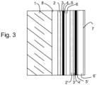
- FIG. 3 outside the invention, schematically presents a structure comprising two silver-based layers 4 and 4'.
- the usefulness of double layers of silver is well known from the prior art. At the cost of a higher cost due to the complexity introduced by the multiplicity of layers to be deposited, the presence of two layers of silver makes it possible on the one hand to further improve the emissivity of the glazing and to better control the neutrality of color in reflection.
- FIG. 3 shows with regard to the additional layers (2',3',4',5',6') as previously an assembly comprising layers (2' and 3') promoting the formation of a silver layer having an adequate structure to present in particular the best quality in terms of conduction and emissivity, one or more barrier layers (5') protecting the silver-based layer (4') against possible degradation during deposition of the layers which are superimposed on it, and one or more dielectric layers (6') to complete the filter.
- layer systems comprising or not oxide or oxy-nitride layers, TiOMx or TiOMxNy, were compared both for their emissivity and their neutrality in reflection .
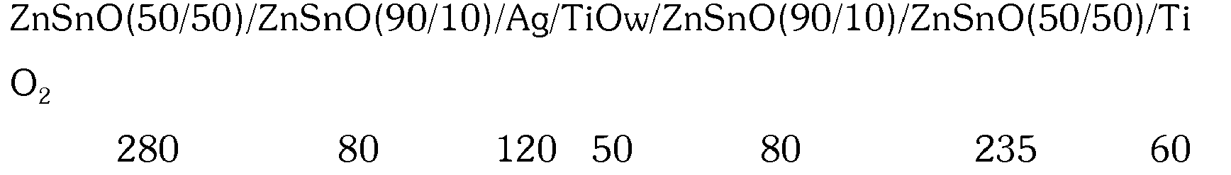
- the thicknesses of the layers are expressed in Angstrom for dielectrics and in mg/m 2 for silver.
- the deposits are carried out in an oxidizing atmosphere from metallic targets for the dielectrics, and in a neutral atmosphere (argon) for the silver layer and for the TiOw barrier layer.
- a set of similar layers is deposited by reducing the first layer ZnSnO(50/50) to 180 Angstrom, and by depositing on this layer in a weakly oxidizing atmosphere, from a ceramic target made of titanium oxide. , a layer of 100 Angstroms.
- the structure of this system is therefore:
- emissivity veil L* has* b* reference 0.040 4 42.62 - 0.65 - 8.08 with TiO 2 0.073 4 42.94 - 1.23 - 6.32
- emissivity veil L* has* b* TiZrYO (50%Zr) 0.038 1.5 40.18 2.6 - 4.3
- emissivity veil L* has* b* TiZrYO (25%Zr) 0.041 40.83 0.97 - 5.31
- this layer with a high refractive index does not significantly alter the quality of the emissivity when the glazing is subjected to heat treatment.
- Example 2 A test similar to that of Example 1 is carried out this time by depositing the layer based on titanium and zirconium (50%) in a nitrogen atmosphere.
- the deposit obtained under these conditions is an oxy-nitride, the oxygen of the target entering mainly into the composition of the layer.
- emissivity veil L* has* b* TiZrYON (50%Zr) 0.041 2 42.45 1.8 - 7.3
- the layer based on mixed oxide is also deposited in a nitrogen atmosphere.
- the ceramic target is made of a mixture of titanium and silicon (8% by weight).
- emissivity veil L* has* b* TiSiO (8%Si) 0.041 3.5 42.54 1.38 - 8.3
- the procedure is as in the previous examples, this time using a layer of mixed oxide of titanium and niobium of 100 ⁇ , the other layers being those presented above.
- the mixed oxide layer is deposited in weakly oxidizing environments from a ceramic target of titanium oxide and Nb 2 O 5 oxide comprising 30% in peas of Nb 2 O 5 .
- emissivity veil L* has* b* TiNbO 0.043 2.0 40.74 -0.45 - 3.41
- the mixed oxide layer of titanium and niobium like that of titanium and zirconium, is very stable under thermal testing.
- the silver layer retains good properties, and the coloring in reflection is very neutral.
- the first system is made up as follows, starting from glass:
- the second system has the same composition but the layer of mixed oxide of titanium and niobium is only 80 ⁇ thick instead of 100 ⁇
- TiNbO emissivity veil L* has* b* (has) 0.042 2.0 40.74 - 0.5 - 4.72 (b) 0.041 2.0 41.22 - 0.49 - 6.16
- the presence of the zinc oxide-based layer under the silver can be omitted without the heat treatment appreciably affecting the performance of the zinc oxide layer.
- silver or colorimetric characteristics in reflection can be omitted without the heat treatment appreciably affecting the performance of the zinc oxide layer.
Description
- La présente invention concerne les vitrages à faible émissivité autrement dit les vitrages qui réfléchissent une très large part des rayons infrarouges et laissent passer les rayons de longueur d'onde du visible. De manière plus précise l'invention concerne les vitrages à faible émissivité qui conservent ou améliorent leurs caractéristiques opto-énergétiques lorsqu'ils sont soumis à un traitement thermique intense tel qu'une trempe thermique et/ou une opération de bombage.
- Les vitrages à faible émissivité et à transmission lumineuse élevée sont traditionnellement obtenus en appliquant sur une feuille de verre une couche métallique mince, notamment une couche à base d'argent, laquelle est protégée contre les diverses altérations possibles par des couches protectrices de nature diélectrique.
- Les couches sont appliquées par une technique de dépôt sous vide du type dit « sputtering », le matériau des couches est obtenu à partir de cibles bombardées par des particules ionisées qui détachent les éléments de la cible lesquels, éventuellement après réaction avec les composants de l'atmosphère se déposent sur la feuille de verre constituant le substrat.
- La structure de base traditionnelle, lorsque l'ensemble comporte une seule couche d'argent est du type : verre/diélectrique 1/Ag/barrière/diélectrique II
- Dans ce type de structure la couche barrière est mise en œuvre essentiellement pour protéger la couche métallique d'argent d'une possible dégradation lors de l'application de la couche diélectrique II. C'est le cas en particulier lorsque cette dernière est déposée suivant une technique dite "réactive" dans laquelle le dépôt est réalisé à partir de cibles métalliques dans une atmosphère réagissant avec le métal déposé, notamment une atmosphère oxydante ou nitrurante.
- Les diélectriques I et II ont plusieurs fonctions. Ils sont nécessaires pour constituer un filtre interférentiel qui permet de réduire la réflexion des longueurs d'onde visible, et par conséquent permettent d'accroître la transmission lumineuse. Ils sont mis en œuvre aussi de façon que la fraction réfléchie dans le visible conduise à une neutralité de couleur aussi poussée que possible, et en particulier que la réflexion ne conduise pas à des nuances pourpres pour satisfaire aux préférences des clients à ce sujet. De surcroît le choix des couches diélectriques, ou systèmes de couches diélectriques, est tel que la neutralité en réflexion soit obtenue pour le plus large domaine d'angles d'incidence par rapport au vitrage.
- En dehors de ces fonctions proprement optiques, les couches diélectriques doivent dans toute la mesure du possible conduire à la formation d'une couche métallique dont les propriétés sont optimisées. Pour une même quantité de métal déposée, la couche peut en effet conduire à une émissivité plus ou moins élevée selon la façon dont elle se forme au contact des diélectriques et notamment du diélectrique I. Le brevet
US 5 110 662 , enseigne ainsi que l'usage d'une couche d'oxyde de zinc de faible épaisseur immédiatement sous la couche métallique permet d'améliorer sensiblement les propriétés de l'ensemble en particulier pour ce qui concerne l'émissivité. Cette amélioration semble provenir de la structure de cette couche de zinc qui présenterait une interface bien régulière avec la couche métallique déposée, favorisant la croissance de cette dernière dans une structure bien contrôlée. - Pour de multiples applications les vitrages avec les systèmes de couches, doivent pouvoir supporter un traitement thermique du type bombage/trempe. Dans ces traitements qui portent les vitrages à des températures qui peuvent atteindre et même dépasser 600°C pendant plusieurs minutes, les systèmes de couches peuvent se modifier. Suivant les conditions, ces modifications peuvent améliorer certaines propriétés, notamment l'émissivité, par ce qui semble être une transformation de la structure cristalline des couches à base d'argent. Mais ceci requiert le choix très particulier des ensembles de couches. A défaut, le plus généralement on observe une dégradation d'une ou plusieurs des propriétés fondamentalement recherchées pour ces vitrages, qu'il s'agisse par exemple de l'émissivité, de la coloration en réflexion ou encore de l'apparition d'un voile (« haze »).
- Les systèmes mis en œuvre sont le résultat de difficiles sélections, tant en ce qui concerne les matériaux des couches que celui de leur agencement dans ces empilages, la modification d'une caractéristique pour améliorer une propriété étant susceptible de se répercuter de manière négative sur d'autres propriétés.
- Par ailleurs, les exigences en matière de performances d'isolation sont toujours accrues. Si les vitrages, trempables ou non, présentant une émissivité de moins de 0,04 répondaient aux règlementations jusqu'à une époque récente, les règlementations les plus sévères nécessitent maintenant des vitrages dont l'émissivité ne dépasse pas 0,038, ou, selon les termes de ces réglementations, dans lequel le coefficient u, pour un vitrage isolant composé de deux feuilles de verre 4mm d'épaisseur, le système de couches étant en position 3 et l'espace entre les feuilles étant à 90% d'argon et 10% d'air sec, est tel que

- Pour atteindre ces performances thermiques, un moyen connu consiste à accroître l'épaisseur de la couche ou des couches d'argent. En procédant à cette modification, le système par ailleurs restant inchangé, il est connu que la neutralité de couleur en réflexion est perdue. Les vitrages modifiés offrent une réflexion de couleur pourpre.
- Pour rétablir une certaine neutralité dans le système interférentiel que constitue le système de couches, il est connu qu'il est alors nécessaire d'accroître simultanément le chemin optique correspondant aux couches situées sous l'argent. Cette manière de procéder n'est pas sans incidence sur d'autres propriétés, notamment lla transmission lumineuse ou la formation de voile.
- Pour obtenir le meilleur compromis entre une bonne transmission lumineuse et une bonne neutralité, il est également connu d'utiliser sous l'argent des couches à indice de réfraction élevées pour limiter l'augmentation d'épaisseur de ces couches diélectriques et les inconvénients qui en découlent.
- Parmi les couches répondant à cette condition l'oxyde de titane présente l'avantage, en plus d'un coût relativement bas, d'une bonne transmission lumineuse et d'une grande stabilité chimique. Pour cette raison l'utilisation de couches d'oxyde de titane peut sembler avantageuse. Cette utilisation l'est effectivement pour les vitrages qui ne sont pas soumis à un traitement thermique postérieur à la formation des couches. Pour ces vitrages, les systèmes comportent donc souvent une couche plus ou moins épaisse d'oxyde de titane. Par exemple,
WO 2006/097513 ,EP 1 538 131 ,EP 0 995 724 ,DE 10 2005 039 707 ouWO 00/72053 - A l'expérience les inventeurs ont constatés que l'introduction d'une couche de titane parmi celles situés sous la couche d'argent, conduisait à une dégradation des propriétés de cette couche après que le vitrage ait été soumis à un traitement thermique du type bombage/trempe. Cette dégradation est constatée alors même que la couche d'argent n'est pas même au contact de la couche de titane
- Bien que l'étude des mécanismes entrepris par les inventeurs ne soit pas achevée, il semble que cette altération soit liée un dérangement de la structure du système de couches initialement déposé. Le traitement thermique aurait pour conséquence une perturbation de l'interface de la couche d'argent avec les couches au contact desquels elle se trouve.
- Cette modification qui pourrait provenir de celle des couches contiguës, peut être aussi induite par contrecoup, par des couches qui ne sont pas au contact direct de l'argent. Le premier cas est celui par exemple dans lequel une couche sur laquelle repose l'argent présente une interface irrégulière comme celle provenant d'une structure colonnaire trop marquée. Une structure de ce type peut se trouve par exemple dans les couches d'oxyde de zinc d'épaisseur excessive, alors même qu'une couche de faible épaisseur, comme indiqué ci-dessus, est au contraire très favorable à la croissance d'une couche d'argent présentant de bonnes propriétés.
- Il apparaît, pour une raison qui n'est pas parfaitement analysée, que la présence d'une couche d'oxyde de titane qui présente nécessairement une certaine épaisseur pour jouer le rôle de couche anti-réfléchissante dans le système interférentiel, conduit à un réarrangement de la structure de ce système lorsqu'il est soumis à un traitement thermique du type bombage/trempe.
- Il est connu que l'oxyde de titane se présente sous des structures variées selon les conditions dans lesquelles la couche est formée. Dans les conditions qui influent sur la structure de cette couche, différents facteurs ont été identifiés. La nature de l'atmosphère dans laquelle le "sputtering" est effectué, notamment la concentration en oxygène de cette atmosphère intervient. La vitesse avec laquelle le dépôt est obtenu est un autre facteur reconnu antérieurement. Dans tous les cas les études sur la nature des couches montrent que l'oxyde de titane est soit amorphe soit sous forme rutile, soit sous forme anatase, soit encore, et c'est la très grande majorité des cas, sous forme d'un mélange de ces diverses formes.
- Il est encore connu que les conditions dans lesquelles les couches sont placées peuvent conduire à une modification progressive de leur structure. Les inventeurs ont constatés que les couches d'oxyde de titane soumises à des traitements thermiques subissent des modifications dans leur structure, modification qui semblent être la cause de l'altération des propriétés des couches situées directement ou nom au dessus d'elles.
- Un but de l'invention est donc, dans un système comprenant au moins une couche à base d'oxyde de titane, de proposer des moyens permettant de faire en sorte que la structure de cette couche reste sensiblement inchangée lorsqu'elle est soumise à un traitement thermique de type bombage/trempe.
- Un autre but de l'invention est de proposer des systèmes de couches comprenant une couche à base d'argent sous laquelle se trouve une couche à base d'oxyde ou d'oxy-nitrure de titane présentant cette propriété de sensiblement conserver sa structure même soumise à ces traitements.
- Un autre but de l'invention est de proposer des vitrages comportant un ensemble de couches dont une couche d'argent réfléchissant sélectivement les infrarouges, et des couches diélectriques déréfléchissantes situées au-dessus et au dessous de la couche d'argent, au moins une couche située sous l'argent étant une couche à base d'oxyde de titane présentant cette propriété de sensiblement conserver sa structure même soumise à ces traitements thermiques.
- Un but de l'invention est aussi de proposer des vitrages trempés et/ou bombés comprenant les systèmes de couches indiqués ci-dessus.
- Pour ce faire, l'invention a pour objet un vitrage revêtu selon la revendication 1.
- Les inventeurs ont montrés que ces buts pouvaient être atteints, au moins en partie, en constituant des couches à base d'oxyde ou d'oxy-nitrure de titane de type TiMOx ou TiMOxNy, dans lesquelles M est métal ou plusieurs métaux ou le silicium, ces métaux ou le silicium étant introduits en quantité tels, qu'ils modifient la structure de la couche pour la rendre pratiquement insensible aux traitements thermiques de type bombage/trempe.
- Les inventeurs partant de la constatation que les changements de structure cristalline consécutifs aux traitements thermiques considérés induisent des modifications, notamment à l'interface des couches, associent ces modifications à l'altération des propriétés des couches d'argent situées au-dessus de ces couches à base d'oxyde de titane.
- De façon avantageuse les inventeurs proposent aussi de choisir le ou les métaux ou le silicium entrant dans la composition de la couche à base d'oxyde ou d'oxy-nitrure de titane en fonction de leur contribution propre aux propriétés recherchées pour la couche en question. En particulier, selon l'invention il est avantageux d'utiliser des métaux dont les oxydes ou oxy-nitrures offrent simultanément une bonne transparence aux longueurs d'ondes du visible de même qu'un indice de réfraction relativement élevé.
- En dehors du silicium, parmi les métaux combinés au titane dans la couche à base d'oxyde de titane, on utilise avantageusement selon l'invention un ou plusieurs métaux du groupe comprenant : Zr, Ta, Nb,V, Nd, Ce, Hf, W, Mo, La, Y.
- Les métaux préférés étant ceux dont les oxydes ont les indices de réfraction les plus élevés, on utilise le plus volontiers Zr, Ta, Nb seuls ou en mélange et tout particulièrement Zr. Le choix des métaux additionnels est de préférence tel que les oxydes TiMOx ou oxy-nitrures TiMOxNy présentent un indice de réfraction supérieur à 2,2 et avantageusement supérieur à 2,3.
- Les métaux ou le silicium dans les couches à base d'oxyde ou d'oxy-nitrure de titane sont introduits avantageusement à partir de cibles métalliques ou de silicium, ou des cibles céramiques, correspondant aux compositions recherchées de telle sorte que le dépôt obtenu corresponde effectivement à un mélange intime des oxydes métalliques, ou de silicium, mélange qui s'oppose à la formation de structures cristallographiques régulières de dimensions significatives.
- Le dépôt, en particulier pour les oxydes, est effectué de préférence en atmosphère oxydante. Pour les cibles céramiques l'atmosphère peut être neutre, notamment d'argon, ou légèrement oxydante. Pour les cibles métalliques ou de silicium, l'atmosphère est oxydante.
- Les oxy-nitrures sont déposés en atmosphère comportant de l'azote. Comme il est connu le titane réagit plus facilement avec l'oxygène qu'avec l'azote. Pour obtenir la formation de ces oxy-nitrures la proportion d'azote dans l'atmosphère du dépôt doit être relativement importante. A titre indicatif si le dépôt est fait à partir de cathodes métalliques en atmosphère contenant simultanément de l'oxygène et de l'azote, le rapport N2/O2 sera avantageusement supérieur à 2 pour avoir une quantité d'azote significative dans l'oxy-nitrure. Cette proportion peut aller jusqu'à 3 ou 4 pour obtenir une teneur en azote dans l'oxy-nitrure qui soit supérieure à 10%.
- La présence d'azote dans l'oxy-nitrure de titane, comme celle du métal ou du silicium additionnel, tend à rendre moins aisée la transformation structurelle de l'oxyde de titane lors du traitement thermique. L'azote dans l'oxy-nitrure de titane peut conduire cependant à accroître le coefficient d'extinction de la couche, autrement dit à réduire un peu la transmission lumineuse, et à favoriser l'apparition d'un voile. Pour ces raisons la présence d'azote doit être bien contrôlée pour optimiser les propriétés.
- De façon générale, la présence d'azote dans l'oxy-nitrure de titane modifié, ne dépasse pas habituellement 30% dans le rapport N2/O2, et de préférence est inférieur à 25% et de façon particulièrement préférée est inférieur à 20%.
- Plus la teneur en métal ou silicium supplémentaire est élevée plus le « désordre » dans la structure de l'oxyde de titane est établi, et donc moins l'oxyde de titane est susceptible de constituer un réseau modifiable sous l'effet d'un traitement thermique de type bombage trempe. A l'inverse l'utilisation d'une forte proportion de métaux ou de silicium supplémentaires, tend à abaisser l'indice de réfraction de l'ensemble, l'oxyde de titane présentant l'indice le plus élevé.
- De manière à obtenir un effet stabilisant significatif la teneur en métal additionnel ou silicium est d'au moins 10% atomique par rapport au Ti dans le mélange. Il est de préférence supérieur à 15% et de manière particulièrement préférée supérieure à 20%.
- Pour conserver le plus possible les propriétés de l'oxyde de titane base de la couche, la proportion atomique en métal ou silicium additionnel est au plus de 60% et de préférence ne dépasse pas 50%.
- Pour une modification significative de ces chemins optiques, l'épaisseur de la couche TiMOx ou TiMOxNy est avantageusement au moins égale à 6nm, de préférence au moins égale à 8nm et de façon particulièrement préférée au moins égale à 10nm.
- En plus de la ou des couches TiMOx ou TiMOxNy mises en œuvre selon l'invention, pour favoriser la formation de la couche à base d'argent conduisant aux meilleures propriétés notamment de conduction électrique ou de basse émissivité, il est avantageux selon l'invention de disposer sous la couche à base d'argent, et en contact avec cette couche, une couche à base d'oxyde de zinc d'épaisseur limitée. La couche à base d'oxyde de zinc favorise la croissance de la couche à base d'argent pour autant que son épaisseur reste telle qu'elle ne se développe pas sous forme colonnaire.
- La couche à base d'oxyde de zinc peut comprendre des éléments « dopants » en faible quantité. Ces éléments sont notamment Al, Sn, ou Mg. Ils sont avantageusement en quantité atomique inférieure à 15% et de préférence inférieure à 10%.
- Une couche particulièrement préférée est constituée d'un oxyde de zinc comprenant entre 3 et 6% de Sn.
- L'épaisseur de la couche à base d'oxyde de zinc est avantageusement inférieure à 10nm, et de préférence inférieure à 8nm.
- Les couches à base d'argent sont avantageusement protégées de façon traditionnelle par une couche barrière ou sacrificielle. Le rôle de cette couche est principalement de prévenir la dégradation de la couche à base d'argent lors de la formation des couches diélectriques superposées à ces couches à base d'argent. Pour cela la couche barrière est formée d'un métal qui réagit dans les atmosphères susceptibles de dégrader l'argent.
- Les couches barrières les plus utilisées sont traditionnellement celles qui permettent ce type de protection et ne réduisent pas de façon significative les propriétés optiques de l'ensemble. On utilise des couches métalliques très peu épaisses pour ne pas réduire la transmission lumineuse. Ces couches sont en outre de préférence mises en œuvre dans des conditions telles que dans l'ensemble constitué elles soient transformées le plus possible en diélectriques transparents, la transformation intervenant en particulier au cours du dépôt réactif des couches situées au dessus de ces couches barrière.
- Des métaux et alliages préférés pour constituer ces couches barrière sont notamment : Ti, Zn, Sn, Zr, Cr, et NiCr. Les constituants préférés sont Ti et les alliages NiCr, et pour ces derniers les alliages constitués dans les proportions voisines de 80/20. Les barrières à base de titane sont préférées dans la mesure où elles offrent, une fois oxydées, une très faible absorption lumineuse. Les barrières à base de NiCr ont l'avantage de se prêter à un contrôle relativement précis de leur degré d'oxydation. Ces barrières au moins partiellement oxydées sont du type TiOw (avec w≤2) ou NiCrOv.
- En raison de leurs avantages respectifs, une combinaison de barrières de Ti et d'alliage NiCr est également particulièrement avantageuse. Le choix de préférence est alors de disposer la barrière NiCr au contact de la couche à base d'argent et de lui superposer une barrière Ti.
- Dans tous les cas la ou les barrières sont de préférence de très faible épaisseur. Ensemble elles restent avantageusement inférieures à 10nm et de préférence inférieures à 8nm. Séparément, chacune des couches barrière, présente une épaisseur qui n'est pas supérieure à 6nm.
- La composition de l'ensemble des couches formant filtre interférentiel, destiné notamment à la maîtrise de la transmission lumineuse et de la neutralité de couleur notamment en réflexion, comprend éventuellement des couches diélectriques supplémentaires situées sous la couche TiMOX ou TiMOxNy, ou au dessus de celle-ci, ou encore au dessus et en dessous.
- Parmi les couches diélectriques supplémentaires préférées figurent notamment au moins une couche d'oxyde de zinc ou d'un mélange d'oxyde de zinc et d'étain, d'aluminium ou de magnésium, dans des proportions atomiques Zn/Sn, Zn/Al, Zn/Mg comprises entre 30 et 70%.
- L'épaisseur de ces couches additionnelles est commandée notamment par celle de la couche TiMOx ou TiMOxNy, pour établir le chemin optique à une valeur satisfaisante pour constituer le filtre interférentiel correspondant à l'épaisseur de la couche d'argent choisie.
- Les assemblages de couches selon l'invention sont remarquables par la qualité de la couche d'argent qu'ils permettent d'obtenir après traitement thermique. Cette qualité se traduit pour une émissivité donnée par la quantité d'argent nécessaire pour atteindre cette émissivité. Plus petite est cette quantité meilleure est la couche d'argent.
- Pour des couches à base d'argent unique, la teneur pour les vitrages selon l'invention se situe entre 80 et 160mg/m2 , et de préférence entre 100 et 140mg/m2.
- Les vitrages selon l'invention sont tels qu'après un traitement thermique à une température qui n'est pas inférieure à 650°C pendant une durée d'au moins 3 minutes, la qualité de la couche d'argent est telle que le produit de la masse d'argent par unité de surface exprimée en mg/m2 par l'émissivité normale (Qxε) est inférieur à 5,0 de préférence inférieur à 4,8 et de façon particulièrement préférée inférieur à 4,6.
- L'invention est décrite de façon détaillée dans la suite, en faisant référence aux planches de dessins dans lesquelles :
- la
figure 1 représente un vitrage hors invention comprenant un ensemble de couches dont une couche réfléchissant les infrarouges ; - la
figure 2 présente un vitrage selon l'invention comportant un autre ensemble de couches dont une couche réfléchissant les infrarouges ; - la
figure 3 représente un vitrage hors invention comportant un ensemble de couches dont deux couches réfléchissant les infrarouges. - La
figure 1 représente en coupe schématique une feuille de verre 1 comportant un système de couches, lequel comprend une couche 4 réfléchissant les infrarouges à base d'argent. La couche à base d'argent peut le cas échéant être «dopée» d'un métal qui favorise sa structure cristalline ou sa durabilité. Un tel métal est par exemple de façon connue du palladium le platine, le nickel et le silicium. - De part et d'autres de l'argent des couches diélectriques forment le filtre interférentiel et protègent l'argent au cours de la constitution de l'ensemble et ultérieurement au cours de la vie du vitrage.
- Selon l'invention au moins une couche diélectrique 2 est constituée d'un oxyde mixte ou oxy-nitrure mixte de titane et d'un autre métal ou de silicium de type TiOx ou TiOxNy.
- La couche 4 située sous l'argent, lorsque l'ensemble est soumis à un traitement thermique vigoureux doit conserver sensiblement sa structure, contrairement au comportement d'une couche analogue traditionnelle à base de TiO2.
- Une couche 3 relativement mince à base d'oxyde de zinc et comprenant le cas échéant un métal dopant tel que Zn, Al ou Mg, est avantageusement disposée au contact direct de la couche à base d'argent. Cette couche favorise la croissance de la structure de la couche à base d'argent. Relativement mince en comparaison des couches diélectriques 2 ou 6 conférant l'essentiel des caractéristiques de filtre en combinaison avec la couche à base d'argent, cette couche 3 vis-à-vis de la couche à base d'argent ne masque pas la restructuration des couches sous-jacentes lorsque de tels changement s interviennent lors notamment d'un traitement thermique. Pour que la couche à base d'argent ne soit pas altérée, il est nécessaire suivant l'enseignement de l'invention que la couche 2 ne présente elle-même pas de modification significative de sa structure.
- Au dessus de l'argent traditionnellement figure une couche barrière 5 de faible épaisseur, qui prévient l'oxydation de l'argent lors du dépôt de couches déposées ultérieurement. Dans le cas représenté la couche diélectrique la plus externe est une couche épaisse 6, qui complète le filtre interférentiel.
- La structure représentée à la
figure 2 , est analogue à la précédente. Les couches semblables sont référencées comme à lafigure 1 . Cette structure comprend en plus des couches précédemment décrites, une couche superficielle 7, et un deuxième diélectrique 8 situé au contact de la feuille de verre 1. - La qualité principale des diélectriques 6 étant de contribuer à la constitution du filtre interférentiel, le choix de ces diélectriques est fonction de leurs propriétés optiques : indice, transparence etc. Ces diélectriques n'ont pas tous les qualités mécaniques qui garantissent une bonne résistance de l'ensemble des couches dans la mise en œuvre des vitrages. En particulier les couches ne sont pas toujours suffisamment résistantes aux rayures qui peuvent être occasionnées dans le stockage ou le transport.
- Pour cette raison il est connu de protéger l'ensemble des couches par le dépôt superficiel de couches très résistantes et qui contribuent très peu aux propriétés optiques. Des couches préférées sont par exemple d'oxyde de titane. L'épaisseur de ces couches est limitée à ce qui est utile pour conférer la résistance mécanique recherchée.
- La couche diélectrique 8 contribue à la formation des propriétés optiques de l'ensemble. Elle est généralement relativement épaisse. Cette couche intervient aussi pour protéger l'ensemble contre les migrations d'ions en provenance de la feuille de verre 1, migrations qui sont facilitées par le traitement thermique.
- Des couches traditionnelles pour cet usage sont notamment les couches d'oxydes mixtes de zinc et d'étain. Ces oxydes mixtes ont l'avantage d'être produits de manière relativement commode, et ajoutent à de bonnes propriétés optiques, une structure bien homogène sans formation colonnaires qui caractérisent par exemple les oxydes de zinc en couches épaisses.
- L'ordre des couches n'est pas nécessairement celui représenté à savoir une couche 8 épaisse et d'indice moindre que celui de la couche 2 à base de TiOMx ou TiOMxNy. L'ordre des couches peut être inversé la couche 2 étant par exemple au contact du verre et recouverte par la couche 8.
- Des couches supplémentaires peuvent encore figurer dans l'assemblage. Partant de la structure représentée à la
figure 2 il est possible par exemple d'ajouter une couche entre la couche 2 et la couche 3. Cette couche est par exemple de même nature que la couche 8, mais elle peut aussi être différente. - De la même manière la couche 6 peut être associée à une autre couche diélectrique située au dessus ou au dessous de la couche 6.
- La couche barrière 5 peut être simple ou composée elle-même de plusieurs couches. En particulier, comme indiqué précédemment il peut s'agir d'un ensemble comprenant une première couche d'oxyde de NiCr et d'une couche d'un oxyde titane.
- La
figure 3 , hors invention, présente de façon schématique une structure comportant deux couches à base d'argent 4 et 4'. L'utilité des doubles couches d'argent est bien connue de l'art antérieur. Au prix d'un coût supérieur du fait de la complexité introduite par la multiplicité des couches à déposer, la présence de deux couches d'argent permet d'une part d'améliore encore l'émissivité des vitrages et de mieux contrôler la neutralité de couleur en réflexion. - Toujours pour les mêmes raisons il est aussi possible de mettre en œuvre trois couches d'argent. Au-delà le bénéfice de couches d'argent supplémentaire est généralement peu significatif au regard de la complexité des systèmes correspondants.
- La
figure 3 , hors invention, montre à propos des couches additionnelles (2',3',4',5',6') comme précédemment un assemblage comportant des couches (2' et 3') favorisant la formation d'une couche d'argent présentant une structure adéquate pour présenter notamment la meilleure qualité en terme de conduction et d'émissivité, une ou des couches barrière (5') protégeant la couche à base d'argent (4') contre une possible dégradation au cours du dépôt des couches qui lui sont superposées, et une ou plusieurs couches diélectriques (6') pour compléter le filtre. - Comme précédemment à propos de la
figure 2 , l'ordre des couches à fonction essentiellement optique peut être changé de même que le nombre des couches mises en œuvre. - A titre d'exemple de mise en œuvre de l'invention des systèmes de couches comportant ou non les couches d'oxyde ou d'oxy-nitrure, TiOMx ou TiOMxNy, ont été comparés à la fois pour leur émissivité et leur neutralité en réflexion.
- Comme base de la comparaison le système suivant est utilisé en partant du verre :
- Les épaisseurs des couches sont exprimées en Angström pour les diélectriques et en mg/m2 pour l'argent.
- Les dépôts sont effectués en atmosphère oxydante à partir de cibles métalliques pour les diélectriques, et en atmosphère neutre (argon) pour la couche d'argent et pour la couche barrière TiOw.
- On procède au dépôt d'un ensemble de couches analogues en réduisant la première couche ZnSnO(50/50) à 180 Angström, et en déposant sur cette couche en atmosphère faiblement oxydante, à partir d'une cible céramique constituée d'oxyde de titane, une couche de 100Angströms. La structure de ce système est en conséquence :

- Les systèmes sont soumis à un traitement thermique à 650°C pendant trois minutes dans un four préchauffé et en atmosphère d'air. Les mesures d'émissivité normale, de voile (haze) et de colorimétrie en réflexion suivant le système CIE-LAB sont indiquées dans le tableau suivant :
émissivité voile L* a* b* référence 0,040 4 42,62 - 0,65 - 8,08 avec TiO2 0,073 4 42,94 - 1,23 - 6,32 - Ces résultats montrent que l'introduction de la couche TiO2 sous l'argent entraine une altération significative de l'émissivité de cette couche (et donc aussi de sa conduction électrique). Cette altération est attribuée à la modification de la nature cristallographique de la couche TiO2 lorsque celle-ci est soumise au traitement thermique.
- Suivant l'invention on procède de façon analogue en remplaçant la couche de 100 Angström de TiO2 par une couche de même épaisseur constituée d'un oxyde mixte de titane et de zirconium. Le dépôt de cette couche est effectué en atmosphère faiblement oxydante, à partir d'une cible céramique constituée en pourcentage pondéral de 50% de TiO, 46% de ZrO et 4% YO. La structure du système devient alors :

- Le résultat de l'épreuve est donné dans le tableau suivant :
émissivité voile L* a* b* TiZrYO (50%Zr) 0,038 1,5 40,18 2,6 - 4,3 - Contrairement à l'exemple précédent la qualité de l'argent (Qxε = 4,56) dans ces conditions n'est pas altérée par l'introduction de la couche à fort indice TiZrYO, et l'émissivité reste très faible en dépit d'un quantité d'argent relativement limitée.
- Un essai analogue est réalisé en remplaçant la cible utilisée pour le dépôt d'oxyde mixte de titane et de zirconium. Le taux de zirconium est ramené à 25% en poids, le taux de titane compensant cette baisse. Les résultats suivant les mêmes conditions d'épreuve sont reportés dans le tableau suivant :
émissivité voile L* a* b* TiZrYO (25%Zr) 0,041 40,83 0,97 - 5,31 - Avec la couche modifiée en proportions moindre que précédemment, on constate encore que cette couche à fort indice de réfraction n'altère sensiblement pas la qualité de l'émissivité lorsque le vitrage est soumis au traitement thermique.
- Un essai analogue à celui de l'exemple 1 est réalisé cette fois en déposant la couche à base de titane et de zirconium (50%) dans une atmosphère d'azote. En utilisant la cible céramique le dépôt obtenudans ces conditions est un oxy-nitrure, l'oxygène de la cible entrant majoritairement dans la composition de la couche.
- Le résultat de cet essai est le suivant :
émissivité voile L* a* b* TiZrYON (50%Zr) 0,041 2 42,45 1,8 - 7,3 - Comme précédemment on constate que l'introduction d'une couche d'oxy-nitrure mixte de Ti et Zr résiste bien à l'épreuve thermique. La qualité de la couche d'argent n'est pas sensiblement altérée.
- Dans cet essai la couche à base d'oxyde mixte est déposée également en atmosphère d'azote. La cible céramique est constituée d'un mélange de titane et de silicium (8% en poids).
- Les résultats figurent dan le tableau suivant :
émissivité voile L* a* b* TiSiO (8%Si) 0,041 3,5 42,54 1,38 - 8,3 - Il est procédé comme aux exemples précédents en utilisant cette fois une couche d'oxyde mixte de titane et de niobium de 100Å, les autres couches étant celles présentées ci-dessus. La couche d'oxyde mixte est déposée en milieux faiblement oxydant à partir d'une cible céramique d'oxyde de titane te d'oxyde Nb2O5 comprenant 30% en pois de Nb2O5.
- Les résultats figurent dan le tableau suivant :
émissivité voile L* a* b* TiNbO 0,043 2,0 40,74 -0,45 - 3,41 - La couche d'oxyde mixte de titane et de niobium, comme celle de titane et zirconium, est bien stable à l'épreuve thermique. La couche d'argent conserve de bonnes propriétés, et la coloration en réflexion est très neutre.
- Deux essais complémentaires sont effectués avec les mêmes oxydes mixtes de titane et de niobium, mais sans couche à base d'oxyde de zinc sous l'argent. Le premier système est constitué de la façon suivante en partant du verre :

- Le second système est de même composition mais la couche d'oxyde mixte de titane et niobium n'a que 80Å d'épaisseur au lieu de 100Å
- Les résultats figurent dan le tableau suivant :
TiNbO émissivité voile L* a* b* (a) 0,042 2,0 40,74 - 0,5 - 4,72 (b) 0,041 2,0 41,22 - 0,49 - 6,16 - Comme le montrent ces résultats, dans l'exemple considéré, la présence de la couche à base d'oxyde de zinc sous l'argent, peut être omise sans que le traitement thermique n'affecte de façon sensible les performances de la couche d'argent ou les caractéristiques colorimétriques en réflexion.
Claims (9)
- Vitrage revêtu d'un ensemble de couches minces par des techniques de dépôt sous vide ("sputtering") lui conférant des propriétés de réflexion des rayonnements infrarouges tout en conservant une transmission élevée dans le domaine visible,a. couches dont les propriétés notamment de réflexion dans l'infrarouge ne sont pas sensiblement altérées lorsque ce vitrage est soumis à un traitement thermique de type bombage/trempe, où après un traitement thermique à une température supérieure à 650°C et pendant une durée d'au moins 3 minutes la qualité de la couche à base d'argent est telle que Q x ε < 5,0 , Q étant exprimé en mg/m2, et ε étant l'émissivité normale, etb. comprenant une seule couche à base d'argent en une quantité comprise entre 80 et 160mg/m2 et des couches diélectriquesc. dont au moins une couche diélectrique sous-jacente par rapport à la couche à base d'argent est une couche à base d'oxyde ou d'oxy-nitrure de titane de type TiMOx ou TiMOxNy,i. dans laquelle M est un métal, ou plusieurs métaux du groupe comprenant Zr, Nb, Hf, Ta, Nd, V, Ce, W, Mo, La, Y, ou le silicium,ii. la proportion atomique du ou des métaux ou du silicium, M/Ti, n'étant pas inférieure à 10%, de préférence supérieure à 15% et de façon particulièrement préférée supérieure à 20%, et la proportion atomique du ou des métaux ou du silicium, M/Ti, étant au plus 60% pour prévenir une transformation significative de la structure cristallographique de la couche à base d'oxyde de titane précédemment déposée sous l'effet du traitement thermique, etiii. qui présente une épaisseur qui n'est pas inférieure à 6nm, etd. dans lequel sous la couche à base d'argent, et en contact avec celle-ci, se situe une couche à base d'oxyde de zinc, de type ZnO, ZnAlOz, ZnSnOz ou ZnMgOz, dans lesquelles la proportion atomique de Al/Zn, Sn/Zn ou Mg/Zn n'est pas supérieure à 15% et de préférence pas supérieure 10%, et d'épaisseur au plus égale à 10nm et de préférence au plus égale à 8nm,e. et comprenant un ensemble de couches :- verre/diélectrique/TiMOx ou TiMOxNy/ZnO ou ZnAIOz ou ZnSnOz ou ZnMgOz/Ag/barrière/ diélectrique II ou- verre/TiMOx ou TiMOxNy/diélectrique/ZnO ou ZnAIOz ou ZnSnOz ou ZnMgOz/Ag/barrière/ diélectrique II ou- verre/diélectrique/TiMOx ou TiMOxNy/diélectrique/ZnO ou ZnAIOz ou ZnSnOz ou ZnMgOz/Ag/barrière/ diélectrique II,f. les couches diélectriques additionnelles étant identiques ou différentes et dans lequel parmi la ou les couches diélectriques supplémentaire figure au moins une couche à base d'oxyde mixte de zinc et d'étain avec une proportion pondérale Zn/Sn comprise entre 30 et 70%.
- Vitrage selon la revendication précédente dans lequel dans la couche à base d'oxy-nitrure de titane la proportion N2/O2 n'est pas supérieure à 30% et de préférence pas supérieure à 25% , et de façon particulièrement préférée pas supérieure à 20%.
- Vitrage selon l'une des revendications précédentes dans lequel la couche à base d'oxyde ou d'oxy-nitrure de titane présente une épaisseur qui n'est pas inférieure à 8nm et de façon particulièrement préférée, pas inférieure à 10nm.
- Vitrage selon l'une des revendications précédentes dans lequel le ou les métaux ou le silicium entrant dans la composition de la couche à base d'oxyde ou d'oxy-nitrure de titane sont choisis de telle sorte et en proportions telles, que la couche en question présente un indice de réfraction supérieur à 2,2 et de préférence supérieur à 2,3.
- Vitrage selon l'une des revendications précédentes dans lequel la couche à base d'argent est couverte par au moins une couche barrière à base de titane TiOw avec w ≤ 2, ou une couche NiCrOv ou les deux.
- Vitrage selon la revendication 5 dans lequel la ou les couches TiOw et /ou NiCrOv, ensemble ont une épaisseur qui n'est pas supérieure à 10nm et de préférence pas supérieure à 8nm, chacune de ces couches individuellement ayant une épaisseur qui n'est pas supérieure à 6nm.
- Vitrage selon l'une des revendications précédentes comprenant une seule couche à base d'argent en une quantité comprise entre 100 et 140mg/m2.
- Vitrage selon la revendication 7 dans lequel après un traitement thermique à une température supérieure à 650°C et pendant une durée d'au moins 3 minutes la qualité de la couche à base d'argent est telle que


- Vitrage selon l'une des revendications précédentes comprenant un ensemble de couches :
verre/TiMOx ou TiMOxNy/ZnO ou ZnAIOz ou ZnSnOz ou ZnMgOz/Ag/barrière/ diélectrique II.
Priority Applications (2)
| Application Number | Priority Date | Filing Date | Title |
|---|---|---|---|
| PL08717902.4T PL2137116T5 (pl) | 2007-03-19 | 2008-03-17 | Oszklenie niskoemisyjne |
| EP08717902.4A EP2137116B2 (fr) | 2007-03-19 | 2008-03-17 | Vitrage à faible émissivité |
Applications Claiming Priority (3)
| Application Number | Priority Date | Filing Date | Title |
|---|---|---|---|
| EP07104429A EP1980539A1 (fr) | 2007-03-19 | 2007-03-19 | Vitrage à faible emissivite |
| EP08717902.4A EP2137116B2 (fr) | 2007-03-19 | 2008-03-17 | Vitrage à faible émissivité |
| PCT/EP2008/053166 WO2008113786A1 (fr) | 2007-03-19 | 2008-03-17 | Vitrage à faible émissivité |
Publications (3)
| Publication Number | Publication Date |
|---|---|
| EP2137116A1 EP2137116A1 (fr) | 2009-12-30 |
| EP2137116B1 EP2137116B1 (fr) | 2020-06-03 |
| EP2137116B2 true EP2137116B2 (fr) | 2023-10-11 |
Family
ID=38293960
Family Applications (2)
| Application Number | Title | Priority Date | Filing Date |
|---|---|---|---|
| EP07104429A Withdrawn EP1980539A1 (fr) | 2007-03-19 | 2007-03-19 | Vitrage à faible emissivite |
| EP08717902.4A Active EP2137116B2 (fr) | 2007-03-19 | 2008-03-17 | Vitrage à faible émissivité |
Family Applications Before (1)
| Application Number | Title | Priority Date | Filing Date |
|---|---|---|---|
| EP07104429A Withdrawn EP1980539A1 (fr) | 2007-03-19 | 2007-03-19 | Vitrage à faible emissivite |
Country Status (9)
| Country | Link |
|---|---|
| US (1) | US8105695B2 (fr) |
| EP (2) | EP1980539A1 (fr) |
| JP (1) | JP5553746B2 (fr) |
| CN (1) | CN101675011B (fr) |
| EA (1) | EA020682B1 (fr) |
| ES (1) | ES2814249T5 (fr) |
| HU (1) | HUE050289T2 (fr) |
| PL (1) | PL2137116T5 (fr) |
| WO (1) | WO2008113786A1 (fr) |
Families Citing this family (30)
| Publication number | Priority date | Publication date | Assignee | Title |
|---|---|---|---|---|
| WO2009080741A2 (fr) * | 2007-12-21 | 2009-07-02 | Agc Flat Glass Europe Sa | Réflecteur d'énergie solaire |
| KR20110033769A (ko) * | 2009-09-25 | 2011-03-31 | (주)엘지하우시스 | 저방사 유리 및 이의 제조방법 |
| EP2314553A1 (fr) * | 2009-10-16 | 2011-04-27 | AGC Glass Europe | Vitrage réflechissant émaille |
| FR2963788B1 (fr) * | 2010-08-10 | 2016-01-22 | Saint Gobain | Vitrage a proprietes antisolaires |
| TWI477635B (zh) * | 2010-09-15 | 2015-03-21 | Hon Hai Prec Ind Co Ltd | 殼體之製作方法及由該方法製得之殼體 |
| CN102603209A (zh) * | 2011-01-25 | 2012-07-25 | 鸿富锦精密工业(深圳)有限公司 | 镀膜玻璃及其制备方法 |
| GB201102724D0 (en) * | 2011-02-17 | 2011-03-30 | Pilkington Group Ltd | Heat treatable coated glass pane |
| US8557391B2 (en) | 2011-02-24 | 2013-10-15 | Guardian Industries Corp. | Coated article including low-emissivity coating, insulating glass unit including coated article, and/or methods of making the same |
| US8790783B2 (en) * | 2011-03-03 | 2014-07-29 | Guardian Industries Corp. | Barrier layers comprising Ni and/or Ti, coated articles including barrier layers, and methods of making the same |
| KR101381531B1 (ko) * | 2011-08-18 | 2014-04-07 | (주)엘지하우시스 | 열처리가 가능한 저방사 유리 및 이의 제조방법 |
| US9011969B2 (en) | 2011-12-27 | 2015-04-21 | Intermolecular, Inc. | Low-E panel with improved dielectric layer and method for forming the same |
| CN102515562A (zh) * | 2011-12-23 | 2012-06-27 | 福耀玻璃工业集团股份有限公司 | 一种镀膜产品 |
| US9279910B2 (en) * | 2013-03-13 | 2016-03-08 | Intermolecular, Inc. | Color shift of high LSG low emissivity coating after heat treatment |
| US9790127B2 (en) | 2013-03-14 | 2017-10-17 | Intermolecular, Inc. | Method to generate high LSG low-emissivity coating with same color after heat treatment |
| FR3030491B1 (fr) * | 2014-12-23 | 2016-12-30 | Saint Gobain | Vitrage comprenant un revetement protecteur |
| FR3032958B1 (fr) * | 2015-02-24 | 2017-02-17 | Saint Gobain | Vitrage comprenant un revetement protecteur. |
| RU2722384C2 (ru) * | 2015-09-08 | 2020-05-29 | Сэн-Гобэн Гласс Франс | Оконное стекло, содержащее функциональное покрытие |
| MX2019010435A (es) * | 2017-03-03 | 2019-11-05 | Guardian Glass Llc | Articulo recubierto que tiene un recubrimiento de baja emisividad con capa (s) reflectante (s) de infrarrojo (ir) y capa (s) dielectrica (s) de oxido de titanio dopado y niobio y metodo para fabricar el mismo. |
| US10196735B2 (en) * | 2017-03-03 | 2019-02-05 | Guardian Glass, LLC | Coated article having low-E coating with IR reflecting layer(s) and doped titanium oxide dielectric layer(s) and method of making same |
| US10138159B2 (en) * | 2017-03-09 | 2018-11-27 | Guardian Glass, LLC | Coated article having low-E coating with IR reflecting layer(s) and high index nitrided dielectric film having multiple layers |
| US10138158B2 (en) * | 2017-03-10 | 2018-11-27 | Guardian Glass, LLC | Coated article having low-E coating with IR reflecting layer(s) and high index nitrided dielectric layers |
| FR3065722B1 (fr) * | 2017-04-28 | 2021-09-24 | Saint Gobain | Vitrage colore et son procede d'obtention |
| US10336651B1 (en) | 2018-07-16 | 2019-07-02 | Guardian Glass, LLC | Coated article with IR reflecting layer(s) and silicon zirconium oxynitride layer(s) and method of making same |
| RU2696748C1 (ru) * | 2018-10-18 | 2019-08-05 | Общество с ограниченной ответственностью "Пилкингтон Гласс" | Изделие с гибридным сильнопоглощающим энергосберегающим покрытием на стеклянной подложке |
| FR3088636B1 (fr) * | 2018-11-16 | 2022-09-09 | Saint Gobain | Materiau traite thermiquement a proprietes mecaniques ameliorees |
| CN111393036A (zh) * | 2020-03-25 | 2020-07-10 | 四川猛犸半导体科技有限公司 | 一种薄膜器件 |
| WO2022053507A1 (fr) | 2020-09-10 | 2022-03-17 | Agc Glass Europe | Feuille de verre revêtue réfléchissant les uv pouvant être trempée |
| WO2023006543A1 (fr) | 2021-07-27 | 2023-02-02 | Agc Glass Europe | Vitrage pour empêcher les collisions d'oiseaux |
| GB202110849D0 (en) | 2021-07-28 | 2021-09-08 | Pilkington Group Ltd | Coated glass pane |
| FR3129938A1 (fr) * | 2021-12-08 | 2023-06-09 | Saint-Gobain Glass France | Vitrage comprenant un empilement antisolaire et un revêtement protecteur comprenant un oxyde d’yttrium et d’au moins un élément choisi parmi l’hafnium et/ou le titane |
Citations (4)
| Publication number | Priority date | Publication date | Assignee | Title |
|---|---|---|---|---|
| US5110637A (en) † | 1988-03-03 | 1992-05-05 | Asahi Glass Company Ltd. | Amorphous oxide film and article having such film thereon |
| US5962115A (en) † | 1995-06-08 | 1999-10-05 | Balzers Und Leybold Deutschland Holding Ag | Pane of transparent material having a low emissivity |
| WO2000072053A1 (fr) † | 1999-05-20 | 2000-11-30 | Saint-Gobain Glass France | Substrat transparent a revetement antireflets bas-emissif ou anti-solaire |
| WO2006048463A1 (fr) † | 2004-11-08 | 2006-05-11 | Glaverbel | Vitrage |
Family Cites Families (13)
| Publication number | Priority date | Publication date | Assignee | Title |
|---|---|---|---|---|
| US5059295A (en) * | 1986-12-29 | 1991-10-22 | Ppg Industries, Inc. | Method of making low emissivity window |
| DE3853970D1 (de) | 1987-07-22 | 1995-07-20 | Philips Patentverwaltung | Optisches Interferenzfilter. |
| EP0963960A1 (fr) | 1998-06-08 | 1999-12-15 | Glaverbel | Substrat transparent revêtu d'une couche d'argent |
| FR2784985B1 (fr) | 1998-10-22 | 2001-09-21 | Saint Gobain Vitrage | Substrat transparent muni d'un empilement de couches minces |
| US20020136905A1 (en) * | 1999-11-24 | 2002-09-26 | Medwick Paul A. | Low shading coefficient and low emissivity coatings and coated articles |
| DE60336634D1 (de) * | 2002-02-11 | 2011-05-19 | Ppg Ind Ohio Inc | Sonnenschutzbeschichtung |
| CA2477845C (fr) * | 2002-03-01 | 2010-10-12 | Cardinal Cg Company | Revetement a couches minces presentant une couche de base transparente |
| EP1375445A1 (fr) | 2002-06-17 | 2004-01-02 | Glaverbel | Procédé de fabrication d'un vitrage pourvu d'un revêtement multicouche |
| JP4114429B2 (ja) * | 2002-07-31 | 2008-07-09 | 旭硝子株式会社 | 積層体および構造体 |
| EP1611265B1 (fr) | 2003-03-28 | 2017-05-03 | Vitro, S.A.B. de C.V. | Substrats recouverts de melanges de materiaux en titane et en aluminium |
| DE50312424D1 (de) * | 2003-12-02 | 2010-04-01 | Scheuten Glasgroep Bv | Temperbares Low-e-Schichtsystem; Verfahren zur Herstellung und Low-e-Glasprodukt mit Schichtsystem |
| BE1016553A3 (fr) * | 2005-03-17 | 2007-01-09 | Glaverbel | Vitrage a faible emissivite. |
| DE102005039707B4 (de) * | 2005-08-23 | 2009-12-03 | Saint-Gobain Glass Deutschland Gmbh | Thermisch hoch belastbares Low-E-Schichtsystem für transparente Substrate, insbesondere für Glasscheiben |
-
2007
- 2007-03-19 EP EP07104429A patent/EP1980539A1/fr not_active Withdrawn
-
2008
- 2008-03-17 PL PL08717902.4T patent/PL2137116T5/pl unknown
- 2008-03-17 EP EP08717902.4A patent/EP2137116B2/fr active Active
- 2008-03-17 CN CN200880014802.0A patent/CN101675011B/zh not_active Expired - Fee Related
- 2008-03-17 JP JP2010500200A patent/JP5553746B2/ja active Active
- 2008-03-17 HU HUE08717902A patent/HUE050289T2/hu unknown
- 2008-03-17 EA EA200901252A patent/EA020682B1/ru not_active IP Right Cessation
- 2008-03-17 ES ES08717902T patent/ES2814249T5/es active Active
- 2008-03-17 WO PCT/EP2008/053166 patent/WO2008113786A1/fr active Application Filing
- 2008-03-17 US US12/532,318 patent/US8105695B2/en active Active
Patent Citations (4)
| Publication number | Priority date | Publication date | Assignee | Title |
|---|---|---|---|---|
| US5110637A (en) † | 1988-03-03 | 1992-05-05 | Asahi Glass Company Ltd. | Amorphous oxide film and article having such film thereon |
| US5962115A (en) † | 1995-06-08 | 1999-10-05 | Balzers Und Leybold Deutschland Holding Ag | Pane of transparent material having a low emissivity |
| WO2000072053A1 (fr) † | 1999-05-20 | 2000-11-30 | Saint-Gobain Glass France | Substrat transparent a revetement antireflets bas-emissif ou anti-solaire |
| WO2006048463A1 (fr) † | 2004-11-08 | 2006-05-11 | Glaverbel | Vitrage |
Also Published As
| Publication number | Publication date |
|---|---|
| ES2814249T5 (es) | 2024-04-22 |
| JP2010521410A (ja) | 2010-06-24 |
| ES2814249T3 (es) | 2021-03-26 |
| US8105695B2 (en) | 2012-01-31 |
| CN101675011B (zh) | 2016-02-03 |
| WO2008113786A1 (fr) | 2008-09-25 |
| EP1980539A1 (fr) | 2008-10-15 |
| PL2137116T3 (pl) | 2020-11-16 |
| CN101675011A (zh) | 2010-03-17 |
| US20100167034A1 (en) | 2010-07-01 |
| EA020682B1 (ru) | 2015-01-30 |
| EA200901252A1 (ru) | 2010-04-30 |
| EP2137116A1 (fr) | 2009-12-30 |
| PL2137116T5 (pl) | 2024-01-29 |
| JP5553746B2 (ja) | 2014-07-16 |
| HUE050289T2 (hu) | 2020-11-30 |
| EP2137116B1 (fr) | 2020-06-03 |
Similar Documents
| Publication | Publication Date | Title |
|---|---|---|
| EP2137116B2 (fr) | Vitrage à faible émissivité | |
| EP2262745B2 (fr) | Vitrage revetu de couches minces | |
| EP3702337B1 (fr) | Vitrage revêtu de couches minces | |
| EP2262743B2 (fr) | Vitrage revêtu de couches minces | |
| EP2956421B1 (fr) | Vitrage de contrôle solaire | |
| EP2331475B1 (fr) | Vitrage à réflexion élevée | |
| EP2027076B1 (fr) | Vitrage a faible emissivite | |
| EP2686279B1 (fr) | Vitrage isolant | |
| EP3172175B1 (fr) | Panneau de verre décoratif | |
| EP1663895A1 (fr) | Substrat transparent revetu d un empilement de couches mince s a proprietes de reflexion dans l infrarouge et/ou dans le domaine du rayonnement solaire | |
| EP2585411B1 (fr) | Vitrage isolant | |
| FR2948037A1 (fr) | Materiau photocatalytique | |
| EP2585410B1 (fr) | Vitrage isolant | |
| WO2011110584A1 (fr) | Vitrage a reflexion elevee | |
| EP2314553A1 (fr) | Vitrage réflechissant émaille | |
| EP3347322B1 (fr) | Vitrage comprenant un empilement de couches minces | |
| EP2822908B1 (fr) | Vitrage isolant | |
| EP2545011B1 (fr) | Vitrage a reflexion elevee | |
| EP3419946B1 (fr) | Vitrage de contrôle solaire comprenant une couche d'un alliage nicucr |
Legal Events
| Date | Code | Title | Description |
|---|---|---|---|
| PUAI | Public reference made under article 153(3) epc to a published international application that has entered the european phase |
Free format text: ORIGINAL CODE: 0009012 |
|
| 17P | Request for examination filed |
Effective date: 20090918 |
|
| AK | Designated contracting states |
Kind code of ref document: A1 Designated state(s): AT BE BG CH CY CZ DE DK EE ES FI FR GB GR HR HU IE IS IT LI LT LU LV MC MT NL NO PL PT RO SE SI SK TR |
|
| 17Q | First examination report despatched |
Effective date: 20100107 |
|
| TPAC | Observations filed by third parties |
Free format text: ORIGINAL CODE: EPIDOSNTIPA |
|
| DAX | Request for extension of the european patent (deleted) | ||
| RAP1 | Party data changed (applicant data changed or rights of an application transferred) |
Owner name: AGC GLASS EUROPE |
|
| RAP1 | Party data changed (applicant data changed or rights of an application transferred) |
Owner name: AGC GLASS EUROPE |
|
| STAA | Information on the status of an ep patent application or granted ep patent |
Free format text: STATUS: EXAMINATION IS IN PROGRESS |
|
| GRAP | Despatch of communication of intention to grant a patent |
Free format text: ORIGINAL CODE: EPIDOSNIGR1 |
|
| STAA | Information on the status of an ep patent application or granted ep patent |
Free format text: STATUS: GRANT OF PATENT IS INTENDED |
|
| INTG | Intention to grant announced |
Effective date: 20200107 |
|
| GRAS | Grant fee paid |
Free format text: ORIGINAL CODE: EPIDOSNIGR3 |
|
| GRAA | (expected) grant |
Free format text: ORIGINAL CODE: 0009210 |
|
| STAA | Information on the status of an ep patent application or granted ep patent |
Free format text: STATUS: THE PATENT HAS BEEN GRANTED |
|
| AK | Designated contracting states |
Kind code of ref document: B1 Designated state(s): AT BE BG CH CY CZ DE DK EE ES FI FR GB GR HR HU IE IS IT LI LT LU LV MC MT NL NO PL PT RO SE SI SK TR |
|
| REG | Reference to a national code |
Ref country code: GB Ref legal event code: FG4D Free format text: NOT ENGLISH |
|
| REG | Reference to a national code |
Ref country code: CH Ref legal event code: EP Ref country code: AT Ref legal event code: REF Ref document number: 1276853 Country of ref document: AT Kind code of ref document: T Effective date: 20200615 |
|
| REG | Reference to a national code |
Ref country code: DE Ref legal event code: R096 Ref document number: 602008062804 Country of ref document: DE |
|
| REG | Reference to a national code |
Ref country code: RO Ref legal event code: EPE |
|
| REG | Reference to a national code |
Ref country code: LT Ref legal event code: MG4D |
|
| PG25 | Lapsed in a contracting state [announced via postgrant information from national office to epo] |
Ref country code: FI Free format text: LAPSE BECAUSE OF FAILURE TO SUBMIT A TRANSLATION OF THE DESCRIPTION OR TO PAY THE FEE WITHIN THE PRESCRIBED TIME-LIMIT Effective date: 20200603 Ref country code: GR Free format text: LAPSE BECAUSE OF FAILURE TO SUBMIT A TRANSLATION OF THE DESCRIPTION OR TO PAY THE FEE WITHIN THE PRESCRIBED TIME-LIMIT Effective date: 20200904 Ref country code: NO Free format text: LAPSE BECAUSE OF FAILURE TO SUBMIT A TRANSLATION OF THE DESCRIPTION OR TO PAY THE FEE WITHIN THE PRESCRIBED TIME-LIMIT Effective date: 20200903 Ref country code: SE Free format text: LAPSE BECAUSE OF FAILURE TO SUBMIT A TRANSLATION OF THE DESCRIPTION OR TO PAY THE FEE WITHIN THE PRESCRIBED TIME-LIMIT Effective date: 20200603 Ref country code: LT Free format text: LAPSE BECAUSE OF FAILURE TO SUBMIT A TRANSLATION OF THE DESCRIPTION OR TO PAY THE FEE WITHIN THE PRESCRIBED TIME-LIMIT Effective date: 20200603 |
|
| REG | Reference to a national code |
Ref country code: NL Ref legal event code: MP Effective date: 20200603 |
|
| PG25 | Lapsed in a contracting state [announced via postgrant information from national office to epo] |
Ref country code: LV Free format text: LAPSE BECAUSE OF FAILURE TO SUBMIT A TRANSLATION OF THE DESCRIPTION OR TO PAY THE FEE WITHIN THE PRESCRIBED TIME-LIMIT Effective date: 20200603 Ref country code: HR Free format text: LAPSE BECAUSE OF FAILURE TO SUBMIT A TRANSLATION OF THE DESCRIPTION OR TO PAY THE FEE WITHIN THE PRESCRIBED TIME-LIMIT Effective date: 20200603 |
|
| REG | Reference to a national code |
Ref country code: HU Ref legal event code: AG4A Ref document number: E050289 Country of ref document: HU |
|
| REG | Reference to a national code |
Ref country code: AT Ref legal event code: MK05 Ref document number: 1276853 Country of ref document: AT Kind code of ref document: T Effective date: 20200603 |
|
| PG25 | Lapsed in a contracting state [announced via postgrant information from national office to epo] |
Ref country code: NL Free format text: LAPSE BECAUSE OF FAILURE TO SUBMIT A TRANSLATION OF THE DESCRIPTION OR TO PAY THE FEE WITHIN THE PRESCRIBED TIME-LIMIT Effective date: 20200603 |
|
| PG25 | Lapsed in a contracting state [announced via postgrant information from national office to epo] |
Ref country code: EE Free format text: LAPSE BECAUSE OF FAILURE TO SUBMIT A TRANSLATION OF THE DESCRIPTION OR TO PAY THE FEE WITHIN THE PRESCRIBED TIME-LIMIT Effective date: 20200603 Ref country code: AT Free format text: LAPSE BECAUSE OF FAILURE TO SUBMIT A TRANSLATION OF THE DESCRIPTION OR TO PAY THE FEE WITHIN THE PRESCRIBED TIME-LIMIT Effective date: 20200603 Ref country code: PT Free format text: LAPSE BECAUSE OF FAILURE TO SUBMIT A TRANSLATION OF THE DESCRIPTION OR TO PAY THE FEE WITHIN THE PRESCRIBED TIME-LIMIT Effective date: 20201006 |
|
| PG25 | Lapsed in a contracting state [announced via postgrant information from national office to epo] |
Ref country code: SK Free format text: LAPSE BECAUSE OF FAILURE TO SUBMIT A TRANSLATION OF THE DESCRIPTION OR TO PAY THE FEE WITHIN THE PRESCRIBED TIME-LIMIT Effective date: 20200603 Ref country code: IS Free format text: LAPSE BECAUSE OF FAILURE TO SUBMIT A TRANSLATION OF THE DESCRIPTION OR TO PAY THE FEE WITHIN THE PRESCRIBED TIME-LIMIT Effective date: 20201003 |
|
| REG | Reference to a national code |
Ref country code: DE Ref legal event code: R026 Ref document number: 602008062804 Country of ref document: DE |
|
| PLBI | Opposition filed |
Free format text: ORIGINAL CODE: 0009260 |
|
| PLAB | Opposition data, opponent's data or that of the opponent's representative modified |
Free format text: ORIGINAL CODE: 0009299OPPO |
|
| PLAX | Notice of opposition and request to file observation + time limit sent |
Free format text: ORIGINAL CODE: EPIDOSNOBS2 |
|
| REG | Reference to a national code |
Ref country code: ES Ref legal event code: FG2A Ref document number: 2814249 Country of ref document: ES Kind code of ref document: T3 Effective date: 20210326 |
|
| 26 | Opposition filed |
Opponent name: PILKINGTON GROUP LIMITED Effective date: 20210303 |
|
| R26 | Opposition filed (corrected) |
Opponent name: PILKINGTON GROUP LIMITED Effective date: 20210303 |
|
| PG25 | Lapsed in a contracting state [announced via postgrant information from national office to epo] |
Ref country code: DK Free format text: LAPSE BECAUSE OF FAILURE TO SUBMIT A TRANSLATION OF THE DESCRIPTION OR TO PAY THE FEE WITHIN THE PRESCRIBED TIME-LIMIT Effective date: 20200603 |
|
| PG25 | Lapsed in a contracting state [announced via postgrant information from national office to epo] |
Ref country code: SI Free format text: LAPSE BECAUSE OF FAILURE TO SUBMIT A TRANSLATION OF THE DESCRIPTION OR TO PAY THE FEE WITHIN THE PRESCRIBED TIME-LIMIT Effective date: 20200603 |
|
| PLBB | Reply of patent proprietor to notice(s) of opposition received |
Free format text: ORIGINAL CODE: EPIDOSNOBS3 |
|
| PG25 | Lapsed in a contracting state [announced via postgrant information from national office to epo] |
Ref country code: MC Free format text: LAPSE BECAUSE OF FAILURE TO SUBMIT A TRANSLATION OF THE DESCRIPTION OR TO PAY THE FEE WITHIN THE PRESCRIBED TIME-LIMIT Effective date: 20200603 |
|
| REG | Reference to a national code |
Ref country code: CH Ref legal event code: PL |
|
| PG25 | Lapsed in a contracting state [announced via postgrant information from national office to epo] |
Ref country code: IE Free format text: LAPSE BECAUSE OF NON-PAYMENT OF DUE FEES Effective date: 20210317 Ref country code: LI Free format text: LAPSE BECAUSE OF NON-PAYMENT OF DUE FEES Effective date: 20210331 Ref country code: CH Free format text: LAPSE BECAUSE OF NON-PAYMENT OF DUE FEES Effective date: 20210331 |
|
| APAH | Appeal reference modified |
Free format text: ORIGINAL CODE: EPIDOSCREFNO |
|
| APBM | Appeal reference recorded |
Free format text: ORIGINAL CODE: EPIDOSNREFNO |
|
| APBP | Date of receipt of notice of appeal recorded |
Free format text: ORIGINAL CODE: EPIDOSNNOA2O |
|
| PGFP | Annual fee paid to national office [announced via postgrant information from national office to epo] |
Ref country code: RO Payment date: 20230227 Year of fee payment: 16 Ref country code: LU Payment date: 20230227 Year of fee payment: 16 Ref country code: FR Payment date: 20230208 Year of fee payment: 16 Ref country code: CZ Payment date: 20230228 Year of fee payment: 16 Ref country code: BG Payment date: 20230215 Year of fee payment: 16 |
|
| PG25 | Lapsed in a contracting state [announced via postgrant information from national office to epo] |
Ref country code: CY Free format text: LAPSE BECAUSE OF FAILURE TO SUBMIT A TRANSLATION OF THE DESCRIPTION OR TO PAY THE FEE WITHIN THE PRESCRIBED TIME-LIMIT Effective date: 20200603 |
|
| PGFP | Annual fee paid to national office [announced via postgrant information from national office to epo] |
Ref country code: TR Payment date: 20230316 Year of fee payment: 16 Ref country code: IT Payment date: 20230213 Year of fee payment: 16 Ref country code: HU Payment date: 20230213 Year of fee payment: 16 Ref country code: GB Payment date: 20230202 Year of fee payment: 16 Ref country code: DE Payment date: 20230131 Year of fee payment: 16 Ref country code: BE Payment date: 20230216 Year of fee payment: 16 |
|
| APBU | Appeal procedure closed |
Free format text: ORIGINAL CODE: EPIDOSNNOA9O |
|
| P01 | Opt-out of the competence of the unified patent court (upc) registered |
Effective date: 20230620 |
|
| PGFP | Annual fee paid to national office [announced via postgrant information from national office to epo] |
Ref country code: ES Payment date: 20230407 Year of fee payment: 16 |
|
| PGFP | Annual fee paid to national office [announced via postgrant information from national office to epo] |
Ref country code: PL Payment date: 20230215 Year of fee payment: 16 |
|
| PUAH | Patent maintained in amended form |
Free format text: ORIGINAL CODE: 0009272 |
|
| STAA | Information on the status of an ep patent application or granted ep patent |
Free format text: STATUS: PATENT MAINTAINED AS AMENDED |
|
| 27A | Patent maintained in amended form |
Effective date: 20231011 |
|
| AK | Designated contracting states |
Kind code of ref document: B2 Designated state(s): AT BE BG CH CY CZ DE DK EE ES FI FR GB GR HR HU IE IS IT LI LT LU LV MC MT NL NO PL PT RO SE SI SK TR |
|
| REG | Reference to a national code |
Ref country code: DE Ref legal event code: R102 Ref document number: 602008062804 Country of ref document: DE |