EP2135151B1 - Electronic device locking system - Google Patents
Electronic device locking system Download PDFInfo
- Publication number
- EP2135151B1 EP2135151B1 EP08725868.7A EP08725868A EP2135151B1 EP 2135151 B1 EP2135151 B1 EP 2135151B1 EP 08725868 A EP08725868 A EP 08725868A EP 2135151 B1 EP2135151 B1 EP 2135151B1
- Authority
- EP
- European Patent Office
- Prior art keywords
- display member
- post
- cap
- latch
- base
- Prior art date
- Legal status (The legal status is an assumption and is not a legal conclusion. Google has not performed a legal analysis and makes no representation as to the accuracy of the status listed.)
- Not-in-force
Links
Images


Classifications
-
- G—PHYSICS
- G06—COMPUTING OR CALCULATING; COUNTING
- G06F—ELECTRIC DIGITAL DATA PROCESSING
- G06F1/00—Details not covered by groups G06F3/00 - G06F13/00 and G06F21/00
- G06F1/16—Constructional details or arrangements
- G06F1/1613—Constructional details or arrangements for portable computers
- G06F1/1633—Constructional details or arrangements of portable computers not specific to the type of enclosures covered by groups G06F1/1615 - G06F1/1626
- G06F1/1675—Miscellaneous details related to the relative movement between the different enclosures or enclosure parts
- G06F1/1679—Miscellaneous details related to the relative movement between the different enclosures or enclosure parts for locking or maintaining the movable parts of the enclosure in a fixed position, e.g. latching mechanism at the edge of the display in a laptop or for the screen protective cover of a PDA
-
- E—FIXED CONSTRUCTIONS
- E05—LOCKS; KEYS; WINDOW OR DOOR FITTINGS; SAFES
- E05B—LOCKS; ACCESSORIES THEREFOR; HANDCUFFS
- E05B17/00—Accessories in connection with locks
- E05B17/0025—Devices for forcing the wing firmly against its seat or to initiate the opening of the wing
- E05B17/0033—Devices for forcing the wing firmly against its seat or to initiate the opening of the wing for opening only
- E05B17/0037—Spring-operated
-
- E—FIXED CONSTRUCTIONS
- E05—LOCKS; KEYS; WINDOW OR DOOR FITTINGS; SAFES
- E05B—LOCKS; ACCESSORIES THEREFOR; HANDCUFFS
- E05B65/00—Locks or fastenings for special use
- E05B65/006—Locks or fastenings for special use for covers or panels
- E05B65/0067—Locks or fastenings for special use for covers or panels for portable computers, e.g. for locking the screen panel to the keyboard panel
-
- E—FIXED CONSTRUCTIONS
- E05—LOCKS; KEYS; WINDOW OR DOOR FITTINGS; SAFES
- E05C—BOLTS OR FASTENING DEVICES FOR WINGS, SPECIALLY FOR DOORS OR WINDOWS
- E05C9/00—Arrangements of simultaneously actuated bolts or other securing devices at well-separated positions on the same wing
- E05C9/04—Arrangements of simultaneously actuated bolts or other securing devices at well-separated positions on the same wing with two sliding bars moved in opposite directions when fastening or unfastening
- E05C9/045—Arrangements of simultaneously actuated bolts or other securing devices at well-separated positions on the same wing with two sliding bars moved in opposite directions when fastening or unfastening with inclined surfaces, e.g. spiral or helicoidal
-
- G—PHYSICS
- G06—COMPUTING OR CALCULATING; COUNTING
- G06F—ELECTRIC DIGITAL DATA PROCESSING
- G06F1/00—Details not covered by groups G06F3/00 - G06F13/00 and G06F21/00
- G06F1/16—Constructional details or arrangements
- G06F1/1613—Constructional details or arrangements for portable computers
- G06F1/1615—Constructional details or arrangements for portable computers with several enclosures having relative motions, each enclosure supporting at least one I/O or computing function
- G06F1/1616—Constructional details or arrangements for portable computers with several enclosures having relative motions, each enclosure supporting at least one I/O or computing function with folding flat displays, e.g. laptop computers or notebooks having a clamshell configuration, with body parts pivoting to an open position around an axis parallel to the plane they define in closed position
Definitions
- Electronic devices such as laptop or notebook computers, generally comprise hook-style latch designs operable to engage a locking mechanism to secure a rotatable display member to a base member (e.g., in a closed position or tablet position).
- Such latch designs are susceptible to catching and/or otherwise becoming entangled with foreign objects, such as for example, clothing or jewelry, thereby increasing the likelihood of damage to the latch and/or the electronic device.
- hook-style latch designs consume excessive space within the electronic devices.
- US 2006/133019 A1 discloses a latch assembly comprising a plurality of latches configured to engage with a plurality of latch sockets appropriately situated at corners of an electronic device.
- a release mechanism is adapted to secure and subsequently release the plurality of latches from the plurality of latch sockets.
- the release mechanism includes a spring-biased release button, and a plurality of links rotationally coupled to the release button.
- the first link is adapted to prevent vertical movement of the first latch when the first link is placed in a first position caused when the cover is placed in a closed position. When the release button is depressed, the first link is placed into a second position to allow the cover to be opened.
- US 2006/279919 A1 discloses a case structure of an electronic device, which comprises a first shell, a second shell, a first engagement element, a second engagement element, a first spring element, a second spring element and a plug element.
- the first engagement element protrudes from the first shell.
- the second shell having a first penetrating opening allows the first engagement element to pass through.
- the second engagement element having a button portion passes through a second penetrating opening of the second shell.
- the second engagement element is driven by the button portion and the first spring element to control the second engagement element and the first engagement element to engage or disengage from each other.
- the plug element located in the second shell is pushed for filling in the first penetrating opening by the second spring element.
- FIGURES 1A-3C like numerals being used for like and corresponding parts of the various drawings.
- FIGURE 1A is a diagram of an embodiment of an electronic device 10 in which a locking system 12 is employed to advantage.
- electronic device 10 comprises a laptop or notebook computer 14; however, it should be understood that electronic device 10 may comprise any type of electronic device such as, but not limited to, a convertible tablet personal computer, a personal digital assistant, or any other type of portable or non-portable computing device having a locking system 12 to secure portions thereof.
- electronic device 10 comprises a display member 16 rotatably coupled to a base member 18.
- Display member 16 may be coupled to base member 18 by a hinge or other element to enable variable positioning of display member 16 relative to base member 18.
- Display member 16 comprises a display screen 19 supported by a housing 20 formed from a top wall 22, a bottom wall 24, a rear wall 26, a front wall/bezel 28 and a pair of sidewalls 30 and 32.
- Base member 18 comprises a housing 34 formed by a top wall defining a working surface 36, a bottom wall 38, a front wall 40, a rear wall 42 and a pair of sidewalls 44 and 46.
- locking system 12 comprises a pair of pins or posts 48 and 50 extending outwardly from display member 16 and insertible into corresponding openings 52 and 54, respectively, on working surface 36 to secure display member 16 to base member 18 (e.g., positioned such that display member 16 is adjacent to and otherwise covers working surface 36 of base member 18 such as in a closed position where display screen 19 is disposed adjacent to working surface 36 or in a tablet position where display screen 19 remains exposed for use as a tablet personal computer).
- openings 52 and 54 are concealed or otherwise enclosed by caps 56a and 56b, respectively.
- caps 56a and 56b are mounted flush (i.e., flush or substantially flush) with working surface 36 and enclose openings 52 and 54, respectively, to prevent debris or other unwanted matter from entering housing 34; however, it should be understood that openings 52 and 54 may be configured without caps 56a and 56b.
- caps 56a and 56b are retracted and/or otherwise removed from covering openings 42 and 54 in response to insertion of posts 48 and 50 within openings 52 and 54, respectively.
- posts 48 and 50 extend outward from bezel 28 and comprise generally circular cross-sectional areas which may vary in dimension along a length of posts 48 and 50; however, it should be understood that posts 48 and 50 may be otherwise configured (e.g., oval, square, triangular cross-sections) and have symmetrical and/or nonsymmetrical cross-sectional areas. In addition, it should be understood that a greater or fewer number of posts 48, 50 and corresponding openings 52, 54 may be utilized secure display member 16 and base member 18 in a closed position.
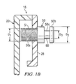
- FIGURE 1B is diagram of a section view of electronic device 10 taken along the line 1B-1B of FIGURE 1A .
- post 50 comprises a base portion 50a, a cap 50b and an intermediate portion 50c disposed between base portion 50a and cap 50b.
- base 50a and cap 50b each comprise diameters D1 and D2 larger than diameter D3 of intermediate portion 50c such that intermediate portion D3 forms an annular recess 80 engagable to releasably secure post 50 in a particular position.
- post 50 is configured generally in the shape of an "I"; however, it should be understood that post 50 may be otherwise configured such as, for example, "T"-shaped such that cap 50b comprises a diameter D2 larger than the diameters D1 and D3 of base portion 50a and intermediate portion 50c, respectively.
- bezel 28 is secured to housing 20 of display member 16 via post 50.
- base portion 50a comprises a threaded exterior surface 51 for engagement with bezel 28 and housing 20 of display member 16 to secure bezel 28 to display member 16.
- post 50 forms a part of locking system 12 while also functioning to secure bezel 28 to display device 16, which obviates the need for a separate and dedicated screw/connector for bezel 28.
- other methods of attaching post 50 to display member 16 are available, such as, but not limited to, frictionally attaching post 50 to display member 16. While post 50 is illustrated and described in connection with FIGURE 1B , it should be understood that post 48 is configured in a similar manner.
- FIGURE 2 is a diagram illustrating a portion of locking system 12 disposed in base member 18 of FIGURES 1A and 1B .
- locking system 12 comprises a latch 13 comprising a pair of slider arms 58 and 60 movable in response to actuation of a latch button 62.
- Slider arms 58 and 60 each comprise outwardly extending extensions 59 and 61, configured to engage biasing mechanisms 68 and 70, respectively.
- biasing mechanisms 68 and 70 exert forces on extensions 59 and 61, respectively, to inwardly bias slider arms 58 and 60 in the directions of arrows 64 and 66.
- Slider arms 58 and 60 each comprise slots 72 and 74 configured to receive posts 48 and 50, respectively.
- slider arms 58 and 60 are inwardly biased such that the edges 76 and 78 of openings 72 and 74, respectively, are inserted within annular recesses 80 to secure posts 48 and 50 within openings 72 and 74 to secure display member 16 to base member 18.
- locking system 12 is illustrated in a locked position to securely fasten display member 16 in a fixed position relative to base member 18.
- latch 13 may be otherwise configured to engage posts 48 and 50 to secure display member 16 to base member 18.
- latch 13 may reside on a single side of post 48 and/or 50 and engage and disengage annular recesses 80 via back and for the movement in the directions indicated by arrows 82 and 83.
- annular recesses 80 may be otherwise configured (e.g., configured to extend partially around a circumference of posts 48 and 50).
- latch 13 In operation, in response to button 62 being depressed or otherwise actuated in the direction of arrow 82, latch 13 is moved to an unlocked position.
- button 62 exerts a force on angled surfaces 84 and 86 of slider arms 58 and 60, respectively, to move slider arms 58 and 60 in the directions of arrows 88 and 90, thereby compressing biasing mechanisms 68 and 70.
- Movement of slider arms 58 and 60 positions and/or otherwise moves edges 76 and 78 outwardly from recesses 80 to facilitate removal of posts 48 and 50 from openings 72 and 74, respectively, to enable release of display member 16 from base member 18.
- a biasing mechanism 92 outwardly biases button 62 in the direction of arrow 83 to return button 62 to its unactuated position.
- FIG. 3A is a diagram illustrating a portion of locking system 12 of FIGS. 1A and 1B in which cap 56b is illustrated in an extended position (e.g., cap 56b is flush or substantially flush with working surface 36 and encloses opening 54).
- FIG. 3B is a diagram illustrating locking system 12 of FIG. 3A in a partially retracted position (e.g., cap 56b partially retracted within housing 34).
- FIG. 3C is a diagram illustrating locking system 12 of FIG. 3A in a fully retracted position (e.g., cap 56b positioned below slider arm 60 to enable movement of slider arm 60 in the directions of arrows 66 and 90). While slider arm 60 is only illustrated in FIGS. 3A-3C , it should be understood that slider arm 58 operates in a similar manner.
- cap 56b is upwardly biased in the direction of arrow 94 by a biasing mechanism 96.
- cap 56b is disposed on a cap support member 98 having an arm 100 slideably engagable with a ramp 102 disposed on extension 61 of slider arm 60.
- biasing mechanism 96 exerts a force on support member 98 in the direction of arrow 94, thereby causing arm 100 to slideably engage ramp 102 to urge arm 60 in the direction of arrow 90, thereby compressing biasing mechanism 70.
- groove 74 is aligned with post 50 to enable insertion of post 50 therethrough.
- cap support member 98 compresses biasing mechanism 96 to enable movement/lowering of arm 100 in the direction of arrow 95.
- biasing mechanism 70 exerts a force on extension 61 of slider arm 60 to gradually urge slider arm 60 in the direction of arrow 66. Accordingly, as arm 100 moves downward, the engagement and/or or movement of arm 100 along ramp 102 enables biasing mechanism 70 to urge slider arm 60 in the direction of arrow 66.
- biasing mechanism 70 urges slider arm 60 such that edge 78 of opening 74 is inserted within recess 80 of post 50 to secure display member 16 to base member 18 to prevent movement of display member 16 in the direction of arrow 94. While display member 16 is secured to base member 18, biasing mechanism 70 continuously urges slider arm 60 in the direction of arrow 66 to continuously position edge 78 inside recess 80 such that latch 13 securely fastens display member 16 to base member 18.
- button 62 ( FIGURE 2 ) is actuated to cause slider arm 60 to move in the direction of arrow 90 to remove edge 78 from recess 80 to facilitate removal of posts 48 and 50, respectively, from housing 34.
- latch 13 upon actuation of button 62, latch 13 automatically separates and/or lifts display member 16 a predetermined distance from base member 18 to facilitate opening thereof by a user. For example, when button 62 is actuated to remove edge 78 from within recess 80, the potential energy stored by biasing mechanism 96 forces movement of support system 98 and, thus, post 50 in the direction of arrow 94, which raises/lifts display member 16 away from base member 18 a predetermined distance to enable a user to easily grip and rotate display member 16 to the open position. Furthermore, when transitioning display member 16 toward base member 18 to secure display member 16 to base member 18, latch 13 prevents and/or substantially reduces the likelihood of abrupt contact between display member 16 and base member 18 by decelerating movement of display member 16.
- biasing mechanism 96 exerts a biasing force on support system 98 such that as post 50 contacts cap 56b, biasing mechanism 96 is compressed and stores potential energy therein, thereby resisting the movement of display member 16 toward base member 18 and substantially reducing or eliminating the likelihood of abrupt contact between display member 16 and base member 18.
- embodiments provide a latch 12 comprising posts 48 and 50 extending outwardly from display member 16 to enable electronic device 10 to be securely fastened in a closed position.
- Posts 48 and 50 are configured to extend outwardly from display member 16 to reduce and/or eliminate the likelihood of foreign objects, such as clothing or jewelry, catching onto posts 48 and 50.
- posts 48 and 50 are coupleable to display member 16 to enable bezel 28 to be secured to display device 16 without requiring additional and/or dedicated attachment mechanisms.
Landscapes
- Engineering & Computer Science (AREA)
- Computer Hardware Design (AREA)
- Theoretical Computer Science (AREA)
- Physics & Mathematics (AREA)
- Human Computer Interaction (AREA)
- General Engineering & Computer Science (AREA)
- General Physics & Mathematics (AREA)
- Mathematical Physics (AREA)
- Mechanical Engineering (AREA)
- Casings For Electric Apparatus (AREA)
- Devices For Indicating Variable Information By Combining Individual Elements (AREA)
Applications Claiming Priority (2)
| Application Number | Priority Date | Filing Date | Title |
|---|---|---|---|
| US11/786,402 US7609514B2 (en) | 2007-04-11 | 2007-04-11 | Electronic device locking system |
| PCT/US2008/002275 WO2008127506A1 (en) | 2007-04-11 | 2008-02-19 | Electronic device locking system |
Publications (3)
| Publication Number | Publication Date |
|---|---|
| EP2135151A1 EP2135151A1 (en) | 2009-12-23 |
| EP2135151A4 EP2135151A4 (en) | 2013-04-10 |
| EP2135151B1 true EP2135151B1 (en) | 2016-01-06 |
Family
ID=39853517
Family Applications (1)
| Application Number | Title | Priority Date | Filing Date |
|---|---|---|---|
| EP08725868.7A Not-in-force EP2135151B1 (en) | 2007-04-11 | 2008-02-19 | Electronic device locking system |
Country Status (7)
| Country | Link |
|---|---|
| US (1) | US7609514B2 (pt) |
| EP (1) | EP2135151B1 (pt) |
| JP (1) | JP2010524122A (pt) |
| CN (1) | CN101657777B (pt) |
| BR (1) | BRPI0809176A2 (pt) |
| TW (1) | TW200844315A (pt) |
| WO (1) | WO2008127506A1 (pt) |
Families Citing this family (29)
| Publication number | Priority date | Publication date | Assignee | Title |
|---|---|---|---|---|
| TWI315770B (en) * | 2007-03-22 | 2009-10-11 | Qisda Corp | Coupling mechanism and display device using the same |
| US8174837B2 (en) * | 2007-04-27 | 2012-05-08 | Hewlett-Packard Development Company, L.P. | Wireless enable/disable locking system |
| JP4949190B2 (ja) * | 2007-10-18 | 2012-06-06 | レノボ・シンガポール・プライベート・リミテッド | 携帯式コンピュータおよび筐体構造 |
| CN101636052B (zh) * | 2008-07-25 | 2012-05-30 | 鸿富锦精密工业(深圳)有限公司 | 电子设备 |
| TWI381795B (zh) * | 2008-10-08 | 2013-01-01 | Compal Electronics Inc | 攜帶式電子裝置的閂鎖結構 |
| TW201022885A (en) * | 2008-12-03 | 2010-06-16 | Compal Electronics Inc | Method for operating locking device |
| TW201032693A (en) * | 2009-02-24 | 2010-09-01 | Compal Electronics Inc | Fastening mechanism |
| JP2010250513A (ja) * | 2009-04-14 | 2010-11-04 | Fujitsu Ltd | 電子機器 |
| CN101868128B (zh) * | 2009-04-16 | 2012-10-17 | 深圳富泰宏精密工业有限公司 | 便携式电子装置 |
| TWI386776B (zh) * | 2009-08-10 | 2013-02-21 | Aten Int Co Ltd | 連動機構與應用其之鍵盤-螢幕-滑鼠模組 |
| TWM372621U (en) * | 2009-09-07 | 2010-01-11 | Quanta Comp Inc | A vacuum type latch device and a clam type electrical device with the same |
| US20110068587A1 (en) * | 2009-09-23 | 2011-03-24 | Apple Inc. | Integrated latch |
| EP2322382A1 (en) * | 2009-11-16 | 2011-05-18 | Zadi S.p.A. | Locking system for cases and vehicle roof boxes |
| CN102238832A (zh) * | 2010-04-29 | 2011-11-09 | 深圳富泰宏精密工业有限公司 | 盖体卡锁结构 |
| US20140133080A1 (en) * | 2012-11-15 | 2014-05-15 | Samsung Electronics Co., Ltd. | Detachable electronic device and connection apparatus usable with the same |
| USD706763S1 (en) * | 2013-01-24 | 2014-06-10 | Hewlett-Packard Development Company, L.P. | Computer |
| USD706764S1 (en) * | 2013-01-24 | 2014-06-10 | Hewlett-Packard Development Company, L.P. | Computer |
| USD706765S1 (en) * | 2013-01-24 | 2014-06-10 | Hewlett-Packard Development Company, L.P. | Computer |
| KR102046867B1 (ko) | 2013-04-16 | 2019-11-20 | 삼성전자주식회사 | 전자 장치 및 그 결합 구조 |
| US9237664B2 (en) * | 2013-11-15 | 2016-01-12 | Dell Products L.P. | Multi-module keying system |
| CN104913170A (zh) * | 2014-03-11 | 2015-09-16 | 冠捷投资有限公司 | 显示装置的吊挂系统 |
| TWI510167B (zh) * | 2014-05-30 | 2015-11-21 | Pegatron Corp | 固定裝置及其應用之電腦裝置 |
| EP3161578B1 (en) * | 2014-06-27 | 2020-12-09 | Hewlett-Packard Development Company, L.P. | Computing device with a rotatable display member |
| US10566715B2 (en) * | 2017-09-29 | 2020-02-18 | Apple Inc. | Reduced net force electrical connectors |
| US10905018B2 (en) * | 2018-11-08 | 2021-01-26 | Wirepath Home Systems, Llc | Television enclosures and related systems and methods |
| US11144271B1 (en) * | 2018-12-08 | 2021-10-12 | Screen It Up Corp. | Systems for moveable computer display devices |
| TWI748704B (zh) * | 2020-10-23 | 2021-12-01 | 華碩電腦股份有限公司 | 轉軸結構與電子裝置 |
| TWI776282B (zh) * | 2020-11-19 | 2022-09-01 | 緯穎科技服務股份有限公司 | 組裝結構及機箱 |
| TWI847753B (zh) * | 2022-02-11 | 2024-07-01 | 神基科技股份有限公司 | 電子裝置 |
Family Cites Families (23)
| Publication number | Priority date | Publication date | Assignee | Title |
|---|---|---|---|---|
| JPH01165682A (ja) | 1987-12-21 | 1989-06-29 | Toagosei Chem Ind Co Ltd | 接着剤組成物 |
| JPH01174977A (ja) * | 1987-12-29 | 1989-07-11 | Matsushita Electric Ind Co Ltd | 動作検出装置 |
| JPH062292Y2 (ja) * | 1988-05-12 | 1994-01-19 | 株式会社ピーエフユー | ロック機構 |
| JPH0710541Y2 (ja) * | 1988-05-30 | 1995-03-08 | 株式会社リコー | ケース係止機構 |
| JPH032383U (pt) * | 1989-05-26 | 1991-01-10 | ||
| JP2834770B2 (ja) * | 1989-05-29 | 1998-12-14 | 四国化成工業株式会社 | 銅及び銅合金の表面処理方法 |
| US5205017A (en) * | 1992-03-18 | 1993-04-27 | Jetta Computers Co., Ltd. | Notebook computer top cover mounting hardware |
| JPH0738505B2 (ja) | 1992-10-12 | 1995-04-26 | インターナショナル・ビジネス・マシーンズ・コーポレイション | 蓋付き構造体、及び、情報処理装置 |
| KR100252255B1 (ko) * | 1997-04-15 | 2000-04-15 | 윤종용 | 휴대용 컴퓨터 시스템을 위한 전원 제어 방법 |
| KR19990000303A (ko) * | 1997-06-04 | 1999-01-15 | 윤종용 | 노트북 컴퓨터의 개폐장치 |
| KR200287289Y1 (ko) * | 1999-03-13 | 2002-08-29 | 삼성전자 주식회사 | 전자 장치를 위한 잠금장치의 구조 |
| KR20000018161A (ko) | 2000-01-15 | 2000-04-06 | 윤종용 | 네트워크를 통하여 이동통신기기의 이용자에게광고서비스를 제공하는 방법 및 그 방법을 기록한컴퓨터로 읽을수 있는 기록매체 |
| KR100688976B1 (ko) | 2001-02-06 | 2007-03-08 | 삼성전자주식회사 | 휴대용 컴퓨터 |
| KR100418707B1 (ko) * | 2001-07-13 | 2004-02-11 | 삼성전자주식회사 | 휴대용컴퓨터 |
| TW551518U (en) * | 2001-09-07 | 2003-09-01 | Wistron Corp | Electronic equipment having dual-way fastened apparatus |
| US6762928B2 (en) * | 2002-08-19 | 2004-07-13 | Quanta Computer Inc. | Automatic lifting apparatus for liquid crystal display module of notebook computer |
| KR100486274B1 (ko) * | 2002-10-24 | 2005-04-29 | 삼성전자주식회사 | 집적회로 장치 설계용 네트리스트 작성 방법 |
| JP2004234194A (ja) * | 2003-01-29 | 2004-08-19 | Toshiba Corp | 電子機器 |
| JP2004326440A (ja) | 2003-04-24 | 2004-11-18 | Sharp Corp | 情報処理装置 |
| CN2731522Y (zh) * | 2004-09-28 | 2005-10-05 | 联想(北京)有限公司 | 笔记本电脑钩扣结构 |
| CN2763867Y (zh) * | 2004-12-04 | 2006-03-08 | 鸿富锦精密工业(深圳)有限公司 | 笔记本电脑上盖锁固装置 |
| US20060133019A1 (en) * | 2004-12-21 | 2006-06-22 | Fuminori Yamazaki | Latch assembly for an electronic device |
| TWI295916B (en) * | 2005-06-13 | 2008-04-11 | Asustek Comp Inc | Case structure of portable electronic device |
-
2007
- 2007-04-11 US US11/786,402 patent/US7609514B2/en active Active
-
2008
- 2008-02-19 EP EP08725868.7A patent/EP2135151B1/en not_active Not-in-force
- 2008-02-19 BR BRPI0809176-5A patent/BRPI0809176A2/pt not_active Application Discontinuation
- 2008-02-19 CN CN2008800116246A patent/CN101657777B/zh not_active Expired - Fee Related
- 2008-02-19 WO PCT/US2008/002275 patent/WO2008127506A1/en not_active Ceased
- 2008-02-19 JP JP2010502998A patent/JP2010524122A/ja active Pending
- 2008-03-11 TW TW097108466A patent/TW200844315A/zh unknown
Also Published As
| Publication number | Publication date |
|---|---|
| CN101657777B (zh) | 2013-05-29 |
| US7609514B2 (en) | 2009-10-27 |
| WO2008127506A1 (en) | 2008-10-23 |
| BRPI0809176A2 (pt) | 2014-09-16 |
| EP2135151A1 (en) | 2009-12-23 |
| TW200844315A (en) | 2008-11-16 |
| EP2135151A4 (en) | 2013-04-10 |
| CN101657777A (zh) | 2010-02-24 |
| US20080253094A1 (en) | 2008-10-16 |
| JP2010524122A (ja) | 2010-07-15 |
Similar Documents
| Publication | Publication Date | Title |
|---|---|---|
| EP2135151B1 (en) | Electronic device locking system | |
| US5918956A (en) | Computer cabinet latching mechanism | |
| US6469900B2 (en) | Apparatus for locking and ejecting a module device | |
| US8172282B2 (en) | Computing device latching assembly | |
| US7909629B2 (en) | Computer device with retractable connector | |
| US8111511B2 (en) | Electronic device physical security component | |
| JPH0762417B2 (ja) | ドアラッチ装置 | |
| EP4198684B1 (en) | Circuit board module and release component | |
| US9326397B2 (en) | Attachment device, electronic apparatus, and locking mechanism | |
| JP2001067146A (ja) | コンピューター用拡張ユニットのロック装置 | |
| CN101472412A (zh) | 翻盖型电子装置外壳 | |
| CN2831218Y (zh) | 电子装置上盖锁固装置 | |
| CN101276236B (zh) | 电子装置承载座 | |
| TWI381790B (zh) | 閂鎖機構 | |
| CN210865426U (zh) | 一种能够快速锁扣的显示装置 | |
| CN2599633Y (zh) | 易开启的扣合装置 | |
| CN102044642B (zh) | 闩锁机构 | |
| US20190086973A1 (en) | Computing devices | |
| TW201416825A (zh) | 保護結構及電子元件保護結構 | |
| JP4253956B2 (ja) | ポートリプリケータ | |
| CN102339100B (zh) | 具有扣锁结构的电子装置及其扣锁元件 | |
| CN203026568U (zh) | 一种开关结构 | |
| CN201035522Y (zh) | 无线鼠标 | |
| CN108222708B (zh) | 方形电脑锁 | |
| CN219536538U (zh) | 防护外壳组件和取电盒 |
Legal Events
| Date | Code | Title | Description |
|---|---|---|---|
| PUAI | Public reference made under article 153(3) epc to a published international application that has entered the european phase |
Free format text: ORIGINAL CODE: 0009012 |
|
| 17P | Request for examination filed |
Effective date: 20091007 |
|
| AK | Designated contracting states |
Kind code of ref document: A1 Designated state(s): AT BE BG CH CY CZ DE DK EE ES FI FR GB GR HR HU IE IS IT LI LT LU LV MC MT NL NO PL PT RO SE SI SK TR |
|
| DAX | Request for extension of the european patent (deleted) | ||
| A4 | Supplementary search report drawn up and despatched |
Effective date: 20130311 |
|
| RIC1 | Information provided on ipc code assigned before grant |
Ipc: G06F 1/16 20060101AFI20130305BHEP |
|
| 17Q | First examination report despatched |
Effective date: 20131008 |
|
| GRAP | Despatch of communication of intention to grant a patent |
Free format text: ORIGINAL CODE: EPIDOSNIGR1 |
|
| INTG | Intention to grant announced |
Effective date: 20150901 |
|
| GRAS | Grant fee paid |
Free format text: ORIGINAL CODE: EPIDOSNIGR3 |
|
| GRAA | (expected) grant |
Free format text: ORIGINAL CODE: 0009210 |
|
| AK | Designated contracting states |
Kind code of ref document: B1 Designated state(s): AT BE BG CH CY CZ DE DK EE ES FI FR GB GR HR HU IE IS IT LI LT LU LV MC MT NL NO PL PT RO SE SI SK TR |
|
| REG | Reference to a national code |
Ref country code: GB Ref legal event code: FG4D |
|
| REG | Reference to a national code |
Ref country code: CH Ref legal event code: EP |
|
| REG | Reference to a national code |
Ref country code: IE Ref legal event code: FG4D |
|
| REG | Reference to a national code |
Ref country code: AT Ref legal event code: REF Ref document number: 769377 Country of ref document: AT Kind code of ref document: T Effective date: 20160215 |
|
| REG | Reference to a national code |
Ref country code: DE Ref legal event code: R096 Ref document number: 602008041807 Country of ref document: DE |
|
| REG | Reference to a national code |
Ref country code: LT Ref legal event code: MG4D |
|
| REG | Reference to a national code |
Ref country code: NL Ref legal event code: MP Effective date: 20160106 |
|
| REG | Reference to a national code |
Ref country code: AT Ref legal event code: MK05 Ref document number: 769377 Country of ref document: AT Kind code of ref document: T Effective date: 20160106 |
|
| PG25 | Lapsed in a contracting state [announced via postgrant information from national office to epo] |
Ref country code: BE Free format text: LAPSE BECAUSE OF NON-PAYMENT OF DUE FEES Effective date: 20160229 |
|
| PG25 | Lapsed in a contracting state [announced via postgrant information from national office to epo] |
Ref country code: NL Free format text: LAPSE BECAUSE OF FAILURE TO SUBMIT A TRANSLATION OF THE DESCRIPTION OR TO PAY THE FEE WITHIN THE PRESCRIBED TIME-LIMIT Effective date: 20160106 |
|
| PG25 | Lapsed in a contracting state [announced via postgrant information from national office to epo] |
Ref country code: FI Free format text: LAPSE BECAUSE OF FAILURE TO SUBMIT A TRANSLATION OF THE DESCRIPTION OR TO PAY THE FEE WITHIN THE PRESCRIBED TIME-LIMIT Effective date: 20160106 Ref country code: GR Free format text: LAPSE BECAUSE OF FAILURE TO SUBMIT A TRANSLATION OF THE DESCRIPTION OR TO PAY THE FEE WITHIN THE PRESCRIBED TIME-LIMIT Effective date: 20160407 Ref country code: HR Free format text: LAPSE BECAUSE OF FAILURE TO SUBMIT A TRANSLATION OF THE DESCRIPTION OR TO PAY THE FEE WITHIN THE PRESCRIBED TIME-LIMIT Effective date: 20160106 Ref country code: NO Free format text: LAPSE BECAUSE OF FAILURE TO SUBMIT A TRANSLATION OF THE DESCRIPTION OR TO PAY THE FEE WITHIN THE PRESCRIBED TIME-LIMIT Effective date: 20160406 Ref country code: IT Free format text: LAPSE BECAUSE OF FAILURE TO SUBMIT A TRANSLATION OF THE DESCRIPTION OR TO PAY THE FEE WITHIN THE PRESCRIBED TIME-LIMIT Effective date: 20160106 Ref country code: ES Free format text: LAPSE BECAUSE OF FAILURE TO SUBMIT A TRANSLATION OF THE DESCRIPTION OR TO PAY THE FEE WITHIN THE PRESCRIBED TIME-LIMIT Effective date: 20160106 |
|
| PG25 | Lapsed in a contracting state [announced via postgrant information from national office to epo] |
Ref country code: LV Free format text: LAPSE BECAUSE OF FAILURE TO SUBMIT A TRANSLATION OF THE DESCRIPTION OR TO PAY THE FEE WITHIN THE PRESCRIBED TIME-LIMIT Effective date: 20160106 Ref country code: SE Free format text: LAPSE BECAUSE OF FAILURE TO SUBMIT A TRANSLATION OF THE DESCRIPTION OR TO PAY THE FEE WITHIN THE PRESCRIBED TIME-LIMIT Effective date: 20160106 Ref country code: AT Free format text: LAPSE BECAUSE OF FAILURE TO SUBMIT A TRANSLATION OF THE DESCRIPTION OR TO PAY THE FEE WITHIN THE PRESCRIBED TIME-LIMIT Effective date: 20160106 Ref country code: IS Free format text: LAPSE BECAUSE OF FAILURE TO SUBMIT A TRANSLATION OF THE DESCRIPTION OR TO PAY THE FEE WITHIN THE PRESCRIBED TIME-LIMIT Effective date: 20160506 Ref country code: PT Free format text: LAPSE BECAUSE OF FAILURE TO SUBMIT A TRANSLATION OF THE DESCRIPTION OR TO PAY THE FEE WITHIN THE PRESCRIBED TIME-LIMIT Effective date: 20160506 Ref country code: PL Free format text: LAPSE BECAUSE OF FAILURE TO SUBMIT A TRANSLATION OF THE DESCRIPTION OR TO PAY THE FEE WITHIN THE PRESCRIBED TIME-LIMIT Effective date: 20160106 Ref country code: LT Free format text: LAPSE BECAUSE OF FAILURE TO SUBMIT A TRANSLATION OF THE DESCRIPTION OR TO PAY THE FEE WITHIN THE PRESCRIBED TIME-LIMIT Effective date: 20160106 |
|
| REG | Reference to a national code |
Ref country code: CH Ref legal event code: PL |
|
| REG | Reference to a national code |
Ref country code: DE Ref legal event code: R097 Ref document number: 602008041807 Country of ref document: DE |
|
| PG25 | Lapsed in a contracting state [announced via postgrant information from national office to epo] |
Ref country code: CH Free format text: LAPSE BECAUSE OF NON-PAYMENT OF DUE FEES Effective date: 20160229 Ref country code: EE Free format text: LAPSE BECAUSE OF FAILURE TO SUBMIT A TRANSLATION OF THE DESCRIPTION OR TO PAY THE FEE WITHIN THE PRESCRIBED TIME-LIMIT Effective date: 20160106 Ref country code: DK Free format text: LAPSE BECAUSE OF FAILURE TO SUBMIT A TRANSLATION OF THE DESCRIPTION OR TO PAY THE FEE WITHIN THE PRESCRIBED TIME-LIMIT Effective date: 20160106 Ref country code: LI Free format text: LAPSE BECAUSE OF NON-PAYMENT OF DUE FEES Effective date: 20160229 Ref country code: MC Free format text: LAPSE BECAUSE OF FAILURE TO SUBMIT A TRANSLATION OF THE DESCRIPTION OR TO PAY THE FEE WITHIN THE PRESCRIBED TIME-LIMIT Effective date: 20160106 |
|
| PLBE | No opposition filed within time limit |
Free format text: ORIGINAL CODE: 0009261 |
|
| STAA | Information on the status of an ep patent application or granted ep patent |
Free format text: STATUS: NO OPPOSITION FILED WITHIN TIME LIMIT |
|
| REG | Reference to a national code |
Ref country code: FR Ref legal event code: ST Effective date: 20161028 |
|
| PG25 | Lapsed in a contracting state [announced via postgrant information from national office to epo] |
Ref country code: RO Free format text: LAPSE BECAUSE OF FAILURE TO SUBMIT A TRANSLATION OF THE DESCRIPTION OR TO PAY THE FEE WITHIN THE PRESCRIBED TIME-LIMIT Effective date: 20160106 Ref country code: SK Free format text: LAPSE BECAUSE OF FAILURE TO SUBMIT A TRANSLATION OF THE DESCRIPTION OR TO PAY THE FEE WITHIN THE PRESCRIBED TIME-LIMIT Effective date: 20160106 Ref country code: CZ Free format text: LAPSE BECAUSE OF FAILURE TO SUBMIT A TRANSLATION OF THE DESCRIPTION OR TO PAY THE FEE WITHIN THE PRESCRIBED TIME-LIMIT Effective date: 20160106 |
|
| REG | Reference to a national code |
Ref country code: IE Ref legal event code: MM4A |
|
| 26N | No opposition filed |
Effective date: 20161007 |
|
| PG25 | Lapsed in a contracting state [announced via postgrant information from national office to epo] |
Ref country code: BE Free format text: LAPSE BECAUSE OF FAILURE TO SUBMIT A TRANSLATION OF THE DESCRIPTION OR TO PAY THE FEE WITHIN THE PRESCRIBED TIME-LIMIT Effective date: 20160106 |
|
| PG25 | Lapsed in a contracting state [announced via postgrant information from national office to epo] |
Ref country code: FR Free format text: LAPSE BECAUSE OF NON-PAYMENT OF DUE FEES Effective date: 20160307 Ref country code: IE Free format text: LAPSE BECAUSE OF NON-PAYMENT OF DUE FEES Effective date: 20160219 |
|
| PG25 | Lapsed in a contracting state [announced via postgrant information from national office to epo] |
Ref country code: BG Free format text: LAPSE BECAUSE OF FAILURE TO SUBMIT A TRANSLATION OF THE DESCRIPTION OR TO PAY THE FEE WITHIN THE PRESCRIBED TIME-LIMIT Effective date: 20160406 Ref country code: SI Free format text: LAPSE BECAUSE OF FAILURE TO SUBMIT A TRANSLATION OF THE DESCRIPTION OR TO PAY THE FEE WITHIN THE PRESCRIBED TIME-LIMIT Effective date: 20160106 |
|
| PG25 | Lapsed in a contracting state [announced via postgrant information from national office to epo] |
Ref country code: MT Free format text: LAPSE BECAUSE OF FAILURE TO SUBMIT A TRANSLATION OF THE DESCRIPTION OR TO PAY THE FEE WITHIN THE PRESCRIBED TIME-LIMIT Effective date: 20160106 |
|
| PG25 | Lapsed in a contracting state [announced via postgrant information from national office to epo] |
Ref country code: HU Free format text: LAPSE BECAUSE OF FAILURE TO SUBMIT A TRANSLATION OF THE DESCRIPTION OR TO PAY THE FEE WITHIN THE PRESCRIBED TIME-LIMIT; INVALID AB INITIO Effective date: 20080219 Ref country code: CY Free format text: LAPSE BECAUSE OF FAILURE TO SUBMIT A TRANSLATION OF THE DESCRIPTION OR TO PAY THE FEE WITHIN THE PRESCRIBED TIME-LIMIT Effective date: 20160106 |
|
| PG25 | Lapsed in a contracting state [announced via postgrant information from national office to epo] |
Ref country code: MT Free format text: LAPSE BECAUSE OF FAILURE TO SUBMIT A TRANSLATION OF THE DESCRIPTION OR TO PAY THE FEE WITHIN THE PRESCRIBED TIME-LIMIT Effective date: 20160229 Ref country code: LU Free format text: LAPSE BECAUSE OF NON-PAYMENT OF DUE FEES Effective date: 20160219 Ref country code: TR Free format text: LAPSE BECAUSE OF FAILURE TO SUBMIT A TRANSLATION OF THE DESCRIPTION OR TO PAY THE FEE WITHIN THE PRESCRIBED TIME-LIMIT Effective date: 20160106 |
|
| PGFP | Annual fee paid to national office [announced via postgrant information from national office to epo] |
Ref country code: GB Payment date: 20220124 Year of fee payment: 15 Ref country code: DE Payment date: 20210528 Year of fee payment: 15 |
|
| REG | Reference to a national code |
Ref country code: DE Ref legal event code: R119 Ref document number: 602008041807 Country of ref document: DE |
|
| GBPC | Gb: european patent ceased through non-payment of renewal fee |
Effective date: 20230219 |
|
| PG25 | Lapsed in a contracting state [announced via postgrant information from national office to epo] |
Ref country code: GB Free format text: LAPSE BECAUSE OF NON-PAYMENT OF DUE FEES Effective date: 20230219 |
|
| PG25 | Lapsed in a contracting state [announced via postgrant information from national office to epo] |
Ref country code: GB Free format text: LAPSE BECAUSE OF NON-PAYMENT OF DUE FEES Effective date: 20230219 Ref country code: DE Free format text: LAPSE BECAUSE OF NON-PAYMENT OF DUE FEES Effective date: 20230901 |