EP2131167B1 - Vorrichtung zur Ermittlung des Ladezustandes von Fahrzeugen - Google Patents
Vorrichtung zur Ermittlung des Ladezustandes von Fahrzeugen Download PDFInfo
- Publication number
- EP2131167B1 EP2131167B1 EP20090007409 EP09007409A EP2131167B1 EP 2131167 B1 EP2131167 B1 EP 2131167B1 EP 20090007409 EP20090007409 EP 20090007409 EP 09007409 A EP09007409 A EP 09007409A EP 2131167 B1 EP2131167 B1 EP 2131167B1
- Authority
- EP
- European Patent Office
- Prior art keywords
- reference plate
- laser beam
- distance
- bogie
- vehicle
- Prior art date
- Legal status (The legal status is an assumption and is not a legal conclusion. Google has not performed a legal analysis and makes no representation as to the accuracy of the status listed.)
- Active
Links
Images

Classifications
-
- G—PHYSICS
- G01—MEASURING; TESTING
- G01G—WEIGHING
- G01G23/00—Auxiliary devices for weighing apparatus
- G01G23/007—Integrated arrangements for generating electrical power, e.g. solar cells
-
- G—PHYSICS
- G01—MEASURING; TESTING
- G01G—WEIGHING
- G01G19/00—Weighing apparatus or methods adapted for special purposes not provided for in the preceding groups
- G01G19/02—Weighing apparatus or methods adapted for special purposes not provided for in the preceding groups for weighing wheeled or rolling bodies, e.g. vehicles
- G01G19/04—Weighing apparatus or methods adapted for special purposes not provided for in the preceding groups for weighing wheeled or rolling bodies, e.g. vehicles for weighing railway vehicles
- G01G19/042—Weighing apparatus or methods adapted for special purposes not provided for in the preceding groups for weighing wheeled or rolling bodies, e.g. vehicles for weighing railway vehicles having electrical weight-sensitive devices
-
- G—PHYSICS
- G01—MEASURING; TESTING
- G01G—WEIGHING
- G01G19/00—Weighing apparatus or methods adapted for special purposes not provided for in the preceding groups
- G01G19/08—Weighing apparatus or methods adapted for special purposes not provided for in the preceding groups for incorporation in vehicles
- G01G19/12—Weighing apparatus or methods adapted for special purposes not provided for in the preceding groups for incorporation in vehicles having electrical weight-sensitive devices
-
- G—PHYSICS
- G01—MEASURING; TESTING
- G01G—WEIGHING
- G01G23/00—Auxiliary devices for weighing apparatus
-
- G—PHYSICS
- G01—MEASURING; TESTING
- G01G—WEIGHING
- G01G23/00—Auxiliary devices for weighing apparatus
- G01G23/18—Indicating devices, e.g. for remote indication; Recording devices; Scales, e.g. graduated
- G01G23/36—Indicating the weight by electrical means, e.g. using photoelectric cells
- G01G23/37—Indicating the weight by electrical means, e.g. using photoelectric cells involving digital counting
- G01G23/3728—Indicating the weight by electrical means, e.g. using photoelectric cells involving digital counting with wireless means
- G01G23/3735—Indicating the weight by electrical means, e.g. using photoelectric cells involving digital counting with wireless means using a digital network
- G01G23/3742—Indicating the weight by electrical means, e.g. using photoelectric cells involving digital counting with wireless means using a digital network using a mobile telephone network
-
- G—PHYSICS
- G01—MEASURING; TESTING
- G01S—RADIO DIRECTION-FINDING; RADIO NAVIGATION; DETERMINING DISTANCE OR VELOCITY BY USE OF RADIO WAVES; LOCATING OR PRESENCE-DETECTING BY USE OF THE REFLECTION OR RERADIATION OF RADIO WAVES; ANALOGOUS ARRANGEMENTS USING OTHER WAVES
- G01S17/00—Systems using the reflection or reradiation of electromagnetic waves other than radio waves, e.g. lidar systems
- G01S17/88—Lidar systems specially adapted for specific applications
-
- G—PHYSICS
- G01—MEASURING; TESTING
- G01S—RADIO DIRECTION-FINDING; RADIO NAVIGATION; DETERMINING DISTANCE OR VELOCITY BY USE OF RADIO WAVES; LOCATING OR PRESENCE-DETECTING BY USE OF THE REFLECTION OR RERADIATION OF RADIO WAVES; ANALOGOUS ARRANGEMENTS USING OTHER WAVES
- G01S7/00—Details of systems according to groups G01S13/00, G01S15/00, G01S17/00
- G01S7/003—Transmission of data between radar, sonar or lidar systems and remote stations
Definitions
- the invention relates to a device for determining the state of charge of vehicles, in particular railway vehicles.
- the previously known load sensors for freight cars do not meet the current requirements in rough practice. Accordingly, the load sensor should be maintenance-free and be viable in the harsh environment of transport and in particular the railroad. Furthermore, it is necessary that the device for determining the state of charge for various types of wagons are used, such. Waggons for bulk goods and wagons for car transport etc.
- the wheel bearings are arranged in a known manner from the outside accessible on the ends of the axles and are slightly ahead of the wheels, so that the wheel bearing, whose housing does not rotate with the wheel, is available as a reference point.
- the distance measuring device comprises a laser beam source fixed to the vehicle body and a laser beam sensor, as well as a reference plate fixed to the wheel bearing and illuminated by the laser beam source, the travel time of the laser beam being used to calculate the distance by means of a computing unit.
- FIG. 1 shows a schematic partial cross-section through a railway car, the railway elements are only indicated.
- FIG. 2 shows schematically in oblique view the arrangement on a bogie with two wheel axles,
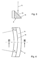
- FIG. 3 an enlarged view of the reference plate in section and
- FIG. 4 shows a plan view of this reference plate.
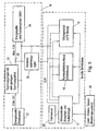
- FIG. 5 shows in the block diagram the integration of the device in a messaging system.
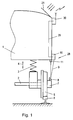
- FIG. 1 shows schematically the application of the device to a freight car.
- the vehicle body 1 serves to receive the load and is sprung relative to the axles 2 of the vehicle, which is indicated by the compression spring 3.
- the deflection is illustrated by the double arrow 4.
- the suspension and suspension of the wheels is made under the vehicle body.
- These may be pneumatic or hydraulic suspensions, flat springs or other suspension types. It is only essential that this reduces its distance from the wheel axle 2 due to the loading of the vehicle body.
- the wheel bearing 7 This sits on the axis 2 and houses the corresponding support for the rotating wheel 5 or the axis 2.
- the wheel bearing 7 is for maintenance, lubrication, etc. easily accessible from the outside and is therefore also available in a simple way for retrofitting with the device according to the invention.
- a reference plate 8 is arranged, which can be formed either by the wheel bearing housing itself or is an additional attached component.
- the reference plate 8 is arranged such that the laser beam 9 impinges on a laser beam source 10 and that light reflected from the reference plate can be picked up by the laser beam sensor 11.
- the laser beam source is shown as a separate unit to the laser beam sensor. This makes it possible to determine the optimal position for both parts of this distance measuring device 28 according to the structural conditions. But it may also be advantageous, the laser beam source and to combine the laser beam sensor into a common housing. In any case, it is important that the laser beam and its running time reach the required level again in the laser beam sensor. In this regard, it is not necessary that the reference plate 8 is formed particularly reflective. The modern sensor technology allows accurate readings on these lines with an accuracy in the millimeter range, wherein the reflection surface can also be dark or unreflective in the conventional sense.
- the signal of the distance measuring device 28 is fed via the line 29 to a location and communication device 30.
- This and all measuring arrangements are powered by a solar panel 21 with electricity.
- the device 30 sends the signal of the distance measuring device 28 and also other signals such as location data as an SMS, GPRS or UMTS message to a central receiving station.
- the function of the distance measuring device is self-explanatory.
- the vehicle body 1 When the vehicle is unloaded, the vehicle body 1 is maximally removed from the wheel axle 2 and thus also away from the reference plate 8.
- the distance measuring device consisting of the laser beam source 10, the laser beam sensor 11 and the associated accounting unit, measure a relatively long distance.
- the calculation of the distance is usually carried out by measuring the transit time between sending the laser beam to the laser beam source and arrival of this signal at the laser beam sensor 11 after reflection at the reference plate. 8
- FIG. 2 shown schematically, for better representation of the vehicle body and all other parts of the bogie are omitted. Shown are the four wheels 5 and the axis of rotation 12 of the bogie. When cornering, the entire bogie rotates with all four wheels about this axis of rotation 12, which is to be expected in the occurring in practice bending radii of the tracks, for example, a maximum deflection of 10 °. The deflection is also dependent on the wagon type.
- the reference plate 8 is provided on one of the wheel bearings. Furthermore, the laser beam 9, which is emitted by the laser beam source 10, can be seen schematically, as well as the reflection beam 13 to the laser beam sensor 11.
- the reference plate When turning the bogie about the axis of rotation 12, the reference plate describes a circular arc around the axis of rotation 12 and this arc is indicated by the reference numeral 14.
- the bow 14 is of course only theoretically available, since a bogie is never rotated by 360 ° while driving, but always undergoes only a small deflection, as mentioned above.
- the reference plate is preferably designed such that it covers a small section of the arch 14 in practice over the deflection of the bogie sweeps over, wherein the reference plate is formed such that no change in the distance measurement occurs by the fact of pivoting the bogie.
- the reference plate is bent, like the FIG. 4 can be seen in supervision.
- the radius corresponds to the radius R of the arc 14 to the axis of rotation 12 of the bogie and 14 is the impact track or light track of the laser light is located.
- the length of the reference plate must be adapted to the maximum deflection, ie the swivel angle of the bogie.
- FIG. 3 shows the cross section along the line III-III in FIG. 4 ,
- the reflection surface 15 is inclined relative to the horizontal, which brings with it the advantage that the freight car always falling down cargo or dirt does not stick but slips off.
- the measuring accuracy is not affected by this because the laser distance measuring devices of modern design are not affected by the reflection properties of the Reflection surface are dependent. In any case, at least one diffused scattered light is produced, which suffices for the measurement.
- a distance measuring device with respect to one of the wheel bearings of the vehicle is provided in each case. It may be advantageous to provide two or more such arrangements on a vehicle or wagon to have additional control.
- FIG. 5 shows a preferred application of the device according to the invention for determining the state of charge of a railway vehicle.
- This system is in the previously published Austrian patent application A 1466/2005 described in detail and this publication is expressly incorporated by reference.
- the device comprises the power supply 16, an electrical control unit 17, the communication module 18 and the locating module 19. Furthermore, a motion sensor 20 is provided. All of these parts, except for the solar panel, can be located inside the housing of the locating device.
- the solar panel 21 provides depending on the sunlight power with a voltage of 0 to 12 volts.
- the current of the solar panel is down regulated with the interposition of a reflux barrier diode by a supply voltage regulator 23 to the maximum voltage of the subsequent energy buffer 24.
- the maximum voltage of the energy buffer is 7.5 volts.
- a capacitor arrangement is preferably provided, which consists for example of three capacitors with 350 F connected in series.
- As a supply voltage regulator 23 such is used with the lowest possible voltage drop.
- the current decrease for the power supply of the device takes place at the branch point 25 between supply voltage regulator 23 and energy buffer 24 preferably via a constant voltage regulator 26.
- the constant voltage regulator 26 regulates the current down to an operating current of about 3.3 volts, which by the electronic control unit 17 is monitored.
- the electronic control unit 17 is also driven by the travel sensor 20, which is preferably a vibration sensor, which may also be housed in the housing.
- the ride sensor 20 responds when ride vibrations occur and indicate that the device is in motion with the object. Furthermore, it is reported when the object is stationary and thus no vibrations occur.
- the electronic control unit 17 operates with a wake-up logic.
- the wake-up logic is based on a periodic test of the motion sensor 20. When a preset value is repeatedly reached as the movement threshold, the device is supplied with operating voltage from the energy buffer or from the power source directly.
- the locating module 19 provides the locating coordinates and these are sent by the communication module 18 as a short message on the mobile telephone network. The short message is transmitted to a central short message receiver, not shown here, and further evaluated.
- the locating module 19 may be a GPS module and the communication module 18 may be a GSM module.
- these modules can be set up according to the respectively available global positioning systems (eg the future Gallileo system) and mobile telephone networks (eg also UMTS).
- the distance measuring device 28 also provides the distance measuring device 28 a load state reproducing signal to the controller 17.
- the loading state is sent together with the other data via the communication module and can be evaluated by a receiving station.
- the location and communication device can all the elements of FIG. 5 Also accommodate in a housing, with only the solar panel 21 and the laser beam source 10 and the sensor 11 must be arranged at appropriate locations of the vehicle.
- the invention is particularly suitable for retrofitting existing vehicle stock and is in combination with the solar power supply independent of external power sources.
- the reference plate is attached to the outer wheel bearing of a railway car, the maintenance is particularly facilitated.
- the entire arrangement of the distance measuring device 28 can also be provided at the place where the deflection of the vehicle body can be determined.
- the reference plate may be attached to an unsprung portion of the chassis, such as e.g. be arranged an axle bearing.
- the measurements of the distance measuring device can take place continuously or at certain time intervals.
- the measurement can also take place when requested by the microcontroller as a control unit 17.
Landscapes
- Physics & Mathematics (AREA)
- General Physics & Mathematics (AREA)
- Engineering & Computer Science (AREA)
- Computer Networks & Wireless Communication (AREA)
- Life Sciences & Earth Sciences (AREA)
- Sustainable Development (AREA)
- Sustainable Energy (AREA)
- Electromagnetism (AREA)
- Radar, Positioning & Navigation (AREA)
- Remote Sensing (AREA)
- Optical Radar Systems And Details Thereof (AREA)
- Length Measuring Devices By Optical Means (AREA)
Description
- Die Erfindung betrifft eine Vorrichtung zur Ermittlung des Ladezustandes von Fahrzeugen, inbesondere Eisenbahnfahrzeugen.
- Für Transportunternehmen ist es wünschenswert, den Beladungszustand von Fahrzeugen feststellen zu können, insbesondere wenn diese über ein weites Gebiet verstreut und schwer zugänglich sind. Dies ist z.B. bei Eisenbahnfahrzeugen und insbesondere bei Güterwaggons der Fall, die manchmal über große Gebiete verstreut längere Zeit abgestellt und dann wieder verschoben werden. Dabei ist vor allem die Information interessant, ob der Waggon beladen ist oder ob er nicht beladen ist. Eine genaue Information, zu welchem Nutzungsgrad ein Waggon tatsächlich beladen ist, muss bei der vorliegenden Erfindung nicht berücksichtigt werden, kann aber durchaus auch zu diesem Ergebnis führen.
- Die bisher bekannten Beladungssensoren für Güterwaggons entsprechen nicht den derzeitigen Anforderungen in der rauen Praxis. Demzufolge soll der Beladungssensor wartungsfrei sein und im rauen Umfeld der Transportbeförderung und insbesondere der Eisenbahn überlebensfähig sein. Weiters ist es erforderlich, dass die Vorrichtung zur Ermittlung des Ladezustandes für verschiedene Waggontypen einsetzbar sind, wie z.B. Waggons für Schüttgut und auch Waggons für den Autotransport etc.
- Bekannt ist es geworden, Ultraschallsensoren zu verwenden, die vom Wagenaufbau auf die Schiene gerichtet sind. Nachteilig ist dabei, dass diese Sensoren in Kurven nicht verwendbar sind, weil sie neben der Schiene den Untergrund anpeilen und daher falsche Ergebnisse liefern. Überdies sind besonders an den Verladestellen die Schienen und das Geleise mit Unkraut überwuchert, wodurch die Messungen unbrauchbar werden. Wenn ein Waggon auf einer Weiche steht, ist diese Methode ebenfalls nicht anwendbar. Überdies sind Ultraschallsensoren sehr ungenau.
- Bei herkömmlichen Waggons liegt die Einfederung des gefederten Waggonaufbaus gegenüber dem ungefederten Fahrgestell beispielsweise nur bei etwa 7 cm, wobei dieser Wert von der Waggontype abhängt. Die Unterscheidung zwischen beladen und unbeladen erfordert also relativ genaue Messungen. Mechanische Messvorrichtungen, die den Abstand zwischen Waggonaufbau und Schiene oder Eisenbahnrad messen, haben sich in der Praxis nicht bewährt.
- Eine weitere bekannte Möglichkeit der Messung des Beladungszustandes liegt darin, im zentralen Lager des Drehgestells der Waggons einen piezzoelektrischen Drucksensor einzubauen. Dies ist jedoch nur bei einem Neubau eines Waggons sinnvoll, da ein Nachrüsten bestehender Waggons derart kostenintensiv wäre, dass ein solcher Umbau nicht zielführend ist. Weitere bekannte Vorrichtungen sind der
WO 02/16890 A1 US 3 428 139 undUS 5 735 580 zu entnehmen. - Die angeführten Nachteile können in überraschender Weise vermieden werden, wenn ein Distanzmessgerät zum Messen der Distanz zwischen Fahrzeugaufbau und Radlager vorgesehen ist. Unter Fahrzeugaufbau werden im vorliegenden Fall jene Teile des Fahrzeuges verstanden, die gegenüber den Radachsen oder Drehgestell gefedert sind und bei Beladung die Distanz zwischen Fahrzeugaufbau und Schiene bzw. den darauf rollenden Rädern verringert wird.
- Die Radlager sind in bekannter Weise von außen zugänglich auf den Enden der Achsen angeordnet und stehen von den Rädern etwas vor, sodass das Radlager, dessen Gehäuse sich nicht mit dem Rad mitdreht, als Referenzpunkt zur Verfügung steht.
- Das erfindungsgemäße Distanzmessgerät umfasst eine am Fahrzeugaufbau befestigte Laserstrahlquelle und einen Laserstrahlsensor, sowie eine am Radlager befestigte und von der Laserstrahlquelle angestrahlte Referenzplatte, wobei die Laufzeit des Laserstrahls zur Berechnung der Distanz mittels einer Recheneinheit herangezogen wird.
- Weitere Merkmale sind den Ansprüchen und der nachfolgenden Beschreibung sowie den Zeichnungen zu entnehmen.
- Im folgenden wird die Erfindung anhand eines Ausführungsbeispieles näher beschrieben.
Figur 1 zeigt einen schematischen Teil-Querschnitt durch einen Eisenbahnwaggon, wobei die Eisenbahnelemente nur angedeutet sind.Figur 2 zeigt schematisch im Schrägriss die Anordnung an einem Drehgestell mit zwei Radachsen,Figur 3 eine vergrößerte Darstellung der Referenzplatte im Schnitt undFigur 4 zeigt eine Aufsicht auf diese Referenzplatte.Figur 5 zeigt im Blockschaltbild die Einbindung der Vorrichtung in ein Nachrichtenübermittlungssystem. -
Figur 1 zeigt schematisch die Anwendung der Vorrichtung an einem Güterwaggon. Der Fahrzeugaufbau 1 dient zur Aufnahme der Beladung und ist gegenüber den Achsen 2 des Fahrzeuges gefedert, was durch die Druckfeder 3 angedeutet ist. Die Einfederung wird durch den Doppelpfeil 4 veranschaulicht. Für die vorliegende Erfindung ist es völlig unerheblich, auf welche Weise die Federung und Aufhängung der Räder unter dem Fahrzeugaufbau vorgenommen ist. Es kann sich um pneumatische oder hydraulische Federungen, um Plattfedern oder andere Federungstypen handeln. Wesentlich ist lediglich, dass durch die Beladung des Fahrzeugaufbaus dieser seinen Abstand gegenüber der Radachse 2 verringert. - Außerhalb des Rades 5, welches auf der Schiene 6 läuft, liegt das Radlager 7. Dieses sitzt auf der Achse 2 und beherbergt die entsprechende Lagerung für das sich drehende Rad 5 oder die Achse 2. Das Radlager 7 ist für die Wartung, Schmierung etc. von außen leicht zugänglich und steht daher auch auf einfacher Weise für das Nachrüsten mit der erfindungsgemäßen Vorrichtung zur Verfügung.
- Auf dem Gehäuse des Radlager 7 ist eine Referenzplatte 8 angeordnet, die entweder durch das Radlagergehäuse selbst gebildet werden kann oder ein zusätzlicher aufgesetzter Bauteil ist. Die Referenzplatte 8 ist derart angeordnet, dass der Laserstrahl 9 einer Laserstrahlquelle 10 auftrifft und dass von der Referenzplatte rückstrahlende Licht vom Laserstrahlsensor 11 aufgenommen werden kann.
- Im vorliegenden Ausführungsbeispiel ist die Laserstrahlquelle als getrennte Baueinheit zum Laserstrahlsensor dargestellt. Damit ist es möglich, gemäß den baulichen Gegebenheiten die jeweils optimale Position für beide Teile dieses Distanzmessgerätes 28 festzulegen. Es kann aber ebenso vorteilhaft sein, die Laserstrahlquelle und den Laserstrahlsensor in ein gemeinsames Gehäuse zu kombinieren. Wichtig ist jedenfalls, dass der Laserstrahl und dessen Laufzeit mit der nötigen Stärke wieder im Laserstrahlsensor einlangt. Diesbezüglich ist es nicht notwendig, dass die Referenzplatte 8 besonders reflektierend ausgebildet ist. Die moderne Sensortechnik erlaubt auf diesen Strecken genaue Ablesungen mit einer Genauigkeit im Millimeterbereich, wobei die Reflexionsfläche auch dunkel oder im herkömmlichen Sinn unreflektierend ausgebildet sein kann.
- Das Signal des Distanzmessgerätes 28 wird über die Leitung 29 einer Ortungs- und Kommunikationseinrichtung 30 zugeleitet. Dieses und alle Messanordnungen werden von einem Solarpanel 21 mit Strom versorgt. Die Einrichtung 30 sendet das Signal des Distanzmessgerätes 28 und auch andere Signale wie Ortungsdaten als SMS-, GPRS-, oder UMTS-Nachricht an eine zentrale Empfangsstation.
- Die Funktion des Distanzmessgerätes erklärt sich von selbst. Bei unbeladenem Zustand ist der Fahrzeugaufbau 1 maximal entfernt von der Radachse 2 und damit auch entfernt von der Referenzplatte 8. Somit wird das Distanzmessgerät, bestehend aus der Laserstrahlquelle 10, dem Laserstrahlsensor 11 und der zugehörigen Verrechnungseinheit, eine relativ lange Strecke messen. Die Berechnung der Strecke erfolgt üblicherweise durch die Messung der Laufzeit zwischen Absenden des Laserstrahls an der Laserstrahlquelle und Eintreffen dieses Signals am Laserstrahlsensor 11 nach Reflexion an der Referenzplatte 8.
- Bei Beladung des Fahrzeugaufbaus kommt es zu einer Kompression der Federung 3 und damit zu einer Verringerung des Abstandes zwischen Fahrzeugaufbau 1 und Radachse 2. Diese Verringerung bewirkt auch eine Verkürzung der Distanz zwischen der Laserstrahlquelle 10 und -sensor 11 und der Referenzplatte 8.
- Die zuvor beschriebenen Maßnahmen würden genügen, um eine ausreichend genaue Ermittlung des Beladungszustandes zu ermöglichen, wenn die Radachsen ohne Drehgestell am Fahrzeugaufbau angeordnet sind. Dies ist jedoch zumeist nicht der Fall und es sind die Güterwaggons mit Drehgestellen versehen, die üblicherweise zweiachsig sind. Eine solche Anordnung ist in
Figur 2 schematisch dargestellt, wobei zur besseren Darstellung der Fahrzeugaufbau und alle sonstigen Teile des Drehgestells weggelassen sind. Dargestellt sind die vier Räder 5 und die Drehachse 12 des Drehgestells. Bei einer Kurvenfahrt dreht sich das gesamte Drehgestell mit allen vier Rädern um diese Drehachse 12, wobei bei den in der Praxis vorkommenden Biegeradien der Geleise beispielsweise eine maximale Auslenkung von 10° zu erwarten ist. Die Auslenkung ist auch abhängig von der Waggontype. - Weiters sind die an einer Seite des Fahrzeuges sichtbaren Radlager 7 dargestellt, wobei auf einem der Radlager die Referenzplatte 8 vorgesehen ist. Weiters ist schematisch der Laserstrahl 9, der von der Laserstrahlquelle 10 ausgesendet wird, ersichtlich, wie auch der Reflexionsstrahl 13 zum Laserstrahlsensor 11.
- Beim Drehen des Drehgestells um die Drehachse 12 beschreibt die Referenzplatte einen Bogen kreisförmig um die Drehachse 12 und dieser Bogen ist mit dem Bezugszeichen 14 eingezeichnet. Der Bogen 14 ist selbstverständlich nur theoretisch vorhanden, da ein Drehgestell im Fahrbetrieb niemals um 360° gedreht wird, sondern immer nur eine geringe Auslenkung erfährt, wie oben erwähnt ist.
- Damit gemäß Erfindung die Feststellung des Beladungszustandes des Fahrzeuges auch dann erfolgt, wenn der Waggon in einer Kurve steht oder sich in Kurvenfahrt befindet, ist die Referenzplatte bevorzugt so ausgebildet, dass sie über die in der Praxis vorkommende Auslenkung des Drehgestells einen kleinen Abschnitt des Bogens 14 überstreicht, wobei die Referenzplatte derart ausgebildet ist, dass durch den Umstand des Verschwenkens des Drehgestells keine Änderung in der Distanzmessung eintritt. Für diesen Zweck ist die Referenzplatte gebogen, wie der
Figur 4 in Aufsicht zu entnehmen ist. Der Radius entspricht dem Radius R des Bogen 14 zur Drehachse 12 des Drehgestells und mit 14 ist die Auftreffspur oder Lichtspur des Laserlichtes eingezeichnet. Die Länge der Referenzplatte muss der maximalen Auslenkung, also dem Schwenkwinkel des Drehgestelles angepasst sein. -
Figur 3 zeigt den Querschnitt nach der Linie III-III inFigur 4 . Die Reflexionsfläche 15 ist gegenüber der Horizontalen schräggestellt, was den Vorteil mit sich bringt, dass das bei Güterwaggons immer herabfallende Ladegut oder auch Schmutz nicht haften bleibt sondern abrutscht. Die Messgenauigkeit wird dadurch nicht beeinflusst, weil die Laserdistanzmessgeräte moderner Bauart nicht von den Reflexionseigenschaften der Reflexionsfläche abhängig sind. Es entsteht in jedem Fall zumindest ein diffuses Streulicht, welches zur Messung genügt. - In den Zeichnungen ist jeweils ein Distanzmessgerät mit Bezug auf eines der Radlager des Fahrzeuges vorgesehen. Es kann vorteilhaft sein, zwei oder mehr solcher Anordnungen an einem Fahrzeug oder Waggon vorzusehen, um eine zusätzliche Kontrolle zu haben.
- Die
Figur 5 zeigt eine bevorzugte Anwendung der erfindungsgemäßen Vorrichtung zur Ermittlung des Ladezustandes eines Eisenbahnfahrzeuges. Dieses System ist in der vorveröffentlichten Österreichischen PatentanmeldungA 1466/2005 - Gemäß Blockschaltbild der
Figur 5 umfasst das Gerät die Energieversorgung 16, ein elektrisches Steuergerät 17, das Kommunikationsmodul 18 und das Ortungsmodul 19. Weiters ist ein Bewegungssensor 20 vorgesehen. Alle diese Teile können sich - ausgenommen das Solarpanel - innerhalb des Gehäuses des Ortungsgerätes befinden. - Das Solarpanel 21 liefert in Abhängigkeit von der Sonneneinstrahlung Strom mit einer Spannung von 0 bis 12 Volt. Der Strom des Solarpanels wird unter Zwischenschaltung einer Rückflusssperrdiode durch einen Speise-Spannungsregler 23 auf die Höchstspannung des nachfolgenden Energiepuffers 24 herabgeregelt. Im vorliegenden Fall ist die Höchstspannung des Energiepuffers 7,5 Volt. Als Energiepuffer wird bevorzugt eine Kondensatoranordnung vorgesehen, die zB aus drei Kondensatoren mit je 350 F in Serie geschaltet besteht. Als Speise-Spannungsregler 23 wird ein solcher mit möglichst geringem Spannungsabfall eingesetzt.
- Die Stromabnahme für die Stromversorgung des Gerätes erfolgt an der Verzweigungsstelle 25 zwischen Speise-Spannungsregler 23 und Energiepuffer 24 bevorzugt über einen Konstantspannungsregler 26. Solange genügend Spannung anliegt, regelt der Konstantspannungsregler 26 den Strom auf einen Betriebsstrom von etwa 3,3 Volt herunter, was durch das elektronische Steuergerät 17 überwacht wird.
- Gemäß
Figur 5 wird das elektronische Steuergerät 17 auch von dem Fahrtsensor 20 angesteuert, der in bevorzugter Weise ein Vibrationssensor ist, der ebenfalls im Gehäuse untergebracht sein kann. Der Fahrtsensor 20 spricht an, wenn Fahrtvibrationen auftreten und anzeigen, dass sich das Gerät gemeinsam mit dem Objekt in Bewegung befindet. Weiters wird gemeldet, wenn das Objekt steht und somit keine Vibrationen auftreten. - Das elektronische Steuergerät 17 arbeitet mit einer Aufwecklogik. Die Aufwecklogik basiert auf einer periodischen Prüfung des Bewegungssensors 20. Wenn ein voreingestellter Wert als Bewegungsschwelle wiederholt erreicht wird, wird das Gerät mit Betriebsspannung aus dem Energiepuffer oder aus der Energiequelle direkt versorgt. Das Ortungsmodul 19 liefert die Ortungskoordinaten und diese werden durch das Kommunikationsmodul 18 als Kurznachricht über das mobile Telefonnetz versendet. Die Kurznachricht wird an einen hier nicht dargestellten zentralen Kurznachrichtenempfänger übertragen und weiter ausgewertet.
- Das Ortungsmodul 19 kann ein GPS-Modul und das Kommunikationsmodul 18 ein GSM-Modul sein. Selbstverständlich können diese Module nach den jeweils zur Verfügung stehenden globalen Ortungssystemen (zB das künftige Gallileo-System) und mobilen Telefonnetzen (zB auch UMTS) eingerichtet sein.
- Gemäß vorliegender Erfindung und wie in
Figur 5 eingezeichnet, liefert auch das Distanzmessgerät 28 ein den Beladungszustand wiedergebendes Signal an das Steuergerät 17. Der Beladungszustand wird gemeinsam mit den anderen Daten über das Kommunikationsmodul abgeschickt und kann so von einer Empfangstation ausgewertet werden. Die Ortungs- und Kommunikationseinrichtung kann alle Elemente derFigur 5 auch in einem Gehäuse beherbergen, wobei nur das Solarpanel 21 und die Laserstrahlquelle 10 und der Sensor 11 an passenden Stellen des Fahrzeuges angeordnet werden müssen. - Wenn hier vor allem die Erfindung im Zusammenhang mit Güterwaggons beschrieben ist, kann sie doch für alle Fahrzeuge und auch mit den Fahrzeugen bewegten Aufbauten verwendet werden. Beispiele sind Lastkraftwägen und deren Anhänger, Sattelschlepperauflieger, Container auf Kraftfahrzeugen oder Eisenbahnwaggons etc.
- Die Erfindung eignet sich besonders für das Nachrüsten von bereits vorhandenem Fahrzeugbestand und ist bei Kombination mit der Solarstromversorgung unabhängig von externen Stromquellen.
- Wenn die Referenzplatte am außenliegenden Radlager eines Eisenbahnwaggons angebracht ist, wird die Wartung besonders erleichtert. Bei Fahrzeugen ohne außenliegende Radlager kann die gesamte Anordnung des Distanzmessgerätes 28 auch an jenem Ort vorgesehen werden, an der die Einfederung des Fahrzeugaufbaues feststellbar ist. Beispielsweise kann die Referenzplatte an einem ungefederten Teil des Fahrgestelles wie z.B. ein Achslager angeordnet sein.
- Die Messungen des Distanzmessgerätes können kontinuierlich oder in bestimmten Zeitabständen erfolgen. Die Messung kann auch bei Anforderung durch den Mikrocontroller als Steuergerät 17 erfolgen.
-
- 1.
- Fahrzeugaufbau
- 2.
- Achse
- 3.
- Druckfeder
- 4.
- Doppelpfeil
- 5.
- Rad
- 6.
- Schiene
- 7.
- Radlager
- 8.
- Referenzplatte
- 9.
- Laserstrahl
- 10.
- Laserstrahlquelle
- 11.
- Laserstrahlsensor
- 12.
- Drehachse
- 13.
- Reflexionsstrahl
- 14.
- Bogen
- 15.
- Reflexionsfläche
- 16.
- Energieversorgung
- 17.
- Steuergerät
- 18.
- Kommunikationsmodul
- 19.
- Ortungsmodul
- 20.
- Fahrtsensor
- 21.
- Solarpanel
- 22.
- Rückflusssperrdiode
- 23.
- Speise-Spannungsregler
- 24.
- Energiepuffer
- 25.
- Verzweigungsstelle
- 26.
- Konstantspannungsregler
- 27.
- elektrisches Steuergerät
- 28.
- Distanzmessgerät
- 29.
- Leitung
- 30.
- Ortungs- und Kommunikationseinrichtung
Claims (10)
- Vorrichtung zur Ermittlung des Ladezustandes von Fahrzeugen, insbesondere Eisenbahnfahrzeugen, wobei ein Distanzmessgerät (28) zum Messen der Distanz zwischen Fahrzeugaufbau (1) und Radlager (7) oder einem ungefederten Teil des Fahrgestelles vorgesehen ist, und das Distanzmessgerät (28) eine am Fahrzeugaufbau (1) befestigbare Laserstrahlquelle (10) und einen Laserstrahlsensor (11) sowie eine am Radlager (7) oder Teil des Fahrgestelles befestigbare und von der Laserstrahlquelle (10) angestrahlte Referenzplatte (8) umfasst und die Laufzeit des Laserstrahls (9) zur Berechnung der Distanz mittels einer Recheneinheit herangezogen wird, wobei die Referenzplatte (8) auf einem Radlager (7) anordenbur ist, das Bestandteil eines Drehgestelles inshesondere eines Eisenbahnwagons, ist, dadurch gekennzeichnet, dass die Referenzplatte (8) gebogen ist, wobei der Biegungsmittelpunkt mit der Drehachse (12) des Drehgestells des Fahrzeugs zusammenfällt.
- Vorrichtung nach Anspruch 1, dadurch gekennzeichnet, dass die Referenzplatte (8) zur Bestrahlung mit dem Laserlicht entlang eines Bogens (14) eingerichtet ist.
- Vorrichtung nach Anspruch 1 oder 2, dadurch gekennzeichnet, dass die Referenzplatte (8) eine Abmessung aufweist, die dem Schwenkwinkel des Drehgestells angepasst ist und ein Schwenken bevorzugt um wenigstens 5° und bevorzugt wenigstens 10° unter Beibehaltung der Bestrahlung zulässt.
- Vorrichtung nach einem der vorhergehenden Ansprüche, dadurch gekennzeichnet, dass die Referenzplatte (8) auf dem Radlager (7) gegenüber der Horizontalen schräggestellt und gebogen ist.
- Vorrichtung nach einem der Ansprüche 1 bis 4, dadurch gekennzeichnet, dass sie zu einer Distanzmessung in vorbestimmten Zeitabständen eingerichtet ist.
- Vorrichtung nach einem der Ansprüche 1 bis 5, dadurch gekennzeichnet, dass die Distanzmessung bei Anforderung durch ein Abfragesignal erfolgt.
- Vorrichtung nach einem der Ansprüche 1 bis 6, dadurch gekennzeichnet, dass die Stromversorgung durch einen solargespeisten Kondensatorstromspeicher erfolgt.
- Vorrichtung nach einem der Ansprüche 1 bis 7, dadurch gekennzeichnet, dass der von der Recheneinheit berechnete Ladezustand einer Sendeeinheit zur drahtlosen Nachrichtenübermittlung zugeleitet wird.
- Vorrichtung nach Anspruch 8, dadurch gekennzeichnet, dass die Nachrichtenübermittlung in Form einer SMS-, GPRS-, oder UMTS-Nachricht erfolgt.
- Vorrichtung nach Anspruch 9, dadurch gekennzeichnet, die SMS Nachricht Bestandteil einer Nachricht ist, die auch die geographischen Ortsangaben des Fahrzeuges umfasst.
Applications Claiming Priority (1)
| Application Number | Priority Date | Filing Date | Title |
|---|---|---|---|
| AT8972008A AT506832B1 (de) | 2008-06-04 | 2008-06-04 | Vorrichtung zur ermittlung des ladezustandes von fahrzeugen |
Publications (2)
| Publication Number | Publication Date |
|---|---|
| EP2131167A1 EP2131167A1 (de) | 2009-12-09 |
| EP2131167B1 true EP2131167B1 (de) | 2012-12-26 |
Family
ID=41131723
Family Applications (1)
| Application Number | Title | Priority Date | Filing Date |
|---|---|---|---|
| EP20090007409 Active EP2131167B1 (de) | 2008-06-04 | 2009-06-04 | Vorrichtung zur Ermittlung des Ladezustandes von Fahrzeugen |
Country Status (2)
| Country | Link |
|---|---|
| EP (1) | EP2131167B1 (de) |
| AT (1) | AT506832B1 (de) |
Families Citing this family (8)
| Publication number | Priority date | Publication date | Assignee | Title |
|---|---|---|---|---|
| US10507851B1 (en) | 2014-07-24 | 2019-12-17 | Leo Byford | Railcar bearing and wheel monitoring system |
| US9707982B1 (en) * | 2014-07-24 | 2017-07-18 | Leo Byford | Railcar bearing and wheel monitoring system |
| DE102015109291B4 (de) * | 2015-06-11 | 2018-02-08 | Franz Kaminski Waggonbau Gmbh | Verfahren zur automatischen Messung und Anzeige des Zuladegewichts eines Schienenfahrzeugs |
| DE102016219176A1 (de) | 2016-10-04 | 2018-04-05 | Contitech Vibration Control Gmbh | Transportfahrzeug oder Transportfahrzeugverbund |
| US11300440B2 (en) | 2019-11-14 | 2022-04-12 | Blackberry Limited | Method and system for determining the weight of a load on a chassis |
| CN111599156B (zh) * | 2020-06-02 | 2021-02-23 | 苏州金迪智能科技有限公司 | 一种汽车超载监测系统及应用方法 |
| CN112729510A (zh) * | 2020-12-17 | 2021-04-30 | 江铃汽车股份有限公司 | 两轴汽车载重称量系统 |
| CN117705248B (zh) * | 2024-02-06 | 2024-04-26 | 中大智能科技股份有限公司 | 一种车载式检测超载联网报警系统 |
Family Cites Families (6)
| Publication number | Priority date | Publication date | Assignee | Title |
|---|---|---|---|---|
| US3428139A (en) * | 1968-06-10 | 1969-02-18 | Earl C Nolan | Ultrasonic type net weight load indicator for vehicles |
| US5603556A (en) * | 1995-11-20 | 1997-02-18 | Technical Services And Marketing, Inc. | Rail car load sensor |
| DE10025075C2 (de) * | 2000-05-20 | 2002-03-21 | Thales Instr Gmbh | Vorrichtung zum Ermitteln des Gewichtes eines Gutes, insbesondere eines Schüttgutes |
| US6339397B1 (en) * | 2000-06-01 | 2002-01-15 | Lat-Lon, Llc | Portable self-contained tracking unit and GPS tracking system |
| AU2001277646A1 (en) * | 2000-08-21 | 2002-03-04 | De Klerk, Johannes Diderick | Apparatus for identifying vehicle overloading |
| AT502346B1 (de) * | 2005-09-08 | 2008-12-15 | Tarter Philipp Dipl Ing | Ortungsgerät |
-
2008
- 2008-06-04 AT AT8972008A patent/AT506832B1/de not_active IP Right Cessation
-
2009
- 2009-06-04 EP EP20090007409 patent/EP2131167B1/de active Active
Also Published As
| Publication number | Publication date |
|---|---|
| AT506832A1 (de) | 2009-12-15 |
| AT506832B1 (de) | 2010-02-15 |
| EP2131167A1 (de) | 2009-12-09 |
Similar Documents
| Publication | Publication Date | Title |
|---|---|---|
| EP2131167B1 (de) | Vorrichtung zur Ermittlung des Ladezustandes von Fahrzeugen | |
| EP2432669A2 (de) | Vorrichtung und verfahren für ein schienenfahrzeug | |
| AT507382B1 (de) | Radsatzlagergehäuse mit positionserfassungseinrichtung für ein schienenfahrzeug und damit ausgestattetes schienenfahrzeug | |
| DE102007040165A1 (de) | Verfahren zum Betreiben eines Fahrzeugverbands, Kommunikationseinrichtungen, Triebfahrzeug, Fahrzeug sowie Fahrzeugverband | |
| AT502346B1 (de) | Ortungsgerät | |
| EP2218624A2 (de) | Radsensor, Eisenbahnanlage mit zumindest einem Radsensor sowie Verfahren zum Betreiben einer Eisenbahnanlage | |
| EP3310637B1 (de) | Prüfeinrichtung und verfahren zur überprüfung eines definierten profils von einem zugverband aus fahrzeugen, insbesondere schienenfahrzeugen | |
| EP2516238A1 (de) | Verfahren und einrichtung zum überwachen der vollständigkeit eines spurgebundenen zugverbandes | |
| DE4408261A1 (de) | Einrichtung und Verfahren zur Überwachung von Schienenfahrzeugen, insbesondere von Güterwaggons | |
| DE102010023559A1 (de) | Verfahren und Einrichtung zum Überwachen einer Strecke | |
| EP3515787A1 (de) | Verfahren zur positionsbestimmung eines schienenfahrzeugs und schienenfahrzeug mit positionsbestimmungseinrichtung | |
| DE102007013669A1 (de) | Verfahren zur Messung der Feinwelligkeit von montierten Fahrdrähten im Schienenverkehr | |
| EP1595765A1 (de) | Zug-und/oder Puffervorrichtung mit einem Stromgenerator | |
| WO2014131624A1 (de) | System zum transport von containern auf einer umschlagsanlage eines containerhafens | |
| CH569605A5 (en) | Articulated traction vehicle and trailer system - has single axle trailers for ensuring good vehicle lock | |
| DE102005015312B4 (de) | Verfahren und Vorrichtung zur Überwachung der Radsatzlagertemperatur an Schienenfahrzeugen zur Vermeidung von Heißläufer-Entgleisungen | |
| WO1999062750A1 (de) | Spurgeführtes fahrzeugsystem | |
| CN115335271A (zh) | 用于验证轨道车位置的系统和方法 | |
| DE4330571C2 (de) | Schienenabtastung für Spurkranzschmieranlagen | |
| EP2809563B1 (de) | Rangiertechnische förderanlage sowie förderwagen für eine solche | |
| AT519972B1 (de) | Anordnung zur Wagenzustandsmessung | |
| AT526526B1 (de) | Vorrichtung und Verfahren zur Entgleisungsdetektion für Schienenfahrzeuge und Schienenfahrzeug | |
| DE10014951A1 (de) | LKW Be- und Entladevorrichtung im Eisenbahngüterverkehr | |
| DE102015109291B4 (de) | Verfahren zur automatischen Messung und Anzeige des Zuladegewichts eines Schienenfahrzeugs | |
| WO2023186787A1 (de) | Eisenbahngleisanlage und verfahren zu deren betrieb |
Legal Events
| Date | Code | Title | Description |
|---|---|---|---|
| PUAI | Public reference made under article 153(3) epc to a published international application that has entered the european phase |
Free format text: ORIGINAL CODE: 0009012 |
|
| AK | Designated contracting states |
Kind code of ref document: A1 Designated state(s): AT BE BG CH CY CZ DE DK EE ES FI FR GB GR HR HU IE IS IT LI LT LU LV MC MK MT NL NO PL PT RO SE SI SK TR |
|
| 17P | Request for examination filed |
Effective date: 20100225 |
|
| REG | Reference to a national code |
Ref country code: HK Ref legal event code: DE Ref document number: 1138366 Country of ref document: HK |
|
| REG | Reference to a national code |
Ref country code: DE Ref legal event code: R079 Ref document number: 502009005768 Country of ref document: DE Free format text: PREVIOUS MAIN CLASS: G01G0019040000 Ipc: G01G0019120000 |
|
| GRAP | Despatch of communication of intention to grant a patent |
Free format text: ORIGINAL CODE: EPIDOSNIGR1 |
|
| RIC1 | Information provided on ipc code assigned before grant |
Ipc: G01G 23/00 20060101ALI20120625BHEP Ipc: G01S 7/00 20060101ALI20120625BHEP Ipc: G01G 19/12 20060101AFI20120625BHEP Ipc: G01G 19/04 20060101ALI20120625BHEP Ipc: G01G 23/37 20060101ALI20120625BHEP Ipc: G01S 17/88 20060101ALI20120625BHEP |
|
| GRAS | Grant fee paid |
Free format text: ORIGINAL CODE: EPIDOSNIGR3 |
|
| GRAA | (expected) grant |
Free format text: ORIGINAL CODE: 0009210 |
|
| AK | Designated contracting states |
Kind code of ref document: B1 Designated state(s): AT BE BG CH CY CZ DE DK EE ES FI FR GB GR HR HU IE IS IT LI LT LU LV MC MK MT NL NO PL PT RO SE SI SK TR |
|
| AX | Request for extension of the european patent |
Extension state: AL BA RS |
|
| REG | Reference to a national code |
Ref country code: GB Ref legal event code: FG4D Free format text: NOT ENGLISH |
|
| REG | Reference to a national code |
Ref country code: CH Ref legal event code: EP |
|
| REG | Reference to a national code |
Ref country code: AT Ref legal event code: REF Ref document number: 590724 Country of ref document: AT Kind code of ref document: T Effective date: 20130115 |
|
| REG | Reference to a national code |
Ref country code: DE Ref legal event code: R096 Ref document number: 502009005768 Country of ref document: DE Effective date: 20130228 |
|
| PG25 | Lapsed in a contracting state [announced via postgrant information from national office to epo] |
Ref country code: LT Free format text: LAPSE BECAUSE OF FAILURE TO SUBMIT A TRANSLATION OF THE DESCRIPTION OR TO PAY THE FEE WITHIN THE PRESCRIBED TIME-LIMIT Effective date: 20121226 Ref country code: NO Free format text: LAPSE BECAUSE OF FAILURE TO SUBMIT A TRANSLATION OF THE DESCRIPTION OR TO PAY THE FEE WITHIN THE PRESCRIBED TIME-LIMIT Effective date: 20130326 Ref country code: FI Free format text: LAPSE BECAUSE OF FAILURE TO SUBMIT A TRANSLATION OF THE DESCRIPTION OR TO PAY THE FEE WITHIN THE PRESCRIBED TIME-LIMIT Effective date: 20121226 Ref country code: HR Free format text: LAPSE BECAUSE OF FAILURE TO SUBMIT A TRANSLATION OF THE DESCRIPTION OR TO PAY THE FEE WITHIN THE PRESCRIBED TIME-LIMIT Effective date: 20121226 Ref country code: SE Free format text: LAPSE BECAUSE OF FAILURE TO SUBMIT A TRANSLATION OF THE DESCRIPTION OR TO PAY THE FEE WITHIN THE PRESCRIBED TIME-LIMIT Effective date: 20121226 |
|
| REG | Reference to a national code |
Ref country code: LT Ref legal event code: MG4D |
|
| REG | Reference to a national code |
Ref country code: NL Ref legal event code: VDEP Effective date: 20121226 |
|
| PG25 | Lapsed in a contracting state [announced via postgrant information from national office to epo] |
Ref country code: SI Free format text: LAPSE BECAUSE OF FAILURE TO SUBMIT A TRANSLATION OF THE DESCRIPTION OR TO PAY THE FEE WITHIN THE PRESCRIBED TIME-LIMIT Effective date: 20121226 Ref country code: GR Free format text: LAPSE BECAUSE OF FAILURE TO SUBMIT A TRANSLATION OF THE DESCRIPTION OR TO PAY THE FEE WITHIN THE PRESCRIBED TIME-LIMIT Effective date: 20130327 Ref country code: LV Free format text: LAPSE BECAUSE OF FAILURE TO SUBMIT A TRANSLATION OF THE DESCRIPTION OR TO PAY THE FEE WITHIN THE PRESCRIBED TIME-LIMIT Effective date: 20121226 |
|
| PG25 | Lapsed in a contracting state [announced via postgrant information from national office to epo] |
Ref country code: BG Free format text: LAPSE BECAUSE OF FAILURE TO SUBMIT A TRANSLATION OF THE DESCRIPTION OR TO PAY THE FEE WITHIN THE PRESCRIBED TIME-LIMIT Effective date: 20130326 Ref country code: CZ Free format text: LAPSE BECAUSE OF FAILURE TO SUBMIT A TRANSLATION OF THE DESCRIPTION OR TO PAY THE FEE WITHIN THE PRESCRIBED TIME-LIMIT Effective date: 20121226 Ref country code: IS Free format text: LAPSE BECAUSE OF FAILURE TO SUBMIT A TRANSLATION OF THE DESCRIPTION OR TO PAY THE FEE WITHIN THE PRESCRIBED TIME-LIMIT Effective date: 20130426 Ref country code: SK Free format text: LAPSE BECAUSE OF FAILURE TO SUBMIT A TRANSLATION OF THE DESCRIPTION OR TO PAY THE FEE WITHIN THE PRESCRIBED TIME-LIMIT Effective date: 20121226 Ref country code: ES Free format text: LAPSE BECAUSE OF FAILURE TO SUBMIT A TRANSLATION OF THE DESCRIPTION OR TO PAY THE FEE WITHIN THE PRESCRIBED TIME-LIMIT Effective date: 20130406 Ref country code: EE Free format text: LAPSE BECAUSE OF FAILURE TO SUBMIT A TRANSLATION OF THE DESCRIPTION OR TO PAY THE FEE WITHIN THE PRESCRIBED TIME-LIMIT Effective date: 20121226 |
|
| PG25 | Lapsed in a contracting state [announced via postgrant information from national office to epo] |
Ref country code: PT Free format text: LAPSE BECAUSE OF FAILURE TO SUBMIT A TRANSLATION OF THE DESCRIPTION OR TO PAY THE FEE WITHIN THE PRESCRIBED TIME-LIMIT Effective date: 20130426 Ref country code: RO Free format text: LAPSE BECAUSE OF FAILURE TO SUBMIT A TRANSLATION OF THE DESCRIPTION OR TO PAY THE FEE WITHIN THE PRESCRIBED TIME-LIMIT Effective date: 20121226 Ref country code: NL Free format text: LAPSE BECAUSE OF FAILURE TO SUBMIT A TRANSLATION OF THE DESCRIPTION OR TO PAY THE FEE WITHIN THE PRESCRIBED TIME-LIMIT Effective date: 20121226 Ref country code: PL Free format text: LAPSE BECAUSE OF FAILURE TO SUBMIT A TRANSLATION OF THE DESCRIPTION OR TO PAY THE FEE WITHIN THE PRESCRIBED TIME-LIMIT Effective date: 20121226 |
|
| PG25 | Lapsed in a contracting state [announced via postgrant information from national office to epo] |
Ref country code: DK Free format text: LAPSE BECAUSE OF FAILURE TO SUBMIT A TRANSLATION OF THE DESCRIPTION OR TO PAY THE FEE WITHIN THE PRESCRIBED TIME-LIMIT Effective date: 20121226 |
|
| PLBE | No opposition filed within time limit |
Free format text: ORIGINAL CODE: 0009261 |
|
| STAA | Information on the status of an ep patent application or granted ep patent |
Free format text: STATUS: NO OPPOSITION FILED WITHIN TIME LIMIT |
|
| PG25 | Lapsed in a contracting state [announced via postgrant information from national office to epo] |
Ref country code: CY Free format text: LAPSE BECAUSE OF FAILURE TO SUBMIT A TRANSLATION OF THE DESCRIPTION OR TO PAY THE FEE WITHIN THE PRESCRIBED TIME-LIMIT Effective date: 20121226 |
|
| 26N | No opposition filed |
Effective date: 20130927 |
|
| BERE | Be: lapsed |
Owner name: TARTER, PHILIPP Effective date: 20130630 |
|
| PG25 | Lapsed in a contracting state [announced via postgrant information from national office to epo] |
Ref country code: IT Free format text: LAPSE BECAUSE OF FAILURE TO SUBMIT A TRANSLATION OF THE DESCRIPTION OR TO PAY THE FEE WITHIN THE PRESCRIBED TIME-LIMIT Effective date: 20121226 |
|
| REG | Reference to a national code |
Ref country code: DE Ref legal event code: R097 Ref document number: 502009005768 Country of ref document: DE Effective date: 20130927 |
|
| PG25 | Lapsed in a contracting state [announced via postgrant information from national office to epo] |
Ref country code: MC Free format text: LAPSE BECAUSE OF FAILURE TO SUBMIT A TRANSLATION OF THE DESCRIPTION OR TO PAY THE FEE WITHIN THE PRESCRIBED TIME-LIMIT Effective date: 20121226 |
|
| REG | Reference to a national code |
Ref country code: CH Ref legal event code: PL |
|
| GBPC | Gb: european patent ceased through non-payment of renewal fee |
Effective date: 20130604 |
|
| REG | Reference to a national code |
Ref country code: IE Ref legal event code: MM4A |
|
| REG | Reference to a national code |
Ref country code: FR Ref legal event code: ST Effective date: 20140228 |
|
| PG25 | Lapsed in a contracting state [announced via postgrant information from national office to epo] |
Ref country code: BE Free format text: LAPSE BECAUSE OF NON-PAYMENT OF DUE FEES Effective date: 20130630 |
|
| PG25 | Lapsed in a contracting state [announced via postgrant information from national office to epo] |
Ref country code: GB Free format text: LAPSE BECAUSE OF NON-PAYMENT OF DUE FEES Effective date: 20130604 Ref country code: IE Free format text: LAPSE BECAUSE OF NON-PAYMENT OF DUE FEES Effective date: 20130604 Ref country code: LI Free format text: LAPSE BECAUSE OF NON-PAYMENT OF DUE FEES Effective date: 20130630 Ref country code: CH Free format text: LAPSE BECAUSE OF NON-PAYMENT OF DUE FEES Effective date: 20130630 |
|
| PG25 | Lapsed in a contracting state [announced via postgrant information from national office to epo] |
Ref country code: FR Free format text: LAPSE BECAUSE OF NON-PAYMENT OF DUE FEES Effective date: 20130701 |
|
| PGFP | Annual fee paid to national office [announced via postgrant information from national office to epo] |
Ref country code: DE Payment date: 20140627 Year of fee payment: 6 |
|
| PG25 | Lapsed in a contracting state [announced via postgrant information from national office to epo] |
Ref country code: MT Free format text: LAPSE BECAUSE OF FAILURE TO SUBMIT A TRANSLATION OF THE DESCRIPTION OR TO PAY THE FEE WITHIN THE PRESCRIBED TIME-LIMIT Effective date: 20121226 |
|
| PG25 | Lapsed in a contracting state [announced via postgrant information from national office to epo] |
Ref country code: TR Free format text: LAPSE BECAUSE OF FAILURE TO SUBMIT A TRANSLATION OF THE DESCRIPTION OR TO PAY THE FEE WITHIN THE PRESCRIBED TIME-LIMIT Effective date: 20121226 |
|
| PG25 | Lapsed in a contracting state [announced via postgrant information from national office to epo] |
Ref country code: MK Free format text: LAPSE BECAUSE OF FAILURE TO SUBMIT A TRANSLATION OF THE DESCRIPTION OR TO PAY THE FEE WITHIN THE PRESCRIBED TIME-LIMIT Effective date: 20121226 Ref country code: LU Free format text: LAPSE BECAUSE OF NON-PAYMENT OF DUE FEES Effective date: 20130604 Ref country code: HU Free format text: LAPSE BECAUSE OF FAILURE TO SUBMIT A TRANSLATION OF THE DESCRIPTION OR TO PAY THE FEE WITHIN THE PRESCRIBED TIME-LIMIT; INVALID AB INITIO Effective date: 20090604 |
|
| REG | Reference to a national code |
Ref country code: AT Ref legal event code: MM01 Ref document number: 590724 Country of ref document: AT Kind code of ref document: T Effective date: 20140604 |
|
| PG25 | Lapsed in a contracting state [announced via postgrant information from national office to epo] |
Ref country code: AT Free format text: LAPSE BECAUSE OF NON-PAYMENT OF DUE FEES Effective date: 20140604 |
|
| REG | Reference to a national code |
Ref country code: DE Ref legal event code: R119 Ref document number: 502009005768 Country of ref document: DE |
|
| PG25 | Lapsed in a contracting state [announced via postgrant information from national office to epo] |
Ref country code: DE Free format text: LAPSE BECAUSE OF NON-PAYMENT OF DUE FEES Effective date: 20160101 |
|
| REG | Reference to a national code |
Ref country code: HK Ref legal event code: WD Ref document number: 1138366 Country of ref document: HK |