EP2130454A1 - Method to produce anchorless bristled tooth brushes - Google Patents
Method to produce anchorless bristled tooth brushesInfo
- Publication number
- EP2130454A1 EP2130454A1 EP08010409A EP08010409A EP2130454A1 EP 2130454 A1 EP2130454 A1 EP 2130454A1 EP 08010409 A EP08010409 A EP 08010409A EP 08010409 A EP08010409 A EP 08010409A EP 2130454 A1 EP2130454 A1 EP 2130454A1
- Authority
- EP
- European Patent Office
- Prior art keywords
- bristles
- bristle
- pointed
- tips
- plate
- Prior art date
- Legal status (The legal status is an assumption and is not a legal conclusion. Google has not performed a legal analysis and makes no representation as to the accuracy of the status listed.)
- Granted
Links
Images


Classifications
-
- A—HUMAN NECESSITIES
- A46—BRUSHWARE
- A46D—MANUFACTURE OF BRUSHES
- A46D3/00—Preparing, i.e. Manufacturing brush bodies
-
- A—HUMAN NECESSITIES
- A46—BRUSHWARE
- A46B—BRUSHES
- A46B3/00—Brushes characterised by the way in which the bristles are fixed or joined in or on the brush body or carrier
-
- A—HUMAN NECESSITIES
- A46—BRUSHWARE
- A46B—BRUSHES
- A46B9/00—Arrangements of the bristles in the brush body
- A46B9/02—Position or arrangement of bristles in relation to surface of the brush body, e.g. inclined, in rows, in groups
- A46B9/04—Arranged like in or for toothbrushes
-
- A—HUMAN NECESSITIES
- A46—BRUSHWARE
- A46D—MANUFACTURE OF BRUSHES
- A46D1/00—Bristles; Selection of materials for bristles
-
- A—HUMAN NECESSITIES
- A46—BRUSHWARE
- A46D—MANUFACTURE OF BRUSHES
- A46D1/00—Bristles; Selection of materials for bristles
- A46D1/02—Bristles details
- A46D1/0276—Bristles having pointed ends
-
- A—HUMAN NECESSITIES
- A46—BRUSHWARE
- A46D—MANUFACTURE OF BRUSHES
- A46D3/00—Preparing, i.e. Manufacturing brush bodies
- A46D3/04—Machines for inserting or fixing bristles in bodies
- A46D3/045—Machines for inserting or fixing bristles in bodies for fixing bristles by fusing or gluing to a body
Definitions
- the present invention relates to a method for producing anchorless brushed toothbrushes in which a bristle bundle is inserted into an exception recess of a tool of a bristle machine and acted upon by a guided in the receiving recess pin on the pin facing the end of the bristles of the bristle bundle to their orientation.
- Brushing machines which operate according to this method are well known and are manufactured and sold, for example, by the company GB Boucherie NV, Izegem, Belgium, as so-called AFT machines (Anchor Free Tufting Machines).
- a device for fixing bristle tufts provided with bristle tufts to brush bodies is for example in document DE 200 06 311 U1 disclosed.
- bristle machine for making anchorless toothbrushes is off DE 10 2006 026 712 known. This combines the methods already mentioned above.
- a bristle carrying plate provided with bristle tufts is inserted into a cavity of an injection mold into which plastic is then injected (IMT) for anchoring and forming the remaining part of the brush head.
- bristle anchorage of the described methods is implemented differently, however, the preparation, processing and feeding of bristles can be the same or similar.
- the known methods and the abovementioned known boron machines on which these methods are carried out are designed for the machining of cylindrical conventional bristles, ie bristles which have a constant circular-cylindrical cross-section over their length.
- the edges resulting from the cutting of the conventional bristles from the thread-like starting material are rounded on the later user side of the bristles by mechanical processing in the bristle machine in order to prevent the injury, in particular of the gums, during the use of the toothbrush. Due to the mechanical processing, the corresponding end of the conventional bristles assumes an approximately hemispherical shape.
- the known methods and the known boron machines are intended and designed for the processing of cylindrical conventional bristles. Recently, the need for toothbrushes with sharpened bristles has risen, because such bristles are suitable for a good cleaning effect of the teeth, especially for the cleaning of the interdental area, and protect the gums.
- Another object of this invention is to provide a toothbrush with chemically sharpened bristles, the ends of which have a special taper.
- the non-feasible processability of pointed bristles on AFT machines chemically sharpened bristles having a tapered to a tip portion and a subsequent, having a blunt end cylindrical portion, bundle manner in the receiving recess a tool or a pallet introduced that the pointed Bristles are in their full length in the receiving recess.
- a pin is acted on the tips;
- the sharpened bristles are thereby pushed through a funnel plate; so that a desired height profile of the bristle field can be achieved.
- the tips of the sharpened bristles are additionally mechanically processed prior to insertion into the receiving recess.
- the tips of the sharpened bristles are mechanically machined directly in the bristle machine to remove the etch threads.
- This allows the use of chemically sharpened bristles as they are available in the market. It would also be possible to perform the mechanical processing of chemically sharpened bristles outside the bristle machine, and then to supply these prepared sharpened bristles to the bristle process without further processing.
- the tips of the bristles are ground during the mechanical processing.
- a grinding wheel may preferably be used.
- lasers, chemical, other mechanical or thermal processes or combinations thereof are possible.
- bristles are used whose pointed portion has at least a length of 5 mm.
- the sharpened portion is longer and measures between 7 and 12 mm, in particular between 8 and 11 mm.
- Such sharpened bristles ensure, with a good cleaning effect, a particularly gentle treatment of the gums and a good cleaning of the interdental spaces.
- the sharpened bristles in contrast to the consistently cylindrical conventional bristles, are held or clamped at least approximately in the transition region from the cylindrical to the pointed section during the mechanical machining of the tips.
- this holding the tapered bristles is preferably carried out by means of a rounding disc, or by means of the rounding plate associated elements of the Beborstungsmaschine and a cooperating pressure element.
- pointed bristles according to the method according to the invention and cylindrical conventional bristles can be simultaneously processed and anchored in the same brush head.
- the bristles are in separate feed channels for the sharpened Bristles and separate feed channels for the conventional bristles introduced into the machine.
- the pointed bristles are held aligned in the machining of the tips by means of a cooperating with the blunt end of the pointed bristles stop plate. This ensures that the tips of all sharpened bristles are mechanically processed and can not escape.
- the sliding fit between the tool and the pin is configured such that the tips of the mechanically processed sharpened bristles have a larger diameter than the tolerance range of the sliding fit.
- the bristle bundle preferably produces a topography only after the mechanical processing of the bristles.
- the pointed bristles are placed before the mechanical processing of the tips, directed with the tip down, in a feed channel of the bristle machine and pressed in the feed channel by means of a pusher in the direction against an outlet of the feed channel, wherein the Pusher acts on the cylindrical portion of the sharpened bristles.
- the adapted material channel serves as a feed channel.
- the bristle machine can simultaneously have fabric channels for consistently cylindrical conventional bristles and adapted feed channels for sharpened bristles.
- the sharpened bristles are held in the feed channel by means of a limiting plate cooperating with the blunt end of the bristles. This, together with the mated arrangement of the pusher acting on the cylindrical portion of the pointed bristles, prevents lifting of the pointed bristles away from the bottom of the feed channel.
- a known Beborstungsmaschine is used as a limiting plate in a preferred manner, the knock plate, but this is shut down. The usual knocking motion during the processing of cylindrical conventional bristles thus remains.
- a bristle carrying plate having at least one passage is arranged on the tool, and the sharpened bristles of the bristle bundle are so moved through the pin by means of the pin Passage pushed that the pointed bristles project with a blunt end end portion of the cylindrical portion on the upper side of the underside of the Bristestentragplättchens. These end portions of the bristles are then fused to secure the sharpened bristles to the bristle support plate.
- a funnel plate can be arranged directly on the tool, on which the bristle carrier plate is arranged. The funnel plate has at least one guide passage for the sharpened bristles, wherein this, seen from the tool, can be formed like a funnel-like tapered. Alternatively, and less preferably, this step is omitted if no bristle support plate is integrated in the process (eg, IMT).
- conventional bristles are introduced into a further receiving recess of the tool previously.
- further pin is acted on the processed ends of the conventional bristles to their orientation.
- the bundle of conventional bristles can be given a topography.
- topography is meant, in the context of the present invention, a surface defined by the tips of the pointed bristles or the respective ends of the conventional bristles, which is three-dimensionally shaped or may be flat, but then does not run at right angles to the longitudinal direction of the bristle bundle concerned.
- the tips of the sharpened bristles are less mechanically machined than the ends of the conventional bristles.
- the method according to the invention also makes it possible to produce anchorless bristled toothbrushes in which a bristle tuft has both pointed bristles and conventional bristles.
- the sharpened bristles can be inserted into a receiving recess and the conventional bristles in a further receiving recess of the tool.
- these receiving recesses lie directly next to each other.
- the bristles can be conducted, preferably by means of a funnel plate, to a common passage of the bristle carrying plate.
- the bristle carrier plate is subsequently attached to the head of a toothbrush body, as is known.
- bundles of sharpened bristles can also be fastened directly to the head of the toothbrush body by forming corresponding passages on the latter.
- a known boron machine is preferably used, whereby, as indicated in the respective claims, it is designed or operated differently for the processing of sharpened bristles.
- the inventive method is used in particular for the production of electric and manual toothbrushes.
- the method can generally be used for brushed products with pointed filaments, in particular for brushware in the cosmetics, personal care and medical industries.
- the toothbrush may also have continuous cylindrical conventional bristles and / or rubber-elastic cleaning elements made of soft material.
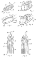
- FIG. 1 is a possible bristle carrier plate 10 shown in a perspective view obliquely from above. From its top 12 to the bottom 14 extend a number of passages 16. These have in the example shown a kidney-shaped or oval cross-section. The passages may also have a circular or any other cross section. From the bottom 14 is in the direction towards below a ring-shaped Zentri mecanicswulst 18, which extends at a small distance from the side edge of the bristle carrier plate 10 along this and is preferably formed wedge-shaped tapering towards the free end. Directly adjacent to the centering bead 18, on the underside 14 of the bristle carrier plate 10, a circumferential and along the side edge extending welding edge 19 is attached.
- the welding edge 19 can of course also be provided at any other location laterally or on the underside of the bristle carrier plate 10. In particular, it is also possible to attach the welding edge to the centering bead 18.
- FIG. 2 shows in the same representation as FIG. 1 the bristle support plate 10, which is provided by means of an AFT method with a schematically indicated bristle facing 20.
- the bristle facing 20 has a bristle bundle 22 per passage 16.
- Each of the bristle bundles 22 consists of a plurality of bristles; These are described in detail below.
- FIG. 3 shows a head portion 24 and a portion of a subsequent neck portion 26 of a toothbrush body 28.
- the head area 24 is of his in the FIG. 3 upper side 30 ago provided with a recess 32 which corresponds to the shape of the bristle carrying plate 10 and is limited by a bottom 34 substantially.
- the side wall of this recess 32 has a circumferential shoulder, which forms a welding shoulder 35.
- the back 36 of the toothbrush body 28 is located on the opposite side of the front 30 and is lying in the view shown below.
- FIG. 4 shows the bristle carrier plate 10 provided with the bristle stock 20 inserted into the recess 32. The insertion is facilitated by the Zentri mecanicswulst 18.
- the upper side 12 of the bristle carrier plate 10 is preferably aligned with the front side 30 of the toothbrush body 28.
- the bristle carrier plate 10 is firmly connected to the toothbrush body 28, preferably by means of ultrasonic welding. In this case, a weld is performed in the region of the welding edge 19 and the welding paragraph 35.
- the bristle facing 20 projects beyond the top 12.
- FIG. 4 thus shows the head area and part of the neck area of a toothbrush 28 '.
- other methods of bristle or bristle anchor anchoring can be used at this point (see, for example, method described further above).
- the bristle carrier plate 10 is preferably made of a hard plastic, for example polypropylene PP), polyamide (PA), polyester (PET), polycyclohexanedimethanoltherastalate (PCT / PCT-A (acid-modified) / PCT-G (glycol-modified)), Polyethylene (PE), polystyrene (PS), styrene-acrylonitrile (SAN), polymethyl methacrylate (PMMA), acrylic buthadiene styrene (ABS), polyoxymethylene (POM), etc.
- Polypropylene (PP) is preferably used with an E-modulus of 1000-2400 N / mm 2 , preferably 1300-1800 N / mm 2 .
- the head portion 24 and the neck portion 26 of the toothbrush body 28 is made of one of these hard plastics.
- the bristle carrier plate 10 and the toothbrush body 28 of the same hard plastic at least in the contact region of the two parts used.
- both the bristle carrier plate 10 and the toothbrush body 28 can be produced in a multi-component injection molding process.
- both the bristle carrying plate 10 and the toothbrush body 28 can each be constructed from one or more hard plastics and / or one or more soft plastics.
- Low-density polyethylene (PE-LD), high-density polyethylene (PE-HD), polyethylene (PE), rubber-elastic material such as polyurethane (PUR), thermoplastic elastomer (TPE), etc. are particularly suitable as soft plastics.
- the Shore A hardness of the soft plastic is preferably below 90.
- the passages 16 are preferably arranged in hard plastic.
- the soft plastics can be used both for the shaping of additional soft elastic cleaning elements on the bristle carrier plate 10 or on the head portion 24 are used or attached to the toothbrush body for functional or decorative purposes.
- Chemically sharpened bristles 40 as in FIG. 5 are generally known and available on the market. They are preferably made of polyester, possible subgroups are polybutylene terephthalate (PBT) or polytrimethylene terephthalate (PTT). Polyamide (PA) is preferably used if the bristles are sharpened in another way, for example mechanically or thermally. In particular by chemical means, by etching, pointed bristles 40 may have at their tip 42 an extremely thin etching thread or residual thread 44, the mass of at least in one dimension less than 0.04 mm, often smaller 0.025 mm and usually less than 0.015 mm.
- PBT polybutylene terephthalate
- PTT polytrimethylene terephthalate
- PA polyamide
- pointed bristles 40 may have at their tip 42 an extremely thin etching thread or residual thread 44, the mass of at least in one dimension less than 0.04 mm, often smaller 0.025 mm and usually less than 0.015 mm.
- the length of the pointed bristles 40 for use in a bristle machine is preferably between 14 mm and 20 mm, preferably 16-18 mm, more preferably 17 mm, with the bristles 40 tapered on one side and a blunt end on the side remote from the tip 42 46 have.
- the in the FIG. 5 A recognizable relatively large variation in the length of the sharpened bristles results from the production process of the bristles.
- the sharpened bristles 40 have a pointed portion 48 with the tip 42 and a cylindrical portion 50 with the blunt end 46.
- the diameter of the cylindrical portion 50 is 0.10 mm to 0.25 mm, preferably 0.15 mm to 0.20 mm.
- the length of the pointed portion 48 measured from the tip 42 is at least 5 mm, preferably between 7 and 12 mm, in particular between 8 mm and 11 mm.
- the taper has at the free end, at the tip 42 in the region before the beginning of the etching, after the chemical sharpening usually has a diameter of 0.015 mm to 0.025 mm, preferably 0.016 mm to 0.018 mm.
- both pointed bristles 40 as well as continuously cylindrical conventional bristles 86 may have cross-sectional areas deviating from a circular area.
- they may have triangular, rectangular, square, rhomboidal, elliptical, polygonal, star-shaped, regular n-shaped, or irregularly shaped cross-sectional areas.
- the tips 42 of the sharpened bristles 40 are preferably machined by means of a mechanical processing device, in particular a grinding wheel 52; see FIG. 7 , In this case, the pointed bristles 40 are held at least approximately in the transition region from the cylindrical portion 50 in the tapered portion 48.
- a holding element 54 may for this purpose have an approximately U-shaped cutout into which the sharpened bristles 42 are inserted and in which the bristles 40 are retained by means of a spring-loaded pressing element 56, for example, during the mechanical processing.
- the holding element 54 used is preferably an element integrated in the so-called rounding disk, which is supported by a clamping mechanism mounted outside the disk.
- the tips 42 of the bristles 40 are directed downwardly and the overhead blunt ends 46 of the bristles 40 abut against a stop plate 58. This prevents the escape of tapered bristles 40 in the direction away from the grinding wheel 52 due to the pressure exerted by the grinding wheel 52 on the tips 42 of the bristles 40. While such abrasive wheels 52 are for removing the cutting edges and rounding off the blunt ends of full length cylindrical conventional bristles 86 - see FIG.
- the tips 42 of the pointed bristles 40 between 3 seconds to 8 seconds, preferably 3.5 seconds to 6.5 seconds, especially between 4 to 6 seconds by means of the grinding wheel 52 processed, depending on Abrasiveness of the grinding wheel 52, process parameters and obtained result.
- the processing time of the sharpened bristles 40 is thus shorter than the processing time of the continuous cylindrical conventional bristles 86. Both types of bristles can be used in the same brush head and thus simultaneously processed with different process parameters.
- the grinding wheel 52 is driven in an eccentric shape, so that when viewed in the plane, it executes a stroke of 20 to 50 mm, preferably between 30 and 40 mm, in the two directions perpendicular to each other.
- the stroke of the grinding wheel 52, measured in the longitudinal direction of the bristles 40, is between 0 and 1.5 mm, preferably between 0.2 to 0.6 mm.
- the grinding wheel 52 is brought to the middle position of the tips 42 of the bristle bundle 22, after which it processes the tips between 0.3 and 3 seconds, preferably 0.5 to 1.5 seconds.
- the position of the grinding wheel 52 is adjusted by 0.1 to 1 mm, preferably 0.2 to 0.6 mm, in the direction of the pointed bristles 40, after which the driven grinding wheel 52 for another 2 to 6 seconds, preferably 3 to 5 Seconds acting on the pointed bristles 40. It has been found that reliably any possible etching threads or residual threads 44 are removed, even at bristle tips 42, which are set back as a result of the variation of the total length of the bristles 40.
- the mechanically processed pointed bristles 40 are fed to an intermediate storage in which they are brought together with already previously machined sharpened bristles 40 together.
- This intermediate storage then bristles 40 for the formation of the bristle bundles 22, compare FIG. 2 taken in groups.
- the pointed bristles 40 of the respective bundle 22 need not coincide with the aforementioned bundle for the mechanical processing of the tips 42.
- the bristle bundles 22 can be assembled from a plurality of removed groups.
- FIG. 8 shows a part of a tool 60, consisting of a block-like base body 62, also called pallet, and a funnel plate 63 of the bristle machine.
- a receiving recess 64 Through the block-like base body 62 of the tool 60 extends, in the present case in the vertical direction, a receiving recess 64.
- the cross section of this receiving recess 64 is constant over the entire length of the rectilinear receiving recess 64 in the block-like base body 62.
- a pin 66 is guided in sliding fit.
- the block-like basic body 62 with associated pins 66 is compared with one circular arc 98 FIG. 13 - filled with bundles of pointed bristles 40.
- the sliding fit between the base body 62 and the pin 66 is configured such that the tips 42 of the mechanically machined sharpened bristles 40 have a larger diameter than the tolerance range of the sliding fit. This substantial improvement step prevents jamming of the pointed bristles 40 between the pin 66 and the receiving recess 64.
- the movement of the pin 66 in the slip fit is restricted so that it is movable only in the block-like base body 62.
- the pin 66 is, for example, concave shaped to give the respective bundles of bristles 22, in the final form, a convex topography.
- the final shape of the bundles of bristles 22 is significantly influenced by the shape of the end face 68 of the pin 66.
- a concave portion of the end face 68 of the pin 66 allows the sharpened bristles 40 to bundle specifically and thereby additionally avoids jamming.
- a concave configuration instead of a concave configuration, however, other arbitrary topographies of the end face 68 of the pin 66 are possible.
- a bristle bundle 22 taken from a number of previously mechanically treated pointed bristles 40 is inserted from above with the tips 42 below into the receiving recess 64 of the block-like base body 62, at least to the extent that all bristles 40 are completely in the Receiving recess 64 are located and the bristles 40 abut with its tip 42 on the end face 68 of the pin 66.
- the topography or the profile of the bristle bundles 22 with sharpened bristles 40 is thus produced only after the mechanical processing of the tips 42.
- the funnel plate 63 is placed on the block-like base body 62 and thereon, if provided in the process, a bristle carrier plate 10 such that the bristle bundle 22 associated with this passage 16 of the bristle carrier plate 10 is aligned with the corresponding guide passage 69 in the funnel plate 63.
- the upper side 12 of the bristle carrying plate 10 comes to rest on the funnel plate 63, so that the underside 14 of the bristle carrying plate 10 is exposed upwards.
- this guide passage 69 of the funnel plate 63 also corresponds to the receiving recess 64.
- the pointed bristles 40 are moved upwards and pushed with their blunt end 46 through the funnel plate 63 and the passage 16 until an end portion 70 adjoining the blunt end 46 protrudes in the cylindrical portion 50 of the bristles 40 on the bottom 14 of the bristle plate 10.
- a heating punch 72 (or other thermal means) is lowered onto or near the bristles 40 so that the end portions 70 of the bristles 40 melt and form on the underside 14 a bristle melt coating at least partially covering the bottom 14 and thereby the bristles 40 anchored to the bristle plate 10.
- the base body 62 of the tool 60 may have a further receiving recess 64 'with further pin 66' guided therein.
- cylindrical conventional bristles 86 are inserted along their length; These come with their previously mechanically machined ends 86 'on the end face 68 of the other pin 66' to the plant, which also a topography - as described above - can be formed.
- the funnel plate 63 has a further guide passage 69 'which is aligned with the further receiving recess 64' and, on the other hand, is aligned with a passage 16 'of the bristle carrying plate 10 for conventional bristles 86.
- the further pin 66 ' is displaced to push the bundle of conventional bristles 86 through the further passage 16' of the bristle support plate 10 until the bundle of conventional bristles 86 with an end portion 70 'on the underside 14 of the bristle carrying plate 10th protrudes.
- the melting of this end portion 70 ' is carried out as described above.
- this bristle enamel coating may consist of polyester (pointed bristles 40) and polyamide (conventional bristles 86). Since these non-affine materials do not combine in the bristle melt, it is preferable to ensure that groups of bristle bundles are formed with the individual materials where the bristle melt can combine within a group.
- the similar bristle bundles are placed in this regard preferably in groups with immediate proximity. In this case, therefore, preferably the bristle bundles 22 are introduced from tapered bristles 40 or conventional bristles 86 in receiving recesses 64 or further receiving recesses 64 'which are adjacent - forming a group - arranged.
- FIG. 9 shows a way to equip a bristle carrier plate 10 with a bristle tuft having both pointed bristles 40 and conventional bristles 86.
- the base body 62 has a receiving recess 64, in which, as described above, pointed bristles 40, and close to a further receiving recess 64 ', in which conventional bristles 86 are introduced or become, compares FIG. 8 ,
- the guide passages 69 and 69 'of the funnel plate 63 associated with these receiving recesses 64 and 64' converge toward each other in the direction of the bristle carrying platelets 10 arranged on the funnel plate 63 so that they form a single common outlet for the bristles 40 and 86 at this end.
- the two passages 69 and 69 still form separate outlets, but which lie directly next to each other.
- the outlet (s) are aligned with a bristle 40 and 86 common passage 16 of the bristle support plate 10.
- the bundle 22 becomes sharpened and the bundle 22 of conventional bristles 40, 86 pushed through the common passage 10 therethrough, to the end portions thereof 70, 70 'protrude beyond the underside 14 of the bristle plate 10.
- the bristles 40, 86 are fastened to the bristle carrying plate 10.
- the provided with the bristle facing 20 bristle carrier plate 10 is, as in connection with the FIG. 4 explained, taken from the tool 60 and brought together with the toothbrush body 28 in accordance with the prior art known manner and fastened there.
- the bristles 40, 86 are guided into a mold cavity instead of through the bristle platelet 10. Plastic is then injected into this mold cavity to form the brush head and to anchor the bristles 40, 86.
- FIG. 10 shows a plan view of a portion of a feed channel 74 of a bristle 76. This is bounded below by a feed tray 78 and on both sides of mutually parallel feed walls 80.
- the pointed in the feed channel 74 or optionally cylindrical bristles 40, 86 are by means of a bar-like pusher 82 is pressed in the direction of arrow A against an outlet 84 of the feed channel 74.
- FIG. 11 shows a vertical longitudinal section through a portion of a material channel 74 'of a known AFT machine.
- cylindrical conventional bristles 86 They stand with their end, which will later form the free end of the bristle stock 20, on the material channel bottom 78 ', this corresponds to the Zunaturalgeber 78.
- the continuously constant diameter of the conventional bristles 86th is 0.15 mm to 0.25 mm. They usually have a length of 14 mm to 18 mm, preferably 16 mm.
- the distance between the cloth channel bottom 78 'and the upper edge of the profile-shaped, rectangular in cross-section pusher 82 9 mm.
- the distance between the feed channel bottom 78 and the upper edge of the pusher 82 should be greater, for example between 11 mm and 17 mm, preferably between 13 mm and 16 mm, in particular 14 mm, as in FIG FIG. 12 is indicated.
- the position of the pusher 82 in the material channel 74 'of a known Beborstungsmaschine is indicated by dashed lines.
- known AFT machines for making toothbrushes with pointed bristles 40 can be used.
- An adaptation to be made is further up in the Related to the mechanical processing of the tips 42 of the pointed bristles 40 described.
- Another is in how, in connection with the FIGS. 10 to 12 explains to arrange the pusher 82 at a greater distance to the material channel bottom 78.
- cylindrical conventional bristles 86 and pointed bristles 40 may be simultaneously processed on a single bristle machine 86.
- the bristle machine 76 in this case has both types of the above-described feed channels 74 and cloth channels 74 'and associated pushers 82.
- a knock plate 88 'of the bristle machine is shut down and thus forms only a still-standing boundary plate 88.
- the limiting plate 88 may be made larger, from the surface, so that it covers a larger part of the feed channel 74 than the known knock plate 88 'and thus substantially covers the entire feed channel 74 together with a cover plate 90 in the end region of the feed channel 74 , see also FIG.
- the knock plate 88 ' is disposed parallel to the cloth channel bottom 78' at a minimum distance corresponding to at least approximately the length of the conventional bristles 86 and provided with a vertical reciprocating motion to act on the upper ends of the conventional bristles 86 to move against the cloth channel bottom 78 ', to abut against it and thus to align the bristles 86.
- the stationary limiting plate 88 is arranged at a distance above the feed channel bottom 78, which is slightly, for example 0.1 mm to 0.5 mm, preferably 0 , 2 mm to 0.3 mm greater than the length of the pointed bristles 40.
- FIG. 13 shows by way of example in plan view a bristle 76 - in the present case, a known AFT machine - which, as described above, adapted for the processing of tapered bristles 40.
- the bristle machine 76 has two feed channels 74 or material channels 74 ', which are intended for pointed bristles 40 of different colors, for example.
- a bristle machine 76 it is possible for a bristle machine 76 to have both feed channels 74 and material channels 74 '. for pointed bristles 40 as well as for conventional bristles 86 has.
- the ratio of the number of feed channels is determined by the configuration of the bristle facing 20 of the toothbrush to be produced, or the respective bristle configuration.
- the feed channels 74 or material channels 74 ' are formed as in the FIGS. 10 to 12 shown and described above.
- the boundary plate 88 extends from the outlet 84 opposite to the direction of the arrow A seen over about 2/3 of the total length of the feed channel 74 and Stoffkanals 74 '.
- At the upstream end of the cover plate 88 is hinged to the cover plate 90, which is folded up to insert bristle supply bundles.
- the sharpened bristles 40 are delivered in bristle delivery bundles with the tip 42 of all the bristles 40 pointing in the same direction and the bristle delivery bundles having a diameter of, for example, 3 to 5 cm.
- the shape of the bristle delivery bundles is preferably configured elliptical to rectangular, due to their transport medium, an elongated cardboard packaging.
- the length of the bristle delivery bundles is from 40 mm to 60 mm, preferably from 45 mm to 55 mm with a width of 25 mm to 40 mm, preferably from 30 mm to 35 mm.
- the width of the bristle delivery bundle substantially corresponds to the width of the feed channel 74. This allows a simpler insertion of the bristle delivery bundles into the feed channel 74 without having to over-deform the fragile bristle delivery bundles.
- the bristle delivery bundles can be transported in this form easier and space-saving in an elongated cardboard packaging.
- the bristle delivery bundle laterally around the bundle a holding strip of defined length, which holds the large number of pointed bristles 40 together. Due to the defined length of the holding strip, virtually no pressure is exerted on the sharpened bristles in the bristle delivery bundle.
- the bristle delivery bundles are inserted with the tips 42 of the bristles 40 down into the feed channel 74 and cloth channel 74 ', manually advanced toward the already existing therein bristles 40, clamped by means of a manually operable carriage in the direction against the pusher 82 and then manually , preferably freed from the holding strip in the vertical direction.
- the pusher 82 is then automatically, after manual release, laterally out of the feed channel 74 and material channel 74 'extended, brought by the pressed carriage the newly inserted pointed bristles 40 in abutment with the already present in the feed channel 74 and material channel 74' pointed bristles 40 become.
- the pusher 82 is moved back to the carriage and in turn applied behind the introduced bristles 40, in order to continue to press and guide all pointed bristles 40 present in the supply channel 74 or substance channel 74 'against the outlet 84.
- a group of sharpened bristles 40 is separated from the supply. This can be done using a known boron machine in a known manner by means of a rounding disc 54 ', which may correspond to the holding element 54, see FIG. 7 , This has dashed lines indicated recesses into which the group of bristles 40 is pushed under the action of the pusher 82 into it.
- the rounding disc 54 ' is then rotated about its axis at an angle to the mechanical working station of the tips 42 of the bristles 40. In FIG. 13 If the stop plate 58 is shown, below which the pressure element 56 cooperating with the rounding disk 54 'and the driven grinding wheel 52 are located, compare this FIG. 7 , In this mechanical processing of the tips 42 of the sharpened bristles 40, the possibly present etch threads or residual threads 44 are abraded and possibly the tips 42 minimally rounded or broken.
- segments 96 In the present case, two groups of segments 96 are shown, which are independently movable along the trajectory 94.
- the segments 96 form an intermediate bearing for the bristles 40 with machined tips 42.
- the rounding disk 54 ' is further rotated in the same direction of rotation and, as soon as a recess with bristles 40 reaches the movement path 94, these bristles 40 become pushed into a corresponding segment 96 inside.
- This process, as well as the control and the structure of the segments 96 and the delivery of bundles 22 of bristles 40 of the Segments 96 on the so-called circular arc 98 is commonly known from boron machines and in particular from AFT machines.
- the circular arc 98 takes over from the relevant segment 96 a bundle 22 of bristles 40 and brings them to the tool 60 and the corresponding receiving recess 64 in the block-like base body 62, the pallet or the tool 60 of a Beborstungsmaschine; see also FIG. 8 ,
- the bristles are guided instead of through the bristle platelet 10 into a mold cavity of an injection molding tool. Plastic is then injected into this mold cavity to form the brush head and anchor the bristles.
- the bristle platelets 10 can be provided with soft-elastic cleaning elements, for example made of a soft plastic, which have been injection-molded in two or more component processes on the bristle carrier platelet 10.
- the present invention allows bristle stockings 20 to be formed in which a single bristle tuft has both pointed bristles 40 and conventional bristles 86.
- the pointed bristles 40 are processed according to the method according to the invention while the conventional bristles are processed according to the previously known method,
- care is taken that the respective bristle bundles 22 have a mixture of sharpened bristles 40 and conventional bristles 86.
- the alternative possibility should also be considered FIG. 9 and the description directed to this.
- the invention can be used for bristle fields of various products.
- manual toothbrushes electric toothbrushes with oscillating, pivoting or translational motion, vibration / sonic toothbrushes or toothbrushes with combined movements can be provided with pointed bristles.
- tongue cleaning brushes or tongue-only cleaners are also used for toothbrushes arranged.
Abstract
Description
Die vorliegende Erfindung betrifft ein Verfahren zum Herstellen von ankerlos beborsteten Zahnbürsten, bei dem ein Borstenbündel in eine Ausnahmeausnehmung eines Werkzeugs einer Beborstungsmaschine eingeführt und mittels eines in der Aufnahmeausnehmung geführten Stifts auf das dem Stift zugewandte Ende der Borsten des Borstenbündels zu deren Ausrichtung eingewirkt wird.The present invention relates to a method for producing anchorless brushed toothbrushes in which a bristle bundle is inserted into an exception recess of a tool of a bristle machine and acted upon by a guided in the receiving recess pin on the pin facing the end of the bristles of the bristle bundle to their orientation.
Beborstungsmaschinen, welche nach diesem Verfahren arbeiten, sind allgemein bekannt und werden beispielsweise von der Firma G.B. Boucherie N.V., Izegem, Belgien, als sogenannte AFT-Maschinen (Anchor Free Tufting Maschinen), hergestellt und verkauft. Eine Vorrichtung zum Befestigen von mit Borstenbüscheln versehenen Borstentragplättchen an Bürstenkörpern ist beispielsweise in Dokument
Ein weiterer Typ einer Beborstungsmaschine zur Herstellung ankerloser Borstenwaren ist aus
Ein weiterer Typ einer Beborstungsmaschine zur Herstellung ankerloser Zahnbürsten ist aus
Obwohl die Borstenverankerung der beschriebenen Verfahren unterschiedlich umgesetzt ist, kann jedoch mit der Vorbereitung, Bearbeitung und Zuführung von Borsten gleich oder ähnlich verfahren werden.Although the bristle anchorage of the described methods is implemented differently, however, the preparation, processing and feeding of bristles can be the same or similar.
Die bekannten Verfahren und die oben genannten bekannten Beborstungsmaschinen, auf welchen diese Verfahren ausgeführt werden, sind für die Bearbeitung von zylindrischen konventionellen Borsten ausgelegt, d.h. von Borsten, welche über ihre Länge einen konstanten, kreiszylinderförmigen Querschnitt aufweisen. Die durch das Abschneiden der konventionellen Borsten vom fadenartigen Ausgangsmaterial entstandenen Kanten werden auf der späteren Benützerseite der Borsten durch mechanische Bearbeitung in der Beborstungsmaschine gerundet, um die Verletzung, insbesondere des Zahnfleisches, beim Gebrauch der Zahnbürste zu verhindern. Durch die mechanische Bearbeitung nimmt das entsprechende Ende der konventionellen Borsten eine annähernd halbkugelförmige Form an. Diese bearbeiteten konventionellen Borsten werden bündelweise einem Werkzeug, einer beweglichen sogenannten Palette zugeführt, welche für jedes Bündel von konventionellen Borsten eine zylinderförmige Aufnahmeausnehmung aufweist, in welcher in Gleitpassung ein Stift geführt ist. Die Bündel von konventionellen Borsten wird mit dem mechanischen bearbeiteten Ende voraus in die Aufnahmeausnehmung eingeführt, so dass die bearbeiteten Enden am Stift anliegen. Durch Anheben des Stifts werden die konventionellen Borsten zuerst durch eine Trichterplatte und anschliessend direkt durch einen Durchlass eines Borstentragplättchens hindurch gestossen, bis ein dem abgerundeten Ende der konventionellen Borsten abgewandter Endbereich der konventionellen Borsten über die in dieser Anordnung oben liegende Unterseite des Borstentragplättchens vorsteht. Dieser Endbereich der konventionellen Borsten wird dann aufgeschmolzen, um das Borstenbündel am Borstentragplättchen zu befestigen. Dieses wird dann, beispielsweise wie im Dokument
Im IMT Verfahren gemäss
Die bekannten Verfahren und die bekannten Beborstungsmaschinen sind für die Verarbeitung von zylinderförmigen konventionellen Borsten bestimmt und ausgelegt. In jüngster Zeit ist das Bedürfnis nach Zahnbürsten mit zugespitzten Borsten gestiegen, weil derartige Borsten bei einem guten Reinigungseffekt der Zähne, insbesondere auch für die Reinigung des Interdentalbereichs, geeignet sind und das Zahnfleisch schonen.The known methods and the known boron machines are intended and designed for the processing of cylindrical conventional bristles. Recently, the need for toothbrushes with sharpened bristles has risen, because such bristles are suitable for a good cleaning effect of the teeth, especially for the cleaning of the interdental area, and protect the gums.
In der Fachwelt herrscht jedoch die Meinung, dass die bekannten Verfahren für die ankerlose Beborstung von Bürsten und die zugehörigen bekannten Beborstungsmaschinen für die Verarbeitung von derart zugespitzten Borsten technisch sehr schwierig sind. Die Anmelderin hat erste Verfahrensversuche mit zugespitzten Borsten in ankerlosen Beborstungsverfahren in der Schrift
Insbesondere scheint die mechanische Bearbeitung der Spitzen der bereits zugespitzten Borsten keinen Sinn zu machen, da ja gerade diese Spitzen erwünscht sind. Beispielhaft für die Herstellung solch chemisch zugespitzter Borsten sei an dieser Stelle die Schrift
Es ist deshalb eine Aufgabe der vorliegenden Erfindung, ein Verfahren zu schaffen, welches das ankerlose Beborsten von Zahnbürsten mit zugespitzten Borsten ermöglicht.It is therefore an object of the present invention to provide a method which allows anchorless bristling of toothbrushes with sharpened bristles.
Eine weitere Aufgabe dieser Erfindung ist es, eine Zahnbürste mit chemisch zugespitzten Borsten bereitzustellen, deren Enden eine spezielle Zuspitzung aufweisen.Another object of this invention is to provide a toothbrush with chemically sharpened bristles, the ends of which have a special taper.
Weiter ist es eine Aufgabe der vorliegenden Erfindung, eine Beborstungsmaschine für die Durchführung des erfindungsgemässen Verfahrens zu schaffen.It is a further object of the present invention to provide a bristle machine for carrying out the method according to the invention.
In Überwindung des Vorurteils, der nicht möglichen Verarbeitbarkeit von zugespitzten Borsten auf AFT-Maschinen, werden erfindungsgemäss einseitig chemisch zugespitzte Borsten, welche einen zu einer Spitze zulaufenden zugespitzten Abschnitt und einen daran anschliessenden, ein stumpfes Ende aufweisenden zylindrischen Abschnitt aufweisen, bündelweise derart in die Aufnahmeausnehmung eines Werkzeugs beziehungsweise einer Palette eingeführt, dass sich die zugespitzten Borsten in ihrer ganzen Länge in der Aufnahmeausnehmung befinden. Mittels eines Stiftes wird auf die Spitzen eingewirkt; vorzugsweise werden die zugespitzten Borsten dadurch durch eine Trichterplatte geschoben; damit ist ein gewünschtes Höhenprofil des Borstenfeldes erzielbar. Um dies zu ermöglichen, werden die Spitzen der zugespitzten Borsten vor dem Einführen in die Aufnahmeausnehmung zusätzlich mechanisch bearbeitet.In overcoming the prejudice, the non-feasible processability of pointed bristles on AFT machines, according to the invention chemically sharpened bristles having a tapered to a tip portion and a subsequent, having a blunt end cylindrical portion, bundle manner in the receiving recess a tool or a pallet introduced that the pointed Bristles are in their full length in the receiving recess. By means of a pin is acted on the tips; Preferably, the sharpened bristles are thereby pushed through a funnel plate; so that a desired height profile of the bristle field can be achieved. In order to make this possible, the tips of the sharpened bristles are additionally mechanically processed prior to insertion into the receiving recess.
Es sei ausdrücklich darauf hingewiesen, dass, ohne den Rahmen der Erfindung zu verlassen, alternativ zu 'chemisch' zugespitzten auch mit anderen Verfahren zugespitzte Borsten erfindungsgemäss der Beborstungsmaschine zugeführt werden können. Mögliche alternative Verfahren zur Zuspitzung der Borsten sind beispielsweise eine spezielle Extrusion der Borsten, welche zugespitzte Segmente erlaubt, verschiedene mechanische Bearbeitungen, thermische Verfahren oder Kombinationen davon.It should be expressly understood that, without departing from the scope of the invention, as an alternative to 'chemically' pointed and bristled with other methods pointed bristles according to the invention of the Beborstungsmaschine can be supplied. Possible alternative methods for sharpening the bristles include, for example, a special extrusion of the bristles which permits tapered segments, various mechanical processes, thermal processes or combinations thereof.
Testversuche mit dem vorbekannten AFT Verfahren mit chemisch zugespitzten Borsten haben gezeigt, dass das Vorurteil gerechtfertigt war. Chemisch zugespitzte Borsten, insbesondere im Randbereich des jeweiligen Borstenbündels, wurden zwischen dem Werkzeug, das heisst der Palette, und dem Stift eingeklemmt, was einerseits Störungen verursachte und andererseits zu einer nicht brauchbaren Beborstung führte, da die zugespitzten Borsten durch die Klemmung an der Oberfläche verletzt wurden. Im Verlauf der aufwendigen Suche nach der Ursache wurde festgestellt, dass nach allgemein bekannten Verfahren chemisch zugespitzte Borsten an der Spitze einen äusserst dünnen Ätzfaden beziehungsweise Restfaden aufweisen können. Versuche an zugespitzten Borsten haben dann gezeigt, dass mittels der bekannten mechanischen Bearbeitung der Borstenenden diese Ätzfäden beziehungsweise Restfäden beseitigt werden können. Überraschenderweise haben dann Versuche mit derartig mechanisch bearbeiteten zugespitzten Borsten gezeigt, dass durch die Beseitigung der Ätzfäden beziehungsweise Restfäden auch ein Einklemmen der Borsten zwischen dem Werkzeug und dem Stift verhindert werden kann. Die mechanische Bearbeitung führt damit zu einem definierten Abschluss bei der Spitze der chemisch zugespitzten Borsten, welcher eine problemlose Weiterverarbeitung erlaubt.Trial tests using the previously known AFT method with chemically sharpened bristles have shown that the prejudice was justified. Chemically sharpened bristles, in particular in the edge region of the respective bristle bundle, were clamped between the tool, ie the pallet, and the pin, which on the one hand caused interference and on the other hand led to unusable bristles, as the sharpened bristles were damaged by the clamping on the surface were. In the course of the extensive search for the cause, it was found that chemically sharpened bristles at the tip can have an extremely thin etching thread or residual thread according to generally known methods. Experiments on pointed bristles then have have shown that these etching threads or residual threads can be eliminated by means of the known mechanical processing of the bristle ends. Surprisingly, then experiments have shown with such mechanically machined sharpened bristles that by removing the etch threads or residual threads and pinching of the bristles between the tool and the pin can be prevented. The mechanical processing thus leads to a defined conclusion at the tip of the chemically sharpened bristles, which allows easy further processing.
In bevorzugter Weise werden die Spitzen der zugespitzten Borsten direkt in der Beborstungsmaschine mechanisch bearbeitet, um die Ätzfäden beziehungsweise Restfäden zu entfernen. Dies ermöglicht die Verwendung von chemisch zugespitzten Borsten wie sie auf dem Markt erhältlich sind. Es wäre ebenfalls möglich, die mechanische Bearbeitung von chemisch zugespitzten Borsten ausserhalb der Beborstungsmaschine vorzunehmen, um dann diese vorbereiteten zugespitzten Borsten anschliessend dem Beborstungsprozess ohne weitere Bearbeitung zuzuführen.Preferably, the tips of the sharpened bristles are mechanically machined directly in the bristle machine to remove the etch threads. This allows the use of chemically sharpened bristles as they are available in the market. It would also be possible to perform the mechanical processing of chemically sharpened bristles outside the bristle machine, and then to supply these prepared sharpened bristles to the bristle process without further processing.
Gemäss einer bevorzugten Ausführungsform des erfindungsgemässen Verfahrens werden bei der mechanischen Bearbeitung die Spitzen der Borsten, insbesondere mittels einer Schleifscheibe, geschliffen. Selbstverständlich können auch andere dem Fachmann bekannte Verfahren vorzugsweise Bearbeitungseinheiten verwendet werden. In Frage kommen beispielsweise Laser, chemische, andere mechanische oder thermische Verfahren oder Kombinationen davon.According to a preferred embodiment of the method according to the invention, the tips of the bristles, in particular by means of a grinding wheel, are ground during the mechanical processing. Of course, other methods known to those skilled in the art may preferably be used. For example, lasers, chemical, other mechanical or thermal processes or combinations thereof are possible.
In bevorzugter Weise werden Borsten verwendet, deren zugespitzter Abschnitt mindestens eine Länge von 5 mm aufweist. Vorzugsweise ist der zugespitzte Abschnitt jedoch länger und misst zwischen 7 und 12 mm, insbesondere zwischen 8 und 11 mm. Derartige zugespitzte Borsten gewährleisten bei einem guten Reinigungseffekt eine besonders schonende Behandlung des Zahnfleisches und eine gute Reinigung der Interdentalräume.Preferably, bristles are used whose pointed portion has at least a length of 5 mm. Preferably, however, the sharpened portion is longer and measures between 7 and 12 mm, in particular between 8 and 11 mm. Such sharpened bristles ensure, with a good cleaning effect, a particularly gentle treatment of the gums and a good cleaning of the interdental spaces.
In besonders bevorzugter Weise werden die zugespitzten Borsten, im Gegensatz zu den durchwegs zylindrischen konventionellen Borsten, während der mechanischen Bearbeitung der Spitzen wenigstens annähernd im Übergangsbereich vom zylindrischen in den zugespitzten Abschnitt gehalten beziehungsweise geklemmt. Dadurch wird einerseits die Gefahr des Verschiebens von zugespitzten Borsten auf Grund einer auf die Borsten in Richtung zum stumpfen Ende wirkenden Kraft vermindert und andererseits werden die zugespitzten Borsten während der mechanischen Bearbeitung stabilisiert. Wird zur Durchführung dieser bevorzugten Ausführungsform des erfindungsgemässen Verfahrens eine verbesserte Beborstungsmaschine verwendet, erfolgt dieses Halten der zugespitzten Borsten vorzugsweise mittels einer Verrundungsscheibe, beziehungsweise mittels zur Verrundungsscheibe zugehörigen Elementen der Beborstungsmaschine und einem damit zusammenwirkenden Andrückelement.In a particularly preferred manner, the sharpened bristles, in contrast to the consistently cylindrical conventional bristles, are held or clamped at least approximately in the transition region from the cylindrical to the pointed section during the mechanical machining of the tips. As a result, on the one hand, the risk of displacement of sharpened bristles due to a force acting on the bristles in the direction of the blunt end is reduced and, on the other hand, the sharpened bristles are stabilized during mechanical processing. If an improved Beborstungsmaschine used to carry out this preferred embodiment of the inventive method, this holding the tapered bristles is preferably carried out by means of a rounding disc, or by means of the rounding plate associated elements of the Beborstungsmaschine and a cooperating pressure element.
Auf einer erfindungsgemässen Beborstungsmaschine können gleichzeitig zugespitzte Borsten gemäss dem erfindungsgemässen Verfahren und durchgängig zylindrische konventionelle Borsten verarbeitet und im gleichen Bürstenkopf verankert werden. Hierbei werden die Borsten jedoch in separaten Zuführkanälen für die zugespitzten Borsten und separaten Zuführkanälen für die konventionellen Borsten in die Maschine eingebracht.On a bristle machine according to the invention pointed bristles according to the method according to the invention and cylindrical conventional bristles can be simultaneously processed and anchored in the same brush head. In this case, however, the bristles are in separate feed channels for the sharpened Bristles and separate feed channels for the conventional bristles introduced into the machine.
In weiter bevorzugter Weise werden die zugespitzten Borsten bei der mechanischen Bearbeitung der Spitzen mittels einer mit dem stumpfen Ende der zugespitzten Borsten zusammenwirkenden Anschlagplatte ausgerichtet gehalten. Diese gewährleistet, dass die Spitzen sämtlicher zugespitzten Borsten mechanisch bearbeitet werden und nicht ausweichen können.More preferably, the pointed bristles are held aligned in the machining of the tips by means of a cooperating with the blunt end of the pointed bristles stop plate. This ensures that the tips of all sharpened bristles are mechanically processed and can not escape.
Bevorzugt ist die Gleitpassung zwischen Werkzeug und Stift derart ausgestaltet, dass die Spitzen der mechanisch bearbeiteten zugespitzten Borsten einen grösseren Durchmesser aufweisen als der Toleranzbereich der Gleitpassung.Preferably, the sliding fit between the tool and the pin is configured such that the tips of the mechanically processed sharpened bristles have a larger diameter than the tolerance range of the sliding fit.
Weiter bevorzugt weist der Stift an seiner oben liegenden, im Werkzeug befindenden Stirnseite einen konkaven Bereich auf. Dies vermittelt dem Borstenbündel eine konvexe Topographie, in welcher die Spitzen der mechanisch bearbeiteten zugespitzten Borsten liegen.More preferably, the pin on its overhead, located in the tool end face on a concave area. This gives the bundle of bristles a convex topography in which are the tips of the machined sharpened bristles.
Am Borstenbündel wird in bevorzugter Weise erst nach dem mechanischen Bearbeiten der Borsten eine Topographie erzeugt.The bristle bundle preferably produces a topography only after the mechanical processing of the bristles.
Bei einer weiteren besonders bevorzugten Ausbildungsform des erfindungsgemässen Verfahrens werden die zugespitzten Borsten vor der mechanischen Bearbeitung der Spitzen, mit der Spitze nach unten gerichtet, in einen Zuführkanal der Beborstungsmaschine eingelegt und im Zuführkanal mittels eines Drückers in Richtung gegen einen Auslass des Zuführkanals gedrückt, wobei der Drücker auf den zylindrischen Abschnitt der zugespitzten Borsten einwirkt.In a further particularly preferred embodiment of the inventive method, the pointed bristles are placed before the mechanical processing of the tips, directed with the tip down, in a feed channel of the bristle machine and pressed in the feed channel by means of a pusher in the direction against an outlet of the feed channel, wherein the Pusher acts on the cylindrical portion of the sharpened bristles.
Dadurch wird eine besonders einfache Handhabung der zugespitzten Borsten erreicht, wobei die Erzeugung einer Kraft durch die Einwirkung des Drückers in Richtung auf das stumpfe Ende der zugespitzten Borsten vermieden wird. Die zugespitzten Borsten bleiben dabei mit ihrer Spitze am Boden des Zuführkanals anliegend oder wenigstens annähernd anliegend und ein Bewegen von Borsten vom Boden des Zuführkanals weg wird vermieden.As a result, a particularly simple handling of the sharpened bristles is achieved, wherein the generation of a force by the action of the pusher in the direction of the blunt end of the sharpened bristles is avoided. The pointed bristles remain with their tip at the bottom of the feed channel adjacent or at least approximately fitting and moving bristles away from the bottom of the feed channel is avoided.
Bei der Durchführung des erfindungsgemässen Verfahrens auf einer angepassten Beborstungsmaschine dient der angepasste Stoffkanal als Zuführkanal. Die Beborstungsmaschine kann gleichzeitig über Stoffkanäle für durchgängig zylindrische konventionelle Borsten und angepasste Zuführkanäle für zugespitzte Borsten verfügen.When carrying out the method according to the invention on an adapted bristling machine, the adapted material channel serves as a feed channel. The bristle machine can simultaneously have fabric channels for consistently cylindrical conventional bristles and adapted feed channels for sharpened bristles.
In einer weiter bevorzugten Ausführungsform des erfindungsgemässen Verfahrens werden die zugespitzten Borsten mittels einer mit dem stumpfen Ende der Borsten zusammenwirkenden Begrenzungsplatte im Zuführkanal gehalten. Diese verhindert zusammen mit der angepassten Anordnung des Drückers, der auf den zylindrischen Teil der zugespitzten Borsten einwirkt, ein Anheben der zugespitzten Borsten vom Boden des Zuführkanals weg. Bei der Verwendung einer bekannten Beborstungsmaschine wird als Begrenzungsplatte in bevorzugter Weise die Klopfplatte verwendet, wobei diese jedoch stillgelegt ist. Die bei der Verarbeitung von zylindrischen konventionellen Borsten gängige Klopfbewegung bleibt somit aus.In a further preferred embodiment of the method according to the invention, the sharpened bristles are held in the feed channel by means of a limiting plate cooperating with the blunt end of the bristles. This, together with the mated arrangement of the pusher acting on the cylindrical portion of the pointed bristles, prevents lifting of the pointed bristles away from the bottom of the feed channel. When using a known Beborstungsmaschine is used as a limiting plate in a preferred manner, the knock plate, but this is shut down. The usual knocking motion during the processing of cylindrical conventional bristles thus remains.
In bevorzugter Weise wird auf dem Werkzeug ein mindestens einen Durchlass aufweisendes Borstentragplättchen angeordnet, und die zugespitzten Borsten des Borstenbündels werden mittels des Stifts derart durch den Durchlass gestossen, dass die zugespitzten Borsten mit einem das stumpfe Ende aufweisenden Endabschnitt des zylindrischen Abschnitts über die oben liegende Unterseite des Borstentragplättchens vorstehen. Diese Endabschnitte der Borsten werden dann aufgeschmolzen, um die zugespitzten Borsten am Borstentragplättchen zu befestigen. Gegebenenfalls kann unmittelbar auf dem Werkzeug eine Trichterplatte angeordnet sein, auf welcher das Borstentragplättchen angeordnet wird. Die Trichterplatte weist wenigstens einen Führungsdurchlass für die zugespitzten Borsten auf, wobei dieser, vom Werkzeug her gesehen, trichterartig verjüngt ausgeformt sein kann. Alternativ und weniger bevorzugt entfällt dieser Schritt, falls kein Borstentragplättchen im Verfahren integriert ist (beispielsweise IMT).Preferably, a bristle carrying plate having at least one passage is arranged on the tool, and the sharpened bristles of the bristle bundle are so moved through the pin by means of the pin Passage pushed that the pointed bristles project with a blunt end end portion of the cylindrical portion on the upper side of the underside of the Bristestentragplättchens. These end portions of the bristles are then fused to secure the sharpened bristles to the bristle support plate. Optionally, a funnel plate can be arranged directly on the tool, on which the bristle carrier plate is arranged. The funnel plate has at least one guide passage for the sharpened bristles, wherein this, seen from the tool, can be formed like a funnel-like tapered. Alternatively, and less preferably, this step is omitted if no bristle support plate is integrated in the process (eg, IMT).
Weiter bevorzugt werden in eine weitere Aufnahmeausnehmung des Werkzeugs vorgängig mechanisch bearbeitete, über ihre Länge ansonsten zylindrische, konventionelle Borsten eingeführt. Mittels eines in dieser Aufnahmeausnehmung geführten weiteren Stifts wird auf die bearbeiteten Enden der konventionellen Borsten zu deren Ausrichtung eingewirkt. Bei entsprechend geformter Stirnseite kann dem Bündel aus konventionellen Borsten eine Topographie vermittelt werden.More preferably, previously machined, over their length otherwise cylindrical, conventional bristles are introduced into a further receiving recess of the tool previously. By means of a guided in this receiving recess further pin is acted on the processed ends of the conventional bristles to their orientation. With a correspondingly shaped end face, the bundle of conventional bristles can be given a topography.
Unter Topographie wird, im Zusammenhang mit der vorliegenden Erfindung, eine durch die Spitzen der zugespitzten Borsten beziehungsweise die betreffenden Enden der konventionellen Borsten definierte Fläche verstanden, welche dreidimensional geformt ist oder eben sein kann, jedoch dann nicht rechtwinklig zur Längsrichtung des betreffend Borstenbündels verläuft.By topography is meant, in the context of the present invention, a surface defined by the tips of the pointed bristles or the respective ends of the conventional bristles, which is three-dimensionally shaped or may be flat, but then does not run at right angles to the longitudinal direction of the bristle bundle concerned.
In bevorzugter Weise werden - mit gleich ausgebildeten Werkzeugen - die Spitzen der zugespitzten Borsten weniger lang mechanisch bearbeitet als die Enden der konventionellen Borsten.Preferably, with the same tools, the tips of the sharpened bristles are less mechanically machined than the ends of the conventional bristles.
Werden in dicht beieinander angeordnete Aufnahmeausnehmungen (nur) zugespitzte Borsten und in dicht beieinander angeordnete weitere Aufnahmeausnehmungen (nur) konventionelle Borsten eingeführt, kann ein besonders sicherer Halt an einem Borstentragplättchen durch Aufschmelzen der Endabschnitte der Borsten selbst dann erzielt werden, wenn die konventionellen und die zugespitzten Borsten aus nicht affinen Kunststoffen hergestellt sind.If (only) pointed bristles are arranged in closely spaced receiving recesses and conventional bristles are arranged in closely spaced further receiving recesses, a particularly secure hold on a bristle carrying plate can be achieved by melting the end portions of the bristles even if the conventional and the sharpened Bristles are made of non-affine plastics.
Mit dem erfindungsgemässen Verfahren lassen sich auch ankerlos beborstete Zahnbürsten herstellen, bei welchen ein Borstenbüschel sowohl zugespitzte Borsten als auch konventionelle Borsten aufweist. Dazu können die zugespitzten Borsten in eine Aufnahmeausnehmung und die konventionellen Borsten in eine weitere Aufnahmeausnehmung des Werkzeugs eingeführt werden. Bevorzugt liegen diese Aufnahmeausnehmungen unmittelbar neben einander. Beim Stossen dieser Borstenbündel mittels der Stifte können die Borsten, vorzugsweise mittels einer Trichterplatte, zu einem gemeinsamen Durchlass des Borstentragplättchens geleitet werden.The method according to the invention also makes it possible to produce anchorless bristled toothbrushes in which a bristle tuft has both pointed bristles and conventional bristles. For this purpose, the sharpened bristles can be inserted into a receiving recess and the conventional bristles in a further receiving recess of the tool. Preferably, these receiving recesses lie directly next to each other. When these bundles of bristles are pushed by means of the pins, the bristles can be conducted, preferably by means of a funnel plate, to a common passage of the bristle carrying plate.
Das Borstentragplättchen wird nachfolgend, wie bekannt, am Kopf eines Zahnbürstenkörpers befestigt.The bristle carrier plate is subsequently attached to the head of a toothbrush body, as is known.
Mittels des erfindungsgemässen Verfahrens können Bündel von zugespitzten Borsten auch direkt am Kopf des Zahnbürstenkörpers befestigt werden, indem an diesem entsprechende Durchlässe ausgeformt sind.By means of the method according to the invention, bundles of sharpened bristles can also be fastened directly to the head of the toothbrush body by forming corresponding passages on the latter.
Für die Durchführung des erfindungsgemässen Verfahrens wird bevorzugt eine bekannte Beborstungsmaschine verwendet, wobei diese, wie in den betreffenden Ansprüchen angegeben, für die Verarbeitung von zugespitzten Borsten unterschiedlich ausgebildet ist beziehungsweise betrieben wird.For carrying out the method according to the invention, a known boron machine is preferably used, whereby, as indicated in the respective claims, it is designed or operated differently for the processing of sharpened bristles.
Das erfindungsgemässe Verfahren wird insbesondere für die Herstellung elektrischer und manueller Zahnbürsten eingesetzt. Das Verfahren kann natürlich generell für Bürstenware mit zugespitzten Filamenten eingesetzt werden, insbesondere auch für Bürstenware in der Kosmetik-, Körperpflege- und Medizinalindustrie.The inventive method is used in particular for the production of electric and manual toothbrushes. Of course, the method can generally be used for brushed products with pointed filaments, in particular for brushware in the cosmetics, personal care and medical industries.
Neben den erfindungsgemäss bearbeiteten zugespitzten Borsten kann die Zahnbürste auch über durchgängig zylindrische konventionelle Borsten und/oder gummielastische Reinigungselemente aus Weichmaterial verfügen.In addition to the sharpened bristles machined in accordance with the invention, the toothbrush may also have continuous cylindrical conventional bristles and / or rubber-elastic cleaning elements made of soft material.
Die Erfindung wird anhand eines in der Zeichnung dargestellten Ausführungsbeispiels näher beschrieben. Es zeigen rein schematisch:
- Fig. 1
- in perspektivischer Sicht ein Borstentragplättchen;
- Fig. 2
- ebenfalls in perspektivischer Sicht das Borstentragplättchen, versehen mit einem Borstenfeld aus mindestens teilweise zugespitzten Borsten;
- Fig. 3
- auch in perspektivischer Sicht einen Kopfbereich und einen Teil eines Halsbereichs eines Zahnbürstenkörpers mit einer Ausnehmung im Kopfbereich;
- Fig. 4
- in perspektivischer Sicht den Zahnbürstenkörper gemäss
Figur 3 mit in die Ausnehmung eingesetztem beborstetem Borstentragplättchen gemässFigur 2 ; - Fig. 5
- in Ansicht ein Bündel von chemisch zugespitzten Borsten mit Ätzfäden beziehungsweise Restfäden an der Spitze;
- Fig. 6
- ebenfalls in Ansicht ein Bündel chemisch zugespitzter Borsten, wobei die Spitzen mechanisch bearbeitet sind;
- Fig. 7
- ein schematisch dargestelltes Bündel zugespitzter Borsten bei der mechanischen Bearbeitung der Spitzen;
- Fig. 8
- einen Schnitt durch ein Werkzeug mit einer Aufnahmeausnehmung für die zugespitzten Borsten und einer weiteren Aufnahmeausnehmung für konventionelle Borsten, einem in der Aufnahmeausnehmung geführten Stift und einem in der weiteren Aufnahmeausnehmung geführten weiteren Stift für das Bewegen und Ausrichten der Borsten, einem auf einer Trichterplatte angeordneten Borstentragplättchen und einem Heizstempel;
- Fig. 9
- in gleicher Darstellung wie
Figur 8 das Werkzeug mit den Aufnahmeausnehmungen und den Stiften, dem auf der Trichterplatte angeordneten Borstentragplättchen und dem Heizstempel, wobei die Trichterplatte die zugespitzten und die konventionellen Borsten zu einem gemeinsamen Durchlass des Borstenträgerplättchens leitet. - Fig.10
- in Draufsicht einen Zuführkanal einer Beborstungsmaschine mit darin angeordneten zugespitzten oder konventionellen Borsten und einem auf die Borsten einwirkenden Drücker;
- Fig. 11
- einen Längsschnitt durch einen Abschnitt eines Stoffkanals einer Beborstungsmaschine mit im Stoffkanal angeordneten zylinderförmigen konventionellen Borsten und dem Drücker;
- Fig. 12
- in gleicher Darstellung wie
Figur 11 den Abschnitt des Zuführkanals mit darin angeordneten zugespitzten Borsten und dem vom Boden weiter weg versetzten Drücker; - Fig. 13
- in Draufsicht eine für die Durchführung des erfindungsgemässen Verfahrens angepasste AFT-Maschine; und
- Fig. 14
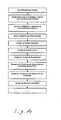
- ein Ablaufdiagramm mit Schritten des erfindungsgemässen Verfahrens.
- Fig. 1
- in perspective view, a bristle carrying plate;
- Fig. 2
- also in a perspective view of the bristle carrying plate, provided with a bristle field of at least partially sharpened bristles;
- Fig. 3
- also in a perspective view, a head region and a part of a neck region of a toothbrush body with a recess in the head region;
- Fig. 4
- in a perspective view according to the toothbrush body
FIG. 3 with bristle tufts inserted into the recess according toFIG. 2 ; - Fig. 5
- in view a bundle of chemically sharpened bristles with etch threads or residual filaments at the tip;
- Fig. 6
- also in view a bundle of chemically sharpened bristles with the tips machined;
- Fig. 7
- a schematically illustrated bundle of pointed bristles in the machining of the tips;
- Fig. 8
- a section through a tool having a receiving recess for the sharpened bristles and a further receiving recess for conventional bristles, a guided in the receiving recess pin and a guided in the other receiving recess further pin for moving and aligning the bristles, arranged on a funnel plate bristle support plates and a heating stamp;
- Fig. 9
- in the same representation as
FIG. 8 the tool having the receiving recesses and the pins, the bristle supporting plates arranged on the funnel plate and the heating punch, wherein the funnel plate directs the sharpened and the conventional bristles to a common passage of the bristle carrier plate. - Figure 10
- a top view of a feed channel of a bristle machine with pointed or conventional bristles disposed therein and a pusher acting on the bristles;
- Fig. 11
- a longitudinal section through a portion of a material channel of a Beborstungsmaschine arranged in the fabric channel cylindrical conventional bristles and the pusher;
- Fig. 12
- in the same representation as
FIG. 11 the portion of the feed channel with pointed bristles disposed therein and the pusher offset further away from the bottom; - Fig. 13
- in plan view adapted for the implementation of the inventive method AFT machine; and
- Fig. 14
- a flowchart with steps of the inventive method.
In
Das Borstentragplättchen 10 ist vorzugsweise aus einem Hart-Kunststoff gefertigt, beispielsweise Polypropylen PP), Polyamid (PA), Polyester (PET), Polycyclohexandimethanoltherastalat (PCT/PCT-A(säuremodifiziert)/PCT-G(glykolmodifziert)), Polyethylen (PE), Polystyrol (PS), Styrolacrylnitril (SAN),Polymethylmethacrylat (PMMA), Acrylbuthadienystyrol (ABS), Polyoxymethylen (POM), usw. gefertigt. In bevorzugter Weise wird Polypropylen (PP) verwendet mit einem E-Modul von 1000 - 2400 N/mm2, vorzugsweise 1300 bis 1800 N/mm2 . The
Im gezeigten Beispiel ist auch der Kopfbereich 24 und der Halsbereich 26 des Zahnbürstenkörpers 28 aus einem dieser Hart-Kunststoffe gefertigt. In bevorzugter Weise wird für das Borstentragplättchen 10 und den Zahnbürstenkörper 28 derselbe Hart-Kunststoff, wenigstens im Kontaktbereich der beiden Teile, verwendet.In the example shown, the
Der Vollständigkeit halber sei hier jedoch erwähnt, dass sowohl das Borstentragplättchen 10 als auch der Zahnbürstenkörper 28 im Mehrkomponenten-Spritzgiessverfahren hergestellt sein können. Dabei können sowohl das Borstentragplättchen 10 als auch der Zahnbürstenkörper 28 jeweils aus einem oder mehreren Hart-Kunststoffen und /oder aus einem oder mehreren Weich-Kunststoffen aufgebaut sein. Als Weich-Kunststoffe eignen sich insbesondere low density Polyethylen (PE-LD), high density Polyethylen (PE-HD), Polyethylen (PE), gummielastischer Werkstoff wie Polyurethan (PUR), thermoplastisches Elastomer (TPE) usw. Vorzugsweise wird ein thermoplastisches Elastomer (TPE) verwendet. Die Shore A Härte des Weich-Kunststoffes liegt vorzugsweise unter 90. Besteht das Borstentragplättchen 10 aus einem oder mehreren Hart-Kunstoffen und einem oder mehreren Weich-Kunststoffen, sind die Durchlässe 16 vorzugsweise im Hart-Kunststoff angeordnet. Die Weich-Kunststoffe können sowohl für die Ausformung von zusätzlichen weichelastischen Reinigungselementen am Borstentragplättchen 10 oder am Kopfbereich 24 genutzt werden oder am Zahnbürstenkörper für funktionelle oder dekorative Zwecke angebracht werden.However, for the sake of completeness, it should be mentioned here that both the
Chemisch zugespitzte Borsten 40, wie sie in
Es können auch zweiseitig zugespitzte Borsten, die die doppelte Länge der beschriebenen einseitig zugespitzten Borsten haben, verwendet werden, nur müssen diese, bevor sie in der Beborstungsmaschine verarbeitet werden können, auf die obgenannten Masse für einseitig zugespitzte Borsten mittig durchgeschnitten werden.It is also possible to use bilaterally sharpened bristles which are twice the length of the one-sided sharpened bristles described, but only before they can be processed in the bristle machine, they must be cut centrally on the aforementioned composition for unilaterally tapered bristles.
Die zugespitzten Borsten 40 weisen einen zugespitzten Abschnitt 48 mit der Spitze 42 und einem zylinderförmigen Abschnitt 50 mit dem stumpfen Ende 46 auf. Der Durchmesser des zylinderförmigen Abschnitts 50 beträgt 0,10 mm bis 0,25 mm, vorzugsweise 0,15 mm bis 0,20 mm. Die Länge des zugespitzten Abschnitts 48 von der Spitze 42 her gemessen beträgt mindestens 5 mm, vorzugsweise zwischen 7 und 12 mm, insbesondere zwischen 8 mm und 11 mm. Die Zuspitzung hat am freien Ende, an der Spitze 42 im Bereich vor dem Beginn des Ätzfadens, nach dem chemischen Zuspitzen üblicherweise einen Durchmesser von 0,015 mm bis 0,025 mm, vorzugsweise 0,016 mm bis 0,018 mm.The sharpened bristles 40 have a pointed
Selbstverständlich können sowohl zugespitzten Borsten 40 als auch durchgehend zylindrische konventionelle Borsten 86 von einer Kreisfläche abweichende Querschnittsflächen aufweisen. Beispielsweise können sie dreieckige, rechteckige, quadratische, rhomboide, elliptische, mehreckige, sternförmige, regelmäßig n-eckige oder unregelmäßig geformte Querschnittsflächen aufweisen.Of course, both pointed
Um allfällige am zugespitzten Ende 42 der Borsten 40 vorhandene Ätzfäden beziehungsweise Restfäden 44 zu entfernen, werden alle zugespitzten Borsten 34 bündelweise mechanisch bearbeitet. Nach der mechanischen Bearbeitung hat die Zuspitzung an der Spitze 42 einen Durchmesser von etwa 0,016 mm bis 0,035 mm, vorzugsweise 0,019 mm bis 0,029 mm.
Die Spitzen 42 der zugespitzten Borsten 40 werden vorzugsweise mittels einer Vorrichtung zur mechanischen Bearbeitung, insbesondere einer Schleifscheibe 52, bearbeitet; siehe dazu
Die Schleifscheibe 52 wird exzenterförmig angetrieben, so dass sie, in der Ebene gesehen, in den zwei rechtwinklig zueinander stehenden Richtungen einen Hub von 20 bis 50 mm, vorzugsweise zwischen 30 und 40 mm ausführt. Der Hub der Schleifscheibe 52, in Längsrichtung der Borsten 40 gemessen, beträgt zwischen 0 und 1,5 mm, vorzugsweise zwischen 0.2 bis 0.6 mm. In bevorzugter Weise wird die Schleifscheibe 52 an die mittlere Position der Spitzen 42 des Borstenbündels 22 gebracht, wonach sie die Spitzen zwischen 0.3 und 3 Sekunden, vorzugsweise 0,5 bis 1.5 Sekunden, bearbeitet. Anschliessend wird die Lage der Schleifscheibe 52 um 0,1 bis 1 mm, vorzugsweise 0,2 bis 0,6 mm, in Richtung in die zugespitzten Borsten 40 hinein verstellt, wonach die angetriebene Schleifscheibe 52 weitere 2 bis 6 Sekunden, vorzugsweise 3 bis 5 Sekunden, auf die zugespitzten Borsten 40 einwirkt. Es hat sich gezeigt, dass dabei zuverlässig allfällige Ätzfäden beziehungsweise Restfäden 44 beseitigt werden, auch an Borstenspitzen 42, welche in Folge der Variation der Gesamtlänge der Borsten 40 zurückversetzt sind. Da die zugespitzten Borsten 40 in Folge ihrer Zuspitzung und der Anordnung der Haltevorrichtung bestehend aus dem Halteelement 54 und dem federbelasteten Andrückelement 56 im Bereich ihrer Zuspitzung äusserst flexibel sind, besteht auch keine Gefahr, dass sie zu stark gekürzt werden, so dass keine "Spitzen" mehr vorhanden wären.The grinding
In bevorzugter Weise werden die mechanisch bearbeiteten zugespitzten Borsten 40 einem Zwischenlager zugeführt, in welchem sie mit bereits vorgängig mechanisch bearbeiteten zugespitzten Borsten 40 zusammen gebracht werden. Diesem Zwischenlager werden dann die Borsten 40 für die Bildung der Borstenbündel 22, vergleiche
Ebenso können die Borstenbündel 22 aus mehreren entnommenen Gruppen zusammengestellt werden. Insbesondere ist es auch möglich durchgehend zylindrische konventionelle Borsten 86 mit zugespitzten Borsten 40 in einem Bündel zu mischen.Likewise, the bristle bundles 22 can be assembled from a plurality of removed groups. In particular, it is also possible to mix continuous cylindrical
Im Verfahrensablauf wird der blockartige Grundkörper 62 mit zugehörigen Stiften 66 vom einen Kreisbogen 98 her - vergleiche
Die Gleitpassung zwischen Grundkörper 62 und Stift 66 ist derart ausgestaltet, dass die Spitzen 42 der mechanisch bearbeiteten zugespitzten Borsten 40 einen grösseren Durchmesser aufweisen als der Toleranzbereich der Gleitpassung. Dieser wesentliche Verbesserungsschritt verhindert das Verklemmen der zugespitzten Borsten 40 zwischen dem Stift 66 und der Aufnahmeausnehmung 64. Die Bewegung des Stifts 66 in der Gleitpassung ist eingeschränkt, so dass er nur im blockartigen Grundkörper 62 beweglich ist.The sliding fit between the
An seiner oben liegenden, im Grundkörper 62 befindenden Stirnseite 68, an welcher die Spitzen 42 der zugespitzten Borsten 40 anliegen, ist der Stift 66 beispielsweise konkav geformt, um dem betreffenden Borstenbündel 22, in der Endform, eine konvexe Topographie zu vermitteln. Die Endform der Borstenbündel 22 wird durch die Form der Stirnseite 68 des Stifts 66 massgeblich beeinflusst. Ein konkaver Bereich der Stirnseite 68 des Stiftes 66 erlaubt es, die zugespitzten Borsten 40 speziell zu bündeln und vermeidet dadurch zusätzlich das Verklemmen. Anstelle einer konkaven Ausgestaltung sind jedoch auch andere beliebige Topographien der Stirnseite 68 des Stiftes 66 möglich.At its upper, located in the base 62 end face 68, against which the
Ein dem Zwischenlager entnommenes Borstenbündel 22 aus einer Anzahl vorgängig mechanisch bearbeiteten zugespitzten Borsten 40 wird von oben mit den unten liegenden Spitzen 42 voraus, in die Aufnahmeausnehmung 64 des blockartigen Grundkörpers 62 eingeführt, mindestens soweit, dass sich alle Borsten 40 komplett in der Aufnahmeausnehmung 64 befinden und die Borsten 40 mit ihrer Spitze 42 an der Stirnseite 68 des Stifts 66 anliegen. Die Topographie oder das Profil der Borstenbündel 22 mit zugespitzten Borsten 40 wird somit erst nach dem mechanischen Bearbeiten der Spitzen 42 erzeugt.A bristle
Anschliessend wird die Trichterplatte 63 auf den blockartigen Grundkörper 62 und darauf, falls im Verfahren vorgesehen, ein Borstentragplättchen 10 derart abgelegt, dass der diesem Borstenbündel 22 zugeordnete Durchlass 16 des Borstentragplättchens 10 mit dem entsprechenden Führungsdurchlass 69 in der Trichterplatte 63 fluchtet. Dabei kommt die Oberseite 12 des Borstentragplättchens 10 auf der Trichterplatte 63 zur Anlage, so dass die Unterseite 14 des Borstentragplättchens 10 nach oben frei liegt. Der Vollständigkeit halber sie erwähnt, dass dieser Führungsdurchlass 69 der Trichterplatte 63 andererseits auch mit der Aufnahmeausnehmung 64 korrespondiert. Durch Bewegung des Stifts 66 in Richtung nach oben auf das Borstentragplättchen 10 zu werden die zugespitzten Borsten 40 nach aufwärts bewegt und mit ihrem stumpfen Ende 46 voraus durch die Trichterplatte 63 und den Durchlass 16 hindurch gestossen, bis ein an das stumpfe Ende 46 anschliessender Endabschnitt 70 im zylinderförmigen Abschnitts 50 der Borsten 40 über die Unterseite 14 des Borstenplättchens 10 vorsteht. Anschliessend wird ein Heizstempel 72 (oder ein anderes thermisches Mittel) auf die Borsten 40 oder in deren Nähe abgesenkt, so dass die Endabschnitte 70 der Borsten 40 schmelzen und auf der Unterseite 14 einen, die Unterseite 14 mindestens teilweise bedeckenden Borstenschmelzebelag bilden und dadurch die Borsten 40 am Borstenplättchen 10 verankert.Subsequently, the funnel plate 63 is placed on the block-
In gleicher Art und Weise wie oben beschrieben, kann der Grundkörper 62 des Werkzeugs 60 eine weitere Aufnahmeausnehmung 64' mit darin geführtem weiterem Stift 66' aufweisen. In diese werden, gleich wie im Zusammenhang mit zugespitzten Borsten 40 beschrieben, über ihre Länge zylindrische konventionelle Borsten 86 eingeführt; diese kommen mit ihrem vorgängig mechanisch bearbeiteten Enden 86' an der Stirnseite 68 des weiteren Stifts 66' zur Anlage, wobei ebenfalls eine Topographie - wie oben beschrieben - gebildet werden kann. Die Trichterplatte 63 weist einen, mit der weiteren Aufnahmeausnehmung 64' fluchtenden weiteren Führungsdurchlass 69' auf, welcher andererseits mit einem Durchlass 16' des Borstentragplättchens 10 für konventionelle Borsten 86 fluchtet.In the same way as described above, the
Gleichzeitig mit dem Stift 66 wird der weitere Stift 66' verschoben, um das Bündel konventionelle Borsten 86 durch den weiteren Durchlass 16' des Borstentragplättchens 10 hindurch zu stossen, bis das Bündel konventionelle Borsten 86 mit einem Endabschnitt 70' über die Unterseite 14 des Borstentragplättchens 10 vorsteht. Auch das Aufschmelzen dieses Endabschnitts 70' erfolgt wie weiter oben beschrieben.Simultaneously with the
Falls verschiedene Kunststoffe für die Herstellung der Borsten 40, 86 verwendet wurden, entsteht folglich auch ein Borstenschmelzebelag aus den entsprechenden Kunststoffen. Insbesondere kann dieser Borstenschmelzbelag aus Polyester (zugespitzte Borsten 40) und Polyamid (konventionelle Borsten 86) bestehen. Da sich diese - nicht affinen - Materialien in der Borstenschmelze nicht verbinden, ist bevorzugt darauf zu achten, dass mit den einzelnen Materialien Gruppen von Borstenbündel gebildet werden, bei welchen sich die Borstenschmelze innerhalb einer Gruppe verbinden kann. Die gleichartigen Borstenbündel werden diesbezüglich vorzugsweise in Gruppen mit unmittelbarer Nähe platziert. In diesem Fall werden somit vorzugsweise die Borstenbündel 22 aus zugespitzten Borsten 40 beziehungsweise konventionellen Borsten 86 in Aufnahmeausnehmungen 64 beziehungsweise weitere Aufnahmeausnehmungen 64' eingeführt, welche benachbart - eine Gruppe bildend - angeordnet sind.If various plastics were used for the production of the
Auf entsprechende Art und Weise ist es möglich, mehrere einzelne Bündel 22 von Borsten 80, 86 aus verschiedenen Aufnahmeausnehmungen 64 mittels der Trichterplatte 63 zu vereinen und somit zusammen ein Borstenbüschel in einem gemeinsamen Durchlass 16 zu bilden. Auf dieselbe Art und Weise ist es auch möglich, Bündel 22 von Borsten 40 oder 86 gleicher Art einem gemeinsamen Durchlass 16 zuzuführen.In a corresponding manner, it is possible to combine a plurality of
Das mit dem Borstenbesatz 20 versehene Borstentragplättchen 10 wird, wie im Zusammenhang mit der
In Beborstungsverfahren ohne Borstenplättchen 10 werden, wie bereits beschrieben, die Borsten 40, 86 anstatt durch das Borstenplättchen 10 hindurch in einen Formholraum geführt. In diesen Formholraum wird anschließend Kunststoff eingespritzt um den Bürstenkopf zu formen und die Borsten 40, 86 zu verankern.In bristle processes without bristle
Werden gemäss der vorliegenden Erfindung zugespitzte Borsten 40 verwendet, ist der Abstand zwischen dem Zuführkanalboden 78 und der Oberkante des Drückers 82 grösser zu wählen, beispielsweise zwischen 11 mm und 17 mm, vorzugsweise zwischen 13 mm bis 16 mm, insbesondere 14 mm, wie dies in
Gemäss der vorliegenden Erfindung können überraschenderweise bekannte AFT-Maschinen zum Herstellen von Zahnbürsten mit zugespitzten Borsten 40 verwendet werden. Eine zu tätigende Anpassung ist weiter oben im Zusammenhang mit der mechanischen Bearbeitung der Spitzen 42 der zugespitzten Borsten 40 beschrieben. Eine weitere liegt darin, wie im Zusammenhang mit den
Wie bereits beschrieben können gleichzeitig durchgehend zylindrische konventionelle Borsten 86 und zugespitzte Borsten 40 auf einer einzigen Beborstungsmaschine 86 verarbeitet werden. Die Beborstungsmaschine 76 verfügt in diesem Fall über beide Arten der oben beschriebenen Zuführkanäle 74 und Stoffkanäle 74' und zugehörigen Drücker 82.As previously described, cylindrical
Eine weitere Massnahme für die Verarbeitung von zugespitzten Borsten 40 besteht darin, dass eine Klopfplatte 88' der Beborstungsmaschine stillgelegt wird und somit nur noch eine still stehende Begrenzungsplatte 88 bildet. Zudem kann die Begrenzungsplatte 88, von der Fläche her, grösser ausgeführt sein, so dass sie einen grösseren Teil des Zuführkanals 74 abdeckt als die bekannte Klopfplatte 88' und somit zusammen mit einer Deckelplatte 90 im Endbereich des Zuführkanals 74 im wesentlichen den ganzen Zuführkanal 74 abdeckt, siehe dazu auch
Aufwendige Versuche haben gezeigt, dass dies bei der Verwendung von zugespitzten Borsten 40 nicht mehr möglich ist, da der zugespitzte Abschnitt 48 mit der angrenzenden Spitze 42 bei zu starkem Druck in Längsrichtung der zugespitzten Borsten 40 einknicken würde. Um ein Ausbrechen von zugespitzten Borsten 40 in Richtung des stumpfen Endes 46 der Borste 40 jedoch zu verhindern, ist die ruhende Begrenzungsplatte 88 in einem Abstand oberhalb des Zuführkanalbodens 78 angeordnet, welcher geringfügig, beispielsweise 0,1 mm bis 0,5 mm, vorzugsweise 0,2 mm bis 0,3 mm grösser ist als die Länge der zugespitzten Borsten 40. Diese stehen mit ihrer noch nicht mechanisch bearbeiteten Spitze 42 auf dem Zuführkanalboden 78 auf und werden mittels des Drückers 82, welcher etwa in der Längsmitte des zylinderförmigen Abschnitts 50 der zugespitzten Borsten 40 wirkt, mit einem Druck zwischen 4 bar bis 7 bar, vorzugsweise 4 bar bis 6 bar, in Richtung gegen den Auslass 84 gedrückt.Elaborate tests have shown that this is no longer possible with the use of pointed bristles 40, since the sharpened
Die Zuführkanäle 74 beziehungsweise Stoffkanäle 74' sind ausgebildet wie in den
Die Borstenlieferbündel werden mit den Spitzen 42 der Borsten 40 nach unten gerichtet in den Zuführkanal 74 beziehungsweise Stoffkanal 74' eingelegt, manuell in Richtung auf die bereits darin vorhandenen Borsten 40 vorgeschoben, mittels eines manuell bedienbaren Schlittens in Richtung gegen den Drücker 82 geklemmt und anschliessend manuell, vorzugsweise in vertikaler Richtung vom Haltestreifen befreit. Der Drücker 82 wird sodann automatisch, nach manueller Auslösung, seitlich aus dem Zuführkanal 74 beziehungsweise Stoffkanal 74' ausgefahren, wobei durch den angedrückten Schlitten die neu eingelegten zugespitzten Borsten 40 in Anlage an die bereits im Zuführkanal 74 beziehungsweise Stoffkanal 74' vorhandenen zugespitzten Borsten 40 gebracht werden. Der Drücker 82 wird zum Schlitten zurückbewegt und hinter den eingebrachten Borsten 40 wiederum angelegt, um dann weiterhin alle im Zuführkanal 74 beziehungsweise Stoffkanal 74' vorhandenen zugespitzten Borsten 40 gegen den Auslass 84 haltend zu drücken und nachzuführen.The bristle delivery bundles are inserted with the
Während gemäss dem bekannten AFT-Verfahren die konventionellen Borsten 86 im Stoffkanal 74' mittels der Klopfplatte 88' geklopft und somit in der Höhe ausgerichtet werden, erfolgt gemäss dem vorliegenden Verfahren nur noch ein grobes Ausrichten in ihrer Höhenlage und Verhindern des Ausbrechens nach oben durch die Begrenzungsplatte 88 beziehungsweise die stillstehende Klopflatte 88'.While according to the known AFT method, the
Beim Auslass 84 der Zuführkanäle 74 beziehungsweise Stoffkanäle 74' wird jeweils eine Gruppe von zugespitzten Borsten 40 aus dem Vorrat separiert. Dies kann bei der Verwendung einer bekannten Beborstungsmaschine in bekannter Art und Weise mittels einer Verrundungsscheibe 54' erfolgen, welche dem Halteelement 54 entsprechen kann, siehe
Die Verrundungsscheiben 54' grenzen an die Bewegungsbahn 94 von sogenannten Segmenten 96 an. Im vorliegenden Fall sind zwei Gruppen von Segmenten 96 gezeigt, welche unabhängig voneinander entlang der Bewegungsbahn 94 bewegbar sind. Die Segmente 96 bilden ein Zwischenlager für die Borsten 40 mit mechanisch bearbeiteten Spitzen 42. Nach dem mechanischen Bearbeiten der Spitzen 42 wird die Verrundungsscheibe 54' in gleicher Drehrichtung weiter gedreht und, sobald eine Ausnehmung mit Borsten 40 die Bewegungsbahn 94 erreicht, werden diese Borsten 40 in ein entsprechendes Segment 96 hinein geschoben. Auch dieser Vorgang, sowie die Ansteuerung und der Aufbau der Segmente 96 und die Abgabe von Bündeln 22 von Borsten 40 von den Segmenten 96 an den sogenannten Kreisbogen 98, ist von Beborstungsmaschinen und insbesondere von AFT-Maschinen her allgemein bekannt.The rounding disks 54 'adjoin the
Der Kreisbogen 98 übernimmt vom betreffenden Segment 96 ein Bündel 22 von Borsten 40 und bringt diese zum Werkzeug 60 beziehungsweise der entsprechenden Aufnahmeausnehmung 64 im blockartigen Grundkörper 62, der Palette oder des Werkzeugs 60 einer Beborstungsmaschine; siehe dazu auch
In Beborstungsverfahren ohne Borstenplättchen 10 werden, wie bereits beschrieben, die Borsten anstatt durch das Borstenplättchen 10 hindurch in einen Formholraum eines Spritzgiesswerkzeugs geführt. In diesen Formholraum wird anschliessend Kunststoff eingespritzt um den Bürstenkopf zu formen und die Borsten zu verankern.In bristle processes without bristle
Die geometrischen Vorgaben, die vom AFT-Prozess her an die Ausgestaltung des Borstentragplättchens 10 und der Ausnehmung 32 gestellt werden, gelten auch für den vorliegenden leicht modifizierten Prozess.The geometric specifications that are made by the AFT process to the design of the
Es ist auch denkbar, einen oder mehrere der Stoffkanäle 74' mit konventionellen Borsten 86 zu bestücken, um auf der fertigen Zahnbürste einen Borstenbesatz 20 zu bilden, welcher Borstenbündel 22 mit zugespitzten Borsten 40 und andere Borstenbündel mit konventionellen Borsten 86 aufweist. Die konventionellen Borsten 86 werden entsprechend dem vorbekannten Verfahren bearbeitet und behandelt.It is also conceivable to populate one or more of the fabric channels 74 'with
Der Vollständigkeit halber sei erwähnt, dass die Borstenplättchen 10 mit weichelastischen Reinigungselementen, beispielsweise aus einem Weich-Kunststoff, versehen sein können, welche in zwei beziehungsweise Mehrkomponentenverfahren am Borstentragplättchen 10 angespritzt worden sind.For the sake of completeness, it should be mentioned that the
Weiter ermöglicht die vorliegende Erfindung, Borstenbesätze 20 zu bilden, bei welchen ein einzelnes Borstenbüschel sowohl zugespitzte Borsten 40 als auch konventionelle Borsten 86 aufweist. In diesem Fall werden die zugespitzten Borsten 40 gemäss dem erfindungsgemässen Verfahren verarbeitet, während die konventionellen Borsten gemäss dem vorbekannten Verfahren verarbeitet werden, jedoch mittels der Ansteuerung der Segmente 96 und der entsprechenden Ausbildung der Kreisbogen 98 gesorgt wird, dass die betreffenden Borstenbündel 22 eine Mischung aus zugespitzten Borsten 40 und konventionellen Borsten 86 aufweisen. In diesem Zusammenhang sei auch auf die alternative Möglichkeit gemäss
Die Erfindung kann für Borstenfelder verschiedenster Produkte verwendet werden. Beispielsweise manuelle Zahnbürsten, elektrische Zahnbürsten mit oszillierender, schwenkender oder translatorischer Bewegung, Vibrations-/Schallzahnbürsten oder Zahnbürsten mit kombinierten Bewegungen können mit zugespitzten Borsten versehen werden. Ebenso auf Zahnbürsten angeordnete Zungenreinigungsbürsten oder Nur-Zungenreiniger.The invention can be used for bristle fields of various products. For example, manual toothbrushes, electric toothbrushes with oscillating, pivoting or translational motion, vibration / sonic toothbrushes or toothbrushes with combined movements can be provided with pointed bristles. Also on toothbrushes arranged tongue cleaning brushes or tongue-only cleaners.
Generell ist es auch möglich kombinierte Borstenfelder zu gestalten. In diesen können konventionell mit Ankerplättchen gestopfte Borstenbündel und auch ankerlos befestigte Bündel integriert sein.In general, it is also possible to design combined bristle fields. These can be conventionally integrated with anchor plates stuffed bristle bundles and also anchorless attached bundles.
Die vorliegende Erfindung kann auch bei aus
Claims (20)
Priority Applications (7)
| Application Number | Priority Date | Filing Date | Title |
|---|---|---|---|
| EP12004612.3A EP2526815B1 (en) | 2008-06-07 | 2008-06-07 | Tooth brush with mixed bristle bundles and method for its manufacture |
| EP08010409.4A EP2130454B1 (en) | 2008-06-07 | 2008-06-07 | Method to produce anchorless bristled tooth brushes |
| PCT/EP2009/003999 WO2009146909A2 (en) | 2008-06-07 | 2009-06-04 | Method for producing toothbrushes bristled in an anchorless manner |
| US12/991,528 US8534769B2 (en) | 2008-06-07 | 2009-06-04 | Method for producing toothbrushes bristled in an anchorless manner |
| CN200980121035.8A CN102056507B (en) | 2008-06-07 | 2009-06-04 | Method for producing toothbrushes bristled in an anchorless manner |
| CN201410002061.1A CN103767313B (en) | 2008-06-07 | 2009-06-04 | Toothbrush and the method for manufacturing the toothbrush planting hair without anchor |
| US13/952,017 US9173480B2 (en) | 2008-06-07 | 2013-07-26 | Method for producing toothbrushes covered with bristles in an anchor-free manner |
Applications Claiming Priority (1)
| Application Number | Priority Date | Filing Date | Title |
|---|---|---|---|
| EP08010409.4A EP2130454B1 (en) | 2008-06-07 | 2008-06-07 | Method to produce anchorless bristled tooth brushes |
Related Child Applications (2)
| Application Number | Title | Priority Date | Filing Date |
|---|---|---|---|
| EP12004612.3A Division-Into EP2526815B1 (en) | 2008-06-07 | 2008-06-07 | Tooth brush with mixed bristle bundles and method for its manufacture |
| EP12004612.3A Division EP2526815B1 (en) | 2008-06-07 | 2008-06-07 | Tooth brush with mixed bristle bundles and method for its manufacture |
Publications (2)
| Publication Number | Publication Date |
|---|---|
| EP2130454A1 true EP2130454A1 (en) | 2009-12-09 |
| EP2130454B1 EP2130454B1 (en) | 2015-10-28 |
Family
ID=40084388
Family Applications (2)
| Application Number | Title | Priority Date | Filing Date |
|---|---|---|---|
| EP08010409.4A Active EP2130454B1 (en) | 2008-06-07 | 2008-06-07 | Method to produce anchorless bristled tooth brushes |
| EP12004612.3A Active EP2526815B1 (en) | 2008-06-07 | 2008-06-07 | Tooth brush with mixed bristle bundles and method for its manufacture |
Family Applications After (1)
| Application Number | Title | Priority Date | Filing Date |
|---|---|---|---|
| EP12004612.3A Active EP2526815B1 (en) | 2008-06-07 | 2008-06-07 | Tooth brush with mixed bristle bundles and method for its manufacture |
Country Status (4)
| Country | Link |
|---|---|
| US (2) | US8534769B2 (en) |
| EP (2) | EP2130454B1 (en) |
| CN (2) | CN103767313B (en) |
| WO (1) | WO2009146909A2 (en) |
Cited By (1)
| Publication number | Priority date | Publication date | Assignee | Title |
|---|---|---|---|---|
| EP4042902A1 (en) | 2016-04-20 | 2022-08-17 | Trisa Holding AG | Brush product |
Families Citing this family (36)
| Publication number | Priority date | Publication date | Assignee | Title |
|---|---|---|---|---|
| DE102012008536B4 (en) * | 2011-10-06 | 2023-06-15 | Gb Boucherie Nv | Process for manufacturing brushes and brush |
| EP2599403B1 (en) | 2011-12-02 | 2019-10-02 | Braun GmbH | Method and device for producing a brush head section for an oral care device and brush head section produced by said method and/or said device |
| DE202012002332U1 (en) * | 2012-03-05 | 2012-03-22 | Gb Boucherie Nv | Device for producing brushes, in particular toothbrushes |
| US20150150367A1 (en) * | 2012-06-20 | 2015-06-04 | Colgate-Palmolive Company | Oral care implement and method of forming the same |
| KR20150097709A (en) | 2012-12-20 | 2015-08-26 | 콜게이트-파아므올리브캄파니 | Oral care implement |
| AU2012397295B2 (en) * | 2012-12-20 | 2015-12-24 | Colgate-Palmolive Company | Method of manufacturing an oral care implement |
| DE102013114704A1 (en) | 2013-12-20 | 2015-06-25 | Ranir Gmbh | Apparatus and method for making bristle panels |
| CN106413472B (en) * | 2014-05-29 | 2019-04-12 | 高露洁-棕榄公司 | Oral care implement |
| USD754443S1 (en) | 2014-06-11 | 2016-04-26 | Colgate-Palmolive Company | Oral care implement |
| DE102015109706B4 (en) * | 2014-07-15 | 2019-05-23 | Zahoransky Ag | Carrier plate and brush, in particular toothbrush with carrier platelets |
| MX2017001727A (en) * | 2014-08-14 | 2017-05-01 | Colgate Palmolive Co | Applicator for a fluid dispenser. |
| US10660430B2 (en) | 2014-12-23 | 2020-05-26 | Colgate-Palmolive Company | Oral care implement having multi-component handle |
| CN113303584A (en) | 2014-12-23 | 2021-08-27 | 高露洁-棕榄公司 | Oral care implement |
| EP3223652B1 (en) | 2014-12-23 | 2021-07-21 | Colgate-Palmolive Company | Oral care implement having multi-component handle |
| WO2016105357A1 (en) | 2014-12-23 | 2016-06-30 | Colgate-Palmolive Company | Oral care implement |
| AU2014414819B2 (en) | 2014-12-23 | 2018-03-15 | Colgate-Palmolive Company | Oral care implement having multi-component handle |
| EP3223654B1 (en) * | 2014-12-23 | 2022-04-27 | Colgate-Palmolive Company | Oral care implement |
| CA2970708C (en) | 2014-12-23 | 2022-05-24 | Colgate-Palmolive Company | Oral care implement |
| BR112017012626B1 (en) | 2014-12-23 | 2022-07-05 | Colgate-Palmolive Company | INSTRUMENT FOR ORAL HYGIENE |
| USD780457S1 (en) | 2014-12-23 | 2017-03-07 | Colgate-Palmolive Company | Oral care implement |
| BR112017012625A2 (en) | 2014-12-23 | 2018-04-24 | Colgate Palmolive Co | oral hygiene instrument |
| CN110547589B (en) | 2014-12-23 | 2021-07-16 | 高露洁-棕榄公司 | Oral care implement |
| US11291293B2 (en) | 2014-12-23 | 2022-04-05 | Colgate-Palmolive Company | Oral care implement |
| WO2017076839A1 (en) * | 2015-11-04 | 2017-05-11 | Trisa Holding Ag | Body care brush with injection-molded bristles |
| CN105496002B (en) * | 2015-12-02 | 2018-01-02 | 上海力玛赫机电制造有限公司 | The method, apparatus and use brush made of this method that bristle is connected with handle peripheral frame |
| US10136723B2 (en) * | 2015-12-14 | 2018-11-27 | Colgate-Palmolive Company | Oral care implement |
| USD815838S1 (en) * | 2016-07-15 | 2018-04-24 | Colgate-Palmolive Company | Toothbrush |
| CN107411331B (en) * | 2017-10-10 | 2019-04-05 | 东莞依美婷化妆用具科技有限公司 | A kind of brush head processing technology and its process equipment |
| US10631964B2 (en) | 2017-12-12 | 2020-04-28 | Colgate-Palmolive Company | Oral care implement |
| US10709533B2 (en) | 2017-12-12 | 2020-07-14 | Colgate-Palmolive Company | Oral care implement and handle and refill head thereof |
| USD891784S1 (en) | 2018-12-18 | 2020-08-04 | Colgate-Palmolive Company | Electric toothbrush handle |
| CN109864435B (en) * | 2019-04-15 | 2024-04-12 | 广州星际悦动股份有限公司 | Toothbrush bristle planting auxiliary device |
| EP3750442A1 (en) * | 2019-06-13 | 2020-12-16 | Trisa Holding AG | Applicator device |
| US11510483B2 (en) | 2020-01-31 | 2022-11-29 | Colgate-Palmolive Company | Oral care implement |
| US11241079B2 (en) | 2020-01-31 | 2022-02-08 | Colgate-Palmolive Company | Oral care implement |
| USD960582S1 (en) | 2020-12-10 | 2022-08-16 | Colgate-Palmolive Company | Oral care refill head |
Citations (6)
| Publication number | Priority date | Publication date | Assignee | Title |
|---|---|---|---|---|
| EP0346646A2 (en) | 1988-06-15 | 1989-12-20 | CORONET-Werke Gesellschaft mit beschränkter Haftung | Method and apparatus for manufacturing brush ware |
| DE20006311U1 (en) | 2000-04-06 | 2001-08-09 | Boucherie Nv G B | Device for attaching tufts of bristles to brush bodies |
| EP1234525A2 (en) | 2001-02-23 | 2002-08-28 | CHEIL JEDANG Corporation | Toothbrush with highly tapered bristles having superior flexibility and method of manufacturing the same |
| WO2004093718A1 (en) | 2003-04-22 | 2004-11-04 | Trisa Holding Ag | Brush head for an electric toothbrush |
| DE202004018612U1 (en) * | 2004-11-19 | 2005-03-31 | Boucherie Nv G B | Tip of tooth brush carrying groups of bristles uses small plate as carrier for linear groups of bristles held using anchor-free tufting system and has holes to accommodate round groups of bristles |
| EP1864588A2 (en) * | 2006-06-08 | 2007-12-12 | M + C Schiffer GmbH | Tooth brush and method for its production |
Family Cites Families (25)
| Publication number | Priority date | Publication date | Assignee | Title |
|---|---|---|---|---|
| DE59007034D1 (en) * | 1989-06-24 | 1994-10-13 | Frisetta Gmbh | Method and device for producing bristle fields or bristle bundles. |
| US5305489A (en) * | 1990-08-28 | 1994-04-26 | Lage Gregg L | Ergonomic topographic toothbrush |
| GB2287901B (en) * | 1994-03-29 | 1998-05-06 | Boucherie Nv G B | A brush making machine |
| JP3050485B2 (en) * | 1994-04-15 | 2000-06-12 | 大平工業株式会社 | toothbrush |
| US5535474A (en) * | 1995-03-23 | 1996-07-16 | Salazar; Alfred | Brush for cleaning and polishing teeth while stimulating gums |
| ES2200491T3 (en) * | 1998-07-14 | 2004-03-01 | Firma G.B. Boucherie, Naamloze Vennootschap | METHOD FOR THE MANUFACTURE OF BRUSHES AND MACHINE FOR THE MANUFACTURE OF BRUSHES APPLYING SUCH METHOD. |
| DE19853030A1 (en) * | 1998-11-18 | 2000-05-25 | Coronet Werke Gmbh | Process for the production of bristle goods and device for carrying out the process |
| JP2001218623A (en) * | 2000-02-09 | 2001-08-14 | Lion Corp | Toothbrush |
| JP4132744B2 (en) * | 2000-08-23 | 2008-08-13 | 花王株式会社 | Brush manufacturing method and apparatus |
| US6546586B2 (en) * | 2001-05-02 | 2003-04-15 | Spencer Y. Cho | Toothbrush with flossing functionality |
| CN1212089C (en) * | 2002-02-25 | 2005-07-27 | 花王株式会社 | Method for producing brush |
| US7364380B2 (en) * | 2003-09-26 | 2008-04-29 | The Hartz Mountain Corporation | Grooming/cleaning apparatus |
| KR100456100B1 (en) * | 2002-10-31 | 2004-11-16 | 권영준 | Toothbrush Having Soft And Hard Bristles Together |
| BRPI0307110B1 (en) * | 2002-12-03 | 2017-03-28 | Kwon Sung-Wook | tapered needle-shaped toothbrush at one end and method of making it |
| BE1015374A3 (en) * | 2003-02-21 | 2005-02-01 | Boucherie Nv G B | |
| CN2602657Y (en) * | 2003-03-27 | 2004-02-11 | 曹礼坤 | Toothbrush |
| BE1015733A3 (en) * | 2003-11-28 | 2005-07-05 | Boucherie Nv G B | Device for manufacturing brushes AND METHOD APPLIED THEREBY. |
| EP1661485A3 (en) | 2004-11-19 | 2012-07-11 | FIRMA G.B. BOUCHERIE, naamloze vennootschap | Toothbrush |
| JP2006167027A (en) * | 2004-12-14 | 2006-06-29 | Lion Corp | Toothbrush production method |
| EP1912532B8 (en) * | 2005-08-08 | 2013-02-20 | Gaba International AG | Toothbrush comprising inclined and pointed bristles |
| CN101277628B (en) * | 2005-10-14 | 2012-05-23 | 权荣浚 | Brush-hairs taperprocessing method and toothbrush manufactured by this method |
| BE1017222A3 (en) * | 2006-07-12 | 2008-05-06 | Frima G B Boucherie Nv | METHOD FOR MANUFACTURING BRUSHES AND DEVICE APPLIED THEREOF |
| KR100742196B1 (en) * | 2006-11-16 | 2007-07-24 | 주식회사 베스트화성 | Manufacturing method of needle-shaped bristle having short taper length and toothbrush by same manufacturing method |
| TW201034600A (en) * | 2008-12-15 | 2010-10-01 | Glaxosmithkline Consumer Healt | Novel device |
| GB0822855D0 (en) * | 2008-12-15 | 2009-01-21 | Glaxosmithkline Consumer Health | Novel device |
-
2008
- 2008-06-07 EP EP08010409.4A patent/EP2130454B1/en active Active
- 2008-06-07 EP EP12004612.3A patent/EP2526815B1/en active Active
-
2009
- 2009-06-04 US US12/991,528 patent/US8534769B2/en active Active
- 2009-06-04 WO PCT/EP2009/003999 patent/WO2009146909A2/en active Application Filing
- 2009-06-04 CN CN201410002061.1A patent/CN103767313B/en active Active
- 2009-06-04 CN CN200980121035.8A patent/CN102056507B/en active Active
-
2013
- 2013-07-26 US US13/952,017 patent/US9173480B2/en active Active
Patent Citations (7)
| Publication number | Priority date | Publication date | Assignee | Title |
|---|---|---|---|---|
| EP0346646A2 (en) | 1988-06-15 | 1989-12-20 | CORONET-Werke Gesellschaft mit beschränkter Haftung | Method and apparatus for manufacturing brush ware |
| DE20006311U1 (en) | 2000-04-06 | 2001-08-09 | Boucherie Nv G B | Device for attaching tufts of bristles to brush bodies |
| EP1234525A2 (en) | 2001-02-23 | 2002-08-28 | CHEIL JEDANG Corporation | Toothbrush with highly tapered bristles having superior flexibility and method of manufacturing the same |
| WO2004093718A1 (en) | 2003-04-22 | 2004-11-04 | Trisa Holding Ag | Brush head for an electric toothbrush |
| DE202004018612U1 (en) * | 2004-11-19 | 2005-03-31 | Boucherie Nv G B | Tip of tooth brush carrying groups of bristles uses small plate as carrier for linear groups of bristles held using anchor-free tufting system and has holes to accommodate round groups of bristles |
| EP1864588A2 (en) * | 2006-06-08 | 2007-12-12 | M + C Schiffer GmbH | Tooth brush and method for its production |
| DE102006026712A1 (en) | 2006-06-08 | 2007-12-13 | M + C Schiffer Gmbh | Toothbrush and method for its manufacture |
Cited By (1)
| Publication number | Priority date | Publication date | Assignee | Title |
|---|---|---|---|---|
| EP4042902A1 (en) | 2016-04-20 | 2022-08-17 | Trisa Holding AG | Brush product |
Also Published As
| Publication number | Publication date |
|---|---|
| CN102056507B (en) | 2014-01-22 |
| WO2009146909A3 (en) | 2010-04-29 |
| EP2526815A2 (en) | 2012-11-28 |
| US8534769B2 (en) | 2013-09-17 |
| EP2526815A3 (en) | 2012-12-12 |
| CN103767313A (en) | 2014-05-07 |
| WO2009146909A2 (en) | 2009-12-10 |
| US20110109149A1 (en) | 2011-05-12 |
| CN102056507A (en) | 2011-05-11 |
| US20130333132A1 (en) | 2013-12-19 |
| EP2130454B1 (en) | 2015-10-28 |
| US9173480B2 (en) | 2015-11-03 |
| CN103767313B (en) | 2016-06-29 |
| EP2526815B1 (en) | 2018-04-18 |
Similar Documents
| Publication | Publication Date | Title |
|---|---|---|
| EP2526815B1 (en) | Tooth brush with mixed bristle bundles and method for its manufacture | |
| EP3539417B1 (en) | Toothbrush with injection-moulded bristles | |
| EP2420157B1 (en) | Toothbrush with brush topography structuring | |
| EP3305128B1 (en) | Toothbrush comprising bunches of bristles and method for producing such toothbrushes | |
| EP0165546B1 (en) | Tooth-brush | |
| EP1158880B1 (en) | Method and device for producing brushware and brushware obtained with same | |
| EP1864588B1 (en) | Tooth brush and method for its production | |
| EP3729997B1 (en) | Method for producing an interdental brush | |
| EP2682022A1 (en) | Household brush or grooming brush with injection-moulded bristles and injection moulding tool for producing same | |
| DE19908238A1 (en) | Cleaning element in particular for cleaning teeth and method for its production | |
| DE20303934U1 (en) | Device for making a brush | |
| WO2021165196A2 (en) | Attachment brush device | |
| DE102012010415B4 (en) | Process for manufacturing brushes, bristle carriers and brushes | |
| EP3607854B1 (en) | Oral hygiene tool, in particular a toothbrush | |
| EP0895454B1 (en) | Method for the production of bristle goods | |
| DE102005004661B4 (en) | Method and machine for making brushes | |
| WO2001045534A1 (en) | Method for producing brushes and device for implementing said method | |
| DE102010035667A1 (en) | Device for preparing bristle bundles for use in brush manufacturing machine for manufacturing brushes or brooms, has molding channel with cross section area to guiding end, where area is same as cross section area of channel to exit end | |
| DE10017465B4 (en) | Method and device for producing bristle articles |
Legal Events
| Date | Code | Title | Description |
|---|---|---|---|
| PUAI | Public reference made under article 153(3) epc to a published international application that has entered the european phase |
Free format text: ORIGINAL CODE: 0009012 |
|
| AK | Designated contracting states |
Kind code of ref document: A1 Designated state(s): AT BE BG CH CY CZ DE DK EE ES FI FR GB GR HR HU IE IS IT LI LT LU LV MC MT NL NO PL PT RO SE SI SK TR |
|
| AX | Request for extension of the european patent |
Extension state: AL BA MK RS |
|
| 17P | Request for examination filed |
Effective date: 20100515 |
|
| 17Q | First examination report despatched |
Effective date: 20100621 |
|
| AKX | Designation fees paid |
Designated state(s): AT BE BG CH CY CZ DE DK EE ES FI FR GB GR HR HU IE IS IT LI LT LU LV MC MT NL NO PL PT RO SE SI SK TR |
|
| GRAP | Despatch of communication of intention to grant a patent |
Free format text: ORIGINAL CODE: EPIDOSNIGR1 |
|
| GRAJ | Information related to disapproval of communication of intention to grant by the applicant or resumption of examination proceedings by the epo deleted |
Free format text: ORIGINAL CODE: EPIDOSDIGR1 |
|
| GRAP | Despatch of communication of intention to grant a patent |
Free format text: ORIGINAL CODE: EPIDOSNIGR1 |
|
| INTG | Intention to grant announced |
Effective date: 20150617 |
|
| INTG | Intention to grant announced |
Effective date: 20150703 |
|
| GRAS | Grant fee paid |
Free format text: ORIGINAL CODE: EPIDOSNIGR3 |
|
| GRAA | (expected) grant |
Free format text: ORIGINAL CODE: 0009210 |
|
| AK | Designated contracting states |
Kind code of ref document: B1 Designated state(s): AT BE BG CH CY CZ DE DK EE ES FI FR GB GR HR HU IE IS IT LI LT LU LV MC MT NL NO PL PT RO SE SI SK TR |
|
| REG | Reference to a national code |
Ref country code: GB Ref legal event code: FG4D Free format text: NOT ENGLISH |
|
| REG | Reference to a national code |
Ref country code: CH Ref legal event code: EP |
|
| REG | Reference to a national code |
Ref country code: AT Ref legal event code: REF Ref document number: 757444 Country of ref document: AT Kind code of ref document: T Effective date: 20151115 |
|
| REG | Reference to a national code |
Ref country code: IE Ref legal event code: FG4D Free format text: LANGUAGE OF EP DOCUMENT: GERMAN |
|
| REG | Reference to a national code |
Ref country code: DE Ref legal event code: R096 Ref document number: 502008013508 Country of ref document: DE |
|
| REG | Reference to a national code |
Ref country code: LT Ref legal event code: MG4D |
|
| REG | Reference to a national code |
Ref country code: NL Ref legal event code: MP Effective date: 20151028 |
|
| PG25 | Lapsed in a contracting state [announced via postgrant information from national office to epo] |
Ref country code: NO Free format text: LAPSE BECAUSE OF FAILURE TO SUBMIT A TRANSLATION OF THE DESCRIPTION OR TO PAY THE FEE WITHIN THE PRESCRIBED TIME-LIMIT Effective date: 20160128 Ref country code: LT Free format text: LAPSE BECAUSE OF FAILURE TO SUBMIT A TRANSLATION OF THE DESCRIPTION OR TO PAY THE FEE WITHIN THE PRESCRIBED TIME-LIMIT Effective date: 20151028 Ref country code: HR Free format text: LAPSE BECAUSE OF FAILURE TO SUBMIT A TRANSLATION OF THE DESCRIPTION OR TO PAY THE FEE WITHIN THE PRESCRIBED TIME-LIMIT Effective date: 20151028 Ref country code: NL Free format text: LAPSE BECAUSE OF FAILURE TO SUBMIT A TRANSLATION OF THE DESCRIPTION OR TO PAY THE FEE WITHIN THE PRESCRIBED TIME-LIMIT Effective date: 20151028 Ref country code: IS Free format text: LAPSE BECAUSE OF FAILURE TO SUBMIT A TRANSLATION OF THE DESCRIPTION OR TO PAY THE FEE WITHIN THE PRESCRIBED TIME-LIMIT Effective date: 20160228 Ref country code: ES Free format text: LAPSE BECAUSE OF FAILURE TO SUBMIT A TRANSLATION OF THE DESCRIPTION OR TO PAY THE FEE WITHIN THE PRESCRIBED TIME-LIMIT Effective date: 20151028 |
|
| REG | Reference to a national code |
Ref country code: CH Ref legal event code: NV Representative=s name: PATENTANWAELTE SCHAAD, BALASS, MENZL AND PARTN, CH |
|
| PG25 | Lapsed in a contracting state [announced via postgrant information from national office to epo] |
Ref country code: GR Free format text: LAPSE BECAUSE OF FAILURE TO SUBMIT A TRANSLATION OF THE DESCRIPTION OR TO PAY THE FEE WITHIN THE PRESCRIBED TIME-LIMIT Effective date: 20160129 Ref country code: SE Free format text: LAPSE BECAUSE OF FAILURE TO SUBMIT A TRANSLATION OF THE DESCRIPTION OR TO PAY THE FEE WITHIN THE PRESCRIBED TIME-LIMIT Effective date: 20151028 Ref country code: PT Free format text: LAPSE BECAUSE OF FAILURE TO SUBMIT A TRANSLATION OF THE DESCRIPTION OR TO PAY THE FEE WITHIN THE PRESCRIBED TIME-LIMIT Effective date: 20160229 Ref country code: PL Free format text: LAPSE BECAUSE OF FAILURE TO SUBMIT A TRANSLATION OF THE DESCRIPTION OR TO PAY THE FEE WITHIN THE PRESCRIBED TIME-LIMIT Effective date: 20151028 Ref country code: LV Free format text: LAPSE BECAUSE OF FAILURE TO SUBMIT A TRANSLATION OF THE DESCRIPTION OR TO PAY THE FEE WITHIN THE PRESCRIBED TIME-LIMIT Effective date: 20151028 Ref country code: FI Free format text: LAPSE BECAUSE OF FAILURE TO SUBMIT A TRANSLATION OF THE DESCRIPTION OR TO PAY THE FEE WITHIN THE PRESCRIBED TIME-LIMIT Effective date: 20151028 |
|
| REG | Reference to a national code |
Ref country code: FR Ref legal event code: PLFP Year of fee payment: 9 |
|
| PG25 | Lapsed in a contracting state [announced via postgrant information from national office to epo] |
Ref country code: CZ Free format text: LAPSE BECAUSE OF FAILURE TO SUBMIT A TRANSLATION OF THE DESCRIPTION OR TO PAY THE FEE WITHIN THE PRESCRIBED TIME-LIMIT Effective date: 20151028 |
|
| REG | Reference to a national code |
Ref country code: DE Ref legal event code: R097 Ref document number: 502008013508 Country of ref document: DE |
|
| PG25 | Lapsed in a contracting state [announced via postgrant information from national office to epo] |
Ref country code: RO Free format text: LAPSE BECAUSE OF FAILURE TO SUBMIT A TRANSLATION OF THE DESCRIPTION OR TO PAY THE FEE WITHIN THE PRESCRIBED TIME-LIMIT Effective date: 20151028 Ref country code: DK Free format text: LAPSE BECAUSE OF FAILURE TO SUBMIT A TRANSLATION OF THE DESCRIPTION OR TO PAY THE FEE WITHIN THE PRESCRIBED TIME-LIMIT Effective date: 20151028 Ref country code: SK Free format text: LAPSE BECAUSE OF FAILURE TO SUBMIT A TRANSLATION OF THE DESCRIPTION OR TO PAY THE FEE WITHIN THE PRESCRIBED TIME-LIMIT Effective date: 20151028 Ref country code: EE Free format text: LAPSE BECAUSE OF FAILURE TO SUBMIT A TRANSLATION OF THE DESCRIPTION OR TO PAY THE FEE WITHIN THE PRESCRIBED TIME-LIMIT Effective date: 20151028 |
|
| PLBE | No opposition filed within time limit |
Free format text: ORIGINAL CODE: 0009261 |
|
| STAA | Information on the status of an ep patent application or granted ep patent |
Free format text: STATUS: NO OPPOSITION FILED WITHIN TIME LIMIT |
|
| 26N | No opposition filed |
Effective date: 20160729 |
|
| PG25 | Lapsed in a contracting state [announced via postgrant information from national office to epo] |
Ref country code: SI Free format text: LAPSE BECAUSE OF FAILURE TO SUBMIT A TRANSLATION OF THE DESCRIPTION OR TO PAY THE FEE WITHIN THE PRESCRIBED TIME-LIMIT Effective date: 20151028 |
|
| PG25 | Lapsed in a contracting state [announced via postgrant information from national office to epo] |
Ref country code: BE Free format text: LAPSE BECAUSE OF NON-PAYMENT OF DUE FEES Effective date: 20160630 |
|
| PG25 | Lapsed in a contracting state [announced via postgrant information from national office to epo] |
Ref country code: MC Free format text: LAPSE BECAUSE OF FAILURE TO SUBMIT A TRANSLATION OF THE DESCRIPTION OR TO PAY THE FEE WITHIN THE PRESCRIBED TIME-LIMIT Effective date: 20151028 |
|
| REG | Reference to a national code |
Ref country code: IE Ref legal event code: MM4A |
|
| PG25 | Lapsed in a contracting state [announced via postgrant information from national office to epo] |
Ref country code: IE Free format text: LAPSE BECAUSE OF NON-PAYMENT OF DUE FEES Effective date: 20160607 |
|
| REG | Reference to a national code |
Ref country code: FR Ref legal event code: PLFP Year of fee payment: 10 |
|
| REG | Reference to a national code |
Ref country code: AT Ref legal event code: MM01 Ref document number: 757444 Country of ref document: AT Kind code of ref document: T Effective date: 20160607 |
|
| PG25 | Lapsed in a contracting state [announced via postgrant information from national office to epo] |
Ref country code: AT Free format text: LAPSE BECAUSE OF NON-PAYMENT OF DUE FEES Effective date: 20160607 |
|
| PG25 | Lapsed in a contracting state [announced via postgrant information from national office to epo] |
Ref country code: HU Free format text: LAPSE BECAUSE OF FAILURE TO SUBMIT A TRANSLATION OF THE DESCRIPTION OR TO PAY THE FEE WITHIN THE PRESCRIBED TIME-LIMIT; INVALID AB INITIO Effective date: 20080607 Ref country code: CY Free format text: LAPSE BECAUSE OF FAILURE TO SUBMIT A TRANSLATION OF THE DESCRIPTION OR TO PAY THE FEE WITHIN THE PRESCRIBED TIME-LIMIT Effective date: 20151028 |
|
| REG | Reference to a national code |
Ref country code: FR Ref legal event code: PLFP Year of fee payment: 11 |
|
| PG25 | Lapsed in a contracting state [announced via postgrant information from national office to epo] |
Ref country code: LU Free format text: LAPSE BECAUSE OF NON-PAYMENT OF DUE FEES Effective date: 20160607 Ref country code: MT Free format text: LAPSE BECAUSE OF FAILURE TO SUBMIT A TRANSLATION OF THE DESCRIPTION OR TO PAY THE FEE WITHIN THE PRESCRIBED TIME-LIMIT Effective date: 20151028 Ref country code: TR Free format text: LAPSE BECAUSE OF FAILURE TO SUBMIT A TRANSLATION OF THE DESCRIPTION OR TO PAY THE FEE WITHIN THE PRESCRIBED TIME-LIMIT Effective date: 20151028 |
|
| PG25 | Lapsed in a contracting state [announced via postgrant information from national office to epo] |
Ref country code: BG Free format text: LAPSE BECAUSE OF FAILURE TO SUBMIT A TRANSLATION OF THE DESCRIPTION OR TO PAY THE FEE WITHIN THE PRESCRIBED TIME-LIMIT Effective date: 20151028 |
|
| PGFP | Annual fee paid to national office [announced via postgrant information from national office to epo] |
Ref country code: IT Payment date: 20200625 Year of fee payment: 13 |
|
| PGFP | Annual fee paid to national office [announced via postgrant information from national office to epo] |
Ref country code: DE Payment date: 20210618 Year of fee payment: 14 Ref country code: FR Payment date: 20210622 Year of fee payment: 14 |
|
| PGFP | Annual fee paid to national office [announced via postgrant information from national office to epo] |
Ref country code: GB Payment date: 20210625 Year of fee payment: 14 |
|
| PG25 | Lapsed in a contracting state [announced via postgrant information from national office to epo] |
Ref country code: IT Free format text: LAPSE BECAUSE OF NON-PAYMENT OF DUE FEES Effective date: 20210607 |
|
| REG | Reference to a national code |
Ref country code: DE Ref legal event code: R119 Ref document number: 502008013508 Country of ref document: DE |
|
| GBPC | Gb: european patent ceased through non-payment of renewal fee |
Effective date: 20220607 |
|
| PG25 | Lapsed in a contracting state [announced via postgrant information from national office to epo] |
Ref country code: FR Free format text: LAPSE BECAUSE OF NON-PAYMENT OF DUE FEES Effective date: 20220630 |
|
| PG25 | Lapsed in a contracting state [announced via postgrant information from national office to epo] |
Ref country code: GB Free format text: LAPSE BECAUSE OF NON-PAYMENT OF DUE FEES Effective date: 20220607 Ref country code: DE Free format text: LAPSE BECAUSE OF NON-PAYMENT OF DUE FEES Effective date: 20230103 |
|
| PGFP | Annual fee paid to national office [announced via postgrant information from national office to epo] |
Ref country code: CH Payment date: 20230702 Year of fee payment: 16 |