EP2127968A2 - Manivelle pour un entraînement d'essuie-glace et entraînement d'essuie-glace - Google Patents
Manivelle pour un entraînement d'essuie-glace et entraînement d'essuie-glace Download PDFInfo
- Publication number
- EP2127968A2 EP2127968A2 EP09159619A EP09159619A EP2127968A2 EP 2127968 A2 EP2127968 A2 EP 2127968A2 EP 09159619 A EP09159619 A EP 09159619A EP 09159619 A EP09159619 A EP 09159619A EP 2127968 A2 EP2127968 A2 EP 2127968A2
- Authority
- EP
- European Patent Office
- Prior art keywords
- crank
- spring
- pivot pin
- axis
- pivot
- Prior art date
- Legal status (The legal status is an assumption and is not a legal conclusion. Google has not performed a legal analysis and makes no representation as to the accuracy of the status listed.)
- Granted
Links
Images

Classifications
-
- B—PERFORMING OPERATIONS; TRANSPORTING
- B60—VEHICLES IN GENERAL
- B60S—SERVICING, CLEANING, REPAIRING, SUPPORTING, LIFTING, OR MANOEUVRING OF VEHICLES, NOT OTHERWISE PROVIDED FOR
- B60S1/00—Cleaning of vehicles
- B60S1/02—Cleaning windscreens, windows or optical devices
- B60S1/04—Wipers or the like, e.g. scrapers
- B60S1/06—Wipers or the like, e.g. scrapers characterised by the drive
- B60S1/16—Means for transmitting drive
- B60S1/18—Means for transmitting drive mechanically
- B60S1/24—Means for transmitting drive mechanically by rotary cranks
Definitions
- the invention relates to a rotatable about a rotation axis crank for a wiper drive according to the preamble of claim 1 and according to the preamble of claim 7. Furthermore, the invention relates to a wiper drive according to claim 10.
- the drive torque for wiper drives is designed so that the wiper arms under the most difficult conditions (high rubber value, high Wischerarmetzlagekraft, large gear ratio, wind load) can still be pulled through. Due to manufacturing tolerances and environmental influences, such as temperature and, if necessary, electrical voltage, the maximum drive torque which is preferred in practice for some wiper drives is about 50% higher than the minimum drive torque (design torque) ensuring trouble-free operation.
- these high drive torques generate when blocking the wiper linkage in the turning position high rod forces in the transmission linkage of the wiper drive, due to an unavoidable toggle effect. A blocking of the linkage in the turning position is usually due to the building up of snow wedges in snowfall.
- the invention is therefore based on the object to propose a crank for a wiper drive, the space requirement is minimized. Furthermore, the object is to propose a correspondingly optimized wiper drive, in particular a front wiper drive.
- crank for a wiper drive with the features of claim 1 and with the features of claim 7.
- wiper drive the task with the Characteristics of claim 10 solved.
- crank designed for the concept of the invention for a wiper drive, in particular a front wiper drive, is minimized.
- the shaft which can be connected non-rotatably to the crank may be directly a motor shaft of an electric drive motor or an output shaft of an electric motor, in particular designed as a worm gear Drive driven gearbox.
- the pivot axis is disposed within a recess in the crank plate, wherein preferably the hinge pin or a hinge pin holder is arranged in sections in this recess and penetrated by the pivot axis.
- the pivot axis extends transversely to the longitudinal extent of the crank.
- crank in which the pivot pin or an optionally provided pivot pin holder has a stop which defines the unloading position, d. H. limits the pivotal movement of the pivot pin against the spring force of the spring.
- an embodiment is particularly preferred in which the stop abuts against the crank plate in the unloading position, i. H. interacts directly with the crank plate.
- a particularly robust crank construction is obtained when the spring acting on the pivot pin is designed as a bow spring, which endeavors to hold the hinge pin in its operating position or to reset it in this position.
- the bow spring positively engages on the one hand in a notch in the crank plate and on the other in a notch in the pivot pin or a pivot pin holder.
- the spring, in particular the bow spring is arranged on a mounted in the motor vehicle state lower side of the crank plate attacking.
- crank in which the hinge pin kraftbeauf wantde spring is designed as a leaf spring, which preferably acts on the hinge pin in the direction of its operating position.
- pivot pin or a receiving opening (through hole) passes through in a crank plate and there by means of a stop directly interacts with the underside of the crank plate, wherein the stop defines the operating position, d. H. limits the adjustment of the discharge position back to the operating position.
- the compression spring As a leg spring, wherein it is preferred in this case that the leg spring engages with one leg on a crank plate and with the other leg on a, in particular plate-shaped, pivot pin holder which around, in particular parallel to Rotation axis of Crank-aligned, hinge axis is arranged pivotable relative to the crank plate.
- a stop is formed, which cooperates with the crank plate and defines the operating position of the pivot pin.
- the compression spring is a leaf spring, in which case the leaf spring is preferably arranged on a flat side, in particular an upper side, a crank plate of the crank and thus minimizes the surface extension of the crank.
- the spring is a helical compression spring, wherein the spring in this case is preferably arranged completely in a region between a crank plate and a, in particular plate-shaped, pivot pin holder and thus extending in the circumferential direction in the plane of rotation, common envelope of the crank plate and the plate-shaped pivot pin holder projects beyond the outside in any position. It is particularly preferred if holders for the helical compression spring are arranged end-to-end in this.
- crank 1 for a not shown, known wiper drive shown.
- the crank 1 comprises a rectangular contoured crank plate 2, in which a partially conically shaped receiving bore 3 is inserted for fixing the crank 1 to an output shaft, not shown, of a drive-gear unit.
- a rectangular contoured through hole 5 (receiving opening) is introduced, which is traversed by a pivot axis 6 for a pivot pin 7 (hinge pin) transverse to the longitudinal extent of the crank plate 2.
- the pivot axis 6 is perpendicular to the axis of rotation 4.
- the pivot axis 6 passes through a hinge pin holder 8, on which the pivot pin 7 is fixed.
- a direct penetration of the through hole 5 with a pivot pin 7 (without hinge pin holder 8) can be realized.
- a first notch 10 is introduced in the through hole 5 passing through pivot pin holder 8, more precisely in the top.
- the first notch 10 is located on an applied by the head 9 of the pivot pin 7 lower side of the crank plate 2 a introduced in this second notch 11 against.
- In the notches 10, 11 engages an edge arranged, designed as a bow spring spring 12, which endeavors to the pivot pin 7 in his in Fig. 1a to adjust shown operating position.
- the operating position is defined by a stop 13 formed by a shoulder of the pivot pin holder 8, which rests flat on the top side of the crank plate 2 in the operating position.
- FIG. 2 is an alternative embodiment of a crank 1 - shown this time in a plan view.
- a receiving bore 3 having a crank plate 2, which is hingedly connected to a plate-shaped pivot holder 8 on which the actual pivot pin 7 is fixed, wherein alternatively a one-piece design of pivot pin and pivot holder is feasible.
- the pivot axis 6, via which the hinge pin holder 8 is pivotally connected to the crank plate 2, extends perpendicular to the surface extension of the crank plate 2 and thus parallel to the rotation axis 4, about which the crank 1 is rotatable.
- a first bore 15 is introduced, in which engages a first leg of a trained as a leg spring spring 12.
- the other leg of the leg spring engages in a second, directly adjacent to the pivot pin 7 in the plate-shaped pivot pin holder 8 introduced bore 16.
- the trained as a leg spring spring 12 is formed as a compression spring which tends to adjust the pivot pin 7 in its operating plane shown on the right in the drawing plane or to hold there. If the rod force F acting on the pivot pin 7 exceeds a maximum value of, for example, 1,000 N, the pivot pin holder 8 is pivoted together with the pivot pin 7 about the pivot axis 6 into the unloading position indicated on the drawing plane to the left of the operating position, in which the distance between the pivot pin 7 and the axis of rotation 4 is reduced compared to the operating position.
- a stop 13 is formed by bending, which defines the operating position and rests laterally on the crank plate 2 when befindlichem in the operating position pivot pin 7.
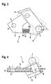
- FIG. 3 shown embodiment of a crank 1 substantially corresponds to in Fig. 2 shown and previously described embodiment.
- the spring 12 is formed as a helical compression spring, which is arranged in a region between the crank plate 2 and the pivot pin holder 8.
- the first pin 17 is a second pin 18 axially opposite, which engages from the opposite end into the spring 12 and which is integrally formed on the plate-shaped pivot pin holder 8 or fixed thereto.
- Fig. 3 is the pivot pin 7 in its unloading position, in which it against the spring force of the spring 12 due to the rod force F was adjusted. Strichliert the operating position is shown, in which a integrally formed on the plate-shaped hinge pin holder 8 stop rests laterally on the crank plate 2.
- FIG. 4 shown embodiment of a crank 1 substantially corresponds to that in the Fig. 1a and 1b shown embodiment, with the difference that the spring formed there as a bow spring 12 has been replaced by a leaf spring spring 12, wherein the leaf spring formed as spring 12 on the one hand on a crank plate top and on the other at a transition region between the pivot pin 7 and the hinge pin holder 8 is set.
- the pivot pin holder 8 in the embodiment according to Fig. 4 different from the pivot pin holder 8 according to the embodiment according to the Fig. 1a and 1b educated.
- the pivot pin holder 8 passes through the through hole 5 and has on the underside of the crank plate 2 on a stop 13, which abuts in the operating position (shown in phantom) of the pivot pin 7 on the underside of the crank plate 2.
- the unloading position is defined by a stopper 14 cooperating with a lower peripheral edge of the through-hole 5 and formed on the pivot pin holder 8.
Landscapes
- Engineering & Computer Science (AREA)
- Mechanical Engineering (AREA)
- Transmission Devices (AREA)
Priority Applications (1)
| Application Number | Priority Date | Filing Date | Title |
|---|---|---|---|
| PL09159619T PL2127968T3 (pl) | 2008-05-21 | 2009-05-07 | Korba dla napędu wycieraczki oraz napęd wycieraczki |
Applications Claiming Priority (1)
| Application Number | Priority Date | Filing Date | Title |
|---|---|---|---|
| DE102008001931A DE102008001931A1 (de) | 2008-05-21 | 2008-05-21 | Kurbel für einen Wischerantrieb sowie Wischerantrieb |
Publications (3)
| Publication Number | Publication Date |
|---|---|
| EP2127968A2 true EP2127968A2 (fr) | 2009-12-02 |
| EP2127968A3 EP2127968A3 (fr) | 2013-08-28 |
| EP2127968B1 EP2127968B1 (fr) | 2014-08-20 |
Family
ID=40933743
Family Applications (1)
| Application Number | Title | Priority Date | Filing Date |
|---|---|---|---|
| EP09159619.7A Not-in-force EP2127968B1 (fr) | 2008-05-21 | 2009-05-07 | Manivelle pour un entraînement d'essuie-glace et entraînement d'essuie-glace |
Country Status (4)
| Country | Link |
|---|---|
| EP (1) | EP2127968B1 (fr) |
| DE (1) | DE102008001931A1 (fr) |
| ES (1) | ES2500240T3 (fr) |
| PL (1) | PL2127968T3 (fr) |
Cited By (3)
| Publication number | Priority date | Publication date | Assignee | Title |
|---|---|---|---|---|
| WO2011101061A1 (fr) * | 2010-02-16 | 2011-08-25 | Robert Bosch Gmbh | Tringlerie d'essuie-glace |
| EP2738054A3 (fr) * | 2012-12-03 | 2018-04-18 | Bosch Automotive Products (Changsha) Co., Ltd | Système d'essuie-glace de véhicule, manivelle et son mécanisme de tige de liaison |
| WO2022267484A1 (fr) * | 2021-06-24 | 2022-12-29 | 华为技术有限公司 | Appareil à arbre rotatif et dispositif électronique |
Families Citing this family (1)
| Publication number | Priority date | Publication date | Assignee | Title |
|---|---|---|---|---|
| DE102016100263A1 (de) * | 2016-01-08 | 2017-07-13 | Valeo Wischersysteme Gmbh | Kurbel für einen Wischerantrieb und Wischerantrieb |
Citations (1)
| Publication number | Priority date | Publication date | Assignee | Title |
|---|---|---|---|---|
| DE10013201A1 (de) | 2000-03-17 | 2001-09-27 | Bosch Gmbh Robert | Scheibenwischerantrieb |
Family Cites Families (4)
| Publication number | Priority date | Publication date | Assignee | Title |
|---|---|---|---|---|
| DE2820104A1 (de) * | 1978-05-09 | 1979-11-15 | Bosch Gmbh Robert | Wischvorrichtung fuer scheiben von kraftfahrzeugen |
| DE4323551C2 (de) * | 1992-07-14 | 2002-12-19 | Mitsuba Corp | Scheibenwischervorrichtung für Fahrzeuge |
| JPH08128438A (ja) * | 1994-10-31 | 1996-05-21 | Musashi Seimitsu Ind Co Ltd | ボールジョイント |
| DE102006004110A1 (de) * | 2006-01-28 | 2007-08-16 | Valeo Systèmes d`Essuyage | Wischarm |
-
2008
- 2008-05-21 DE DE102008001931A patent/DE102008001931A1/de not_active Withdrawn
-
2009
- 2009-05-07 EP EP09159619.7A patent/EP2127968B1/fr not_active Not-in-force
- 2009-05-07 ES ES09159619.7T patent/ES2500240T3/es active Active
- 2009-05-07 PL PL09159619T patent/PL2127968T3/pl unknown
Patent Citations (1)
| Publication number | Priority date | Publication date | Assignee | Title |
|---|---|---|---|---|
| DE10013201A1 (de) | 2000-03-17 | 2001-09-27 | Bosch Gmbh Robert | Scheibenwischerantrieb |
Cited By (3)
| Publication number | Priority date | Publication date | Assignee | Title |
|---|---|---|---|---|
| WO2011101061A1 (fr) * | 2010-02-16 | 2011-08-25 | Robert Bosch Gmbh | Tringlerie d'essuie-glace |
| EP2738054A3 (fr) * | 2012-12-03 | 2018-04-18 | Bosch Automotive Products (Changsha) Co., Ltd | Système d'essuie-glace de véhicule, manivelle et son mécanisme de tige de liaison |
| WO2022267484A1 (fr) * | 2021-06-24 | 2022-12-29 | 华为技术有限公司 | Appareil à arbre rotatif et dispositif électronique |
Also Published As
| Publication number | Publication date |
|---|---|
| EP2127968B1 (fr) | 2014-08-20 |
| PL2127968T3 (pl) | 2015-03-31 |
| DE102008001931A1 (de) | 2009-11-26 |
| ES2500240T3 (es) | 2014-09-30 |
| EP2127968A3 (fr) | 2013-08-28 |
Similar Documents
| Publication | Publication Date | Title |
|---|---|---|
| EP3071437B1 (fr) | Ensemble calandre de radiateur pour un véhicule | |
| EP1732792B1 (fr) | Raclette d'essuie-glace | |
| EP1375273B1 (fr) | Dispositif d'essuie-glace | |
| EP2127968B1 (fr) | Manivelle pour un entraînement d'essuie-glace et entraînement d'essuie-glace | |
| EP3127800A1 (fr) | Dispositif a derailleur avant pour un derailleur de velo | |
| DE2820104A1 (de) | Wischvorrichtung fuer scheiben von kraftfahrzeugen | |
| DE202020005644U1 (de) | Mähmesservorrichtung | |
| EP1720749B1 (fr) | Bras de dispositif d'essuie-glace | |
| DE102004049552B4 (de) | Scharnier für eine Fahrzeugtür | |
| EP2123523B1 (fr) | Manivelle pour un entraînement d'essuie-glace et entraînement d'essuie-glace | |
| DE102020121746B4 (de) | Antriebseinrichtung und Luftleitvorrichtung mit einer Antriebseinrichtung | |
| WO1989000936A1 (fr) | Bras de monture d'essuie-glaces pour installations d'essuie-glaces de vehicules a moteur | |
| EP2466117B1 (fr) | Dispositif de démarrage pour un moteur à combustion interne | |
| EP3882688B1 (fr) | Charnière à ressort pour lunettes | |
| DE102006037527A1 (de) | Verbindung eines Hubarms an einer Hubwelle eines Dreipunkt-Geräteanbaus | |
| DE10360831A1 (de) | Scheibenwischvorrichtung, insbesondere für ein Kraftfahrzeug | |
| WO1999003713A1 (fr) | Element de fixation et son procede de production | |
| DE102009003189B4 (de) | Scheibenwischervorrichtung | |
| EP1936083B1 (fr) | Dispositif de support pour une charnière d'une unité de fermeture | |
| EP3044051A1 (fr) | Charnière pelliculaire pour un dispositif d'essuie-glace | |
| EP0835792B1 (fr) | Bras d'essuie-glace d'un système d'essuyage de pare-brise de véhicule | |
| WO2017178358A1 (fr) | Dispositif de bras d'essuie-glace | |
| DE202007005038U1 (de) | Klemmbefestigungsvorrichtung für eine Führungsprofilschiene eines Torantriebes sowie damit versehene Torantriebsvorrichtung | |
| DE102007061377A1 (de) | Scheibenwischerarm | |
| WO2019243175A1 (fr) | Module d'un siège de véhicule et procédé de montage d'un module |
Legal Events
| Date | Code | Title | Description |
|---|---|---|---|
| PUAI | Public reference made under article 153(3) epc to a published international application that has entered the european phase |
Free format text: ORIGINAL CODE: 0009012 |
|
| AK | Designated contracting states |
Kind code of ref document: A2 Designated state(s): AT BE BG CH CY CZ DE DK EE ES FI FR GB GR HR HU IE IS IT LI LT LU LV MC MK MT NL NO PL PT RO SE SI SK TR |
|
| PUAL | Search report despatched |
Free format text: ORIGINAL CODE: 0009013 |
|
| AK | Designated contracting states |
Kind code of ref document: A3 Designated state(s): AT BE BG CH CY CZ DE DK EE ES FI FR GB GR HR HU IE IS IT LI LT LU LV MC MK MT NL NO PL PT RO SE SI SK TR |
|
| AX | Request for extension of the european patent |
Extension state: AL BA RS |
|
| RIC1 | Information provided on ipc code assigned before grant |
Ipc: F16C 11/06 20060101ALI20130722BHEP Ipc: B60S 1/24 20060101AFI20130722BHEP |
|
| 17P | Request for examination filed |
Effective date: 20140228 |
|
| RBV | Designated contracting states (corrected) |
Designated state(s): AT BE BG CH CY CZ DE DK EE ES FI FR GB GR HR HU IE IS IT LI LT LU LV MC MK MT NL NO PL PT RO SE SI SK TR |
|
| GRAP | Despatch of communication of intention to grant a patent |
Free format text: ORIGINAL CODE: EPIDOSNIGR1 |
|
| INTG | Intention to grant announced |
Effective date: 20140523 |
|
| GRAS | Grant fee paid |
Free format text: ORIGINAL CODE: EPIDOSNIGR3 |
|
| GRAA | (expected) grant |
Free format text: ORIGINAL CODE: 0009210 |
|
| AK | Designated contracting states |
Kind code of ref document: B1 Designated state(s): AT BE BG CH CY CZ DE DK EE ES FI FR GB GR HR HU IE IS IT LI LT LU LV MC MK MT NL NO PL PT RO SE SI SK TR |
|
| REG | Reference to a national code |
Ref country code: GB Ref legal event code: FG4D Free format text: NOT ENGLISH |
|
| REG | Reference to a national code |
Ref country code: CH Ref legal event code: EP |
|
| REG | Reference to a national code |
Ref country code: AT Ref legal event code: REF Ref document number: 683265 Country of ref document: AT Kind code of ref document: T Effective date: 20140915 |
|
| REG | Reference to a national code |
Ref country code: IE Ref legal event code: FG4D Free format text: LANGUAGE OF EP DOCUMENT: GERMAN |
|
| REG | Reference to a national code |
Ref country code: ES Ref legal event code: FG2A Ref document number: 2500240 Country of ref document: ES Kind code of ref document: T3 Effective date: 20140930 |
|
| REG | Reference to a national code |
Ref country code: DE Ref legal event code: R096 Ref document number: 502009009817 Country of ref document: DE Effective date: 20141002 |
|
| REG | Reference to a national code |
Ref country code: NL Ref legal event code: VDEP Effective date: 20140820 |
|
| REG | Reference to a national code |
Ref country code: LT Ref legal event code: MG4D |
|
| PG25 | Lapsed in a contracting state [announced via postgrant information from national office to epo] |
Ref country code: FI Free format text: LAPSE BECAUSE OF FAILURE TO SUBMIT A TRANSLATION OF THE DESCRIPTION OR TO PAY THE FEE WITHIN THE PRESCRIBED TIME-LIMIT Effective date: 20140820 Ref country code: BG Free format text: LAPSE BECAUSE OF FAILURE TO SUBMIT A TRANSLATION OF THE DESCRIPTION OR TO PAY THE FEE WITHIN THE PRESCRIBED TIME-LIMIT Effective date: 20141120 Ref country code: NO Free format text: LAPSE BECAUSE OF FAILURE TO SUBMIT A TRANSLATION OF THE DESCRIPTION OR TO PAY THE FEE WITHIN THE PRESCRIBED TIME-LIMIT Effective date: 20141120 Ref country code: LT Free format text: LAPSE BECAUSE OF FAILURE TO SUBMIT A TRANSLATION OF THE DESCRIPTION OR TO PAY THE FEE WITHIN THE PRESCRIBED TIME-LIMIT Effective date: 20140820 Ref country code: PT Free format text: LAPSE BECAUSE OF FAILURE TO SUBMIT A TRANSLATION OF THE DESCRIPTION OR TO PAY THE FEE WITHIN THE PRESCRIBED TIME-LIMIT Effective date: 20141222 Ref country code: SE Free format text: LAPSE BECAUSE OF FAILURE TO SUBMIT A TRANSLATION OF THE DESCRIPTION OR TO PAY THE FEE WITHIN THE PRESCRIBED TIME-LIMIT Effective date: 20140820 Ref country code: GR Free format text: LAPSE BECAUSE OF FAILURE TO SUBMIT A TRANSLATION OF THE DESCRIPTION OR TO PAY THE FEE WITHIN THE PRESCRIBED TIME-LIMIT Effective date: 20141121 |
|
| PG25 | Lapsed in a contracting state [announced via postgrant information from national office to epo] |
Ref country code: IS Free format text: LAPSE BECAUSE OF FAILURE TO SUBMIT A TRANSLATION OF THE DESCRIPTION OR TO PAY THE FEE WITHIN THE PRESCRIBED TIME-LIMIT Effective date: 20141220 Ref country code: HR Free format text: LAPSE BECAUSE OF FAILURE TO SUBMIT A TRANSLATION OF THE DESCRIPTION OR TO PAY THE FEE WITHIN THE PRESCRIBED TIME-LIMIT Effective date: 20140820 Ref country code: LV Free format text: LAPSE BECAUSE OF FAILURE TO SUBMIT A TRANSLATION OF THE DESCRIPTION OR TO PAY THE FEE WITHIN THE PRESCRIBED TIME-LIMIT Effective date: 20140820 |
|
| PG25 | Lapsed in a contracting state [announced via postgrant information from national office to epo] |
Ref country code: NL Free format text: LAPSE BECAUSE OF FAILURE TO SUBMIT A TRANSLATION OF THE DESCRIPTION OR TO PAY THE FEE WITHIN THE PRESCRIBED TIME-LIMIT Effective date: 20140820 |
|
| REG | Reference to a national code |
Ref country code: PL Ref legal event code: T3 |
|
| PG25 | Lapsed in a contracting state [announced via postgrant information from national office to epo] |
Ref country code: DK Free format text: LAPSE BECAUSE OF FAILURE TO SUBMIT A TRANSLATION OF THE DESCRIPTION OR TO PAY THE FEE WITHIN THE PRESCRIBED TIME-LIMIT Effective date: 20140820 Ref country code: IT Free format text: LAPSE BECAUSE OF FAILURE TO SUBMIT A TRANSLATION OF THE DESCRIPTION OR TO PAY THE FEE WITHIN THE PRESCRIBED TIME-LIMIT Effective date: 20140820 Ref country code: RO Free format text: LAPSE BECAUSE OF FAILURE TO SUBMIT A TRANSLATION OF THE DESCRIPTION OR TO PAY THE FEE WITHIN THE PRESCRIBED TIME-LIMIT Effective date: 20140820 Ref country code: SK Free format text: LAPSE BECAUSE OF FAILURE TO SUBMIT A TRANSLATION OF THE DESCRIPTION OR TO PAY THE FEE WITHIN THE PRESCRIBED TIME-LIMIT Effective date: 20140820 Ref country code: EE Free format text: LAPSE BECAUSE OF FAILURE TO SUBMIT A TRANSLATION OF THE DESCRIPTION OR TO PAY THE FEE WITHIN THE PRESCRIBED TIME-LIMIT Effective date: 20140820 |
|
| REG | Reference to a national code |
Ref country code: FR Ref legal event code: PLFP Year of fee payment: 7 |
|
| REG | Reference to a national code |
Ref country code: DE Ref legal event code: R097 Ref document number: 502009009817 Country of ref document: DE |
|
| PLBE | No opposition filed within time limit |
Free format text: ORIGINAL CODE: 0009261 |
|
| STAA | Information on the status of an ep patent application or granted ep patent |
Free format text: STATUS: NO OPPOSITION FILED WITHIN TIME LIMIT |
|
| 26N | No opposition filed |
Effective date: 20150521 |
|
| PGFP | Annual fee paid to national office [announced via postgrant information from national office to epo] |
Ref country code: ES Payment date: 20150520 Year of fee payment: 7 Ref country code: CZ Payment date: 20150427 Year of fee payment: 7 |
|
| PGFP | Annual fee paid to national office [announced via postgrant information from national office to epo] |
Ref country code: PL Payment date: 20150427 Year of fee payment: 7 Ref country code: FR Payment date: 20150519 Year of fee payment: 7 |
|
| PG25 | Lapsed in a contracting state [announced via postgrant information from national office to epo] |
Ref country code: SI Free format text: LAPSE BECAUSE OF FAILURE TO SUBMIT A TRANSLATION OF THE DESCRIPTION OR TO PAY THE FEE WITHIN THE PRESCRIBED TIME-LIMIT Effective date: 20140820 |
|
| REG | Reference to a national code |
Ref country code: CH Ref legal event code: PL |
|
| GBPC | Gb: european patent ceased through non-payment of renewal fee |
Effective date: 20150507 |
|
| PG25 | Lapsed in a contracting state [announced via postgrant information from national office to epo] |
Ref country code: MC Free format text: LAPSE BECAUSE OF FAILURE TO SUBMIT A TRANSLATION OF THE DESCRIPTION OR TO PAY THE FEE WITHIN THE PRESCRIBED TIME-LIMIT Effective date: 20140820 Ref country code: LU Free format text: LAPSE BECAUSE OF FAILURE TO SUBMIT A TRANSLATION OF THE DESCRIPTION OR TO PAY THE FEE WITHIN THE PRESCRIBED TIME-LIMIT Effective date: 20150507 Ref country code: LI Free format text: LAPSE BECAUSE OF NON-PAYMENT OF DUE FEES Effective date: 20150531 Ref country code: CH Free format text: LAPSE BECAUSE OF NON-PAYMENT OF DUE FEES Effective date: 20150531 |
|
| REG | Reference to a national code |
Ref country code: IE Ref legal event code: MM4A |
|
| PG25 | Lapsed in a contracting state [announced via postgrant information from national office to epo] |
Ref country code: IE Free format text: LAPSE BECAUSE OF NON-PAYMENT OF DUE FEES Effective date: 20150507 Ref country code: GB Free format text: LAPSE BECAUSE OF NON-PAYMENT OF DUE FEES Effective date: 20150507 |
|
| REG | Reference to a national code |
Ref country code: AT Ref legal event code: MM01 Ref document number: 683265 Country of ref document: AT Kind code of ref document: T Effective date: 20150507 |
|
| PG25 | Lapsed in a contracting state [announced via postgrant information from national office to epo] |
Ref country code: AT Free format text: LAPSE BECAUSE OF NON-PAYMENT OF DUE FEES Effective date: 20150507 |
|
| PG25 | Lapsed in a contracting state [announced via postgrant information from national office to epo] |
Ref country code: MT Free format text: LAPSE BECAUSE OF FAILURE TO SUBMIT A TRANSLATION OF THE DESCRIPTION OR TO PAY THE FEE WITHIN THE PRESCRIBED TIME-LIMIT Effective date: 20140820 |
|
| PG25 | Lapsed in a contracting state [announced via postgrant information from national office to epo] |
Ref country code: CZ Free format text: LAPSE BECAUSE OF NON-PAYMENT OF DUE FEES Effective date: 20160507 |
|
| REG | Reference to a national code |
Ref country code: FR Ref legal event code: ST Effective date: 20170131 |
|
| PG25 | Lapsed in a contracting state [announced via postgrant information from national office to epo] |
Ref country code: FR Free format text: LAPSE BECAUSE OF NON-PAYMENT OF DUE FEES Effective date: 20160531 |
|
| PG25 | Lapsed in a contracting state [announced via postgrant information from national office to epo] |
Ref country code: HU Free format text: LAPSE BECAUSE OF FAILURE TO SUBMIT A TRANSLATION OF THE DESCRIPTION OR TO PAY THE FEE WITHIN THE PRESCRIBED TIME-LIMIT; INVALID AB INITIO Effective date: 20090507 |
|
| PG25 | Lapsed in a contracting state [announced via postgrant information from national office to epo] |
Ref country code: CY Free format text: LAPSE BECAUSE OF FAILURE TO SUBMIT A TRANSLATION OF THE DESCRIPTION OR TO PAY THE FEE WITHIN THE PRESCRIBED TIME-LIMIT Effective date: 20140820 |
|
| PG25 | Lapsed in a contracting state [announced via postgrant information from national office to epo] |
Ref country code: BE Free format text: LAPSE BECAUSE OF NON-PAYMENT OF DUE FEES Effective date: 20150531 |
|
| PG25 | Lapsed in a contracting state [announced via postgrant information from national office to epo] |
Ref country code: TR Free format text: LAPSE BECAUSE OF FAILURE TO SUBMIT A TRANSLATION OF THE DESCRIPTION OR TO PAY THE FEE WITHIN THE PRESCRIBED TIME-LIMIT Effective date: 20140820 |
|
| PG25 | Lapsed in a contracting state [announced via postgrant information from national office to epo] |
Ref country code: PL Free format text: LAPSE BECAUSE OF NON-PAYMENT OF DUE FEES Effective date: 20160507 |
|
| PG25 | Lapsed in a contracting state [announced via postgrant information from national office to epo] |
Ref country code: ES Free format text: LAPSE BECAUSE OF NON-PAYMENT OF DUE FEES Effective date: 20160508 |
|
| PG25 | Lapsed in a contracting state [announced via postgrant information from national office to epo] |
Ref country code: MK Free format text: LAPSE BECAUSE OF FAILURE TO SUBMIT A TRANSLATION OF THE DESCRIPTION OR TO PAY THE FEE WITHIN THE PRESCRIBED TIME-LIMIT Effective date: 20140820 |
|
| PGFP | Annual fee paid to national office [announced via postgrant information from national office to epo] |
Ref country code: DE Payment date: 20180725 Year of fee payment: 10 |
|
| REG | Reference to a national code |
Ref country code: ES Ref legal event code: FD2A Effective date: 20181128 |
|
| REG | Reference to a national code |
Ref country code: DE Ref legal event code: R119 Ref document number: 502009009817 Country of ref document: DE |
|
| PG25 | Lapsed in a contracting state [announced via postgrant information from national office to epo] |
Ref country code: DE Free format text: LAPSE BECAUSE OF NON-PAYMENT OF DUE FEES Effective date: 20191203 |