EP1375273B1 - Dispositif d'essuie-glace - Google Patents
Dispositif d'essuie-glace Download PDFInfo
- Publication number
- EP1375273B1 EP1375273B1 EP03002359A EP03002359A EP1375273B1 EP 1375273 B1 EP1375273 B1 EP 1375273B1 EP 03002359 A EP03002359 A EP 03002359A EP 03002359 A EP03002359 A EP 03002359A EP 1375273 B1 EP1375273 B1 EP 1375273B1
- Authority
- EP
- European Patent Office
- Prior art keywords
- torsion spring
- spring elements
- region
- windscreen
- elements
- Prior art date
- Legal status (The legal status is an assumption and is not a legal conclusion. Google has not performed a legal analysis and makes no representation as to the accuracy of the status listed.)
- Expired - Lifetime
Links
- 229920002430 Fibre-reinforced plastic Polymers 0.000 claims description 2
- 239000011151 fibre-reinforced plastic Substances 0.000 claims description 2
- 238000004519 manufacturing process Methods 0.000 description 7
- 238000003825 pressing Methods 0.000 description 5
- 238000005452 bending Methods 0.000 description 4
- 230000013011 mating Effects 0.000 description 2
- 238000004080 punching Methods 0.000 description 2
- 238000009434 installation Methods 0.000 description 1
- 239000004033 plastic Substances 0.000 description 1
- 229920003023 plastic Polymers 0.000 description 1
Images


Classifications
-
- B—PERFORMING OPERATIONS; TRANSPORTING
- B60—VEHICLES IN GENERAL
- B60S—SERVICING, CLEANING, REPAIRING, SUPPORTING, LIFTING, OR MANOEUVRING OF VEHICLES, NOT OTHERWISE PROVIDED FOR
- B60S1/00—Cleaning of vehicles
- B60S1/02—Cleaning windscreens, windows or optical devices
- B60S1/04—Wipers or the like, e.g. scrapers
- B60S1/32—Wipers or the like, e.g. scrapers characterised by constructional features of wiper blade arms or blades
- B60S1/34—Wiper arms; Mountings therefor
- B60S1/3425—Constructional aspects of the arm
- B60S1/3436—Mounting heads
- B60S1/344—Flat-type mounting heads
Definitions
- the invention relates to a windshield wiper device, in particular for a motor vehicle, having a wiper arm drivable by a drive, which can be folded onto a disk and folded away from a disk and to which a wiper blade can be arranged, wherein the wiper arm has a region facing the drive and a wiper blade facing area.
- Previously known windscreen wiper devices have a wiper arm which can be folded away from the window by means of a joint and folded onto the window. So that the wiper arm is pressed as firmly as possible against the disc in the folded state on the disc and thus the wiper arm remains stable in the folded away position of the disc in this folded-away position, the previously known wiper arms on a tension spring.
- a disadvantage of these conventional wiper arms is that they require a certain installation effort, which thus increases the cost of the windshield wiper device.
- the wiper arms of the previously known windscreen wiper devices have a relatively large distance to the windshield in the folded-over state on the windscreen, which is why the wiper arms can be sunk invisible badly in the switched-off state of the windscreen wiper device.
- the invention has the object to improve a windshield wiper device of the type mentioned in that the number of components required for the wiper arm is reduced.
- the invention solves the problem set by a windshield wiper device of the type mentioned, according to the invention characterized in that the region facing the drive and the wiper blade facing region of the wiper arm is connected to two Torsionsfederettin, wherein the Torsionsfederetti are provided with mutually opposite Torsionswinkeln and Torsionsfederetti have a rectangular cross-section whose width is greater than its thickness, so that the torsion spring elements are curved in the longitudinal direction of the disc or curved away from the disc.
- the wiper arm thus has in the future only the area facing the drive and the area facing the wiper blade and the two torsion spring elements.
- the hitherto required hinge for folding away the wiper arm of the disc or for folding the wiper arm to the disc can thus account for the same as the previously required tension spring.
- a wear of the wiper arm by frequently over time folding back and forth of the wiper arm to the disc and away from the disc is excluded in the future, since the joint friction is eliminated.
- the assembly work of the wiper arm is thus reduced to a very few assembly steps, which can be automated very cheaply with the simplest means.
- the wiper arm of the windshield wiper device according to the invention can be designed as a relatively flat structural unit, so that it can also be concealed, for example, in the A-pillar of a vehicle, whereby the overall aesthetic impression of the vehicle is upgraded.
- the wiper blade When the two torsion spring elements are spaced from each other, the wiper blade is optimally pressed against the disc in the folded state to the disc, and in the folded state of the disc, the wiper arm is held away from the disc with a maximum holding force.
- the two torsion spring elements may be connected to each other at their end regions by a connecting element, so that the torsion spring elements and the connecting elements form a single spring element, whereby the number of required components of the wiper arm and thus the assembly steps for its production are further reduced.
- a connecting element of the single spring element may be in one piece and the other connecting element in two parts.
- the two torsion spring elements can be arranged with its one end in a V-shaped manner on the one-part connecting element and in each case a part of the two-part connecting element can be attached to the other end of one of the torsion spring elements.
- the torsion of the torsion spring elements is achieved in this structural embodiment by pressing against each other of the V-shaped apart torsion spring elements, since the width of the Torsionsfederetti is greater than the thickness thereof.
- the torsion spring elements naturally tend to bend in the direction of least resistance moment.
- the least resistance moment have the torsion spring elements over their thickness, so that when they are pressed against each other across their thickness, they bend about their thickness center line, which corresponds to a bending line in the longitudinal direction of the Torsionsfederetti.
- the two-part connecting element has fastening means, the ends of the V-shaped apart torsion spring elements can be held together without much effort after they have been pressed against each other. If a connecting element is provided with a crank in its central region, the generation of the offset makes it possible to manufacture the opposite torsion angles from a manufacturing point of view very easily.
- torsion spring elements and / or the spring element are produced as a stamped part or alternatively as a fiber-reinforced plastic part.
- the connecting elements of the spring element can be in one piece, and the spring element can be produced as a longitudinally bent component with torsion spring elements (41, 42) twisted about its longitudinal axis.
- a spring element with these features can be produced, for example, in a punch press as a stamped and bent part in one work step.
- the region facing the drive and the wiper blade facing region of the wiper arm in each case has an opening for receiving the spring element, or these areas are each provided with two openings for receiving the two Torsionsfederetti, the entire wiper arm by simply mating the spring element with the Drive facing region and the wiper blade facing area or by simply mating the Torsionsfederetti with the drive area facing and the wiper blade facing area are mounted quickly.
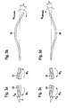
- Fig. 1 A shows a wiper arm 10 in the folded away from the disc state, the disc is not shown here in detail.
- the wiper arm 10 has a region 11, which is likewise not shown in more detail here, and a region 12 which faces a wiper blade likewise not illustrated here in detail.
- the torsion spring elements 13 have mutually opposite torsion angles, so that the torsion spring elements 13 are rotated about their longitudinal axis (see FIG Fig. 1C) , Due to the two opposite torsion angle of the torsion spring elements 13, the torsion spring elements 13 experience a bending moment in their longitudinal direction, so that the wiper arm 10, the in Fig. 1 A or in Fig.
- the Torsionsfederelement 13 has the same torsion angle when folded away from the disk on the torsion spring element 14 in the folded state to the disk and vice versa (see Fig. 3 A and 3 C ).
- the torsion spring elements 13 and 14 are inserted into the regions 11 and 12.
- the areas 11 and 12 have openings 15, 16, 17 and 18 (see Fig. 1 B and 1 C. ).
- the torsion spring elements 13 and 14 are prevented from slipping out of the areas 11 and 12.
- Fig. 2 A shows a spring element 20 with torsion spring elements 21 and 22 which are interconnected by a connecting element 23.
- Fig. 2C is the torsion spring elements 21 and 22 pressed by a force F against each other.
- Fig. 2C the torsion spring elements 21 and 22 pressed by a force F against each other.
- the torsion of the torsion spring elements 21 and 22 results from the fact that the torsion spring elements 21 and 22 have a rectangular cross section ( Fig. 3 A) whose width is greater than its thickness.
- the torsion spring elements have a smaller moment of resistance in the thickness direction than in the direction of their width, so that the force F deforms the torsion spring elements 21 and 22 from their non-twisted position, which becomes unstable upon engagement of the force F, into the twisted position. Due to the torsional deformation of the torsion spring elements 21 and 22, the torsion spring elements 21 and 22 undergo a bending in the longitudinal direction by a force component F B acting perpendicular to the torsion spring elements 21 and 22. Fig. 3 B, 3 D ). If the wiper arm folded onto the window ( Fig. 3B) folded away from the disc ( Fig.
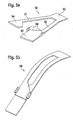
- Fig. 4 A shows a spring element 40 with two torsion spring elements 41 and 42, which are interconnected at their end regions by connecting elements 43 and 44.
- the spring element 40 can be produced very simply as a stamped and bent part. In the manufacturing process, the torsion spring elements 41 and 42 after punching out of the spring element 40 twisted about mutually opposite torsion about its longitudinal axis ( Fig. 4C) and the spring element 40 is bent along its length ( Fig. 4B) ,
- Fig. 5 A shows a spring element 50 with Torsionsfederierin 51 and 52.
- the Torsionsfederieri 51 and 52 are connected at its one end portion V-shaped by a connecting element 53 with each other.
- the torsion spring member 51 is connected at its other end to a connector member 54, and the torsion spring member 52 is connected at its other end to a connector member 55.
- the connecting element part 55 has hook elements 56, so that after pressing the torsion spring elements 51 and 52 against each other, the connecting element part 54 can be hooked into the connecting element part 55, whereby the torsion of the torsion spring elements 51 and 52 resulting from the pressing together of the torsion spring elements 51 and 52 and the resulting longitudinal bending of the spring element 50 is maintained (see Fig. 5B) ,
- Fig. 6 A shows a spring element 60 with Torsionsfederettin 61 and 62, which are connected at its one end portion V-shaped with a connecting element 63.
- the torsion spring element 61 has at its other end portion a connecting element part 64, which is provided with a hole 65.
- the torsion spring element 62 has at its other end a connecting element part 66, which is connected to a hole 67.
- a connecting means 68 for example a rivet, a screw or other fastening means known to those skilled in the art can be inserted through the overlapping holes 65 and 67.
- the torsion spring elements 61 and 62 produced by the pressing together of the torsion spring elements 61 and 62 and the thereof resulting longitudinal deflection of the spring element 60 maintained (see Fig. 6B ).
- Fig. 7 A shows a spring element 70 with two torsion spring elements 71 and 72, which are interconnected by connecting elements 73 and 74.
- the connecting element 74 is used in the production of the spring element 70 in its central region with a crank 75 ( Fig. 7B) whereby the torsion spring elements 71 and 72 arranged in a V-shaped manner on the connecting element 73 are pressed against one another such that the torsion spring elements 71 and 72 undergo torsion and the spring element 70 is bent in its longitudinal direction (FIG. Fig. 7B) , Since the spring element 70 can be produced inexpensively as a stamped part, it makes sense to also produce the crank 75 in the punching tool, whereby the production of the spring element 70 is considerably simplified.
Landscapes
- Engineering & Computer Science (AREA)
- Mechanical Engineering (AREA)
- Springs (AREA)
- Body Structure For Vehicles (AREA)
- Contacts (AREA)
Claims (8)
- Dispositif d'essuie-glace notamment pour un véhicule automobile ayant un bras d'essuie-glace (10, 30) entraîné par un moyen d'entraînement, ce bras pouvant être rabattu contre une vitre ou en être écarté par basculement, et il porte un balai d'essuie-glace,
le bras d'essuie-glace (10, 30) ayant une zone (11) tournée vers le moyen d'entraînement et une zone (12) tournée vers le balai d'essuie-glace,
la zone (11) tournée vers le moyen d'entraînement et la zone (12) du bras (10, 30) tournée vers le balai d'essuie-glace étant reliées à deux éléments de ressort de torsion (13, 14, 21, 22, 41, 42, 51, 52, 61, 62, 71, 72),
les éléments de ressort de torsion (13, 14, 21, 22, 41, 42, 51, 52, 61, 62, 71, 72) ayant des angles de torsion opposés l'un à l'autre et les éléments de ressort de torsion (13, 14, 21, 22, 41, 42, 51, 52, 61, 62, 71, 72) ont une section rectangulaire dont la largeur est supérieure à l'épaisseur pour que les éléments de ressort de torsion (13, 14, 21, 22, 41, 42, 51, 52, 61, 62, 71, 72) soient cintrés dans la direction longitudinale par rapport à la vitre ou à l'opposé de la vitre et les deux éléments de ressort de torsion (13, 14, 21, 22, 41, 42, 51, 52, 61, 62, 71, 72) étant reliés au niveau de leurs zones d'extrémités par un élément de liaison (23, 43, 44, 53, 54, 55, 63, 64, 66, 73, 74), de façon que les éléments de ressort de torsion (13, 14, 21, 22, 41, 42, 51, 52, 61, 62, 71, 72) et les éléments de liaison (23, 43, 44, 53, 54, 55, 63, 64, 66, 73, 74) constituent un unique élément de ressort (20, 40, 50, 60, 70). - Dispositif d'essuie-glace selon la revendication 1,
caractérisé en ce qu'
un élément de liaison (53, 63) est en une partie et l'autre élément de liaison est en deux parties et les deux éléments de ressort de torsion (51, 52, 61, 62) ont une de leurs extrémités, en forme de V sur l'élément de liaison (53, 63) en une seule partie et une partie (54, 55, 64, 66) respective de l'élément de liaison en deux parties est à l'autre extrémité des éléments de ressort de torsion (51, 52, 61, 62). - Dispositif d'essuie-glace selon la revendication 2,
caractérisé en ce que
l'élément de liaison en deux parties comporte des moyens de fixation (56, 68) pour maintenir réunies les extrémités des éléments de ressort de torsion (51, 52, 61, 62) qui s'écartent en forme de V après que ces éléments aient été comprimés l'un par rapport à l'autre. - Dispositif d'essuie-glace selon l'une des revendications 1 à 3,
caractérisé en ce qu'
un élément de liaison (74) comporte dans sa zone centrale une partie coudée (75). - Dispositif d'essuie-glace selon la revendication 1,
caractérisé en ce que
les éléments de liaison (43, 44) de l'élément de ressort (40) sont en une seule partie et l'élément de ressort (40) est fabriqué comme un composant courbé longitudinalement avec des éléments de ressort (41, 42) en torsion autour de leur axe longitudinal. - Dispositif d'essuie-glace selon l'une des revendications 1 à 5,
caractérisé en ce que
les éléments de ressort de torsion (13, 14) et/ou l'élément de ressort (20, 40, 50, 60, 70) sont fabriqués sous la forme de pièces embouties. - Dispositif d'essuie-glace selon l'une des revendications 1 à 5,
caractérisé en ce que
les éléments de ressort de torsion (13, 14) et/ou l'élément de ressort (20, 40, 50, 60, 70) sont fabriqués comme pièces en matière plastique renforcée par des fibres. - Dispositif d'essuie-glace selon l'une des revendications 1 à 7,
caractérisé en ce que
l'élément de ressort (20, 40, 50, 60, 70) ou les éléments de ressort de torsion (13, 14) sont enclipsés dans des ouvertures (15, 16, 17, 18) recevant l'élément de ressort (20, 40, 50, 60, 70) ou les éléments de ressort de torsion (13, 14) dans la zone (11) tournée vers le moyen d'entraînement et/ou dans la zone (12) tournée vers le balai d'essuie-glace.
Applications Claiming Priority (2)
| Application Number | Priority Date | Filing Date | Title |
|---|---|---|---|
| DE10227781 | 2002-06-21 | ||
| DE10227781A DE10227781B4 (de) | 2002-06-21 | 2002-06-21 | Scheibenwischvorrichtung |
Publications (3)
| Publication Number | Publication Date |
|---|---|
| EP1375273A2 EP1375273A2 (fr) | 2004-01-02 |
| EP1375273A3 EP1375273A3 (fr) | 2005-08-10 |
| EP1375273B1 true EP1375273B1 (fr) | 2008-04-23 |
Family
ID=29716583
Family Applications (1)
| Application Number | Title | Priority Date | Filing Date |
|---|---|---|---|
| EP03002359A Expired - Lifetime EP1375273B1 (fr) | 2002-06-21 | 2003-02-04 | Dispositif d'essuie-glace |
Country Status (4)
| Country | Link |
|---|---|
| US (1) | US6857160B2 (fr) |
| EP (1) | EP1375273B1 (fr) |
| DE (2) | DE10227781B4 (fr) |
| ES (1) | ES2301719T3 (fr) |
Families Citing this family (30)
| Publication number | Priority date | Publication date | Assignee | Title |
|---|---|---|---|---|
| US6813802B2 (en) * | 2002-06-28 | 2004-11-09 | Valeo Electrical Systems, Inc. | Prestressed wiper arm |
| DE10308786A1 (de) * | 2003-02-28 | 2004-09-09 | Robert Bosch Gmbh | Wischvorrichtung |
| DE10341457A1 (de) * | 2003-09-09 | 2005-03-31 | Robert Bosch Gmbh | Einrichtung zum Ab- und Anklappen eines Wischarms einer Scheibenwischvorrichtung an eine Kraftfahrzeugscheibe |
| DE10345803A1 (de) * | 2003-09-30 | 2005-04-14 | Robert Bosch Gmbh | Wischerarm, insbesondere für eine Scheibenwischvorrichtung eines Kraftfahrzeugs |
| DE10361746A1 (de) * | 2003-12-29 | 2005-07-28 | Robert Bosch Gmbh | Wischereinrichtung zum Wischen einer Windschutzscheibe |
| FR2875458B1 (fr) * | 2004-09-20 | 2008-02-15 | Valeo Systemes Dessuyage | Agencement pour le montage d'un bras d'essuie-glace sur une tete d'entrainement |
| US20080263805A1 (en) * | 2007-04-26 | 2008-10-30 | Gary Sebring | Camper shell windshield wiper unit |
| FR2922842B1 (fr) * | 2007-10-30 | 2009-12-18 | Valeo Systemes Dessuyage | Dispositif d'essuyage pour surface vitree de vehicule automobile |
| USD706200S1 (en) | 2010-09-22 | 2014-06-03 | Pylon Manufacturing Corporation | Windshield wiper cover |
| US9174609B2 (en) | 2011-04-21 | 2015-11-03 | Pylon Manufacturing Corp. | Wiper blade with cover |
| US9457768B2 (en) | 2011-04-21 | 2016-10-04 | Pylon Manufacturing Corp. | Vortex damping wiper blade |
| WO2013016493A1 (fr) | 2011-07-28 | 2013-01-31 | Pylon Manufacturing Corp. | Adaptateur, raccord et ensemble d'essuie-glace |
| US9381893B2 (en) | 2011-07-29 | 2016-07-05 | Pylon Manufacturing Corp. | Windshield wiper connector |
| US8806700B2 (en) | 2011-07-29 | 2014-08-19 | Pylon Manufacturing Corporation | Wiper blade connector |
| US9108595B2 (en) | 2011-07-29 | 2015-08-18 | Pylon Manufacturing Corporation | Windshield wiper connector |
| US10723322B2 (en) | 2012-02-24 | 2020-07-28 | Pylon Manufacturing Corp. | Wiper blade with cover |
| US20130219649A1 (en) | 2012-02-24 | 2013-08-29 | Pylon Manufacturing Corp. | Wiper blade |
| MX364943B (es) | 2012-02-24 | 2019-05-14 | Pylon Mfg Corp | Escobilla limpiaparabrisas. |
| US10829092B2 (en) | 2012-09-24 | 2020-11-10 | Pylon Manufacturing Corp. | Wiper blade with modular mounting base |
| US10166951B2 (en) | 2013-03-15 | 2019-01-01 | Pylon Manufacturing Corp. | Windshield wiper connector |
| US9505380B2 (en) | 2014-03-07 | 2016-11-29 | Pylon Manufacturing Corp. | Windshield wiper connector and assembly |
| USD777079S1 (en) | 2014-10-03 | 2017-01-24 | Pylon Manufacturing Corp. | Wiper blade frame |
| USD787308S1 (en) | 2014-10-03 | 2017-05-23 | Pylon Manufacturing Corp. | Wiper blade package |
| WO2017075066A1 (fr) | 2015-10-26 | 2017-05-04 | Pylon Manufacturing Corp. | Balai d'essuie-glace |
| US11040705B2 (en) | 2016-05-19 | 2021-06-22 | Pylon Manufacturing Corp. | Windshield wiper connector |
| CN109311452A (zh) | 2016-05-19 | 2019-02-05 | 电缆塔制造有限公司 | 挡风玻璃雨刮器连接器 |
| CN109715449A (zh) | 2016-05-19 | 2019-05-03 | 电缆塔制造有限公司 | 挡风玻璃雨刮器连接器 |
| WO2017201485A1 (fr) | 2016-05-19 | 2017-11-23 | Pylon Manufacturing Corp. | Connecteur d'essuie-glace |
| CN109311451B (zh) | 2016-05-19 | 2022-08-23 | 电缆塔制造有限公司 | 挡风玻璃雨刮器片 |
| FR3126376A1 (fr) * | 2021-08-31 | 2023-03-03 | Valeo Systèmes D’Essuyage | Bras monobloc de système d’essuyage comprenant plusieurs poutres longitudinales |
Family Cites Families (8)
| Publication number | Priority date | Publication date | Assignee | Title |
|---|---|---|---|---|
| DE1806719A1 (de) * | 1968-11-02 | 1970-05-21 | Daimler Benz Ag | Scheibenwischer,insbesondere fuer Kraftfahrzeuge |
| US3670356A (en) * | 1970-03-19 | 1972-06-20 | Kashira Sakamoto | Wiper arms |
| DE3142716A1 (de) * | 1981-10-28 | 1983-05-05 | Robert Bosch Gmbh, 7000 Stuttgart | Wischvorrichtung fuer scheiben von kraftfahrzeugen |
| DE3401001A1 (de) * | 1984-01-13 | 1985-07-18 | Robert Bosch Gmbh, 7000 Stuttgart | Wischvorrichtung fuer scheiben von kraftfahrzeugen |
| GB8716422D0 (en) * | 1987-07-13 | 1987-08-19 | Stevens A | Windscreen wiper arms |
| DE19651856A1 (de) * | 1996-12-13 | 1998-06-18 | Teves Gmbh Alfred | Wischarm einer Fahrzeugscheibenwischervorrichtung |
| WO2002012033A1 (fr) * | 2000-08-07 | 2002-02-14 | Valeo Auto-Electric Wischer Und Motoren Gmbh | Systeme d'essuie-glace, notamment pour automobile |
| DE10052616A1 (de) * | 2000-10-24 | 2002-05-08 | Bosch Gmbh Robert | Wischarm |
-
2002
- 2002-06-21 DE DE10227781A patent/DE10227781B4/de not_active Expired - Fee Related
-
2003
- 2003-02-04 DE DE50309667T patent/DE50309667D1/de not_active Expired - Lifetime
- 2003-02-04 EP EP03002359A patent/EP1375273B1/fr not_active Expired - Lifetime
- 2003-02-04 ES ES03002359T patent/ES2301719T3/es not_active Expired - Lifetime
- 2003-03-19 US US10/391,996 patent/US6857160B2/en not_active Expired - Fee Related
Also Published As
| Publication number | Publication date |
|---|---|
| DE10227781A1 (de) | 2004-01-08 |
| US20030233724A1 (en) | 2003-12-25 |
| US6857160B2 (en) | 2005-02-22 |
| DE10227781B4 (de) | 2013-11-28 |
| EP1375273A2 (fr) | 2004-01-02 |
| EP1375273A3 (fr) | 2005-08-10 |
| DE50309667D1 (de) | 2008-06-05 |
| ES2301719T3 (es) | 2008-07-01 |
Similar Documents
| Publication | Publication Date | Title |
|---|---|---|
| EP1375273B1 (fr) | Dispositif d'essuie-glace | |
| EP2162321B1 (fr) | Balai d'essuie-glace plat | |
| EP1732792B1 (fr) | Raclette d'essuie-glace | |
| EP1638822B1 (fr) | Systeme d'essuie-glace, destine notamment a un vehicule automobile | |
| EP1363816B1 (fr) | Bras d'essuie-glace pourvu d'une raclette reliee de maniere articulee | |
| EP1663742B1 (fr) | Dispositif destine a rabattre et a appliquer un bras de monture d'essuie-glace d'un systeme d'essuie-glace sur une vitre d'un vehicule a moteur et procede pour produire le dispositif | |
| DE102006004110A1 (de) | Wischarm | |
| EP1799518B1 (fr) | Bras d'essuie-glace et procedes de production d'un bras d'essuie-glace | |
| EP1720749B1 (fr) | Bras de dispositif d'essuie-glace | |
| EP1575813B1 (fr) | Ensemble bras d'essuie-glace comportant un bras d'essuie-glace et une raclette d'essuie-glace | |
| EP1242270B1 (fr) | Bras d'essuie-glace | |
| DE102013222996A1 (de) | Scheibenwischvorrichtung | |
| EP1670666B1 (fr) | Bras d'essuie-glace, en particulier pour dispositif essuie-glace d'un vehicule automobile | |
| WO1999042346A1 (fr) | Bras de monture d'essuie-glace a quatre points articules pour systeme d'essuie-glace | |
| EP1452413B1 (fr) | Dispositif d'essuyage | |
| EP1816043B1 (fr) | Bras d'essuie-glace, en particulier pour un véhicule automobile | |
| WO2005000647A1 (fr) | Bras d'essuie-glace | |
| EP1727716B1 (fr) | Bras essuie-glace pour un dispositif d'essuie-glace | |
| WO2015032579A1 (fr) | Charnière pelliculaire pour un dispositif d'essuie-glace | |
| EP3442838A1 (fr) | Dispositif de bras d'essuie-glace | |
| EP1436177A1 (fr) | Procede de fabrication d'un bras d'essuie-glace | |
| EP1462328B1 (fr) | Dispositif d'articulation d'un bras d'essuie-glace | |
| EP2443008B1 (fr) | Element de fixation d'un bras d'essuie glace | |
| EP2107979B1 (fr) | Bras d'essuie-glace | |
| EP1818227B1 (fr) | Bras d'essuie-glace, en particulier pour un véhicule |
Legal Events
| Date | Code | Title | Description |
|---|---|---|---|
| PUAI | Public reference made under article 153(3) epc to a published international application that has entered the european phase |
Free format text: ORIGINAL CODE: 0009012 |
|
| AK | Designated contracting states |
Kind code of ref document: A2 Designated state(s): AT BE BG CH CY CZ DE DK EE ES FI FR GB GR HU IE IT LI LU MC NL PT SE SI SK TR |
|
| AX | Request for extension of the european patent |
Extension state: AL LT LV MK RO |
|
| PUAL | Search report despatched |
Free format text: ORIGINAL CODE: 0009013 |
|
| AK | Designated contracting states |
Kind code of ref document: A3 Designated state(s): AT BE BG CH CY CZ DE DK EE ES FI FR GB GR HU IE IT LI LU MC NL PT SE SI SK TR |
|
| AX | Request for extension of the european patent |
Extension state: AL LT LV MK RO |
|
| 17P | Request for examination filed |
Effective date: 20060210 |
|
| AKX | Designation fees paid |
Designated state(s): DE ES FR GB IT |
|
| GRAP | Despatch of communication of intention to grant a patent |
Free format text: ORIGINAL CODE: EPIDOSNIGR1 |
|
| GRAS | Grant fee paid |
Free format text: ORIGINAL CODE: EPIDOSNIGR3 |
|
| GRAA | (expected) grant |
Free format text: ORIGINAL CODE: 0009210 |
|
| AK | Designated contracting states |
Kind code of ref document: B1 Designated state(s): DE ES FR GB IT |
|
| REG | Reference to a national code |
Ref country code: GB Ref legal event code: FG4D Free format text: NOT ENGLISH |
|
| REF | Corresponds to: |
Ref document number: 50309667 Country of ref document: DE Date of ref document: 20080605 Kind code of ref document: P |
|
| REG | Reference to a national code |
Ref country code: ES Ref legal event code: FG2A Ref document number: 2301719 Country of ref document: ES Kind code of ref document: T3 |
|
| ET | Fr: translation filed | ||
| PLBE | No opposition filed within time limit |
Free format text: ORIGINAL CODE: 0009261 |
|
| STAA | Information on the status of an ep patent application or granted ep patent |
Free format text: STATUS: NO OPPOSITION FILED WITHIN TIME LIMIT |
|
| 26N | No opposition filed |
Effective date: 20090126 |
|
| PGFP | Annual fee paid to national office [announced via postgrant information from national office to epo] |
Ref country code: ES Payment date: 20090225 Year of fee payment: 7 |
|
| PGFP | Annual fee paid to national office [announced via postgrant information from national office to epo] |
Ref country code: IT Payment date: 20090225 Year of fee payment: 7 |
|
| REG | Reference to a national code |
Ref country code: ES Ref legal event code: FD2A Effective date: 20110323 |
|
| PG25 | Lapsed in a contracting state [announced via postgrant information from national office to epo] |
Ref country code: IT Free format text: LAPSE BECAUSE OF NON-PAYMENT OF DUE FEES Effective date: 20100204 |
|
| PG25 | Lapsed in a contracting state [announced via postgrant information from national office to epo] |
Ref country code: ES Free format text: LAPSE BECAUSE OF NON-PAYMENT OF DUE FEES Effective date: 20110310 |
|
| PG25 | Lapsed in a contracting state [announced via postgrant information from national office to epo] |
Ref country code: ES Free format text: LAPSE BECAUSE OF NON-PAYMENT OF DUE FEES Effective date: 20100205 |
|
| PGFP | Annual fee paid to national office [announced via postgrant information from national office to epo] |
Ref country code: GB Payment date: 20130219 Year of fee payment: 11 Ref country code: FR Payment date: 20130315 Year of fee payment: 11 |
|
| GBPC | Gb: european patent ceased through non-payment of renewal fee |
Effective date: 20140204 |
|
| REG | Reference to a national code |
Ref country code: FR Ref legal event code: ST Effective date: 20141031 |
|
| PG25 | Lapsed in a contracting state [announced via postgrant information from national office to epo] |
Ref country code: GB Free format text: LAPSE BECAUSE OF NON-PAYMENT OF DUE FEES Effective date: 20140204 Ref country code: FR Free format text: LAPSE BECAUSE OF NON-PAYMENT OF DUE FEES Effective date: 20140228 |
|
| PGFP | Annual fee paid to national office [announced via postgrant information from national office to epo] |
Ref country code: DE Payment date: 20160426 Year of fee payment: 14 |
|
| REG | Reference to a national code |
Ref country code: DE Ref legal event code: R119 Ref document number: 50309667 Country of ref document: DE |
|
| PG25 | Lapsed in a contracting state [announced via postgrant information from national office to epo] |
Ref country code: DE Free format text: LAPSE BECAUSE OF NON-PAYMENT OF DUE FEES Effective date: 20170901 |