EP2127924A1 - Electrical heating device - Google Patents
Electrical heating device Download PDFInfo
- Publication number
- EP2127924A1 EP2127924A1 EP09012040A EP09012040A EP2127924A1 EP 2127924 A1 EP2127924 A1 EP 2127924A1 EP 09012040 A EP09012040 A EP 09012040A EP 09012040 A EP09012040 A EP 09012040A EP 2127924 A1 EP2127924 A1 EP 2127924A1
- Authority
- EP
- European Patent Office
- Prior art keywords
- elements
- contact
- electric heating
- circuit board
- heating device
- Prior art date
- Legal status (The legal status is an assumption and is not a legal conclusion. Google has not performed a legal analysis and makes no representation as to the accuracy of the status listed.)
- Granted
Links
Images


Classifications
-
- B—PERFORMING OPERATIONS; TRANSPORTING
- B60—VEHICLES IN GENERAL
- B60H—ARRANGEMENTS OF HEATING, COOLING, VENTILATING OR OTHER AIR-TREATING DEVICES SPECIALLY ADAPTED FOR PASSENGER OR GOODS SPACES OF VEHICLES
- B60H1/00—Heating, cooling or ventilating [HVAC] devices
- B60H1/22—Heating, cooling or ventilating [HVAC] devices the heat being derived otherwise than from the propulsion plant
- B60H1/2215—Heating, cooling or ventilating [HVAC] devices the heat being derived otherwise than from the propulsion plant the heat being derived from electric heaters
- B60H1/2221—Heating, cooling or ventilating [HVAC] devices the heat being derived otherwise than from the propulsion plant the heat being derived from electric heaters arrangements of electric heaters for heating an intermediate liquid
-
- F—MECHANICAL ENGINEERING; LIGHTING; HEATING; WEAPONS; BLASTING
- F24—HEATING; RANGES; VENTILATING
- F24H—FLUID HEATERS, e.g. WATER OR AIR HEATERS, HAVING HEAT-GENERATING MEANS, e.g. HEAT PUMPS, IN GENERAL
- F24H1/00—Water heaters, e.g. boilers, continuous-flow heaters or water-storage heaters
- F24H1/10—Continuous-flow heaters, i.e. heaters in which heat is generated only while the water is flowing, e.g. with direct contact of the water with the heating medium
-
- F—MECHANICAL ENGINEERING; LIGHTING; HEATING; WEAPONS; BLASTING
- F24—HEATING; RANGES; VENTILATING
- F24H—FLUID HEATERS, e.g. WATER OR AIR HEATERS, HAVING HEAT-GENERATING MEANS, e.g. HEAT PUMPS, IN GENERAL
- F24H1/00—Water heaters, e.g. boilers, continuous-flow heaters or water-storage heaters
- F24H1/0072—Special adaptations
- F24H1/009—Special adaptations for vehicle systems
-
- F—MECHANICAL ENGINEERING; LIGHTING; HEATING; WEAPONS; BLASTING
- F24—HEATING; RANGES; VENTILATING
- F24H—FLUID HEATERS, e.g. WATER OR AIR HEATERS, HAVING HEAT-GENERATING MEANS, e.g. HEAT PUMPS, IN GENERAL
- F24H1/00—Water heaters, e.g. boilers, continuous-flow heaters or water-storage heaters
- F24H1/10—Continuous-flow heaters, i.e. heaters in which heat is generated only while the water is flowing, e.g. with direct contact of the water with the heating medium
- F24H1/12—Continuous-flow heaters, i.e. heaters in which heat is generated only while the water is flowing, e.g. with direct contact of the water with the heating medium in which the water is kept separate from the heating medium
- F24H1/121—Continuous-flow heaters, i.e. heaters in which heat is generated only while the water is flowing, e.g. with direct contact of the water with the heating medium in which the water is kept separate from the heating medium using electric energy supply
-
- F—MECHANICAL ENGINEERING; LIGHTING; HEATING; WEAPONS; BLASTING
- F24—HEATING; RANGES; VENTILATING
- F24H—FLUID HEATERS, e.g. WATER OR AIR HEATERS, HAVING HEAT-GENERATING MEANS, e.g. HEAT PUMPS, IN GENERAL
- F24H3/00—Air heaters
- F24H3/02—Air heaters with forced circulation
- F24H3/04—Air heaters with forced circulation the air being in direct contact with the heating medium, e.g. electric heating element
- F24H3/0405—Air heaters with forced circulation the air being in direct contact with the heating medium, e.g. electric heating element using electric energy supply, e.g. the heating medium being a resistive element; Heating by direct contact, i.e. with resistive elements, electrodes and fins being bonded together without additional element in-between
- F24H3/0429—For vehicles
- F24H3/0441—Interfaces between the electrodes of a resistive heating element and the power supply means
-
- F—MECHANICAL ENGINEERING; LIGHTING; HEATING; WEAPONS; BLASTING
- F24—HEATING; RANGES; VENTILATING
- F24H—FLUID HEATERS, e.g. WATER OR AIR HEATERS, HAVING HEAT-GENERATING MEANS, e.g. HEAT PUMPS, IN GENERAL
- F24H3/00—Air heaters
- F24H3/02—Air heaters with forced circulation
- F24H3/04—Air heaters with forced circulation the air being in direct contact with the heating medium, e.g. electric heating element
- F24H3/0405—Air heaters with forced circulation the air being in direct contact with the heating medium, e.g. electric heating element using electric energy supply, e.g. the heating medium being a resistive element; Heating by direct contact, i.e. with resistive elements, electrodes and fins being bonded together without additional element in-between
- F24H3/0429—For vehicles
- F24H3/0452—Frame constructions
- F24H3/0464—Two-piece frames, e.g. two-shell frames, also including frames as a central body with two covers
-
- F—MECHANICAL ENGINEERING; LIGHTING; HEATING; WEAPONS; BLASTING
- F24—HEATING; RANGES; VENTILATING
- F24H—FLUID HEATERS, e.g. WATER OR AIR HEATERS, HAVING HEAT-GENERATING MEANS, e.g. HEAT PUMPS, IN GENERAL
- F24H3/00—Air heaters
- F24H3/02—Air heaters with forced circulation
- F24H3/04—Air heaters with forced circulation the air being in direct contact with the heating medium, e.g. electric heating element
- F24H3/0405—Air heaters with forced circulation the air being in direct contact with the heating medium, e.g. electric heating element using electric energy supply, e.g. the heating medium being a resistive element; Heating by direct contact, i.e. with resistive elements, electrodes and fins being bonded together without additional element in-between
- F24H3/0429—For vehicles
- F24H3/0452—Frame constructions
- F24H3/0476—Means for putting the electric heaters in the frame under strain, e.g. with springs
-
- F—MECHANICAL ENGINEERING; LIGHTING; HEATING; WEAPONS; BLASTING
- F24—HEATING; RANGES; VENTILATING
- F24H—FLUID HEATERS, e.g. WATER OR AIR HEATERS, HAVING HEAT-GENERATING MEANS, e.g. HEAT PUMPS, IN GENERAL
- F24H3/00—Air heaters
- F24H3/02—Air heaters with forced circulation
- F24H3/06—Air heaters with forced circulation the air being kept separate from the heating medium, e.g. using forced circulation of air over radiators
- F24H3/08—Air heaters with forced circulation the air being kept separate from the heating medium, e.g. using forced circulation of air over radiators by tubes
- F24H3/081—Air heaters with forced circulation the air being kept separate from the heating medium, e.g. using forced circulation of air over radiators by tubes using electric energy supply
- F24H3/082—The tubes being an electrical isolator containing the heater
-
- F—MECHANICAL ENGINEERING; LIGHTING; HEATING; WEAPONS; BLASTING
- F24—HEATING; RANGES; VENTILATING
- F24H—FLUID HEATERS, e.g. WATER OR AIR HEATERS, HAVING HEAT-GENERATING MEANS, e.g. HEAT PUMPS, IN GENERAL
- F24H9/00—Details
- F24H9/18—Arrangement or mounting of grates or heating means
- F24H9/1809—Arrangement or mounting of grates or heating means for water heaters
- F24H9/1818—Arrangement or mounting of electric heating means
- F24H9/1827—Positive temperature coefficient [PTC] resistor
-
- F—MECHANICAL ENGINEERING; LIGHTING; HEATING; WEAPONS; BLASTING
- F24—HEATING; RANGES; VENTILATING
- F24H—FLUID HEATERS, e.g. WATER OR AIR HEATERS, HAVING HEAT-GENERATING MEANS, e.g. HEAT PUMPS, IN GENERAL
- F24H9/00—Details
- F24H9/20—Arrangement or mounting of control or safety devices
-
- H—ELECTRICITY
- H05—ELECTRIC TECHNIQUES NOT OTHERWISE PROVIDED FOR
- H05B—ELECTRIC HEATING; ELECTRIC LIGHT SOURCES NOT OTHERWISE PROVIDED FOR; CIRCUIT ARRANGEMENTS FOR ELECTRIC LIGHT SOURCES, IN GENERAL
- H05B1/00—Details of electric heating devices
- H05B1/02—Automatic switching arrangements specially adapted to apparatus ; Control of heating devices
- H05B1/0227—Applications
- H05B1/023—Industrial applications
- H05B1/0236—Industrial applications for vehicles
-
- B—PERFORMING OPERATIONS; TRANSPORTING
- B60—VEHICLES IN GENERAL
- B60H—ARRANGEMENTS OF HEATING, COOLING, VENTILATING OR OTHER AIR-TREATING DEVICES SPECIALLY ADAPTED FOR PASSENGER OR GOODS SPACES OF VEHICLES
- B60H1/00—Heating, cooling or ventilating [HVAC] devices
- B60H1/22—Heating, cooling or ventilating [HVAC] devices the heat being derived otherwise than from the propulsion plant
- B60H2001/2268—Constructional features
- B60H2001/2278—Connectors, water supply, housing, mounting brackets
-
- H—ELECTRICITY
- H05—ELECTRIC TECHNIQUES NOT OTHERWISE PROVIDED FOR
- H05B—ELECTRIC HEATING; ELECTRIC LIGHT SOURCES NOT OTHERWISE PROVIDED FOR; CIRCUIT ARRANGEMENTS FOR ELECTRIC LIGHT SOURCES, IN GENERAL
- H05B2203/00—Aspects relating to Ohmic resistive heating covered by group H05B3/00
- H05B2203/02—Heaters using heating elements having a positive temperature coefficient
Definitions
- the present invention relates to an electric heating device for heating a flowing medium, wherein for the purposes of the present invention as a medium, in particular a liquid medium is to be understood.
- the present invention relates to an electric heating device for a motor vehicle, in particular for a motor vehicle, which is operated with a drive which gives little or no significant process heat. These include in particular hybrid drives.
- a heating device is to be specified which is particularly suitable for generating the heat required for the running processes in individual system components of a motor vehicle or at least conveying them.
- the heating device according to the invention should be particularly suitable to generate a larger amount of heat in a very short time in order to deliver it within a very short time to the corresponding equipment within the motor vehicle. Attention should be directed to the present invention to avoid overheating of the electric heater due to control errors.
- PTC heating elements in motor vehicles, which are self-regulating, since they show a higher resistance with increasing heating and thus pass a smaller amount of current.
- the PTC heating elements thus have self-regulating properties that prevent overheating of these.
- the maximum temperature that can reach a PTC resistor at a given operating voltage can be influenced by certain parameters in the production of PTC heating elements, which need not be explained here.
- PTC heating elements are therefore used regularly in radiators, which serve in particular the heating of the passenger compartment in such vehicles whose drive unit in any case leave an insufficient waste heat for air conditioning of the passenger compartment.
- the present invention is based on the problem of providing an electric heater according to the above requirements, which offers sufficient safety and avoids the above-mentioned problems.
- the present invention provides an electric heating device having the features of claim 1.
- the housing has a partition which divides the housing into a heating chamber and into a circulation chamber.
- the medium may circulate from an inlet opening into an outlet opening.
- the circulation chamber is sealed from the environment, ie only accessible via the inlet and outlet openings.
- the heating chamber On the opposite side of the circulation chamber of the circulation chamber is the heating chamber in which at least one electrical heating elements is arranged and which heats the medium flowing in the circulation chamber.
- the electric heater according to the invention has the advantage that due to the partition, the heat dissipating medium, such as water or oil, is safely separated from the electric heating element. Accordingly, any heat-dissipating medium can be used, including those media which, if appropriate, can damage the latter when directly contacting the electrical heating element and / or cause a short-circuit.
- the heat dissipating medium such as water or oil
- the housing is in consideration of a good heat conduction between the electric heating element and the circulation chamber of a good heat conducting material, preferably made of metal.
- a good heat conducting material preferably made of metal.
- metals aluminum is particularly preferred.
- the electrical heating element preferably comprises at least one PTC heating element due to the advantages already described above.
- the PTC heating element preferably rests against the dividing wall with regard to electrical insulation from the housing, with the interposition of at least one ceramic plate.
- the ceramic plate is made very thin, so that the heat conduction from the PTC heating element to the partition wall is not adversely affected substantially, but the PTC heating element is electrically isolated from the housing.
- Embodiments are also possible in which the PTC heating elements lie directly against a wall of the housing and the electrical conduction to one pole of the PTC heating elements is effected by energizing the housing, whereas another contact of the PTC heating element is electrically isolated from the housing ,
- the housing has a greater length than width and the inlet and outlet openings are recessed in the longitudinal direction at opposite ends of the housing, a sufficiently large amount of heat from the electric heating elements are transmitted to the medium can.
- the partition wall forms at least one extending in the longitudinal direction of the housing recess for receiving the at least one electric heating element in the heating chamber , which projects into the circulation chamber, is open to the heating chamber and is surrounded on both sides by the medium.
- the electrical heating element preferably has a thickness which corresponds approximately to the width of the recess.
- a plurality of recesses in the width direction of the housing are arranged in parallel one behind the other, whereby the amount transmitted by the electric heater can be increased considerably.
- the recess preferably has an approximately U-shaped cross-section, wherein the inner sides of the recess formed by the opposite legs are preferably flat.
- the U-shaped recesses are formed substantially at the same depth, ie the opposite legs of the U-shaped recess connecting webs end at the same height, so that the recesses extend equally deep into the circulation chamber , These recesses preferably terminate shortly before the bottom of the circulation chamber opposite the heating chamber.
- a plurality of electrical heating elements are added in succession in each of the recesses. The lower end of the heating elements is preferably held by engagement with the web at height.
- the electric heating element when receiving in the U-shaped recess by a likewise introduced into the recess pressure element in good contact with the opposite legs of the recess.
- the electrical heating elements as well as the opposite legs are completely flat and preferably slightly conically towards each other, wherein the pressure element should be wedge-shaped, so that the pressure element wedged the heating element in the recess and a full-surface contact between the longitudinal sides of the U- shaped recess, the heating element and the wedge ensures.
- the electric heating elements abut against at least one leg, which need not abut the electric heating element directly on the legs with respect to an electrical insulation of the housing, but are preferably electrically isolated from the housing by a thin ceramic plate.
- a thin ceramic plate With regard to improved protection against short circuit thin electrically insulating plates are arranged on both sides of the flat electrical heating elements, however, the heat transfer from the electric heating elements to the partition wall only insignificantly hinder the opposite legs of the U-shaped recess.
- the pressure element is also formed of a good heat-conducting material and is preferably the entire surface against the heating element, optionally with the interposition of the electrically insulating plate. As a result, a good heat conduction through the opposite legs of the U-shaped recess for transmission to the medium in the circulation chamber is ensured on both sides of the electric heating element.
- the pressure element is for this purpose pressed with high force in the U-shaped recess to clamp the electric heating element in the recess, by inserting the pressure element in the longitudinal direction of plate-shaped electrical heating elements.
- the later pressure surfaces of the electric heating element should be flat and smooth.
- the pressure element At high insertion forces, it is preferable to insert the pressure element against an electrically insulating plate formed by a ceramic plate whose surface opposes the insertion movement of the pressure element lower frictional resistance. Practical experiments have shown that the press-in force for introducing the pressure element to a heating element is several hundred Newtons. Not least for this reason, it is preferable to arrange a plurality of electrical heating elements in the longitudinal direction of the recess one behind the other, which are each braced by separate pressure elements in the recess.
- the pressure element preferably has a base area which corresponds to the base area of the electrical heating element, so that heat generated by the heating element can be conducted undisturbed into the legs in the transverse direction.
- electrical contact plates are preferably provided on both sides of the PTC heating element, which are electrically contacted with the PTC heating elements.
- the contact plates preferably have integrally formed thereon extension portions which project beyond the electrically insulating plates on diagonally opposite sides of the heating element.
- the size of the surface of the arranged between the insulating plates contact plates corresponds to the best possible electrical contacting of the PTC heating elements substantially facing the inside of the insulating plate outer surface of the at least one PTC heating element. Accordingly, each of the PTC heating elements lies completely on the contact plates. In contrast, the insulating plates also form a slightly protruding edge with respect to a sufficient spacing of the heating elements from the housing at the periphery of the heating elements.
- the electrical heating element may comprise one or more PTC heating elements. In particular, at a voltage above 230 V, the use of multiple PTC heating elements is preferred in order to switch these PTC heating elements as shunt resistors can.
- the resistance realized in the individual PTC heating element need not be lowered unnecessarily, which can lead to a reduced breakdown voltage.
- a single PTC heating element is realized in an electrical heating element.
- the electrical connection of the PTC heating elements takes place via the extension sections projecting over the insulating plates.
- these extension sections arranged in the recess are arranged substantially at the same height and the housing has at least one support surface for a printed circuit board in the area of the extension sections, which has contact receptacles on its underside facing the extensions, into which the Extension sections are inserted.
- the respective extension sections are contacted in a simple manner that the contact for a plurality of successively arranged in series extension sections by opposing and biased to the extension sections contact plates is formed.
- these contact plates extend substantially parallel to the extension sections and are pressed against the extension sections under prestressing when the extension sections are inserted between the contact plates. so that a good contact is guaranteed.
- the contacting can be achieved in a simple manner, that the circuit board is pushed in the longitudinal direction of the extension portions on this until the circuit board directly preferably with the interposition of electrical components or a cooling bar for these components, rest on the contact surface of the housing.
- a cover having a power and signal port and through which the heating chamber is sealed.
- This cover also has contact elements which cooperate with plug-in elements formed on the upper side of the printed circuit board.
- the contact elements are preferably in contact with each other when mounting the cover insertable and preferably extend parallel to the extension portions, so that the Aufsetziolo the cover in the longitudinal direction of the extension portions not only to a contact of the contact elements that lead to the power and signal terminal, but also a good recording of the extension sections on the opposite side of the circuit board leads.
- the electric heater according to the invention is particularly suitable as a heater for a hybrid drive of a vehicle.
- the heating device according to the invention is also suitable as a recuperator for dissipating excess energy, which is produced by generator operation of an electric motor during the regenerative braking process.
- excess electrical energy is first used to fill an electrical memory (battery) provided on the vehicle.
- electrical memory battery
- the electric heater according to the invention is suitable, by which electrical energy is converted into thermal energy, which can be released, for example, via heat exchangers to the environment or used for interior heating.
- FIG. 1 shows the embodiment of a heating device 2 with an elongate housing 4 consisting of a substantially cylindrical housing frame 4 and a screwed-on housing base 4b.
- a heating device 2 with an elongate housing 4 consisting of a substantially cylindrical housing frame 4 and a screwed-on housing base 4b.
- stubs are arranged at opposite ends of this elongate housing frame 4a, which inlet and outlet openings 6, 8 surround and which are connected via hose clamps or the like connecting leads, which lead to a substantially surrounded by the housing frame 4a circulation chamber 10 ,
- the sockets at the front ends of the housing frame 4a arranged.
- Another arrangement of the nozzles at the opposite ends of the elongate housing frame 4a is indicated by dashed lines.
- This circulation chamber 10 is separated by a partition wall 12 from an overlying heating chamber 14, in such a way that the fluid contained in the circulation chamber 10 (for example water) can not get into the heating chamber 14.
- the partition wall 12 may for example be integrally formed on the housing frame 4a.
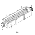
- the partition wall 12 forms a plurality of widthwise successively arranged recesses 16 which extend substantially over the entire length of the housing 4 (see. FIG. 2 ).
- the partition wall 12 accordingly has a meandering shape with deep into the circulation chamber 10 protruding recesses 16, which are completely sealed relative to the circulation chamber 10 and open to the heating chamber 14. Since these recesses 16 are preferably made of a highly conductive material, in particular metal and especially aluminum, it makes sense to produce the partition 12, for example, as a separate component and by means of forming.
- the recesses 16 have a U-shaped cross-section and extend in the longitudinal direction of the housing 4 parallel to each other.
- each of the recesses 16 are heating elements 18, which the in FIG. 4 have shown construction.
- the outside of the respective heating elements 18 is formed by ceramic plates 20.
- a plurality of PTC heating elements 22 are arranged between these ceramic plates.
- contact plates 24 made of an electrically conductive material.
- extension portions 26 Integrally formed on these contact plates 24 are extension portions 26.
- the extension portions 26 of the opposing contact plates are located on diagonally opposite sides. Accordingly, the extension portions are spaced apart from each other not only by the thickness of the PTC heating elements 22 but, moreover, are substantially separated from one another by the width of the heating elements 18.
- the extension portions 26 are doubled in thickness by once folding the material of the contact sheets 24.
- the ceramic plates 20, the PTC heating elements 22 and the contact plates 24 are preferably connected by gluing into a unit. As FIG. 4 illustrates, the ceramic plates 20 protrude beyond the PTC heating elements 22 and the contact plates 24 on all sides to form a peripheral edge.
- the introduced into the recesses 16 electrical heating elements 18 abut with one of the ceramic plates 20 on a leg 28 of the U-shaped recess 16.
- a pressure element 32 Between the opposite leg 30 and the heating element 18 is a pressure element 32, which is introduced under tension into the recess 16 and associated with a single electric heating element 18. By the respective pressure element 32, a single heating element 18 is held in the recess 16 and braced against the opposite legs 28, 30 of the recess 16.
- the heating element 18 is located with good heat conduction against the opposite legs 28, 30 at. Furthermore, the heating elements 18 are on a leg connecting the legs 28, 30 34 of the recess 16 and are accordingly set in terms of height.
- the electrical heating element 18 abuts against the lower end faces of the ceramic plates 20 on the web 34, so that the electrically conductive parts of the heating element 18 are spaced from the metallic web 34 and thus insulated.
- the depth of the recesses 16 is further selected so that the heating element 18 is at least over the height of the stacked PTC heating elements 22 flows around the medium in the circulation chamber 16, ie, the entire electric heating element 18 is received in the recess 16.
- the U-shaped recesses 16 have a slightly tapered cross-section.
- the pressure element 32 is also wedge-shaped, with a conical shape of the recess 16 corresponding slope.
- the thickness of the pressure element 32 and the electric heating element 18 substantially corresponds to the width of the respective recess 16.
- the pressure element 32 consists of a good heat-conducting material, such as aluminum and the thickness of the ceramic plates 20 is chosen so that the heat conduction from the heating elements 18 by the material of the legs 28, 30 is hardly affected. Due to the high compression of the heating elements 18 together with the pressure element 32 results in a nearly symmetrical heat dissipation on both sides of the elongated recesses 16th
- FIG. 1 protrude beyond the extension portions 34, the top of the partition wall 12 and are exposed in the heating chamber 14.
- this extension sections 26 are in FIG. 5 shown plates, namely an insulating plate 35 and a first circuit board 36 is pushed.
- the insulating plate 35 is made of an electrically insulating material and has a hole pattern corresponding to the size and location of the extension portions.
- the recessed in the insulating plate 35 openings for the extension portions 26 serve to guide the extension portions 26 and the secure insulation.
- the insulating plate 35 recesses and receptacles for from the first circuit board 36 projecting parts of the first circuit board 36.
- the first circuit board 36 has, for each recess 16, two contact receptacles 38, which are formed by bent and biased the extension portions 26 receiving extension section receptacles 40 (see, in particular FIG. 3 ).
- the contact receptacles may also be formed by two opposing contact plates, whose clear distance is selected so that the extension portions received in the contact receptacles biased against the contact plates.
- a plurality of extension sections of electrical elements arranged one behind the other are connected in series via the contact plates.
- the electrical grouping of heating elements 18 takes place by conductor tracks of the first distributor plate 36, which is accordingly also referred to as a printed circuit board.
- the first printed circuit board 36 is projected on the upper side facing away from the heating elements 18 by six tongue elements 41 and a cylindrical terminal element 42 for the positive phase, which are each arranged on the first printed circuit board 36.
- the first circuit board 36 is approximately at the level of support surfaces 43, which are provided at the front ends of the housing frame 4a.
- the first circuit board 36 has no electronic components, but only traces and the aforementioned connection elements 41, 42 and so the first circuit board 36 serves as a distribution plate only the summary of individual electric heating elements 18 into groups with a view to controlling all electrical heating elements of a group.
- the second circuit board 37 has six contact lugs 41 associated with the contact lugs 41, which are arranged on the upper side of the second circuit board 37. Furthermore, a negative connection element 45 is provided on the upper side of the second printed circuit board 37.
- the second printed circuit board 37 carries electrical switching elements, in particular semiconductor switch 46, which project beyond the second printed circuit board 37 at the end face and end with the interposition of an insulating layer 47 against the abutment surfaces 43, so that by the thus created direct contact is possible from dissipated heat generated by the semiconductor switches 46 by conduction into the housing 4 after the second circuit board 37 has been mounted at a distance from the first circuit board 36.
- the contact tongue elements 41 then engage in the corresponding plug-in contact receptacles 44.
- the positive connection element 42 extends through a recess recessed on the second printed circuit board 37 and projects beyond the second printed circuit board 37. The subsequent contacting takes place on the two connection elements 42 and 45 when a housing cover 48 is placed.
- This has a power connection 50 and a signal connection 52 on its upper side and serves to seal the heating chamber 14 from the environment.
- the embodiment shown in the drawing has 24 heating elements, each with four PTC heating elements and it has surprisingly been found that this electric heater can deliver a thermal heat output of up to 10 kW. With this power can be generated by the generator operation and not storable energy of an electric drive via the heater into thermal energy.
Abstract
Description
Die vorliegende Erfindung betrifft eine elektrische Heizvorrichtung zur Erwärmung eines strömenden Mediums, wobei im Sinne der vorliegenden Erfindung als Medium insbesondere ein flüssiges Medium zu verstehen ist. Die vorliegende Erfindung betrifft insbesondere eine elektrische Heizvorrichtung für ein Kraftfahrzeug, hier speziell für ein Kraftfahrzeug, welches mit einem Antrieb betrieben wird, der kaum oder keine erhebliche Prozesswärme abgibt. Hierzu gehören insbesondere Hybrid-Antriebe. Dementsprechend soll mit der vorliegenden Erfindung eine Heizvorrichtung angegeben werden, die sich insbesondere dazu eignet, die für die ablaufenden Prozesse in einzelnen Anlagenteile eines Kraftfahrzeuges erforderliche oder zumindest diese fördernde Wärme zu erzeugen. Die erfindungsgemäße Heizvorrichtung soll insbesondere geeignet sein, eine größere Menge von Wärme in kürzester Zeit zu erzeugen, um diese innerhalb kürzester Zeit an die entsprechenden Anlagenteile innerhalb des Kraftfahrzeuges abzugeben. Dabei soll ein Augenmerk der vorliegenden Erfindung darauf gerichtet sein, eine Überhitzung der elektrischen Heizvorrichtung aufgrund von Steuerungsfehlern zu vermeiden.The present invention relates to an electric heating device for heating a flowing medium, wherein for the purposes of the present invention as a medium, in particular a liquid medium is to be understood. In particular, the present invention relates to an electric heating device for a motor vehicle, in particular for a motor vehicle, which is operated with a drive which gives little or no significant process heat. These include in particular hybrid drives. Accordingly, with the present invention, a heating device is to be specified which is particularly suitable for generating the heat required for the running processes in individual system components of a motor vehicle or at least conveying them. The heating device according to the invention should be particularly suitable to generate a larger amount of heat in a very short time in order to deliver it within a very short time to the corresponding equipment within the motor vehicle. Attention should be directed to the present invention to avoid overheating of the electric heater due to control errors.
Es ist im Stand der Technik bekannt, so genannte Widerstandsheizelemente oder auch PTC-Heizelemente in Kraftfahrzeugen einzusetzen, die selbstregelend sind, da diese mit zunehmender Erwärmung einen höheren Widerstand zeigen und somit eine geringere Menge an Strom durchlassen. Die PTC-Heizelemente haben somit selbstregelnde Eigenschaften, die eine Überhitzung dieser verhindern. Die maximale Temperatur, die ein PTC-Widerstand bei gegebener Betriebsspannung erreichen kann, lässt sich durch bestimmte Parameter bei der Herstellung der PTC-Heizelemente beeinflussen, was hier nicht näher erläutert werden muss.It is known in the art to use so-called resistance heating elements or PTC heating elements in motor vehicles, which are self-regulating, since they show a higher resistance with increasing heating and thus pass a smaller amount of current. The PTC heating elements thus have self-regulating properties that prevent overheating of these. The maximum temperature that can reach a PTC resistor at a given operating voltage can be influenced by certain parameters in the production of PTC heating elements, which need not be explained here.
PTC-Heizelemente werden dementsprechend regelmäßig in Radiatoren eingesetzt, die insbesondere der Erwärmung des Fahrgastinnenraumes bei solchen Fahrzeugen dienen, deren Antriebseinheit jedenfalls eine unzureichende Abwärme zur Klimatisierung des Fahrgastinnenraumes abgeben.PTC heating elements are therefore used regularly in radiators, which serve in particular the heating of the passenger compartment in such vehicles whose drive unit in any case leave an insufficient waste heat for air conditioning of the passenger compartment.
Aus der
Der vorliegenden Erfindung liegt das Problem zugrunde, eine den obigen Anforderungen entsprechende elektrische Heizvorrichtung anzugeben, die eine hinreichende Sicherheit bietet und die oben genannte Probleme vermeidet.The present invention is based on the problem of providing an electric heater according to the above requirements, which offers sufficient safety and avoids the above-mentioned problems.
Zur Lösung dieses Problems wird mit der vorliegenden Erfindung eine elektrische Heizvorrichtung mit den Merkmalen von Anspruch 1 angegeben. Diese unterscheidet sich dadurch von dem Stand der Technik nach der
Die erfindungsgemäße elektrische Heizvorrichtung bietet den Vorteil, dass aufgrund der Trennwand das wärmeabführende Medium, beispielsweise Wasser oder Öl, sicher von dem elektrischen Heizelement getrennt ist. Dementsprechend kann jedes beliebige wärmeabführende Medium zum Einsatz kommen, auch solche Medien, die gegebenenfalls bei direkter Kontaktierung mit dem elektrischen Heizelement dieses beschädigen und/oder einen Kurzschluss hervorrufen können.The electric heater according to the invention has the advantage that due to the partition, the heat dissipating medium, such as water or oil, is safely separated from the electric heating element. Accordingly, any heat-dissipating medium can be used, including those media which, if appropriate, can damage the latter when directly contacting the electrical heating element and / or cause a short-circuit.
Das Gehäuse ist mit Rücksicht auf eine gute Wärmeleitung zwischen dem elektrischen Heizelement und der Zirkulationskammer aus einem gut wärmeleitenden Material, vorzugsweise aus Metall gebildet. Unter den Metallen wird insbesondere Aluminium bevorzugt.The housing is in consideration of a good heat conduction between the electric heating element and the circulation chamber of a good heat conducting material, preferably made of metal. Among the metals, aluminum is particularly preferred.
Das elektrische Heizelement umfasst aufgrund der vorstehend bereits beschriebenen Vorzüge vorzugsweise wenigstens ein PTC-Heizelement. Dabei liegt das PTC-Heizelement im Hinblick auf eine elektrische Isolierung von dem Gehäuse vorzugsweise unter Zwischenlage wenigstens einer keramischen Platte gegen die Trennwand an. Die keramische Platte ist sehr dünn ausgebildet, so dass die Wärmeleitung von dem PTC-Heizelement zu der Trennwand im wesentlichen nicht nachteilig beeinflusst wird, wohl aber das PTC-Heizelement elektrisch von dem Gehäuse isoliert ist. Es sind auch Ausführungsformen möglich, bei denen die PTC-Heizelemente unmittelbar an einer Wand des Gehäuses anliegen und die elektrische Leitung zu einem Pol der PTC-Heizelemente durch Bestromung des Gehäuses erfolgt, wohingegen ein anderer Kontakt des PTC-Heizelementes elektrisch von dem Gehäuse isoliert ist.The electrical heating element preferably comprises at least one PTC heating element due to the advantages already described above. In this case, the PTC heating element preferably rests against the dividing wall with regard to electrical insulation from the housing, with the interposition of at least one ceramic plate. The ceramic plate is made very thin, so that the heat conduction from the PTC heating element to the partition wall is not adversely affected substantially, but the PTC heating element is electrically isolated from the housing. Embodiments are also possible in which the PTC heating elements lie directly against a wall of the housing and the electrical conduction to one pole of the PTC heating elements is effected by energizing the housing, whereas another contact of the PTC heating element is electrically isolated from the housing ,
Es hat sich gezeigt, dass bei einer vorteilhaften Ausbildung, bei der das Gehäuse eine größere Länge als Breite hat und die Ein- und Auslassöffnungen in Längsrichtung an gegenüberliegenden Enden des Gehäuses ausgespart sind, eine hinreichend große Wärmemenge von den elektrischen Heizelementen an das Medium übertragen werden kann. Im Hinblick auf eine gleichmäßige und effektive Abgabe der von dem elektrischen Heizelement erzeugten Wärme an das Medium wird gemäß einer bevorzugten Weiterbildung der vorliegenden Erfindung vorgeschlagen, dass die Trennwand wenigstens eine in Längsrichtung des Gehäuses verlaufende Ausnehmung zum Aufnehmen des wenigstens einen elektrischen Heizelementes in der Heizkammer ausbildet, die in die Zirkulationskammer hineinragt, zu der Heizkammer offen ist und beidseitig von dem Medium umströmt wird. Im Hinblick auf eine gute Wärmeübertragung von dem elektrischen Heizelement an das Medium hat das elektrische Heizelement vorzugsweise eine Dicke, die in etwa der Breite der Ausnehmung entspricht. Vorzugsweise sind eine Vielzahl von Ausnehmungen in Breitenrichtung des Gehäuses parallel hintereinander angeordnet, wodurch die durch die elektrische Heizvorrichtung übertragene Menge erheblich gesteigert werden kann. Die Ausnehmung weist vorzugsweise einen in etwa U-förmigen Querschnitt auf, wobei die durch die gegenüberliegenden Schenkel gebildeten Innenseiten der Ausnehmung vorzugsweise plan sind. Im Hinblick auf die Verwendung von identischen elektrischen Heizelementen zum einfachen Aufbau einer Heizvorrichtung mit hoher Wärmeleistung sind die U-förmigen Ausnehmungen im wesentlichen mit gleicher Tiefe ausgebildet, d.h. die einander gegenüberliegenden Schenkel der U-förmigen Ausnehmung verbindenden Stege enden auf gleicher Höhe, so dass die Ausnehmungen gleich tief in die Zirkulationskammer hineinragen. Diese Ausnehmungen enden vorzugsweise kurz vor den der Heizkammer gegenüberliegenden Boden der Zirkulationskammer. Zur bestmöglichen Verwendung von Standardteilen bei der Ausbildung der elektrischen Heizelemente sind in jeder der Ausnehmungen eine Vielzahl von elektrischen Heizelementen hintereinander aufgenommen. Das untere Ende der Heizelemente wird vorzugsweise durch Anlage an dem Steg auf Höhe gehalten.It has been shown that in an advantageous embodiment, in which the housing has a greater length than width and the inlet and outlet openings are recessed in the longitudinal direction at opposite ends of the housing, a sufficiently large amount of heat from the electric heating elements are transmitted to the medium can. With regard to a uniform and effective delivery of the heat generated by the electric heating element to the medium is proposed according to a preferred embodiment of the present invention that the partition wall forms at least one extending in the longitudinal direction of the housing recess for receiving the at least one electric heating element in the heating chamber , which projects into the circulation chamber, is open to the heating chamber and is surrounded on both sides by the medium. In view of a good heat transfer from the electrical heating element to the medium, the electrical heating element preferably has a thickness which corresponds approximately to the width of the recess. Preferably, a plurality of recesses in the width direction of the housing are arranged in parallel one behind the other, whereby the amount transmitted by the electric heater can be increased considerably. The recess preferably has an approximately U-shaped cross-section, wherein the inner sides of the recess formed by the opposite legs are preferably flat. With regard to the use of identical electric heating elements for easy construction of a heater with high thermal output, the U-shaped recesses are formed substantially at the same depth, ie the opposite legs of the U-shaped recess connecting webs end at the same height, so that the recesses extend equally deep into the circulation chamber , These recesses preferably terminate shortly before the bottom of the circulation chamber opposite the heating chamber. For the best possible use of standard parts in the formation of electrical heating elements a plurality of electrical heating elements are added in succession in each of the recesses. The lower end of the heating elements is preferably held by engagement with the web at height.
Insbesondere bei der Verwendung von PTC-Heizelementen sollte im Hinblick auf die selbstregelnden Eigenschaften dieser elektrischen Heizelemente ein möglichst gleichförmiger Wärmeübergang zu beiden Seiten von flächenförmig ausgebildeten PTC-Heizelementen gewährleistet werden. Dementsprechend wird gemäß einer weiteren bevorzugten Ausgestaltung der vorliegenden Erfindung vorgeschlagen, das elektrische Heizelement bei Aufnahme in der U-förmigen Ausnehmung durch ein ebenfalls in die Ausnehmung eingebrachtes Druckelement in guter Anlage gegen die einander gegenüberliegenden Schenkel der Ausnehmung zu drücken. Vorzugsweise sind die elektrischen Heizelemente ebenso wie die einander gegenüberliegenden Schenkel vollkommen eben und verlaufen vorzugsweise leicht konisch aufeinander zu, wobei auch das Druckelement keilförmig ausgebildet sein sollte, so dass das Druckelement das Heizelement in der Ausnehmung verkeilt und eine vollflächige Anlage zwischen den Längsseiten der U-förmigen Ausnehmung, dem Heizelement und dem Keil sicherstellt. Die elektrischen Heizelemente liegen gegen zumindest einen Schenkeln an, wobei diese im Hinblick auf eine elektrische Isolierung von dem Gehäuse die elektrischen Heizelement nicht unmittelbar an den Schenkeln anliegen müssen, sondern werden vorzugsweise durch eine dünne keramische Platte elektrisch von dem Gehäuse isoliert. Mit Rücksicht auf einen verbesserten Schutz vor Kurzschluss sind an beiden Seiten der flächig ausgebildeten elektrischen Heizelemente dünne elektrisch isolierende Platten angeordnet, die jedoch die Wärmeübertragung von den elektrischen Heizelementen an die Trennwand speziell an die gegenüberliegenden Schenkel der U-förmigen Ausnehmung nur unwesentlich behindern.Especially with the use of PTC heating elements, a uniform heat transfer on both sides of flat PTC heating elements should be ensured with regard to the self-regulating properties of these electrical heating elements. Accordingly, it is proposed according to a further preferred embodiment of the present invention to press the electric heating element when receiving in the U-shaped recess by a likewise introduced into the recess pressure element in good contact with the opposite legs of the recess. Preferably, the electrical heating elements as well as the opposite legs are completely flat and preferably slightly conically towards each other, wherein the pressure element should be wedge-shaped, so that the pressure element wedged the heating element in the recess and a full-surface contact between the longitudinal sides of the U- shaped recess, the heating element and the wedge ensures. The electric heating elements abut against at least one leg, which need not abut the electric heating element directly on the legs with respect to an electrical insulation of the housing, but are preferably electrically isolated from the housing by a thin ceramic plate. With regard to improved protection against short circuit thin electrically insulating plates are arranged on both sides of the flat electrical heating elements, however, the heat transfer from the electric heating elements to the partition wall only insignificantly hinder the opposite legs of the U-shaped recess.
Das Druckelement ist ebenfalls aus einem gut wärmeleitenden Material gebildet und liegt vorzugsweise vollflächig gegen das Heizelement an, gegebenenfalls unter Zwischenlage der elektrisch isolierenden Platte. Hierdurch wird zu beiden Seiten des elektrischen Heizelementes eine gute Wärmeleitung durch die einander gegenüberliegenden Schenkel der U-förmigen Ausnehmung zur Übertragung an das Medium in der Zirkulationskammer gewährleistet. Das Druckelement wird hierzu mit hoher Kraft in die U-förmige Ausnehmung eingepresst, um das elektrische Heizelement in der Ausnehmung zu verspannen, und zwar durch Einführen des Druckelementes in Längsrichtung von plattenförmigen elektrischen Heizelementen. Die späteren Druckflächen des elektrischen Heizelementes sollten hierzu eben und glatt sein. Bei hohen Einpresskräften ist es zu bevorzugen, das Druckelement gegen eine durch eine Keramikplatte gebildete elektrisch isolierende Platte einzuschieben, deren Oberfläche der Einschiebebewegung des Druckelementes einen geringeren Reibwiderstand entgegensetzt. Praktische Versuche haben gezeigt, dass die Einpresskraft zum Einbringen des Druckelementes zu einem Heizelement mehrere hundert Newton beträgt. Nicht zuletzt aus diesem Grund ist es zu bevorzugen, mehrere elektrische Heizelemente in Längsrichtung der Ausnehmung hintereinander anzuordnen, die jeweils für sich durch separate Druckelemente in der Ausnehmung verspannt sind. Das Druckelement hat vorzugsweise eine Grundfläche, die der Grundfläche des elektrischen Heizelementes entspricht, so dass von dem Heizelement erzeugte Wärme in Querrichtung ungestört in die Schenkel geleitet werden kann.The pressure element is also formed of a good heat-conducting material and is preferably the entire surface against the heating element, optionally with the interposition of the electrically insulating plate. As a result, a good heat conduction through the opposite legs of the U-shaped recess for transmission to the medium in the circulation chamber is ensured on both sides of the electric heating element. The pressure element is for this purpose pressed with high force in the U-shaped recess to clamp the electric heating element in the recess, by inserting the pressure element in the longitudinal direction of plate-shaped electrical heating elements. The later pressure surfaces of the electric heating element should be flat and smooth. At high insertion forces, it is preferable to insert the pressure element against an electrically insulating plate formed by a ceramic plate whose surface opposes the insertion movement of the pressure element lower frictional resistance. Practical experiments have shown that the press-in force for introducing the pressure element to a heating element is several hundred Newtons. Not least for this reason, it is preferable to arrange a plurality of electrical heating elements in the longitudinal direction of the recess one behind the other, which are each braced by separate pressure elements in the recess. The pressure element preferably has a base area which corresponds to the base area of the electrical heating element, so that heat generated by the heating element can be conducted undisturbed into the legs in the transverse direction.
Zwischen den elektrisch isolierenden Platten und dem dazwischen angeordneten, wenigstens eine PTC-Heizelement sind jeweils beidseitig des PTC-Heizelementes vorzugsweise elektrische Kontaktbleche vorgesehen, welche elektrisch mit den PTC-Heizelementen kontaktiert sind. Die Kontaktbleche weisen vorzugsweise einstückig daran angeformte Verlängerungsabschnitte auf, die an diagonal gegenüberliegenden Seiten des Heizelementes die elektrisch isolierenden Platten überragen. Durch die diagonal versetzte Anordnung der Verlängerungsabschnitte wird zum einen verhindert, dass sich diese lediglich beabstandet durch die Dicke der PTC-Heizelemente einander gegenüberliegen, so dass die Gefahr einer Kurzschlussbildung weiter verringert und darüber hinaus ist der elektrische Anschluss der Verlängerungsabschnitte an eine Stromquelle, auch unter Berücksichtigung einer hinreichenden Sicherheit gegen Kurzschluss vereinfacht. Die Größe der Fläche der zwischen den isolierenden Platten angeordneten Kontaktbleche entspricht im Hinblick auf eine bestmögliche elektrische Kontaktierung der PTC-Heizelemente im wesentlichen der zu der Innenseite der isolierenden Platte zeigenden Außenfläche des wenigstens einen PTC-Heizelementes. Dementsprechend liegt jedes der PTC-Heizelemente vollflächig an den Kontaktblechen an. Demgegenüber bilden die isolierenden Platten auch im Hinblick auf eine hinreichende Beabstandung der Heizelemente von dem Gehäuse am Umfang der Heizelemente einen leicht überstehenden Rand aus. Das elektrische Heizelement kann ein oder mehrere PTC-Heizelemente aufweisen. Insbesondere bei einer Spannung über 230 V wird die Verwendung mehrerer PTC-Heizelemente bevorzugt, um diese PTC-Heizelemente als Parallelwiderstände schalten zu können. Hierdurch muss der bei dem einzelnen PTC-Heizelement realisierte Widerstand nicht unnötig abgesenkt werden, was zu einer verminderten Durchbruchspannung führen kann. Bei einer Spannung < 230 V wird vorzugsweise ein einziges PTC-Heizelement in einem elektrischen Heizelement verwirklicht.Between the electrically insulating plates and the at least one PTC heating element disposed therebetween, electrical contact plates are preferably provided on both sides of the PTC heating element, which are electrically contacted with the PTC heating elements. The contact plates preferably have integrally formed thereon extension portions which project beyond the electrically insulating plates on diagonally opposite sides of the heating element. By the diagonally offset arrangement of the extension portions is prevented on the one hand, that they are only spaced apart by the thickness of the PTC heating elements facing each other, so that the risk of shorting further reduced and beyond the electrical connection of the extension sections to a power source, also simplified taking into account a sufficient safety against short circuit. The size of the surface of the arranged between the insulating plates contact plates corresponds to the best possible electrical contacting of the PTC heating elements substantially facing the inside of the insulating plate outer surface of the at least one PTC heating element. Accordingly, each of the PTC heating elements lies completely on the contact plates. In contrast, the insulating plates also form a slightly protruding edge with respect to a sufficient spacing of the heating elements from the housing at the periphery of the heating elements. The electrical heating element may comprise one or more PTC heating elements. In particular, at a voltage above 230 V, the use of multiple PTC heating elements is preferred in order to switch these PTC heating elements as shunt resistors can. As a result, the resistance realized in the individual PTC heating element need not be lowered unnecessarily, which can lead to a reduced breakdown voltage. At a voltage <230 V, preferably a single PTC heating element is realized in an electrical heating element.
Wie bereits vorstehend erwähnt, erfolgt über die die isolierenden Platten überragenden Verlängerungsabschnitte der elektrische Anschluss der PTC-Heizelemente. Im Hinblick auf einen möglichst einfachen Anschluss der jeweiligen Verlängerungsabschnitte sind diese in der Ausnehmung angeordneten Verlängerungsabschnitte im wesentlichen höhengleich angeordnet und das Gehäuse weist im Bereich der Verlängerungsabschnitte wenigstens eine Auflagefläche für eine Leiterplatte auf, die an ihrer den Verlängerungen zugewandten Unterseite Kontaktaufnahmen aufweist, in die die Verlängerungsabschnitte einschiebbar sind. Bei einer Anordnung von mehreren Heizelementen in der Ausnehmung hintereinander, können gemäß einer bevorzugten Weiterbildung der vorliegenden Erfindung die jeweiligen Verlängerungsabschnitte auf einfache Weise dadurch kontaktiert werden, dass die Kontaktaufnahme für mehrere in Reihe hintereinander angeordnete Verlängerungsabschnitte durch einander gegenüberliegende und unter Vorspannung an den Verlängerungsabschnitten anliegende Kontaktbleche gebildet ist. Diese Kontaktbleche erstrecken sich dementsprechend im wesentlichen parallel zu den Verlängerungsabschnitten und werden bei zwischen die Kontaktbleche eingeschobenen Verlängerungsabschnitten unter Vorspannung gegen die Verlängerungsabschnitte gepresst, so dass eine gute Kontaktierung gewährleistet ist. Die Kontaktierung kann auf einfache Weise dadurch erreicht werden, dass die Leiterplatte in Längsrichtung der Verlängerungsabschnitte auf diese aufgeschoben wird, bis die Leiterplatte direkt vorzugsweise unter Zwischenlage von elektrischen Bauteilen oder einer Kühlleiste für diese Bauteile, auf der Anlagefläche des Gehäuses aufliegen.As already mentioned above, the electrical connection of the PTC heating elements takes place via the extension sections projecting over the insulating plates. With a view to the simplest possible connection of the respective extension sections, these extension sections arranged in the recess are arranged substantially at the same height and the housing has at least one support surface for a printed circuit board in the area of the extension sections, which has contact receptacles on its underside facing the extensions, into which the Extension sections are inserted. In an arrangement of a plurality of heating elements in the recess one behind the other, according to a preferred embodiment of the present invention, the respective extension sections are contacted in a simple manner that the contact for a plurality of successively arranged in series extension sections by opposing and biased to the extension sections contact plates is formed. Accordingly, these contact plates extend substantially parallel to the extension sections and are pressed against the extension sections under prestressing when the extension sections are inserted between the contact plates. so that a good contact is guaranteed. The contacting can be achieved in a simple manner, that the circuit board is pushed in the longitudinal direction of the extension portions on this until the circuit board directly preferably with the interposition of electrical components or a cooling bar for these components, rest on the contact surface of the housing.
Insbesondere beim Einsatz der Heizvorrichtung in dem Motorraum eines Kraftfahrzeuges und zur Abdichtung der Heizkammer wird gemäß einer bevorzugten Weiterbildung der vorliegenden Erfindung vorgeschlagen, eine Abdeckung vorzusehen, die einen Strom- und Signalanschluss aufweist und durch die die Heizkammer abgedichtet ist. Diese Abdeckung hat ferner Kontaktelemente, die mit an der Oberseite der Leiterplatte ausgebildeten Steckelementen zusammenwirken. Die Kontaktelemente sind vorzugsweise beim Aufsetzen der Abdeckung kontaktierend ineinander einschiebbar und erstrecken sich vorzugsweise parallel zu den Verlängerungsabschnitten, so dass die Aufsetzbewegung der Abdeckung in Längsrichtung der Verlängerungsabschnitte nicht nur zu einer Kontaktierung der Kontaktelemente, die zu dem Strom- und Signalanschluss führen, sondern auch zu einer guten Aufnahme der Verlängerungsabschnitte an der gegenüberliegenden Seite der Leiterplatte führt.In particular, when using the heater in the engine compartment of a motor vehicle and for sealing the heating chamber is proposed according to a preferred embodiment of the present invention to provide a cover having a power and signal port and through which the heating chamber is sealed. This cover also has contact elements which cooperate with plug-in elements formed on the upper side of the printed circuit board. The contact elements are preferably in contact with each other when mounting the cover insertable and preferably extend parallel to the extension portions, so that the Aufsetzbewegung the cover in the longitudinal direction of the extension portions not only to a contact of the contact elements that lead to the power and signal terminal, but also a good recording of the extension sections on the opposite side of the circuit board leads.
Die erfindungsgemäße elektrische Heizvorrichtung eignet sich insbesondere als Heizvorrichtung für einen Hybrid-Antrieb eines Fahrzeuges. Darüber hinaus eignet sich die erfindungsgemäße Heizvorrichtung auch als Rekuperator zur Ableitung überschüssiger Energie, welche durch Generatorbetrieb eines Elektromotors beim regenerativen Bremsvorgang entsteht. Eine solche überschüssige elektrische Energie wird zunächst zum Auffüllen eines an dem Fahrzeug vorgesehenen elektrischen Speichers (Batterie) genutzt. Wenn aber auch dieser Speicher vollständig geladen ist, muss elektrische Energie abgeleitet werden und hierzu eignet sich insbesondere die erfindungsgemäße elektrische Heizvorrichtung, durch die elektrische Energie in thermische Energie umgeformt wird, die beispielsweise über Wärmetauscher an die Umgebung abgegeben oder für die Innenraumheizung genutzt werden kann.The electric heater according to the invention is particularly suitable as a heater for a hybrid drive of a vehicle. In addition, the heating device according to the invention is also suitable as a recuperator for dissipating excess energy, which is produced by generator operation of an electric motor during the regenerative braking process. Such excess electrical energy is first used to fill an electrical memory (battery) provided on the vehicle. However, if this memory is also fully charged, electrical energy must be dissipated and, in particular, the electric heater according to the invention is suitable, by which electrical energy is converted into thermal energy, which can be released, for example, via heat exchangers to the environment or used for interior heating.
Die vorliegende Erfindung wird nachfolgend anhand eines Ausführungsbeispiels in Verbindung mit der Zeichnung näher erläutert. In dieser zeigen:
- Figur 1
- eine perspektivische Draufsicht auf einen Teil des Ausführungsbeispiels bei geöffneter Abdeckung;
Figur 2- eine perspektivische Draufsicht auf den unteren Teil des Gehäuses bei abgenommenem Gehäuseboden;
- Figur 3
- eine Längsschnittansicht durch das in
Figur 1 gezeigte Ausführungsbeispiel; - Figur 4
- eine perspektivische Draufsicht auf ein Ausführungsbeispiel eines elektrischen Heizelementes, welches in der Heizvorrichtung nach den
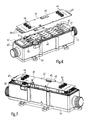
Figuren 1 bis 3 Verwendung findet; - Figur 5
- zwei auf das in
Figur 1 gezeigte Teil aufzusetzende Platten; Figur 6- das Ausführungsbeispiel nach
Figur 1 bei auf das Teil aufgesetzten Platten gemäßFigur 5 ; - Figur 7
- das Ausführungsbeispiel nach
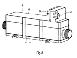
Figur 1 bei aufgesetzter zweiter Leiterplatte; und Figur 8- das in den vorherigen Figuren gezeigte Ausführungsbeispiel bei aufgesetzter Abdeckung.
- FIG. 1
- a perspective top view of a portion of the embodiment with the cover open;
- FIG. 2
- a top perspective view of the lower part of the housing with the housing bottom removed;
- FIG. 3
- a longitudinal sectional view through the in
FIG. 1 embodiment shown; - FIG. 4
- a perspective top view of an embodiment of an electric heating element, which in the heater according to the
FIGS. 1 to 3 Use finds; - FIG. 5
- two on the in
FIG. 1 shown part aufzusetzende plates; - FIG. 6
- the embodiment according to
FIG. 1 with plates placed on the part according toFIG. 5 ; - FIG. 7
- the embodiment according to
FIG. 1 with attached second circuit board; and - FIG. 8
- the embodiment shown in the previous figures with attached cover.
Die
Wie
In jeder der Ausnehmungen 16 befinden sich Heizelemente 18, welche den in
Die keramischen Platten 20, die PTC-Heizelemente 22 und die Kontaktbleche 24 sind vorzugsweise durch Kleben zu einer Einheit verbunden. Wie
Die U-förmigen Ausnehmungen 16 haben einen leicht konisch zulaufenden Querschnitt. Das Druckelement 32 ist ebenfalls keilförmig ausgebildet, und zwar mit einer den konischen Verlauf der Ausnehmung 16 entsprechenden Steigung. Die Dicke des Druckelementes 32 und des elektrischen Heizelementes 18 entspricht im wesentlichen Breite der jeweiligen Ausnehmung 16.The U-shaped recesses 16 have a slightly tapered cross-section. The
Das Druckelement 32 besteht aus einem gut wärmeleitenden Material, beispielsweise Aluminium und die Dicke der keramischen Platten 20 ist so gewählt, dass die Wärmeleitung von den Heizelementen 18 durch das Material der Schenkel 28, 30 kaum beeinträchtigt wird. Aufgrund der hohen Verpressung der Heizelemente 18 zusammen mit dem Druckelement 32 ergibt sich eine nahezu symmetrische Wärmeabfuhr zu beiden Seiten der länglichen Ausnehmungen 16.The
Wie
Die erste Leiterplatte 36 weist zu jeder Ausnehmung 16 zwei Kontaktaufnahmen 38 auf, die durch gebogene und unter Vorspannung die Verlängerungsabschnitte 26 aufnehmende Verlängerungsabschnittaufnahmen 40 gebildet sind (vgl. insbesondere
Die erste Leiterplatte 36 wird auf der den Heizelementen 18 abgewandten Oberseite durch sechs Steckzungenelemente 41 sowie ein zylindrisches Anschlusselement 42 für die Plusphase überragt, die jeweils an der ersten Leiterplatte 36 angeordnet sind. Die erste Leiterplatte 36 liegt in etwa auf Höhe von Auflageflächen 43, die an den stirnseitigen Enden des Gehäuserahmens 4a vorgesehen sind. Die erste Leiterplatte 36 weist keine elektronischen Bauteile auf, sondern lediglich Leiterbahnen und die vorerwähnten Anschlusselemente 41, 42 und so dient die erste Leiterplatte 36 als Verteilerplatte lediglich der Zusammenfassung von einzelnen elektrischen Heizelementen 18 zu Gruppen im Hinblick auf eine Steuerung sämtlicher elektrischer Heizelemente einer Gruppe.The first printed
Die zweite Leiterplatte 37 hat sechs den Kontaktzungenelementen 41 zugeordnete Steckkontaktaufnahmen 44, die an der Oberseite der zweiten Leiterplatte 37 angeordnet sind. Ferner ist auf der Oberseite der zweiten Leiterplatte 37 ein Minus-Anschlusselement 45 vorgesehen. An ihrer Unterseite trägt die zweite Leiterplatte 37 elektrische Schaltelemente, insbesondere Halbleiterschalter 46, welche die zweite Leiterplatte 37 stirnseitig bzw. endseitig überragen und unter Zwischenlage einer Isolierschicht 47 gegen die Anlageflächen 43 anliegen, so dass durch den so geschaffenen unmittelbaren Kontakt die Möglichkeit besteht, von den Halbleiterschaltern 46 erzeugte Verlustwärme durch Leitung in das Gehäuse 4 abzuleiten, nachdem die zweite Leiterplatte 37 mit Abstand zu der ersten Leiterplatte 36 montiert worden ist. Die Kontaktzungenelemente 41 greifen dann in die entsprechenden Steckkontaktaufnahmen 44 ein. Das Plus-Anschlusselement 42 durchragt eine an der zweiten Leiterplatte 37 ausgesparte Ausnehmung und überragt die zweite Leiterplatte 37. An den beiden Anschlusselementen 42 und 45 erfolgt die nachfolgende Kontaktierung beim Aufsetzen einer Gehäuseabdeckung 48. Diese weist an ihrer Oberseite einen Stromanschluss 50 und einen Signalanschluss 52 auf und dient der Abdichtung der Heizkammer 14 gegenüber der Umgebung.The
Das in der Zeichnung gezeigte Ausführungsbeispiel hat 24 Heizelemente mit jeweils vier PTC-Heizelementen und es hat sich überraschenderweise gezeigt, dass diese elektrische Heizvorrichtung eine thermische Wärmeleistung von bis über 10 kW abgeben kann. Mit dieser Leistung lässt sich die durch den Generatorbetrieb entstehende und nicht speicherbare Energie eines Elektroantriebes über die Heizvorrichtung in thermische Energie umwandeln.The embodiment shown in the drawing has 24 heating elements, each with four PTC heating elements and it has surprisingly been found that this electric heater can deliver a thermal heat output of up to 10 kW. With this power can be generated by the generator operation and not storable energy of an electric drive via the heater into thermal energy.
- 22
- Heizvorrichtungheater
- 44
- Gehäusecasing
- 4a4a
- Gehäuserahmenhousing frame
- 4b4b
- Gehäusebodencaseback
- 66
- Einlassöffnunginlet port
- 88th
- Auslassöffnungoutlet
- 1010
- Zirkulationskammercirculation chamber
- 1212
- Trennwandpartition wall
- 1414
- Heizkammerheating chamber
- 1616
- Ausnehmungrecess
- 1818
- Heizelementheating element
- 2020
- keramische Platteceramic plate
- 2222
- PTC-HeizelementPTC heating element
- 2424
- Kontaktblechcontact sheet
- 2626
- Verlängerungsabschnittextension section
- 2828
- Schenkelleg
- 3030
- Schenkelleg
- 3232
- Druckelementpressure element
- 3434
- Stegweb
- 3535
- Isolierplatteinsulation
- 3636
- erste LeiterplatteNerteilerplattefirst printed circuit board splitter plate
- 3737
- zweite Leiterplattesecond circuit board
- 3838
- Kontaktaufnahmecontact
- 4040
- VerlängerungsabschnittaufnahmeExtension section Recording
- 4141
- KontaktzungenelementeContact tongue elements
- 4242
- Plus-AnschlusselementPlus terminal
- 4343
- Anlageflächecontact surface
- 4444
- SteckkontaktaufnahmePlug contact receiving
- 4545
- Minus-AnschlusselementMinus terminal
- 4646
- HalbleiterschalterSemiconductor switches
- 4747
- Isolierschichtinsulating
- 4848
- Gehäuseabdeckunghousing cover
- 5050
- Stromanschlusspower connection
- 5252
- Signalanschlusssignal connection
Claims (13)
Priority Applications (1)
| Application Number | Priority Date | Filing Date | Title |
|---|---|---|---|
| DE502006008687T DE502006008687D1 (en) | 2006-06-28 | 2006-06-28 | Electric heater |
Applications Claiming Priority (1)
| Application Number | Priority Date | Filing Date | Title |
|---|---|---|---|
| EP06013287A EP1872986B1 (en) | 2006-06-28 | 2006-06-28 | Electrical heating device |
Related Parent Applications (2)
| Application Number | Title | Priority Date | Filing Date |
|---|---|---|---|
| EP06013287.5 Division | 2006-06-28 | ||
| EP06013287A Division EP1872986B1 (en) | 2006-06-28 | 2006-06-28 | Electrical heating device |
Publications (3)
| Publication Number | Publication Date |
|---|---|
| EP2127924A1 true EP2127924A1 (en) | 2009-12-02 |
| EP2127924A8 EP2127924A8 (en) | 2010-06-30 |
| EP2127924B1 EP2127924B1 (en) | 2011-01-05 |
Family
ID=37188680
Family Applications (2)
| Application Number | Title | Priority Date | Filing Date |
|---|---|---|---|
| EP09012040A Active EP2127924B1 (en) | 2006-06-28 | 2006-06-28 | Electrical heating device |
| EP06013287A Expired - Fee Related EP1872986B1 (en) | 2006-06-28 | 2006-06-28 | Electrical heating device |
Family Applications After (1)
| Application Number | Title | Priority Date | Filing Date |
|---|---|---|---|
| EP06013287A Expired - Fee Related EP1872986B1 (en) | 2006-06-28 | 2006-06-28 | Electrical heating device |
Country Status (7)
| Country | Link |
|---|---|
| US (1) | US8946599B2 (en) |
| EP (2) | EP2127924B1 (en) |
| JP (1) | JP4732404B2 (en) |
| KR (1) | KR100870058B1 (en) |
| CN (1) | CN100567843C (en) |
| DE (1) | DE502006008687D1 (en) |
| ES (2) | ES2354964T3 (en) |
Cited By (6)
| Publication number | Priority date | Publication date | Assignee | Title |
|---|---|---|---|---|
| EP2515388A1 (en) | 2011-04-18 | 2012-10-24 | Eberspächer catem GmbH & Co. KG | Electric heating device |
| DE102011080217A1 (en) | 2011-08-01 | 2013-02-07 | Behr Gmbh & Co. Kg | Air conditioning apparatus for conditioning air in inner space of motor car, has heating devices hydraulically separated with respect to coolant such that zones of heat exchanger are heated by heating devices in independent manner |
| CN107933246A (en) * | 2017-12-30 | 2018-04-20 | 江苏超力电器有限公司 | A kind of integral in-vehicle hot-water heating PTC calandria sink assemblies |
| DE202020000689U1 (en) | 2020-02-19 | 2020-03-16 | Eberspächer Catem Gmbh & Co. Kg | Control device and electrical heating device comprising one |
| DE102021112690A1 (en) | 2020-05-15 | 2021-11-18 | Eberspächer Catem Gmbh & Co. Kg | PTC heating device and process for their manufacture |
| DE102022109556A1 (en) | 2022-04-20 | 2023-10-26 | Eberspächer Catem Gmbh & Co. Kg | Electric heater |
Families Citing this family (146)
| Publication number | Priority date | Publication date | Assignee | Title |
|---|---|---|---|---|
| US20110062137A1 (en) * | 2007-07-18 | 2011-03-17 | Chia-Hsiung Wu | Vehicular fluid heater |
| KR100871896B1 (en) * | 2007-09-10 | 2008-12-05 | 박연홍 | Direct current type heater which have a electromagnetic waves reduce function |
| FR2925439A1 (en) * | 2008-04-14 | 2009-06-26 | Valeo Systemes Dessuyage | Liquid e.g. windscreen washer liquid, heating device for windscreen, of motor vehicle, has three resistors, where one of resistors indirectly heats liquid, and printed circuit board controlling simultaneous supply or selection of resistors |
| DE102008033142A1 (en) | 2008-07-15 | 2010-01-21 | Eichenauer Heizelemente Gmbh & Co. Kg | car heater |
| FR2938633B1 (en) * | 2008-09-05 | 2015-01-02 | Valeo Systemes Dessuyage | LIQUID HEATING DEVICE FOR MOTOR VEHICLE |
| KR20100055262A (en) * | 2008-11-17 | 2010-05-26 | 현대자동차주식회사 | High capacity ptc heater |
| EP2236330B1 (en) | 2009-03-30 | 2011-09-28 | Eberspächer catem GmbH & Co. KG | Electric heater for a motor vehicle |
| DE102009038978A1 (en) * | 2009-08-21 | 2011-03-03 | Beru Ag | Device for heating liquids |
| EP2299200B1 (en) | 2009-09-22 | 2013-02-06 | Eberspächer catem GmbH & Co. KG | Electric heating device |
| WO2011054970A2 (en) | 2009-11-09 | 2011-05-12 | Dbk David + Baader Gmbh | Electric heater |
| FR2954467B1 (en) * | 2009-12-23 | 2014-09-12 | Valeo Systemes Thermiques | ELECTRICAL HEATING DEVICE AND CORRESPONDING HEATING APPARATUS |
| JP2011152907A (en) * | 2010-01-28 | 2011-08-11 | Mitsubishi Heavy Ind Ltd | Electric heating system and vehicular air conditioner |
| DE102010021165A1 (en) * | 2010-02-19 | 2011-08-25 | Epcos Ag, 81669 | heating arrangement |
| JP5535740B2 (en) | 2010-04-14 | 2014-07-02 | 三菱重工業株式会社 | Heat medium heating device and vehicle air conditioner using the same |
| JP5535742B2 (en) * | 2010-04-19 | 2014-07-02 | 三菱重工業株式会社 | Heat medium heating device and vehicle air conditioner using the same |
| JP2012056351A (en) * | 2010-09-06 | 2012-03-22 | Mitsubishi Heavy Ind Ltd | Heat medium heating device and air conditioning apparatus for vehicle provided with same |
| EP2428746B8 (en) | 2010-09-13 | 2021-12-29 | MAHLE Behr GmbH & Co. KG | Heat exchanger |
| EP2428747B1 (en) * | 2010-09-13 | 2015-04-08 | MAHLE Behr GmbH & Co. KG | Heat exchanger |
| JP2012096779A (en) | 2010-10-07 | 2012-05-24 | Mitsubishi Heavy Ind Ltd | Heat-medium heating device and vehicle air conditioning device provided with the same |
| EP2440005B1 (en) * | 2010-10-08 | 2015-12-23 | Eberspächer catem GmbH & Co. KG | Electric heating device and method for its production |
| EP2440006B1 (en) | 2010-10-08 | 2015-02-25 | Eberspächer catem GmbH & Co. KG | Electric heating device |
| EP2440004B1 (en) | 2010-10-08 | 2015-02-25 | Eberspächer catem GmbH & Co. KG | Electric heating device |
| JP2012107804A (en) | 2010-11-17 | 2012-06-07 | Mitsubishi Heavy Ind Ltd | Laminated heat exchanger, and heat medium heating apparatus and in-vehicle air-conditioning apparatus using the laminated heat exchanger |
| JP2012131331A (en) * | 2010-12-21 | 2012-07-12 | Sanden Corp | Vehicle heating apparatus |
| DE102011003296A1 (en) | 2011-01-28 | 2012-08-02 | Behr Gmbh & Co. Kg | Heat exchanger |
| JP2012196985A (en) * | 2011-03-18 | 2012-10-18 | Mitsubishi Heavy Ind Ltd | Heater for heat medium and air conditioner for vehicle with the same |
| JP5951205B2 (en) | 2011-03-25 | 2016-07-13 | 三菱重工業株式会社 | Heat medium heating device and vehicle air conditioner equipped with the same |
| EP2626647B1 (en) * | 2011-03-30 | 2014-06-11 | Eberspächer catem GmbH & Co. KG | Method for producing a plate element comprising a circuit board |
| JP2012218557A (en) * | 2011-04-07 | 2012-11-12 | Mitsubishi Heavy Ind Ltd | Heat medium heating device, and vehicle air conditioner equipped with the same |
| US8927910B2 (en) * | 2011-04-29 | 2015-01-06 | Board Of Regents Of The Nevada System Of Higher Education, On Behalf Of The University Of Nevada, Reno | High power-density plane-surface heating element |
| FR2979693B1 (en) * | 2011-09-06 | 2013-08-23 | Valeo Systemes Thermiques | ELECTRICAL HEATING DEVICE FOR A MOTOR VEHICLE, AND HEATING AND / OR AIR CONDITIONING APPARATUS THEREFOR |
| FR2979692B1 (en) | 2011-09-06 | 2018-06-15 | Valeo Systemes Thermiques | ELECTRICAL HEATING DEVICE FOR A MOTOR VEHICLE, AND HEATING AND / OR AIR CONDITIONING APPARATUS THEREFOR |
| DE102011088773A1 (en) | 2011-12-15 | 2013-06-20 | Behr Gmbh & Co. Kg | Electrically operated heater |
| JP5979892B2 (en) | 2012-02-01 | 2016-08-31 | 三菱重工業株式会社 | Heat medium heating device and vehicle air conditioner equipped with the same |
| FR2987314B1 (en) | 2012-02-29 | 2014-03-28 | Valeo Systemes Thermiques | ELECTRIC FLUID HEATING DEVICE FOR A MOTOR VEHICLE AND HEATING AND / OR AIR CONDITIONING APPARATUS THEREFOR |
| JP2013180690A (en) * | 2012-03-02 | 2013-09-12 | Mitsubishi Heavy Ind Ltd | Heat medium heating device and vehicle air conditioner including the same |
| DE102012207301A1 (en) * | 2012-05-02 | 2013-11-07 | Webasto Ag | A heating device for a vehicle and method for cooling an electronic control device of the heating device |
| CN103423858B (en) * | 2012-05-24 | 2016-08-03 | 中国核动力研究设计院 | A kind of large power, electrically heating heat exchanger |
| CN103423871B (en) * | 2012-05-25 | 2015-08-26 | 比亚迪股份有限公司 | A kind of housing of electric heater unit, electric heater unit and electric motor car |
| DE102012104917B4 (en) | 2012-06-06 | 2023-03-23 | Eichenauer Heizelemente Gmbh & Co. Kg | Electrical heating device |
| CN103517467B (en) * | 2012-06-27 | 2016-03-09 | 比亚迪股份有限公司 | A kind of PTC electric heating element, electric heater unit and electric motor car |
| CN103542528B (en) * | 2012-07-13 | 2015-04-22 | 比亚迪股份有限公司 | Electric heating device and electric vehicle |
| CN103517469B (en) * | 2012-06-27 | 2015-03-04 | 比亚迪股份有限公司 | PTC electrical heating element, electric heater unit and electric car |
| CN103517468B (en) * | 2012-06-27 | 2015-03-04 | 比亚迪股份有限公司 | PTC electrical heating element, electric heater unit and electric car |
| WO2014000666A1 (en) * | 2012-06-27 | 2014-01-03 | Shenzhen Byd Auto R&D Company Limited | Ptc electric heating assembly, electric heating device and electric vehicle |
| CN103542525B (en) * | 2012-07-13 | 2015-11-25 | 比亚迪股份有限公司 | A kind of electric heater unit and electric motor car |
| KR101419728B1 (en) * | 2012-08-27 | 2014-07-17 | 동아하이테크 주식회사 | Heating device for coolant of vehicle |
| CN103634952B (en) * | 2012-08-28 | 2016-03-30 | 比亚迪股份有限公司 | A kind of PTC electric heating element, electric heater unit and electric motor car |
| FR2995069B1 (en) * | 2012-08-30 | 2018-12-07 | Valeo Systemes Thermiques | DEVICE FOR ELECTRICALLY HEATING FLUID FOR MOTOR VEHICLE |
| FR2994891B1 (en) * | 2012-09-06 | 2016-10-21 | Valeo Systemes Thermiques | ELECTRIC FLUID HEATING DEVICE FOR MOTOR VEHICLE, HEATING CIRCUIT, AND HEATING AND / OR AIR CONDITIONING APPARATUS THEREOF |
| EP2734007B1 (en) * | 2012-11-14 | 2016-09-21 | Betacera Inc. | Electrical heating device and equipment with pluggable heating module |
| FR3003809B1 (en) * | 2013-03-26 | 2016-12-16 | Valeo Systemes Thermiques | DEVICE FOR ELECTRICALLY HEATING FLUID FOR MOTOR VEHICLE AND HEATING CIRCUIT THEREFOR |
| BE1023731B1 (en) * | 2013-04-03 | 2017-07-03 | Volante Nino | DEVICE FOR PREHEATING A FLUID, IN PARTICULAR A COOLING FLUID OF A COMBUSTION ENGINE |
| EP2796804B1 (en) | 2013-04-26 | 2015-07-15 | Eberspächer catem GmbH & Co. KG | Sealed housing and method of forming the same |
| EP2797381B1 (en) | 2013-04-26 | 2016-03-09 | Eberspächer catem GmbH & Co. KG | Electric heating device and method for its production |
| CN103253106A (en) * | 2013-05-15 | 2013-08-21 | 江苏超力电器有限公司 | Water heater of new energy automobile |
| JP2014225348A (en) * | 2013-05-15 | 2014-12-04 | 三菱重工オートモーティブサーマルシステムズ株式会社 | Heat medium heating device, method of manufacturing the same, and vehicular air conditioner |
| DE102013105270A1 (en) * | 2013-05-23 | 2014-11-27 | Borgwarner Beru Systems Gmbh | Heater |
| CN103278036B (en) * | 2013-06-14 | 2015-08-05 | 东风汽车公司 | A kind of heater ensureing surperficial laminating rate |
| NO336209B1 (en) * | 2013-11-15 | 2015-06-15 | Defa As | Contact Heats |
| EP2884197B1 (en) | 2013-12-13 | 2017-02-08 | Eberspächer catem GmbH & Co. KG | Electric heating device and method for its production |
| EP2884198B1 (en) | 2013-12-13 | 2016-11-23 | Eberspächer catem GmbH & Co. KG | Electric heating device |
| EP2884817B1 (en) | 2013-12-13 | 2017-08-30 | Eberspächer catem GmbH & Co. KG | Electric heating device and method for its production |
| EP2884199B1 (en) | 2013-12-13 | 2016-11-23 | Eberspächer catem GmbH & Co. KG | Electric heating device |
| DE202014006425U1 (en) | 2014-01-24 | 2014-08-22 | Eberspächer Catem Gmbh & Co. Kg | Water heater and heating system for an electrically operated vehicle with a water heater |
| NO337089B1 (en) * | 2014-03-13 | 2016-01-18 | Defa As | Fluid heating device |
| EP2933577B1 (en) | 2014-04-14 | 2017-12-06 | Mahle Behr France Rouffach S.A.S | Electric heating device |
| DE202014003827U1 (en) * | 2014-05-08 | 2015-08-12 | I.G. Bauerhin Gmbh | Heating device with a temperature detection associated therewith for heating surfaces in the interior of a vehicle |
| FR3023118B1 (en) * | 2014-06-25 | 2019-07-05 | Psa Automobiles Sa. | DEVICE FOR HEATING A LIQUID FOR A MOTOR VEHICLE AND ASSEMBLY COMPRISING SUCH A DEVICE. |
| CN105530716B (en) * | 2014-12-18 | 2016-11-23 | 比亚迪股份有限公司 | Calandria assembly and the automobile with it |
| KR101684260B1 (en) | 2015-03-02 | 2016-12-12 | 우리산업 주식회사 | Heating apparatus for vehicle |
| KR101668257B1 (en) | 2015-03-02 | 2016-10-24 | 우리산업 주식회사 | Heating apparatus for vehicle |
| KR101675741B1 (en) | 2015-03-02 | 2016-11-15 | 우리산업 주식회사 | Heating apparatus for vehicle |
| NO339799B1 (en) * | 2015-04-09 | 2017-01-30 | Defa As | Fluid heating device |
| EP3101999B1 (en) | 2015-06-02 | 2021-03-17 | Eberspächer catem GmbH & Co. KG | Ptc heating element and electric heater for a motor vehicle comprising such a ptc heating element |
| EP3101365B1 (en) | 2015-06-02 | 2019-12-04 | Eberspächer catem GmbH & Co. KG | Method for producing an electrical heating device |
| EP3101998B1 (en) | 2015-06-02 | 2020-12-16 | Eberspächer catem GmbH & Co. KG | Ptc heating element and electric heating device containing such a ptc heating element and method for manufacturing an electric heating device |
| KR20170012770A (en) * | 2015-07-23 | 2017-02-03 | 현대자동차주식회사 | Heating system for hybrid vehicle and method for controlling the same |
| DE102015012557A1 (en) * | 2015-09-25 | 2017-03-30 | Webasto SE | Heat exchanger and vehicle heater with a heat exchanger |
| DE102015119863A1 (en) * | 2015-11-17 | 2017-05-18 | Borgwarner Ludwigsburg Gmbh | Electric heating device for heating fluids |
| US20170295613A1 (en) * | 2016-04-07 | 2017-10-12 | Lg Electronics Inc. | Heater assembly |
| KR101888745B1 (en) * | 2016-04-07 | 2018-08-14 | 엘지전자 주식회사 | PTC Heater Assembly |
| KR101844882B1 (en) * | 2016-08-08 | 2018-04-03 | 엘지전자 주식회사 | Heating module and Heat assembly having the same |
| EP3290820A1 (en) | 2016-09-06 | 2018-03-07 | Mahle International GmbH | Electric heating device |
| EP3290821A1 (en) | 2016-09-06 | 2018-03-07 | Mahle International GmbH | Electric heating device |
| EP3290819B1 (en) | 2016-09-06 | 2023-03-15 | Mahle International GmbH | Electric heating device |
| DE102016224296A1 (en) | 2016-12-06 | 2018-06-07 | Eberspächer Catem Gmbh & Co. Kg | ELECTRIC HEATING DEVICE |
| KR101878723B1 (en) | 2016-12-26 | 2018-07-17 | 우리산업 주식회사 | Heater assembly for heating fluid |
| DE102017203258A1 (en) | 2017-02-28 | 2018-08-30 | Mahle International Gmbh | heater |
| DE202017103969U1 (en) * | 2017-03-23 | 2018-01-29 | Webasto SE | Electric heater |
| DE102017207738A1 (en) | 2017-05-08 | 2018-11-08 | Mahle International Gmbh | Electric heater |
| DE102017209990A1 (en) | 2017-06-13 | 2018-12-13 | Eberspächer Catem Gmbh & Co. Kg | Electric heater and PTC heating element for such |
| CN107471960A (en) * | 2017-09-20 | 2017-12-15 | 重庆瑞阳科技股份有限公司 | A kind of automobile and its water-cooled electric heater unit |
| CN107487156A (en) * | 2017-09-20 | 2017-12-19 | 重庆瑞阳科技股份有限公司 | A kind of automobile and its water-cooled electric heater unit |
| CN107471961A (en) * | 2017-09-20 | 2017-12-15 | 重庆瑞阳科技股份有限公司 | A kind of automobile and its water-cooled electric heater unit |
| DE102017010211A1 (en) * | 2017-11-02 | 2019-05-02 | Eberspächer Catem Gmbh & Co. Kg | Electric heater |
| FR3075327B1 (en) * | 2017-12-19 | 2020-05-15 | Valeo Systemes Thermiques | SUPPLY MODULE FOR HEATING RADIATOR AND HEATING RADIATOR PROVIDED WITH SUCH A MODULE |
| FR3075554B1 (en) * | 2017-12-19 | 2022-05-20 | Valeo Systemes Thermiques | ELECTRIC HEATER WITH ELECTRODE DOCKING STATION |
| DE102017223782A1 (en) | 2017-12-22 | 2019-06-27 | Eberspächer Catem Gmbh & Co. Kg | Heat generating element of an electric heater |
| DE102017223785A1 (en) | 2017-12-22 | 2019-06-27 | Eberspächer Catem Gmbh & Co. Kg | Process for producing a heat-generating element |
| CN108116195A (en) * | 2017-12-30 | 2018-06-05 | 江苏超力电器有限公司 | Water heater of new energy automobile |
| KR20190092052A (en) | 2018-01-30 | 2019-08-07 | 우리산업 주식회사 | Heater assembly for heating fluid |
| US10969141B2 (en) * | 2018-03-13 | 2021-04-06 | Ngb Innovations Llc | Regulating temperature and reducing buildup in a water heating system |
| DE102018205318A1 (en) | 2018-04-09 | 2019-10-10 | Mahle International Gmbh | Electric heater |
| DE102018205316A1 (en) | 2018-04-09 | 2019-10-10 | Mahle International Gmbh | Electric heater |
| DE102018205319A1 (en) | 2018-04-09 | 2019-10-10 | Mahle International Gmbh | Electric heater |
| DE102018205314A1 (en) | 2018-04-09 | 2019-10-10 | Mahle International Gmbh | Electric heater |
| DE102018108407A1 (en) * | 2018-04-10 | 2019-10-10 | Webasto SE | Electric heater |
| KR102101621B1 (en) | 2018-04-12 | 2020-04-20 | 우리산업 주식회사 | Heater assembly for heating fluid |
| CN108592383A (en) * | 2018-05-18 | 2018-09-28 | 上海奉天电子股份有限公司 | A kind of electric calorifie installation for new-energy automobile |
| US10806022B2 (en) * | 2018-08-09 | 2020-10-13 | Hanon Systems | Fluid heating heater |
| CN109059307A (en) * | 2018-08-21 | 2018-12-21 | 芜湖黑特新能源汽车科技有限公司 | A kind of heating packet power conduction compoboard with temperature sensor |
| KR102565047B1 (en) * | 2018-09-10 | 2023-08-08 | 주식회사 아모그린텍 | Instantaneous Water Heater |
| CN109640403B (en) * | 2018-12-14 | 2022-05-27 | 博耐尔汽车电气系统有限公司 | PTC heater power supply device and assembly process thereof |
| DE102019202045B4 (en) * | 2019-02-15 | 2020-12-03 | Eberspächer Catem Gmbh & Co. Kg | Electric heater |
| EP3722124B1 (en) * | 2019-04-08 | 2023-12-13 | Borgwarner Emissions Systems Spain, S.L.U. | Heating device for use thereof in a vehicle |
| CN110271387B (en) * | 2019-06-04 | 2024-04-05 | 浙江银轮机械股份有限公司 | PTC electric heater |
| DE102019211567A1 (en) * | 2019-08-01 | 2021-02-04 | Eberspächer Catem Gmbh & Co. Kg | Electric heater |
| US11105532B2 (en) | 2019-08-01 | 2021-08-31 | Eberspächer Catem Gmbh & Co. Kg | Electric heating device and method for its manufacture |
| DE102019211565A1 (en) * | 2019-08-01 | 2021-02-04 | Eberspächer Catem Gmbh & Co. Kg | Electric heater and method for making the same |
| DE102019211569B4 (en) * | 2019-08-01 | 2022-05-05 | Eberspächer Catem Gmbh & Co. Kg | Electrical heating device and method for its manufacture |
| CN110454969B (en) * | 2019-08-02 | 2023-05-30 | 乔路铭科技股份有限公司 | PTC electric heater |
| US11856658B2 (en) | 2019-08-06 | 2023-12-26 | Eberspächer Catem Gmbh & Co. Kg | Electric heating device |
| DE102019212443A1 (en) | 2019-08-20 | 2021-02-25 | Eberspächer Catem Gmbh & Co. Kg | Electrical load resistance |
| DE102019216481A1 (en) | 2019-10-25 | 2021-04-29 | Eberspächer Catem Gmbh & Co. Kg | Electric heater |
| DE102019220591A1 (en) * | 2019-12-27 | 2021-07-01 | Eberspächer Catem Gmbh & Co. Kg | Electric heater |
| EP3866564A3 (en) | 2019-12-27 | 2021-10-13 | Eberspächer catem GmbH & Co. KG | Electric heating device |
| DE102020201571A1 (en) | 2020-02-10 | 2021-08-12 | Eberspächer Catem Gmbh & Co. Kg | Electric heater and method for making the same |
| US11092358B1 (en) | 2020-02-14 | 2021-08-17 | Eberspächer Catem Gmbh & Co. Kg | Electrical heating device |
| DE102020202195A1 (en) | 2020-02-20 | 2021-08-26 | Eberspächer catem Hermsdorf GmbH & Co. KG | Electric heater |
| DE102020202453B4 (en) | 2020-02-26 | 2022-09-29 | Eberspächer Catem Gmbh & Co. Kg | Electrical heating device and method for its manufacture |
| DE102020202903A1 (en) | 2020-03-06 | 2021-09-09 | Mahle International Gmbh | Electric heater |
| DE102020205646A1 (en) | 2020-05-05 | 2021-11-11 | Eberspächer Catem Gmbh & Co. Kg | Use of a PTC heating device |
| DE102020113402A1 (en) * | 2020-05-18 | 2021-11-18 | Eberspächer Catem Gmbh & Co. Kg | Electric heater |
| DE102020207712A1 (en) | 2020-06-22 | 2021-12-23 | Eberspächer Catem Gmbh & Co. Kg | Control device |
| CN113606776B (en) * | 2020-11-25 | 2022-10-28 | 深圳科维新技术有限公司 | PTC heating water tank device capable of reducing fluid resistance |
| DE102021110624A1 (en) | 2021-04-26 | 2022-10-27 | Eberspächer Catem Gmbh & Co. Kg | ELECTRICAL HEATING DEVICE AND METHOD OF PRODUCTION |
| DE102021113148A1 (en) | 2021-05-20 | 2022-11-24 | Eberspächer Catem Gmbh & Co. Kg | Electric heater |
| WO2023039333A1 (en) * | 2021-09-07 | 2023-03-16 | Atieva, Inc. | Multi-motor electric-vehicle drive units |
| DE102022116979A1 (en) | 2022-07-07 | 2024-01-18 | Eberspächer Catem Gmbh & Co. Kg | Electric heating device and method for its production |
| DE102022206987A1 (en) | 2022-07-08 | 2024-01-11 | Mahle International Gmbh | Slip-on sleeve, heat exchanger with the same and method for assembling a slip-on sleeve |
| DE102022117647A1 (en) | 2022-07-14 | 2024-01-25 | Eberspächer Catem Gmbh & Co. Kg | Electric heating device and method for producing the same |
| DE102022123503A1 (en) | 2022-09-14 | 2024-03-14 | Eberspächer Catem Gmbh & Co. Kg | Electrical heating device with a connection device and method for producing the same |
| DE102022005120A1 (en) | 2022-09-15 | 2024-03-21 | Eberspächer Catem Gmbh & Co. Kg | Control device |
| DE102022123568A1 (en) | 2022-09-15 | 2024-03-21 | Eberspächer Catem Gmbh & Co. Kg | Control device and method for producing a control device |
| DE102022123572A1 (en) | 2022-09-15 | 2024-03-21 | Eberspächer Catem Gmbh & Co. Kg | Control device and electric heating device comprising such |
Citations (4)
| Publication number | Priority date | Publication date | Assignee | Title |
|---|---|---|---|---|
| DE3907179A1 (en) | 1988-03-18 | 1989-10-05 | Boris Singerewitsch | Device for heating a flowing medium, in particular water |
| EP0899985A1 (en) * | 1997-08-29 | 1999-03-03 | David & Baader DBK Spezialfabrik elektrischer Apparate und Heizwiderstände GmbH | Continuous flow heater |
| US6084218A (en) * | 1999-05-25 | 2000-07-04 | Itt Manufacturing Enterprises, Inc. | Spa heater temperature control circuit |
| FR2827113A1 (en) * | 2001-07-09 | 2003-01-10 | Valeo Climatisation | Electrical heater for motor vehicle includes resistive elements and heat exchange bars for heating screen prior to engine warming up |
Family Cites Families (44)
| Publication number | Priority date | Publication date | Assignee | Title |
|---|---|---|---|---|
| US846544A (en) * | 1906-01-03 | 1907-03-12 | Albert H Bremer | Electric heater. |
| US945904A (en) * | 1909-04-14 | 1910-01-11 | Jesse Bradley Barrett | Stove. |
| US1188556A (en) * | 1916-02-17 | 1916-06-27 | Ralph Patterson | Electrical water-heater. |
| US1561898A (en) * | 1923-02-17 | 1925-11-17 | Frank L Antisell | Apparatus for concentrating liquids |
| US1529200A (en) * | 1923-11-26 | 1925-03-10 | Mercer John Franklin | Electric heater |
| DE407558C (en) * | 1923-12-28 | 1924-12-29 | Hermann Wolter | Electric water heater |
| US1985830A (en) * | 1929-10-01 | 1934-12-25 | Hynes Lee Powers | Apparatus for treating fluid mediums |
| JPS5553100Y2 (en) * | 1975-11-07 | 1980-12-09 | ||
| DE2816076A1 (en) * | 1978-04-13 | 1979-10-25 | Siemens Ag | HEATER WITH FERROELECTRIC CERAMIC HEATING ELEMENT |
| DE2845965C2 (en) * | 1978-10-21 | 1983-01-20 | Fritz Eichenauer GmbH & Co KG, 6744 Kandel | Electric resistance heating element |
| US4459466A (en) * | 1980-11-26 | 1984-07-10 | Nippon Soken, Inc. | Dual air passage heating apparatus with ceramic heater element |
| US4477715A (en) * | 1982-07-19 | 1984-10-16 | Technar Incorporated | PTC thermistor controlled electric diesel fuel heater |
| US4571481A (en) * | 1983-03-11 | 1986-02-18 | Raychem Corporation | Method and apparatus for electrically heating diesel fuel |
| JPS6139476A (en) * | 1984-07-31 | 1986-02-25 | クリエイト工業株式会社 | Ptc throwing heater |
| JPS61131574A (en) | 1984-11-30 | 1986-06-19 | Fujitsu Ltd | Semiconductor light-receiving element |
| US5547572A (en) * | 1985-05-14 | 1996-08-20 | Parker Hannifin Corporation | Fuel Filter |
| ATE64808T1 (en) * | 1985-12-13 | 1991-07-15 | Hasler Ag Ascom | METHOD AND DEVICE FOR REMOVAL OF HEAT LOSS OF AT LEAST ONE ASSEMBLY OF ELECTRICAL ELEMENTS. |
| CH670541A5 (en) * | 1985-12-13 | 1989-06-15 | Hasler Ag Ascom | Lost heat removal method for module of electrical elements |
| JPS6338292A (en) * | 1986-08-04 | 1988-02-18 | ピクセス・インタ−ナシヨナル株式会社 | Method of forming protective film for soldering of printed wiring board |
| JPH0629911Y2 (en) * | 1986-08-28 | 1994-08-10 | ティーディーケイ株式会社 | Heating device for electric mosquito trap |
| JPH0885B2 (en) | 1986-10-23 | 1996-01-10 | 松下電工株式会社 | Steam generator |
| DE3869773C5 (en) * | 1988-07-15 | 2010-06-24 | Dbk David + Baader Gmbh | Radiator. |
| US5256857A (en) * | 1990-08-22 | 1993-10-26 | Texas Instruments Incorporated | Finned PTC air heater assembly for heating an automotive passenger compartment |
| US5198640A (en) * | 1991-05-28 | 1993-03-30 | Yang Chiung Hsiang | Fully clad electric ptc heater with a finned protective casing |
| US5278940A (en) * | 1991-07-26 | 1994-01-11 | Mueller Hermann Frank | Device utilizing a PTC resistor for electrically heating flowing liquid or gaseous media |
| DE59207626D1 (en) * | 1992-06-23 | 1997-01-16 | David & Baader Dbk Spezfab | radiator |
| US5471034A (en) * | 1993-03-17 | 1995-11-28 | Texas Instruments Incorporated | Heater apparatus and process for heating a fluid stream with PTC heating elements electrically connected in series |
| US5377298A (en) * | 1993-04-21 | 1994-12-27 | Yang; Chiung-Hsiang | Cassette PTC semiconductor heating apparatus |
| JP3794116B2 (en) * | 1997-08-06 | 2006-07-05 | 株式会社デンソー | Heat exchanger for heating |
| JPH1183357A (en) | 1997-09-10 | 1999-03-26 | Nippon Telegr & Teleph Corp <Ntt> | Junction structure of heat pipe |
| EP0937595B1 (en) * | 1998-02-20 | 2003-08-20 | smart gmbh | Heating or air conditioning for vehicles |
| DE10014021C2 (en) * | 2000-03-22 | 2002-02-21 | Webasto Thermosysteme Gmbh | Heating system for heating the interior of a motor vehicle |
| US6438936B1 (en) * | 2000-05-16 | 2002-08-27 | Elliott Energy Systems, Inc. | Recuperator for use with turbine/turbo-alternator |
| EP1253807A3 (en) * | 2000-05-23 | 2003-02-05 | Catem GmbH & Co.KG | Electrical heating device, in particular for use in vehicles |
| US6541743B2 (en) * | 2001-02-14 | 2003-04-01 | Steve Chen | Electrical heater unit and heater |
| US6957013B2 (en) * | 2001-06-08 | 2005-10-18 | Algas-Sdi International Llc | Fluid heater |
| EP1395098B1 (en) * | 2002-09-02 | 2009-08-26 | Eberspächer catem GmbH & Co. KG | Electrical heating for vehicle |
| DE50200767D1 (en) * | 2002-10-30 | 2004-09-09 | Catem Gmbh & Co Kg | Electric heater with multiple heating elements |
| ES2263730T3 (en) * | 2002-12-19 | 2006-12-16 | CATEM GMBH & CO.KG | ELECTRIC HEATING DEVICE WITH WRAPPING BODY. |
| US7190893B2 (en) * | 2003-06-27 | 2007-03-13 | Valeo Electrical Systems, Inc. | Fluid heater with low porosity thermal mass |
| KR100972096B1 (en) | 2003-07-10 | 2010-07-22 | 한라공조주식회사 | Electric Heater for Air Conditioner of a Car |
| KR100519991B1 (en) | 2003-10-11 | 2005-10-11 | 모딘코리아 유한회사 | Fin for PTC Air-Heater |
| JP4370568B2 (en) | 2004-02-27 | 2009-11-25 | 株式会社ニッキ | LPG heating device |
| US7064301B2 (en) * | 2004-03-22 | 2006-06-20 | Halla Climate Control Corporation | Electric heater |
-
2006
- 2006-06-28 EP EP09012040A patent/EP2127924B1/en active Active
- 2006-06-28 ES ES09012040T patent/ES2354964T3/en active Active
- 2006-06-28 ES ES06013287T patent/ES2376387T3/en active Active
- 2006-06-28 DE DE502006008687T patent/DE502006008687D1/en active Active
- 2006-06-28 EP EP06013287A patent/EP1872986B1/en not_active Expired - Fee Related
-
2007
- 2007-06-15 CN CNB2007101067649A patent/CN100567843C/en not_active Expired - Fee Related
- 2007-06-20 US US11/765,596 patent/US8946599B2/en active Active
- 2007-06-25 KR KR1020070062340A patent/KR100870058B1/en not_active IP Right Cessation
- 2007-06-27 JP JP2007169457A patent/JP4732404B2/en not_active Expired - Fee Related
Patent Citations (4)
| Publication number | Priority date | Publication date | Assignee | Title |
|---|---|---|---|---|
| DE3907179A1 (en) | 1988-03-18 | 1989-10-05 | Boris Singerewitsch | Device for heating a flowing medium, in particular water |
| EP0899985A1 (en) * | 1997-08-29 | 1999-03-03 | David & Baader DBK Spezialfabrik elektrischer Apparate und Heizwiderstände GmbH | Continuous flow heater |
| US6084218A (en) * | 1999-05-25 | 2000-07-04 | Itt Manufacturing Enterprises, Inc. | Spa heater temperature control circuit |
| FR2827113A1 (en) * | 2001-07-09 | 2003-01-10 | Valeo Climatisation | Electrical heater for motor vehicle includes resistive elements and heat exchange bars for heating screen prior to engine warming up |
Cited By (6)
| Publication number | Priority date | Publication date | Assignee | Title |
|---|---|---|---|---|
| EP2515388A1 (en) | 2011-04-18 | 2012-10-24 | Eberspächer catem GmbH & Co. KG | Electric heating device |
| DE102011080217A1 (en) | 2011-08-01 | 2013-02-07 | Behr Gmbh & Co. Kg | Air conditioning apparatus for conditioning air in inner space of motor car, has heating devices hydraulically separated with respect to coolant such that zones of heat exchanger are heated by heating devices in independent manner |
| CN107933246A (en) * | 2017-12-30 | 2018-04-20 | 江苏超力电器有限公司 | A kind of integral in-vehicle hot-water heating PTC calandria sink assemblies |
| DE202020000689U1 (en) | 2020-02-19 | 2020-03-16 | Eberspächer Catem Gmbh & Co. Kg | Control device and electrical heating device comprising one |
| DE102021112690A1 (en) | 2020-05-15 | 2021-11-18 | Eberspächer Catem Gmbh & Co. Kg | PTC heating device and process for their manufacture |
| DE102022109556A1 (en) | 2022-04-20 | 2023-10-26 | Eberspächer Catem Gmbh & Co. Kg | Electric heater |
Also Published As
| Publication number | Publication date |
|---|---|
| US8946599B2 (en) | 2015-02-03 |
| EP2127924A8 (en) | 2010-06-30 |
| KR20080001625A (en) | 2008-01-03 |
| ES2354964T3 (en) | 2011-03-21 |
| KR100870058B1 (en) | 2008-11-24 |
| US20080000889A1 (en) | 2008-01-03 |
| EP1872986B1 (en) | 2012-01-18 |
| JP2008007106A (en) | 2008-01-17 |
| ES2376387T3 (en) | 2012-03-13 |
| EP2127924B1 (en) | 2011-01-05 |
| CN100567843C (en) | 2009-12-09 |
| EP1872986A1 (en) | 2008-01-02 |
| DE502006008687D1 (en) | 2011-02-17 |
| CN101097092A (en) | 2008-01-02 |
| JP4732404B2 (en) | 2011-07-27 |
Similar Documents
| Publication | Publication Date | Title |
|---|---|---|
| EP1872986B1 (en) | Electrical heating device | |
| EP1988749B1 (en) | Electric heating device | |
| EP2752084B1 (en) | Electrical heating unit, heating device for a vehicle and method for producing a heating unit | |
| EP3101999B1 (en) | Ptc heating element and electric heater for a motor vehicle comprising such a ptc heating element | |
| EP2792211B1 (en) | Electrically operable heating device | |
| DE3042420C2 (en) | ||
| EP1963753A1 (en) | Electrical heating apparatus, in particular for automobiles | |
| WO2017068115A1 (en) | Heat exchanger, in particular a thermoelectric heat pump, for the temperature control of a battery | |
| DE102019204665A1 (en) | PTC heating element and an electric heating device | |
| DE102019211567A1 (en) | Electric heater | |
| WO2016037763A1 (en) | Temperature control apparatus for the temperature control of an electrical power supply unit | |
| WO2016062631A1 (en) | Heating device with integrated temperature sensor | |
| DE102020205236A1 (en) | Power converter | |
| DE10201262A1 (en) | Resistive heating element for motor vehicle air conditioner, has PTC material forming parallel connected honeycomb cells arranged in series in flow direction of heat carrying medium | |
| DE3740233A1 (en) | Cooling box for conducting away the waste heat from semiconductors | |
| EP2293648B1 (en) | Heat exchanger | |
| DE102012007507A1 (en) | Heating device, has heating units comprising housing in which positive temperature coefficient elements are arranged, where side of heating units comprises contact elements and heating units are connected to each other over contact elements | |
| DE10216157A1 (en) | Heat exchanger for heating purposes, especially for motor vehicle, has electrical heating device(s) with two separately controlled heating legs on either side of heating device facing adjacent pipes | |
| DE102021202037B4 (en) | Liquid-cooled braking resistor in plate heat exchanger design | |
| DE102009033987B4 (en) | heating device | |
| DE102011109208A1 (en) | Battery e.g. lithium-ion battery has spacers for electrically insulating heat-conducting material are provided between cell stack and temperature control device | |
| DE102013112726A1 (en) | Battery cell group for a battery module provided for the purely electric drive of a motor vehicle motor vehicle battery | |
| DE102008033143B4 (en) | Heater | |
| EP3133897B1 (en) | Electric heating device and control electronics | |
| WO2021259764A1 (en) | Electrical heating device |
Legal Events
| Date | Code | Title | Description |
|---|---|---|---|
| PUAI | Public reference made under article 153(3) epc to a published international application that has entered the european phase |
Free format text: ORIGINAL CODE: 0009012 |
|
| 17P | Request for examination filed |
Effective date: 20090922 |
|
| AC | Divisional application: reference to earlier application |
Ref document number: 1872986 Country of ref document: EP Kind code of ref document: P |
|
| AK | Designated contracting states |
Kind code of ref document: A1 Designated state(s): AT BE BG CH CY CZ DE DK EE ES FI FR GB GR HU IE IS IT LI LT LU LV MC NL PL PT RO SE SI SK TR |
|
| RIN1 | Information on inventor provided before grant (corrected) |
Inventor name: WALZ, KURT Inventor name: NIEDERER, MICHAEL Inventor name: BOHLENDER, FRANZ |
|
| RBV | Designated contracting states (corrected) |
Designated state(s): DE ES FR GB IT |
|
| GRAP | Despatch of communication of intention to grant a patent |
Free format text: ORIGINAL CODE: EPIDOSNIGR1 |
|
| GRAS | Grant fee paid |
Free format text: ORIGINAL CODE: EPIDOSNIGR3 |
|
| GRAA | (expected) grant |
Free format text: ORIGINAL CODE: 0009210 |
|
| AC | Divisional application: reference to earlier application |
Ref document number: 1872986 Country of ref document: EP Kind code of ref document: P |
|
| AK | Designated contracting states |
Kind code of ref document: B1 Designated state(s): DE ES FR GB IT |
|
| REG | Reference to a national code |
Ref country code: GB Ref legal event code: FG4D Free format text: NOT ENGLISH |
|
| REF | Corresponds to: |
Ref document number: 502006008687 Country of ref document: DE Date of ref document: 20110217 Kind code of ref document: P |
|
| REG | Reference to a national code |
Ref country code: DE Ref legal event code: R096 Ref document number: 502006008687 Country of ref document: DE Effective date: 20110217 |
|
| REG | Reference to a national code |
Ref country code: ES Ref legal event code: FG2A Effective date: 20110309 |
|
| PLBE | No opposition filed within time limit |
Free format text: ORIGINAL CODE: 0009261 |
|
| STAA | Information on the status of an ep patent application or granted ep patent |
Free format text: STATUS: NO OPPOSITION FILED WITHIN TIME LIMIT |
|
| 26N | No opposition filed |
Effective date: 20111006 |
|
| REG | Reference to a national code |
Ref country code: DE Ref legal event code: R097 Ref document number: 502006008687 Country of ref document: DE Effective date: 20111006 |
|
| GBPC | Gb: european patent ceased through non-payment of renewal fee |
Effective date: 20110628 |
|
| PG25 | Lapsed in a contracting state [announced via postgrant information from national office to epo] |
Ref country code: GB Free format text: LAPSE BECAUSE OF NON-PAYMENT OF DUE FEES Effective date: 20110628 |
|
| PGFP | Annual fee paid to national office [announced via postgrant information from national office to epo] |
Ref country code: ES Payment date: 20120625 Year of fee payment: 7 |
|
| REG | Reference to a national code |
Ref country code: ES Ref legal event code: FD2A Effective date: 20140707 |
|
| PG25 | Lapsed in a contracting state [announced via postgrant information from national office to epo] |
Ref country code: ES Free format text: LAPSE BECAUSE OF NON-PAYMENT OF DUE FEES Effective date: 20130629 |
|
| REG | Reference to a national code |
Ref country code: FR Ref legal event code: PLFP Year of fee payment: 11 |
|
| REG | Reference to a national code |
Ref country code: FR Ref legal event code: PLFP Year of fee payment: 12 |
|
| REG | Reference to a national code |
Ref country code: FR Ref legal event code: PLFP Year of fee payment: 13 |
|
| REG | Reference to a national code |
Ref country code: FR Ref legal event code: PLFP Year of fee payment: 17 |
|
| PGFP | Annual fee paid to national office [announced via postgrant information from national office to epo] |
Ref country code: FR Payment date: 20230621 Year of fee payment: 18 Ref country code: DE Payment date: 20230620 Year of fee payment: 18 |
|
| PGFP | Annual fee paid to national office [announced via postgrant information from national office to epo] |
Ref country code: IT Payment date: 20230630 Year of fee payment: 18 |