EP3290819B1 - Electric heating device - Google Patents
Electric heating device Download PDFInfo
- Publication number
- EP3290819B1 EP3290819B1 EP16187349.2A EP16187349A EP3290819B1 EP 3290819 B1 EP3290819 B1 EP 3290819B1 EP 16187349 A EP16187349 A EP 16187349A EP 3290819 B1 EP3290819 B1 EP 3290819B1
- Authority
- EP
- European Patent Office
- Prior art keywords
- heating
- housing
- elements
- heating element
- contact elements
- Prior art date
- Legal status (The legal status is an assumption and is not a legal conclusion. Google has not performed a legal analysis and makes no representation as to the accuracy of the status listed.)
- Active
Links
- 238000005485 electric heating Methods 0.000 title claims description 12
- 238000010438 heat treatment Methods 0.000 claims description 331
- 239000012530 fluid Substances 0.000 claims description 71
- 238000003466 welding Methods 0.000 claims description 10
- 238000005476 soldering Methods 0.000 claims description 8
- 238000009413 insulation Methods 0.000 claims description 7
- 238000000034 method Methods 0.000 claims description 6
- 238000010292 electrical insulation Methods 0.000 description 21
- 239000002826 coolant Substances 0.000 description 12
- 238000002485 combustion reaction Methods 0.000 description 7
- 238000004026 adhesive bonding Methods 0.000 description 6
- 239000000463 material Substances 0.000 description 6
- 229910052782 aluminium Inorganic materials 0.000 description 5
- XAGFODPZIPBFFR-UHFFFAOYSA-N aluminium Chemical compound [Al] XAGFODPZIPBFFR-UHFFFAOYSA-N 0.000 description 5
- 230000002349 favourable effect Effects 0.000 description 5
- 238000005304 joining Methods 0.000 description 5
- 238000013461 design Methods 0.000 description 4
- 238000012546 transfer Methods 0.000 description 4
- CWYNVVGOOAEACU-UHFFFAOYSA-N Fe2+ Chemical compound [Fe+2] CWYNVVGOOAEACU-UHFFFAOYSA-N 0.000 description 3
- 229910000831 Steel Inorganic materials 0.000 description 3
- 238000004378 air conditioning Methods 0.000 description 3
- 238000010276 construction Methods 0.000 description 3
- 230000000694 effects Effects 0.000 description 3
- 229910052751 metal Inorganic materials 0.000 description 3
- 239000002184 metal Substances 0.000 description 3
- 239000010959 steel Substances 0.000 description 3
- XLYOFNOQVPJJNP-UHFFFAOYSA-N water Substances O XLYOFNOQVPJJNP-UHFFFAOYSA-N 0.000 description 3
- 238000005219 brazing Methods 0.000 description 2
- 239000000919 ceramic Substances 0.000 description 2
- 238000003780 insertion Methods 0.000 description 2
- 230000037431 insertion Effects 0.000 description 2
- 238000004519 manufacturing process Methods 0.000 description 2
- 230000002093 peripheral effect Effects 0.000 description 2
- 238000007789 sealing Methods 0.000 description 2
- 239000007787 solid Substances 0.000 description 2
- 230000002269 spontaneous effect Effects 0.000 description 2
- 239000002918 waste heat Substances 0.000 description 2
- 239000004606 Fillers/Extenders Substances 0.000 description 1
- 230000009286 beneficial effect Effects 0.000 description 1
- 230000015572 biosynthetic process Effects 0.000 description 1
- 239000012876 carrier material Substances 0.000 description 1
- 230000006835 compression Effects 0.000 description 1
- 238000007906 compression Methods 0.000 description 1
- 239000004020 conductor Substances 0.000 description 1
- 238000001816 cooling Methods 0.000 description 1
- 238000002788 crimping Methods 0.000 description 1
- 230000001419 dependent effect Effects 0.000 description 1
- 239000011888 foil Substances 0.000 description 1
- 239000000446 fuel Substances 0.000 description 1
- 239000007789 gas Substances 0.000 description 1
- 238000009434 installation Methods 0.000 description 1
- 239000011810 insulating material Substances 0.000 description 1
- 230000010354 integration Effects 0.000 description 1
- 239000007788 liquid Substances 0.000 description 1
- 238000012423 maintenance Methods 0.000 description 1
- 239000011159 matrix material Substances 0.000 description 1
- TWNQGVIAIRXVLR-UHFFFAOYSA-N oxo(oxoalumanyloxy)alumane Chemical compound O=[Al]O[Al]=O TWNQGVIAIRXVLR-UHFFFAOYSA-N 0.000 description 1
- 238000005192 partition Methods 0.000 description 1
Images


Classifications
-
- F—MECHANICAL ENGINEERING; LIGHTING; HEATING; WEAPONS; BLASTING
- F24—HEATING; RANGES; VENTILATING
- F24H—FLUID HEATERS, e.g. WATER OR AIR HEATERS, HAVING HEAT-GENERATING MEANS, e.g. HEAT PUMPS, IN GENERAL
- F24H1/00—Water heaters, e.g. boilers, continuous-flow heaters or water-storage heaters
- F24H1/0072—Special adaptations
- F24H1/009—Special adaptations for vehicle systems
-
- B—PERFORMING OPERATIONS; TRANSPORTING
- B60—VEHICLES IN GENERAL
- B60H—ARRANGEMENTS OF HEATING, COOLING, VENTILATING OR OTHER AIR-TREATING DEVICES SPECIALLY ADAPTED FOR PASSENGER OR GOODS SPACES OF VEHICLES
- B60H1/00—Heating, cooling or ventilating [HVAC] devices
- B60H1/22—Heating, cooling or ventilating [HVAC] devices the heat being derived otherwise than from the propulsion plant
- B60H1/2215—Heating, cooling or ventilating [HVAC] devices the heat being derived otherwise than from the propulsion plant the heat being derived from electric heaters
- B60H1/2218—Heating, cooling or ventilating [HVAC] devices the heat being derived otherwise than from the propulsion plant the heat being derived from electric heaters controlling the operation of electric heaters
-
- B—PERFORMING OPERATIONS; TRANSPORTING
- B60—VEHICLES IN GENERAL
- B60H—ARRANGEMENTS OF HEATING, COOLING, VENTILATING OR OTHER AIR-TREATING DEVICES SPECIALLY ADAPTED FOR PASSENGER OR GOODS SPACES OF VEHICLES
- B60H1/00—Heating, cooling or ventilating [HVAC] devices
- B60H1/22—Heating, cooling or ventilating [HVAC] devices the heat being derived otherwise than from the propulsion plant
- B60H1/2215—Heating, cooling or ventilating [HVAC] devices the heat being derived otherwise than from the propulsion plant the heat being derived from electric heaters
- B60H1/2221—Heating, cooling or ventilating [HVAC] devices the heat being derived otherwise than from the propulsion plant the heat being derived from electric heaters arrangements of electric heaters for heating an intermediate liquid
-
- F—MECHANICAL ENGINEERING; LIGHTING; HEATING; WEAPONS; BLASTING
- F24—HEATING; RANGES; VENTILATING
- F24H—FLUID HEATERS, e.g. WATER OR AIR HEATERS, HAVING HEAT-GENERATING MEANS, e.g. HEAT PUMPS, IN GENERAL
- F24H9/00—Details
- F24H9/0005—Details for water heaters
- F24H9/001—Guiding means
- F24H9/0015—Guiding means in water channels
-
- F—MECHANICAL ENGINEERING; LIGHTING; HEATING; WEAPONS; BLASTING
- F24—HEATING; RANGES; VENTILATING
- F24H—FLUID HEATERS, e.g. WATER OR AIR HEATERS, HAVING HEAT-GENERATING MEANS, e.g. HEAT PUMPS, IN GENERAL
- F24H9/00—Details
- F24H9/18—Arrangement or mounting of grates or heating means
- F24H9/1809—Arrangement or mounting of grates or heating means for water heaters
- F24H9/1818—Arrangement or mounting of electric heating means
- F24H9/1827—Positive temperature coefficient [PTC] resistor
-
- H—ELECTRICITY
- H05—ELECTRIC TECHNIQUES NOT OTHERWISE PROVIDED FOR
- H05B—ELECTRIC HEATING; ELECTRIC LIGHT SOURCES NOT OTHERWISE PROVIDED FOR; CIRCUIT ARRANGEMENTS FOR ELECTRIC LIGHT SOURCES, IN GENERAL
- H05B1/00—Details of electric heating devices
- H05B1/02—Automatic switching arrangements specially adapted to apparatus ; Control of heating devices
- H05B1/0227—Applications
- H05B1/023—Industrial applications
- H05B1/0236—Industrial applications for vehicles
-
- H—ELECTRICITY
- H05—ELECTRIC TECHNIQUES NOT OTHERWISE PROVIDED FOR
- H05B—ELECTRIC HEATING; ELECTRIC LIGHT SOURCES NOT OTHERWISE PROVIDED FOR; CIRCUIT ARRANGEMENTS FOR ELECTRIC LIGHT SOURCES, IN GENERAL
- H05B3/00—Ohmic-resistance heating
- H05B3/40—Heating elements having the shape of rods or tubes
- H05B3/42—Heating elements having the shape of rods or tubes non-flexible
- H05B3/48—Heating elements having the shape of rods or tubes non-flexible heating conductor embedded in insulating material
-
- H—ELECTRICITY
- H05—ELECTRIC TECHNIQUES NOT OTHERWISE PROVIDED FOR
- H05B—ELECTRIC HEATING; ELECTRIC LIGHT SOURCES NOT OTHERWISE PROVIDED FOR; CIRCUIT ARRANGEMENTS FOR ELECTRIC LIGHT SOURCES, IN GENERAL
- H05B3/00—Ohmic-resistance heating
- H05B3/78—Heating arrangements specially adapted for immersion heating
-
- B—PERFORMING OPERATIONS; TRANSPORTING
- B60—VEHICLES IN GENERAL
- B60H—ARRANGEMENTS OF HEATING, COOLING, VENTILATING OR OTHER AIR-TREATING DEVICES SPECIALLY ADAPTED FOR PASSENGER OR GOODS SPACES OF VEHICLES
- B60H1/00—Heating, cooling or ventilating [HVAC] devices
- B60H1/22—Heating, cooling or ventilating [HVAC] devices the heat being derived otherwise than from the propulsion plant
- B60H2001/2228—Heating, cooling or ventilating [HVAC] devices the heat being derived otherwise than from the propulsion plant controlling the operation of heaters
-
- B—PERFORMING OPERATIONS; TRANSPORTING
- B60—VEHICLES IN GENERAL
- B60H—ARRANGEMENTS OF HEATING, COOLING, VENTILATING OR OTHER AIR-TREATING DEVICES SPECIALLY ADAPTED FOR PASSENGER OR GOODS SPACES OF VEHICLES
- B60H1/00—Heating, cooling or ventilating [HVAC] devices
- B60H1/22—Heating, cooling or ventilating [HVAC] devices the heat being derived otherwise than from the propulsion plant
- B60H2001/2268—Constructional features
-
- H—ELECTRICITY
- H05—ELECTRIC TECHNIQUES NOT OTHERWISE PROVIDED FOR
- H05B—ELECTRIC HEATING; ELECTRIC LIGHT SOURCES NOT OTHERWISE PROVIDED FOR; CIRCUIT ARRANGEMENTS FOR ELECTRIC LIGHT SOURCES, IN GENERAL
- H05B2203/00—Aspects relating to Ohmic resistive heating covered by group H05B3/00
- H05B2203/02—Heaters using heating elements having a positive temperature coefficient
Definitions
- the invention relates to an electrical heating device, in particular for heating an interior of a motor vehicle.
- Motor vehicles usually have a heatable interior.
- motor vehicles with an internal combustion engine usually have a heating heat exchanger connected in the cooling circuit, through which hot coolant flows, which is heated by the internal combustion engine.
- the air flowing through the heating heat exchanger can be heated and fed to the interior.
- motor vehicles with fuel-efficient internal combustion engines that generate less waste heat and motor vehicles with plug-in/range extenders require auxiliary heating devices for interior heating.
- Motor vehicles with electric drives require heating devices, since heating with coolant heated by the internal combustion engine fails because they do not have an internal combustion engine.
- auxiliary heating devices such as electrical auxiliary heating devices, heat pump devices, fuel heaters, and auxiliary heating by means of exhaust gas heat exchangers.
- the electrical auxiliary heating has the advantage that the electrical heating devices required for this are relatively inexpensive compared to other solutions and that the heat generated can be felt relatively spontaneously because the electrical power is converted almost immediately into noticeable heat. Furthermore, electrical heating devices are space-saving and can therefore be installed flexibly in a motor vehicle.
- Such a heater or auxiliary heater as a heating device for high-voltage applications ie for voltages over 60 volts, must be designed in such a way that a hazard from the heating device during operation or maintenance can be ruled out.
- a heating device as auxiliary heaters or as sole heaters, there is basically the possibility that the electrical power is fed directly into a liquid medium, such as a coolant, which emits the heat into the interior of the motor vehicle via a further heat exchanger.
- a heating device is also referred to as a coolant-side heating device.
- Such a heating device is also referred to as an air-side heating device.
- the air-side heating devices are more spontaneous in terms of time, since almost one hundred percent of the electrical energy is converted into air heating.
- the efficiency is almost one hundred percent.
- it can only be used to heat the interior of the vehicle cabin. It is also usefully integrated in the vehicle interior, i.e. in the air conditioning unit.
- the integration of a high-voltage component in the interior is complex for safety reasons and generally means a more complex construction of the air conditioning unit, which increases the costs.
- the heating device on the coolant side is not quite as spontaneous and efficient in its heating effect, since the electrical energy is first used to warm up the fluid, for example in a small water circuit.
- the heated fluid or water is used in a separate coolant/air heat exchanger, as in a motor vehicle with an internal combustion engine, to heat the air flowing into the interior.
- coolant-side heating device is outside at various points of the interior can be mounted in the motor vehicle.
- the air conditioning unit can be used like in a classic motor vehicle without major design changes being necessary.
- a further advantage of the coolant-side heating device is the possibility of being able to also heat or warm up a battery, for example in the case of a purely electric vehicle, by the warm water or by the coolant.
- the DE 10 2010 060 446 A1 discloses a resistance heating device with a helical heating coil in a housing through which coolant flows. In this heating coil there is again a helical heating wire. The voltage drop or current flow occurs along this helically wound heating wire.
- the construction is very complex and therefore also expensive to manufacture.
- heating devices with PTC heating elements which are energized by means of contact electrodes, see EP 1 872 986 A1 .
- the heating elements only transfer their heat indirectly to the coolant, since the heating unit, consisting of heating elements and contact electrodes, is electrically insulated. In this case, the heat must at least pass through the electrical insulation made from poorly thermally conductive materials and through the housing of the coolant-carrying duct in order to heat up the coolant.
- the housing is a fairly solid cast body that has U-shaped recesses that protrude into the fluid chambers. The coolant then flows in a meandering manner around the U-shaped recesses.
- the heating elements which are insulated on both sides, are located in these fluid chambers.
- the heating unit consisting of PTC heating elements and contact electrodes, is then pressed into the U-shaped recesses using an aluminum clamping wedge. This compression creates electrical contact between the PTC heating elements and Contact electrodes and the thermal contact between the heating unit and the U-shaped recess.
- Such heaters are also by the EP 2 637 475 A1 and through the EP 2 440 004 B1 known.
- the heating devices according to the prior art also have disadvantages.
- the resistance heaters on the coolant side do not have any intrinsic safety of the heating unit with regard to excessive temperatures. It is therefore necessary to monitor the temperature and switch it off accordingly, for example if the coolant volume flow suddenly stops.
- the coolant-side PTC heating devices usually have a large number of heating units, which consist of 2 contact electrodes and PTC heating elements and insulation. This results in a rather high assembly effort.
- the cast housing results in heavy and large designs.
- the invention relates to an electrical heating device having a housing with a fluid inlet and a fluid outlet, with a number of openings being provided in a wall, into which heating elements are inserted and protruding into the interior of the housing, the heating elements having a heating element housing and a
- the heating element in the heating element housing has at least one heating means and the contact elements that make contact with at least one heating means and electrical insulation for insulating the contact elements from the heating element housing, the contact elements protruding in particular from the heating element and the heating elements with their heating element housing being inserted into the openings of the housing in this way , that the heating element housing are sealingly connected to the housing.
- the respective heating element can protrude into the housing through which the fluid to be heated flows, with a simple and cost-effective construction nevertheless being achieved.
- the heater housing is sealed to the housing by a thermal bonding method, such as by welding and/or brazing.
- the heating elements are encapsulated in such a way that the heating element housing is sealed except for a passage for the contact elements.
- the heating element housing is designed to be sealed to the outside with respect to the fluid to be heated, and the contact elements can nevertheless be guided out of the heating element housing in order to carry out the energization of the heating means.
- the contact elements are separated from the fluid to be heated and arranged in a sealed manner.
- the contact elements are carried out in a sealed manner in the passage. In this way it is achieved that even accidentally occurring fluid in the area of the contact elements cannot penetrate into the heating element.
- the heating element housing is formed from a tube that is open on one side, a deep-drawn or extruded tube element, or from two shells, such as half-shells. It can thereby be achieved that the heating element housing is more or less closed on the other side and has an opening only for the passage of the contact elements.
- the at least one heating means and the contact elements that make contact with the at least one heating means and the electrical insulation are inserted into the heating element housing as a preassembled unit.
- assembly can be considerably simplified and there are fewer errors, for example due to improper insulation.
- the heating element housing can then also be pressed or deformed, for example, in order to hold the elements used or the preassembled unit therein in a form-fitting manner.
- the housing is designed in at least two parts, and the housing consists of a base with the openings for receiving the heating elements and at least one further housing part.
- the heating device can be manufactured more simply, for example by deep-drawing individual housing parts of the housing, the housing parts of the housing then being connected to one another in a sealed manner in order to seal off the interior space through which the fluid flows. This can be done, for example, by soldering, welding or gluing, or by arranging a seal and by crimping or by flanging a corrugated slot.
- the housing is designed in at least two parts and the housing consists of a base with the openings for receiving the heating elements and at least one further housing part.
- the bottom can be flat and the other housing part can be trough-like.
- the bottom can also be curved, for example trough-shaped. In this case, the other housing part could also be flat.
- an electronic control unit which contacts the contact elements of the heating elements, the control unit being connected to the ground.
- the heating device with the electronic control unit can be manufactured compactly as a structural unit and installed together in the motor vehicle, for example in the engine compartment.
- deflection means are provided in the housing, which deflect a fluid flow between the fluid inlet and the fluid outlet.
- the flow path of the fluid to be heated is deflected and, in particular, also lengthened in order to achieve improved heat transfer with an acceptable pressure drop.
- the at least one heating means is connected over a large area to the contacting contact elements.
- the at least one heating means has or is a PTC element.
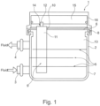
- the figure 1 shows a schematic representation of an electric heating device 1 with a housing 2.
- a Fluid inlet 3 and a fluid outlet 4 are provided, so that a fluid to be heated can flow through the fluid inlet into the housing, can flow through it and can be heated therein and can flow out of the housing 2 again through the fluid outlet 4 .
- Deflection means 5 can be provided in the housing 2, which deflect the fluid flow of the fluid to be heated in the housing 2 between the fluid inlet 3 and the fluid outlet 4 in order to bring about more favorable heating of the fluid to be heated with a suitable pressure drop.
- the deflection means 5 can be arranged as deflection walls, for example, in order to bring about a meandering fluid flow through the housing 2, for example.
- the housing 2 is designed in at least two parts, with a bottom 6 and a further housing part 7 being provided, which are tightly connected to one another.
- the base 6 can be positively connected to the housing part 7 and sealed. This can be done, for example, by a clamp connection or by a corrugated slot flanging by a mechanical connection.
- the base 6 can also be connected to the housing part 7 by soldering or welding or by gluing.
- Heating elements 9 protrude into the interior 13 of the housing and reach through openings 10 in the base 6, with the base 6 advantageously having a number of openings 10 as a wall, so that a corresponding number of heating elements 9 can protrude into the interior 13 of the housing 2 .
- the heating elements 9 are correspondingly inserted into the openings 10 of the base 6, the heating elements 9 being inserted into the base 6 in a sealing manner.
- the connection between the heating element 9 and the base 6 in the area of the openings 10 is made by welding and/or soldering.
- a heating element 9 has at least one heating element housing 11, in which at least one heating means 19 or a plurality of heating means 19 and the contact elements 12 making contact with the heating means 19 and electrical insulation 20 are arranged. At least two contact elements 12 are provided, which contact the heating element or elements 19 , the contact elements 12 being electrically insulated from the heating element housing 11 via the insulation 20 provided. In order to make contact with the contact elements 12 , they protrude from the heating element 9 or from the heating element housing 11 outside of the interior space 13 of the housing 2 from the heating element housing 11 .
- the heating elements 9 are inserted with their heating element housing 11 in a sealed manner into the openings 10 of the housing 2 in such a way that the housing 2 is sealed.
- the connection between the heater housing 11 and the housing 2 is sealed by a thermal bonding method such as welding and/or brazing. This creates a sealed, stable connection between the heating element housing 11 and the base 6 or the housing 2, so that the fluid can flow in the interior 13 of the housing 2 without the heating means 19 or the contact elements 12 coming into contact with the fluid .
- the heating elements 9 are correspondingly encapsulated, so that the heating element housing 11 is sealed off except for a passage 14 for the contact elements 12 . It is also preferred here if the contact elements 12 are guided through the passage 14 in a sealed manner. This can be done, for example, by the electrical insulation 20 provided or by an additional sealing element.
- the heating element housing 11 is formed from a tube which is open on one side, for example, to form the passage 14, the other side of the tube being sealed closed so that the closed portion of the tube can pass through the opening 10 in the base 6 into the Interior 13 of the housing 2 can protrude.
- the heating element housing 11 can be formed, for example, by a deep-drawn or extruded tube element, a welded or folded tube or by a tube manufactured in some other way.
- the heating element housing 11 can also be formed by a pocket which is formed, for example, from two shells, such as from two half-shells 52, 53.
- the formation of the heating element housing 11, for example by two shells, can preferably take place in that the two shells are thermally joined to one another at the edges, for example welded, soldered and/or glued, so that only the passage 14 for the contact elements 12 remains. It can also be advantageous if the passage 14 is also used for the insertion of the heating means 19, the contact elements 12 and the electrical insulation 20.
- the heating element or elements 19 and the contact elements 12 making contact with the at least one heating element 19 and the electrical insulation 20 are inserted into the heating element housing 11 as a preassembled unit.
- the preassembled unit can be prefabricated in order to be inserted into a heating element housing 11 provided.
- an electrical control unit 15 is provided according to the invention, which is electrically and/or mechanically connected to the contact elements 12 of the heating elements 9, so that the heating elements 9 can be controlled in a targeted manner.
- the electronic control unit 15 is connected to the floor 6 .
- the respective heating element 9 is encapsulated on its own, so that the respective heating element 9 protrudes into the interior space 13 of the housing 2 through which fluid flows. Since the respective heating elements 9 are thermally joined to the base 6, the current-carrying parts of the heating elements 9 are spatially and electrically or galvanically separated from the fluid flow. This is particularly advantageous for high-voltage applications with voltages greater than 60 volts.
- the base 6 and the heating element housing 11 are each prefabricated and connected to one another in a sealed manner by means of a thermal joining method, see above.
- the at least one heating means 19 with the contact elements 12 and the electrical insulation 20 can be inserted into the heating element housing 11, as pushed in, and the heating element housing 11 can be pressed, for example, for the positive connection of the components used, so that a favorable thermal contact of the elements is generated in the heater housing 11.
- the heating elements 9 can also be prefabricated and only then inserted into the openings in the base 6 and connected to the base 6 by a thermal joining method, for example.
- the heating element housing 11 can be produced, for example, by an extruded tube, an extruded part or a deep-drawn part. Alternatively, a welded tube or a folded tube can also be used, in which case after the introduction of the heating means 19, the contact elements 12 and the electrical insulation 20 the heating element housing 11 is pressed in order to improve the thermal contact between the heating means 19, the contact elements 12 and the insulation 20 with the heating element housing 11 in order to achieve a good heat transfer to the fluid to be heated.
- the heating element housing 11 can also be composed of two shells, such as two half-shells 52, 53, in which case the electrical insulation 20 with the heating means 19 and the contact elements 12 is inserted.
- the two shells 52, 53 can be connected to one another, for example, by thermal joining, ie welding, gluing or soldering.
- the shells are preferably joined to one another in a sealed manner at their edge.
- the shells or half-shells 52, 53 can also be joined mechanically, for example by flanging or deforming in some other way.
- the flow through the interior 13 of the housing 2 can be formed in a simple manner or with deflection of the fluid.
- the deflection means 5 can be provided for this purpose.
- the housing 2 can preferably be made of steel, aluminum or plastic and have a wall thickness of 1 to 4 mm, for example.
- the base 6 is preferably made of steel, aluminum or non-ferrous metal and advantageously has a material thickness of 0.5 to 3 mm.
- the heating element housing 11 is preferably made of steel, aluminum or non-ferrous metal and advantageously has a material thickness of 0.2 to 1 mm.
- the contact elements 12 are preferably designed as contact sheets made of aluminum or non-ferrous metal and advantageously have a material thickness of 0.2 to 1 mm.
- Alternative configurations of the housing 2, base 6, heating element housing 11 and/or contact element 12 can also have different dimensions or material thicknesses and materials.
- the electrical heating device 1 is preferably a high-voltage heating device for voltages of more than 60 volts or in particular of about 300 volts or more, with a large number of encapsulated heating elements 9, with a larger number of smaller encapsulated heating elements 9 or a smaller number of larger heating elements 9 being provided can.
- the elements of the heating elements 9 can be pushed into the heating element housing 11 and pressed or glued, or they can be inserted or glued into the shells or half-shells 52, 53, with the half-shells 52, 53 then being connected to one another in a sealed manner or beforehand, for example thermally be joined.
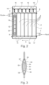
- the figure 2 shows an alternative embodiment of an electrical heating device 1 with a plurality of heating elements 9, which are arranged one after the other in the direction of flow of the fluid and optionally also in rows next to one another.
- the housing 2 is designed in several parts with a base 6, a further housing part 7, a lower housing cover 17 and a second base 18.
- the heating elements 9 can be inserted into the openings 10 of the base 6 and thermally joined and sealed, with the heating element housing 11 form a kind of tube matrix, which is arranged between the bases 6 and 18, the heating element housing being closed on one side and having a passage 14 for the contact elements 12 on the other side.
- the heating means 19 can also be seen as PTC elements, which are in electrical contact with the contact elements 12 on both sides, with the electrical insulation 20 being arranged around the contact elements 12 and the heating means 19 in order to prevent the combination of heating means 19 with contact elements 12 from the To insulate heating element housing 11 electrically.
- the control unit 15 is electrically connected to the contact elements 12, with the Control unit housing 16 is connected to the floor 6 in a mechanically sealed manner.
- PTC heating means can also be used instead of the PTC heating means. In principle, this also applies to all other exemplary embodiments in which PTC heating means or other heating means can be used.
- the figure 3 shows an embodiment of a heating element 50 in section with a heating element housing 51, which consists of two half-shells 52, 53, which are preferably thermally connected to one another, such as welded, soldered and/or glued.
- the half-shells 52, 53 have a passage 54 through which the contact elements 55 can protrude for electrical contacting, for example with a control unit.
- the heating element housing 51 In the heating element housing 51 are the heating means 56, on both sides of which the contact elements 55 and a peripheral electrical insulation 57 are arranged. Electrical insulation is generally solid, flexible, thin or thick insulation made of an electrically non-conductive insulating material.
- the figure 3 shows that the heating element is biconvex in section. In other exemplary embodiments, however, this can also be different, for example angular, rectangular, oval or round, etc.
- the biconvex shape is favorable for the pressure drop in the fluid.
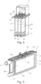
- the figure 4 shows another embodiment of an electric heater 1 similar to figure 1 in a partially sectioned view, the heating elements 9 with their heating element housings 11 being visible.
- the heating element housings 11 are inserted into the openings 10 of the base 6 at their upper end, with the contact elements 12 protruding from the heating elements 9 .
- the heating element housings 11 are designed as tubes that are closed on one side, with the heating means, the contact elements 12 and the electrical insulation 20 being inserted into the heating element housing 11 and the respective heating element housing then being pressed in the central area, so that there is favorable thermal contact between the elements of the heating element can be achieved with the heating element housing 11.
- the fluid to be heated can flow past the heating element housing on both sides in the direction of flow, so that a favorable flow guidance can be achieved.
- the tubes of the heating element housing are closed on the underside. This can be done by folding or by squeezing or by placing a closing element 21 or by welding, soldering or gluing.
- the openings 10 in the bottom 6 are designed as passages with a raised edge.
- the raised edge 23 can protrude into the interior 13 of the housing 2 or, as shown, point away from the interior 13 .
- the figure 5 shows an alternative electrical heating device 1, in which the heating elements 9 are designed as more flat elements, with the heating element housing 11 preferably being formed from shells, such as in particular half-shells 52, 53, so that the elements of the heating elements 9, i.e. the heating means 19 , the contact elements 12 and the electrical insulation 20 can be inserted into the shells or half-shells 52, 53 and glued, for example, with the two half-shells 52, 53 of the heating element housing 11 also being thermally joined at the edge 22, for example, such as being welded, soldered or glued in particular.
- the heating element housing 11 preferably being formed from shells, such as in particular half-shells 52, 53, so that the elements of the heating elements 9, i.e. the heating means 19 , the contact elements 12 and the electrical insulation 20 can be inserted into the shells or half-shells 52, 53 and glued, for example, with the two half-shells 52, 53 of the heating element housing 11 also being thermally joined at the edge 22, for example, such as being
- the design of the heating elements 9 is rather two-dimensional with a flat shape that shows a rectangular contour that almost fills the interior 13 of the housing 2 in the longitudinal direction.
- the heating elements 9 form a type of partition which causes a meandering flow through the housing 2 .
- the central heating element 9 bears against a rear wall of the housing 2 which is remote from the fluid inlet 3 and the fluid outlet 4 .
- the two outer heating elements 9 can, for example, also rest against the wall of the housing 2 in which the fluid inlet 3 and the fluid outlet 4 are arranged.
- the peripheral edge 22 of the heating element 9 runs almost completely, except for the passage 14, which is designed as an oval opening in order to lead the contact elements 12 out of the heating element 9 can.
- the passage 14 can also be designed in other ways and does not necessarily have to be oval in shape.
- the passages 14 of the adjacent heating elements 9 are offset from one another. The design of the passage 14 thus allows the heating elements 9 to come relatively close to one another transversely to the direction of flow of the fluid.
- FIGS. 4 and 5 show that an array of heating elements 9 can be formed in an adjacent array to each other.
- the heating elements 9 can be arranged in rows along and/or transversely to one another, ie in the direction of flow of the fluid or transversely thereto.
- the figure 6 shows schematically the arrangement of the elements of the heating elements 9, the heating means 19 and the contact elements 12 as well as the electrical insulation 20 being arranged in the circumferentially closed heating element housing 11.
- the electrical insulation 20 is formed by two insulating elements. It can also be formed by a single, for example, tube-like element.
- the heater housing 11 is rectangular in section. This can also be designed in other ways, such as round, oval, square, etc.
- the figure 7 shows an embodiment of an electric heating device 1 similar to FIG figure 2 , where the heating elements are 9 in figure 7 are arranged transversely to the direction of flow S between fluid inlet 3 and fluid outlet 4, while in figure 1 are arranged along the flow direction 5 between the fluid inlet 3 and the fluid outlet 4 .
- This means that the flow of the fluid to be heated between the fluid inlet 3 and the fluid outlet 4 in figure 2 preferably runs in a direction parallel to a plane between the fluid inlet and the fluid outlet, with the flow essentially parallel to the heating elements.
- the heating elements 9 are arranged essentially transversely to the direction of flow S between the fluid inlet 3 and the fluid outlet 4, so that a fluid flow also occurs essentially perpendicularly to a plane between the fluid inlet and the fluid outlet, i.e. between the heating elements 9, with the fluid being deflected at least twice, to be deflected starting from the fluid inlet 3, then to flow transversely between the heating elements 9 and then to be deflected again to the fluid outlet 4.
- the Figures 8 to 10 show an embodiment in which the heating elements 9 are viewed in two rows perpendicular to the direction of flow and in at least two columns are arranged one after the other in the direction of flow, so that a total of at least four or more heating elements 9 are arranged.
- the heating elements 9 are arranged within the housing 2, ie in two rows, with at least two or more heating elements 9 being able to be arranged in one row.
- a plurality of heating elements 9 can also be arranged in a row one after the other.
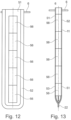
- the Figures 11 to 13 show details of heater housings 11 according to FIG figure 3 .
- the heating element housing 11 are formed in accordance with two shells 52, 53, according to figure 11 the electrical insulation 20 is designed as a molded part which almost completely encloses the contact elements 55 and the heating means 56, it being possible for one molded part or two molded parts to be provided as the electrical insulation 20.
- the half-shells 52, 53 have an edge 22 lying against one another, which is used to connect the half-shells 52, 53, for example by soldering, welding and/or gluing.
- the half-shells 52, 53 are also connected to the base 6 by thermal joining, for example by soldering, welding and/or gluing.
- the Figures 14 to 16 show another exemplary embodiment of an electrical heating device 1, in which several rows of heating means 19 are arranged in the heating elements 9 in the longitudinal direction of the heating element housing 11, the heating means 19 making electrical contact with one another via contact elements 12.
- the contact elements 12 can be provided for a row of heating means 19 , with the electrical insulation 20 electrically insulating the respective contact elements 12 from the heating element housing 11 .
- a few larger heating elements 9 are preferably provided, which are arranged, for example, in one to three stages.
- FIGS 17 to 19 show corresponding representations of heating devices 1, in which heating elements 9 are provided with a plurality of heating means 19. That's how they show Figures 19 and 20 that within a heating element 9, for example, three columns with five rows of heating means 19 are arranged. These can be contacted, for example, in columns or as a whole by individual or flat contact elements 12, so that, for example, only 1, 2 or 3 or a small number of such flat heating elements are arranged next to one another, in particular between fluid inlet 3 and fluid outlet 4. So that the heating means 19 are so geometric are arranged, auxiliary frames can be provided which position the heating means 19 in the heating element housing 11 . Other geometric arrangements of heating means in the heating element housing are also possible. Such geometric arrangements allow the heating means 19 to be evenly distributed over the surface in the heating element housing 11, so that the heating element housing 11 is heated evenly, particularly in the case of more extensive, more flat heating elements.
- Figures 21 to 23 Figure 1 shows alternative heating devices 1, in which three heating elements are arranged adjacent to each other, in each heating element two columns with six rows of heating means 19 are arranged.
- the heating means 19 of a heating element 9 are each contacted by flat contact elements 12 on one side, so that the heating elements can be controlled as a whole.
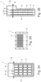
- the Figures 24 to 26 show an electrical heating device 1 with an electronic control unit 15, which contacts the contact elements 12 for controlling the heating means 19 for heating a fluid flowing through.
- the heating means 19 are arranged in rows and columns within a heating element 9, with three heating elements 9 being arranged next to one another and adjacent to one another.
- the respective heating element 9 can be switched on or off as a whole or can be controlled in terms of the heat output, or different groups of heating means 19 can be interconnected within a heating element 9 in order to effect finer control within a respective heating element 9 to be able to For example, each column of heating means 19 can be controlled individually.
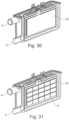
- FIGS. 27 to 31 show explanations accordingly figure 5 , wherein the heating means 19 according to figure 31 are arranged in rows and columns, the contact elements 12 according to figure 30 are flat elements that contact all heating means 19 of a heating element 9 .
- the heating means 19 of a heating element 9 can be controlled jointly via the control of the two opposing contact elements 12 . With the arrangement of three such heating elements 9, a corresponding control of the electrical heating device can be achieved.
- the heating device and/or the heating elements is/are tightly closed or encapsulated.
- a thermal joining method of the heating device and/or the heating elements can be used.
- the heating means can be designed as PTC elements. Alternatively, elements without a PTC effect can be used.
- the heating means are preferably energized via 2 contact elements as contact electrodes.
- the heating means are therefore arranged between two contact elements, such as contact electrodes.
- heating means 19 which are arranged between two sheet-like contact elements
- a heating means for example as Heating ceramics are used, which is provided with applied and / or printed resistance track or resistance tracks.
- This resistive track would then be electrically connected to achieve current flow.
- the resistance track would function as a contact element.
- a carrier material for example made of insulating ceramics and/or aluminum oxide with good thermal conductivity, is provided with applied resistance tracks as contact elements and contacted. The current then possibly does not flow over the short path from contact element to contact element, but over the long path over the length of the applied resistance track.
- the heating device can preferably be used for high-voltage applications.
- a trough with an essentially flat cover can also be provided.
- the electrical contacting of the heating elements is usually perpendicular to the direction of flow of the fluid to be heated.
- a rigid or flexible material or element such as a molded element or foil, can be used as electrical insulation.
- an arrangement of turbulence generators for increasing the output is also possible between the heating elements 9 and/or between the heating elements and the housing 2.
- the bottom 6 for receiving and arranging the heating elements is used in an advantageous embodiment, the direct contact Control unit with power electronics.
- the base 6 serves to close off the housing 2.
- the base 6 is used to fasten and seal the control unit or the power electronics and to seal the housing 2 through which fluid flows.
- the nominal electrical power of the heating device 1 can be in the range from 3 kW to about 9 kW, preferably about 5 kW.
Description
Die Erfindung betrifft eine elektrische Heizeinrichtung, insbesondere zur Beheizung eines Innenraums eines Kraftfahrzeugs.The invention relates to an electrical heating device, in particular for heating an interior of a motor vehicle.
Kraftfahrzeuge weisen üblicherweise einen beheizbaren Innenraum auf. Dazu weisen Kraftfahrzeuge mit Verbrennungsmotor üblicherweise einen im Kühlkreislauf angeschlossenen Heizungswärmeübertrager auf, durch welchen heißes Kühlmittel strömt, das vom Verbrennungsmotor erwärmt wird. Dadurch kann die durch den Heizungswärmeübertrager strömende Luft erwärmt und dem Innenraum zugeführt werden.Motor vehicles usually have a heatable interior. For this purpose, motor vehicles with an internal combustion engine usually have a heating heat exchanger connected in the cooling circuit, through which hot coolant flows, which is heated by the internal combustion engine. As a result, the air flowing through the heating heat exchanger can be heated and fed to the interior.
Insbesondere Kraftfahrzeuge mit verbrauchsarmen Verbrennungsmotoren, die weniger Abwärme erzeugen, und Kraftfahrzeuge mit Plug-In/Range Extender benötigen für die Innenraumbeheizung Zuheizeinrichtungen. Kraftfahrzeuge mit Elektroantrieb benötigen Heizeinrichtungen, da eine Erwärmung mit vom Verbrennungsmotor erwärmtem Kühlmittel ausfällt, weil sie keinen Verbrennungsmotor aufweisen.In particular, motor vehicles with fuel-efficient internal combustion engines that generate less waste heat and motor vehicles with plug-in/range extenders require auxiliary heating devices for interior heating. Motor vehicles with electric drives require heating devices, since heating with coolant heated by the internal combustion engine fails because they do not have an internal combustion engine.
Dabei ist vor allem in der Startphase und/oder bei geringen Außentemperaturen ein Zuheizen bzw. ein Heizen erwünscht oder notwendig.In this case, additional heating or heating is desirable or necessary, especially in the starting phase and/or at low outside temperatures.
Hierfür sind verschiedene Heizeinrichtungen bzw. Zuheizeinrichtungen bekannt geworden, wie beispielsweise elektrische Zuheizeinrichtungen, Wärmepumpeneinrichtungen, Brennstoffheizer, sowie eine Zuheizung mittels Abgas-Wärmeübertragern.Various heating devices or auxiliary heating devices have become known for this purpose, such as electrical auxiliary heating devices, heat pump devices, fuel heaters, and auxiliary heating by means of exhaust gas heat exchangers.
Die elektrische Zuheizung hat den Vorteil, dass die dafür notwendigen elektrischen Heizeinrichtungen relativ kostengünstig sind im Vergleich zu anderen Lösungen und dass die erzeugte Wärme relativ spontan spürbar ist, weil die elektrische Leistung quasi sofort in spürbare Wärme umgesetzt wird. Weiterhin sind elektrische Heizeinrichtungen platzsparend und damit in einem Kraftfahrzeug flexibel einbaubar.The electrical auxiliary heating has the advantage that the electrical heating devices required for this are relatively inexpensive compared to other solutions and that the heat generated can be felt relatively spontaneously because the electrical power is converted almost immediately into noticeable heat. Furthermore, electrical heating devices are space-saving and can therefore be installed flexibly in a motor vehicle.
Für hybridisierte Fahrzeuge oder rein elektrisch betriebene Fahrzeuge ist der Stellenwert der elektrischen Heizung bzw. Zuheizung noch größer, da eine Erwärmung über Abwärme des Verbrennungsmotors nicht möglich ist. Bei solchen Kraftfahrzeugen werden elektrische Leistungen von etwa mehr als 3kW benötigt. Dies bedeutet auch, dass eine hohe Leistungsdichte vorteilhaft ist. Bei solchen Kraftfahrzeugen liegt die Bordnetzspannung meist über 60 Volt, teilweise sogar über 300V. Aufgrund der hohen geforderten Heizleistungen am (Zu-)Heizer wird auch diese elektrische Heizeinrichtung mit der hohen Spannung betrieben, um die im Betrieb auftretende Stromstärke möglichst gering zu halten.For hybridized vehicles or purely electrically operated vehicles, the importance of electric heating or auxiliary heating is even greater, since it is not possible to heat the vehicle using waste heat from the combustion engine. In such motor vehicles, electrical power of about more than 3 kW is required. This also means that high power density is beneficial. In such motor vehicles, the vehicle electrical system voltage is usually over 60 volts, sometimes even over 300V. Due to the high heating power required at the (additional) heater, this electrical heating device is also operated with high voltage in order to keep the current intensity that occurs during operation as low as possible.
Ein solcher Heizer bzw. Zuheizer als Heizeinrichtung für Hochvoltanwendungen, also für Spannungen über 60 Volt, muss so ausgebildet sein, dass eine Gefährdung durch die Heizeinrichtung im Betrieb oder bei einer Wartung ausgeschlossen werden kann.Such a heater or auxiliary heater as a heating device for high-voltage applications, ie for voltages over 60 volts, must be designed in such a way that a hazard from the heating device during operation or maintenance can be ruled out.
Bei den elektrischen Heizeinrichtungen als Zuheizer oder als alleinige Heizer gibt es grundsätzlich die Möglichkeit, dass die elektrische Leistung direkt in ein flüssiges Medium, wie beispielsweise ein Kühlmittel, geleitet wird, welches über einen weiteren Wärmetauscher die Wärme in den Innenraum des Kraftfahrzeugs abgibt. Eine solche Heizeinrichtung wird auch als kühlmittelseitige Heizeinrichtung bezeichnet.In the case of electrical heating devices as auxiliary heaters or as sole heaters, there is basically the possibility that the electrical power is fed directly into a liquid medium, such as a coolant, which emits the heat into the interior of the motor vehicle via a further heat exchanger. Such a heating device is also referred to as a coolant-side heating device.
Auch gibt es die Möglichkeit, dass die elektrische Leistung an die Luft abgegeben wird und diese erwärmte Luft für die Beheizung des Innenraums herangezogen wird. Eine solche Heizeinrichtung wird auch als luftseitige Heizeinrichtung bezeichnet.There is also the possibility that the electrical power is released into the air and this heated air is used to heat the interior. Such a heating device is also referred to as an air-side heating device.
Die luftseitigen Heizeinrichtungen sind zeitlich spontaner, da die elektrische Energie zu nahezu hundert Prozent in Lufterwärmung umgesetzt wird. Der Wirkungsgrad liegt bei nahezu hundert Prozent. Er kann sinnvollerweise jedoch nur zur Erwärmung des Innenraumes der Fahrzeugkabine eingesetzt werden. Ebenso ist er sinnvollerweise im Fahrzeuginnenraum, also im Klimagerät, integriert. Die Integration einer Hochspannungskomponente im Innenraum ist sicherheitsbedingt jedoch aufwendig und bedeutet in der Regel eine aufwändigere Konstruktion des Klimageräts, was die Kosten erhöht.The air-side heating devices are more spontaneous in terms of time, since almost one hundred percent of the electrical energy is converted into air heating. The efficiency is almost one hundred percent. However, it can only be used to heat the interior of the vehicle cabin. It is also usefully integrated in the vehicle interior, i.e. in the air conditioning unit. However, the integration of a high-voltage component in the interior is complex for safety reasons and generally means a more complex construction of the air conditioning unit, which increases the costs.
Die kühlmittelseitige Heizeinrichtung ist in ihrer Heizwirkung nicht ganz so spontan und effizient, da die elektrische Energie erst genutzt wird, um das Fluid, beispielsweise in einem kleinen Wasserkreislauf, aufzuwärmen. An einem separaten Kühlmittel/Luft-Wärmeübertrager, wie bei einem Kraftfahrzeug mit Verbrennungsmotor, wird das erwärmte Fluid bzw. Wasser genutzt, um die in den Innenraum einströmende Luft zu erwärmen.The heating device on the coolant side is not quite as spontaneous and efficient in its heating effect, since the electrical energy is first used to warm up the fluid, for example in a small water circuit. The heated fluid or water is used in a separate coolant/air heat exchanger, as in a motor vehicle with an internal combustion engine, to heat the air flowing into the interior.
Es befindet sich dabei vorzugsweise keine Hochspannungskomponente im Innenraum des Kraftfahrzeugs. Auch ist es bei dieser Konstellation vorteilhaft, dass die kühlmittelseitige Heizeinrichtung an verschiedenen Stellen außerhalb des Innenraums im Kraftfahrzeug angebracht werden kann. Das Klimagerät kann wie bei einem klassischen Kraftfahrzeug genutzt werden, ohne dass große konstruktive Änderungen notwendig werden. Ein weiterer Vorteil der kühlmittelseitigen Heizeinrichtung ist die Möglichkeit, eine Batterie beispielsweise bei einem reinen Elektrofahrzeug durch das warme Wasser bzw. durch das Kühlmittel mit zu beheizen bzw. aufwärmen zu können.There is preferably no high-voltage component in the interior of the motor vehicle. It is also advantageous in this constellation that the coolant-side heating device is outside at various points of the interior can be mounted in the motor vehicle. The air conditioning unit can be used like in a classic motor vehicle without major design changes being necessary. A further advantage of the coolant-side heating device is the possibility of being able to also heat or warm up a battery, for example in the case of a purely electric vehicle, by the warm water or by the coolant.
Im Stand der Technik sind verschiedene kühlmittelseitige Heizeinrichtungen bekannt geworden. Die
Es sind auch Heizeinrichtungen mit PTC-Heizelementen bekannt, die mittels Kontaktelektroden bestromt werden, siehe die
Die Heizeinrichtungen gemäß dem Stand der Technik weisen dabei auch Nachteile auf.The heating devices according to the prior art also have disadvantages.
Die kühlmittelseitigen Widerstandsheizer weisen keine Eigensicherheit der Heizeinheit bezüglich einer Temperaturüberhöhung auf. Daher ist eine Temperaturüberwachung und eine entsprechende Abschaltung notwendig, beispielsweise bei einem plötzlichen Stillstand des Kühlmittelvolumenstroms. Die kühlmittelseitigen PTC-Heizeinrichtungen weisen üblicherweise eine hohe Anzahl an Heizeinheiten auf, die aus 2 Kontaktelektroden und PTC-Heizelementen und Isolationen bestehen. Dadurch resultiert ein eher hoher Montageaufwand. Durch die Gussgehäuse resultieren schwere und große Ausführungen.The resistance heaters on the coolant side do not have any intrinsic safety of the heating unit with regard to excessive temperatures. It is therefore necessary to monitor the temperature and switch it off accordingly, for example if the coolant volume flow suddenly stops. The coolant-side PTC heating devices usually have a large number of heating units, which consist of 2 contact electrodes and PTC heating elements and insulation. This results in a rather high assembly effort. The cast housing results in heavy and large designs.
Es ist die Aufgabe der Erfindung, eine elektrische Heizeinrichtung zu schaffen, die gegenüber dem Stand der Technik einfach und kostengünstig herzustellen ist und dennoch gegenüber dem Stand der Technik verbessert ist.It is the object of the invention to provide an electrical heating device which is simple and inexpensive to produce compared to the prior art and is nevertheless improved compared to the prior art.
Die Aufgabe wird mit den Merkmalen von Anspruch 1 gelöst.The object is solved with the features of
Die Erfindung betrifft eine elektrische Heizeinrichtung mit einem Gehäuse mit einem Fluideinlass und mit einem Fluidauslass, wobei in einer Wandung eine Anzahl von Öffnungen vorgesehen ist, in welche Heizelemente eingesetzt und in den Innenraum des Gehäuses ragen, wobei die Heizelemente ein Heizelementgehäuse aufweisen und wobei ein Heizelement in dem Heizelementgehäuse zumindest ein Heizmittel und das zumindest eine Heizmittel kontaktierende Kontaktelemente und eine elektrische Isolierung zur Isolierung der Kontaktelemente gegenüber dem Heizelementgehäuse aufweist, wobei die Kontaktelemente insbesondere aus dem Heizelement herausragen und wobei die Heizelemente mit ihrem Heizelementgehäuse derart in die Öffnungen des Gehäuses eingesetzt sind, dass die Heizelementgehäuse mit dem Gehäuse abdichtend verbunden sind. Dadurch kann das jeweilige Heizelement in das Gehäuse hineinragen, das von dem zu erwärmenden Fluid durchströmt wird, wobei dennoch eine einfache und kostengünstige Bauweise erzielt ist.The invention relates to an electrical heating device having a housing with a fluid inlet and a fluid outlet, with a number of openings being provided in a wall, into which heating elements are inserted and protruding into the interior of the housing, the heating elements having a heating element housing and a The heating element in the heating element housing has at least one heating means and the contact elements that make contact with at least one heating means and electrical insulation for insulating the contact elements from the heating element housing, the contact elements protruding in particular from the heating element and the heating elements with their heating element housing being inserted into the openings of the housing in this way , that the heating element housing are sealingly connected to the housing. As a result, the respective heating element can protrude into the housing through which the fluid to be heated flows, with a simple and cost-effective construction nevertheless being achieved.
Gemäß der Erfindung ist das Heizelementgehäuse mit dem Gehäuse durch ein thermisches Verbindungsverfahren abgedichtet verbunde n, wie durch Schweißen und/oder Löten verbunde n.In accordance with the invention, the heater housing is sealed to the housing by a thermal bonding method, such as by welding and/or brazing.
Dadurch wird erreicht, dass die Verbindung zwischen dem Heizelementgehäuse und dem Gehäuse stabil und dauerhaft dicht ist, um die notwendige Betriebssicherheit zu erreichen.This ensures that the connection between the heating element housing and the housing is stable and permanently sealed in order to achieve the necessary operational reliability.
Auch ist es vorteilhaft, wenn die Heizelemente derart gekapselt sind, dass das Heizelementgehäuse bis auf einen Durchgang für die Kontaktelemente abgedichtet verschlossen ist. Dadurch ist das Heizelementgehäuse nach außen hin zum zu erwärmenden Fluid dicht ausgebildet und dennoch können die Kontaktelemente aus dem Heizelementgehäuse heraus geführt werden, um die Bestromung der Heizmittel vorzunehmen. Die Kontaktelemente sind dabei allerdings von dem zu erwärmenden Fluid getrennt und abgedichtet angeordnet.It is also advantageous if the heating elements are encapsulated in such a way that the heating element housing is sealed except for a passage for the contact elements. As a result, the heating element housing is designed to be sealed to the outside with respect to the fluid to be heated, and the contact elements can nevertheless be guided out of the heating element housing in order to carry out the energization of the heating means. However, the contact elements are separated from the fluid to be heated and arranged in a sealed manner.
Auch ist es vorteilhaft, wenn die Kontaktelemente in dem Durchgang abgedichtet durchgeführt sind. So wird erreicht, dass auch versehentlich auftretendes Fluid im Bereich der Kontaktelemente nicht in das Heizelement eindringen kann.It is also advantageous if the contact elements are carried out in a sealed manner in the passage. In this way it is achieved that even accidentally occurring fluid in the area of the contact elements cannot penetrate into the heating element.
Besonders vorteilhaft ist es auch, wenn das Heizelementgehäuse aus einem einseitig offenen Rohr, einem tiefgezogenen oder fließgepressten Rohrelement oder aus zwei Schalen, wie Halbschalen gebildet ist. Dadurch kann erreicht werden, dass das Heizelementgehäuse quasi umseitig geschlossen ist und nur für den Durchgang der Kontaktelemente eine Öffnung aufweist.It is also particularly advantageous if the heating element housing is formed from a tube that is open on one side, a deep-drawn or extruded tube element, or from two shells, such as half-shells. It can thereby be achieved that the heating element housing is more or less closed on the other side and has an opening only for the passage of the contact elements.
Bei einem Ausführungsbeispiel ist es vorteilhaft, wenn das zumindest eine Heizmittel und die das zumindest eine Heizmittel kontaktierenden Kontaktelemente und die elektrische Isolierung in das Heizelementgehäuse als vormontierte Einheit eingesetzt sind. Dadurch kann die Montage erheblich vereinfacht werden und es entstehen weniger Fehler durch beispielsweise eine nicht richtig ausgeführte Isolation. Nach dem Einsetzen kann dann beispielsweise auch das Heizelementgehäuse verdrückt oder verformt werden, um die eingesetzten Elemente bzw. die vormontierte Einheit darin formschlüssig zu halten.In one exemplary embodiment, it is advantageous if the at least one heating means and the contact elements that make contact with the at least one heating means and the electrical insulation are inserted into the heating element housing as a preassembled unit. As a result, assembly can be considerably simplified and there are fewer errors, for example due to improper insulation. After insertion, the heating element housing can then also be pressed or deformed, for example, in order to hold the elements used or the preassembled unit therein in a form-fitting manner.
Gemäß der Erfindung ist das Gehäuse zumindest zweiteilig ausgebildet, und das Gehäuse aus einem Boden mit den Öffnungen zur Aufnahme der Heizelemente und aus zumindest einem weiteren Gehäuseteil besteht. Dadurch kann die Heizeinrichtung einfacher hergestellt sein, beispielsweise durch Tiefziehen einzelner Gehäuseteile des Gehäuses, wobei die Gehäuseteile des Gehäuses anschließend abgedichtet miteinander verbunden werden, um den fluiddurchströmten Innenraum abzudichten. Dies kann beispielsweise durch Löten, Schweißen oder Kleben erfolgen oder durch Anordnung einer Dichtung und durch ein Vercrimpen oder durch eine Wellschlitzbördelung.According to the invention, the housing is designed in at least two parts, and the housing consists of a base with the openings for receiving the heating elements and at least one further housing part. As a result, the heating device can be manufactured more simply, for example by deep-drawing individual housing parts of the housing, the housing parts of the housing then being connected to one another in a sealed manner in order to seal off the interior space through which the fluid flows. This can be done, for example, by soldering, welding or gluing, or by arranging a seal and by crimping or by flanging a corrugated slot.
Gemäß der Erfindung ist das Gehäuse zumindest zweiteilig ausgebildet und das Gehäuse aus einem Boden mit den Öffnungen zur Aufnahme der Heizelemente und aus zumindest einem weiteren Gehäuseteil besteht. Dabei kann der Boden eben ausgebildet sein und das andere Gehäuseteil kann wannenartig ausgebildet sein. Auch kann der Boden gewölbt sein, wie beispielsweise wannenförmig. In diesem Fall könnte das andere Gehäuseteil auch eben ausgebildet sein.According to the invention, the housing is designed in at least two parts and the housing consists of a base with the openings for receiving the heating elements and at least one further housing part. The bottom can be flat and the other housing part can be trough-like. The bottom can also be curved, for example trough-shaped. In this case, the other housing part could also be flat.
Gemäß der Erfindung ist weiterhin eine elektronische Steuereinheit vorgesehen, welche die Kontaktelemente der Heizelemente kontaktiert, wobei die Steuereinheit mit dem Boden verbunden ist. Dadurch kann die Heizeinrichtung mit elektronischer Steuereinheit als Baueinheit kompakt hergestellt und gemeinsam im Kraftfahrzeug verbaut werden, beispielsweise im Motorraum.According to the invention, an electronic control unit is also provided which contacts the contact elements of the heating elements, the control unit being connected to the ground. As a result, the heating device with the electronic control unit can be manufactured compactly as a structural unit and installed together in the motor vehicle, for example in the engine compartment.
Für einen verbesserten Wärmeübergang und einen angepassten Druckabfall des zu erwärmenden Fluids ist es vorteilhaft, wenn in dem Gehäuse Umlenkmittel vorgesehen sind, welche einen Fluidstrom zwischen dem Fluideinlass und dem Fluidauslass umlenken. Dadurch wird der Strömungspfad des zu erwärmenden Fluids umgelenkt und insbesondere auch verlängert, um einen verbesserten Wärmeübergang bei akzeptablem Druckabfall zu erreichen.For improved heat transfer and an adapted pressure drop of the fluid to be heated, it is advantageous if deflection means are provided in the housing, which deflect a fluid flow between the fluid inlet and the fluid outlet. As a result, the flow path of the fluid to be heated is deflected and, in particular, also lengthened in order to achieve improved heat transfer with an acceptable pressure drop.
Auch ist es vorteilhaft, wenn das zumindest eine Heizmittel mit den kontaktierenden Kontaktelementen flächig verbunden ist.It is also advantageous if the at least one heating means is connected over a large area to the contacting contact elements.
Ebenso ist es zweckmäßig, wenn das zumindest eine Heizmittel ein PTC-Element aufweist oder ist.It is also expedient if the at least one heating means has or is a PTC element.
Weitere vorteilhafte Ausgestaltungen sind durch die nachfolgende Figurenbeschreibung und durch die Unteransprüche beschrieben.Further advantageous configurations are described by the following description of the figures and by the dependent claims.
Nachstehend wird die Erfindung auf der Grundlage mehrerer Ausführungsbeispiele anhand der Figuren der Zeichnungen näher erläutert. Es zeigen:
- Fig. 1
- eine schematische Schnittdarstellung eines Ausführungsbeispiels einer erfindungsgemäßen elektrischen Heizvorrichtung,
- Fig. 2
- eine schematische Schnittdarstellung eines weiteren Ausführungsbeispiels einer erfindungsgemäßen elektrischen Heizvorrichtung,
- Fig. 3
- eine Darstellung eines Schnitts durch ein Heizelement,
- Fig. 4
- eine schematische Teildarstellung eines weiteren Ausführungsbeispiels einer erfindungsgemäßen elektrischen Heizvorrichtung,
- Fig. 5
- eine schematische Teildarstellung eines weiteren Ausführungsbeispiels einer erfindungsgemäßen elektrischen Heizvorrichtung,
- Fig. 6
- eine Darstellung eines Schnitts durch ein Heizelement,
- Fig. 7
- eine schematische Schnittdarstellung eines weiteren Ausführungsbeispiels einer erfindungsgemäßen elektrischen Heizvorrichtung,
- Fig. 8
- eine schematische Teildarstellung eines weiteren Ausführungsbeispiels einer erfindungsgemäßen elektrischen Heizvorrichtung,
- Fig. 9
- eine schematische Teildarstellung eines weiteren Ausführungsbeispiels einer erfindungsgemäßen elektrischen Heizvorrichtung,
- Fig. 10
- eine schematische Teildarstellung eines weiteren Ausführungsbeispiels einer erfindungsgemäßen elektrischen Heizvorrichtung,
- Fig. 11
- eine Darstellung eines Schnitts durch ein Heizelement,
- Fig. 12
- eine Darstellung eines Schnitts durch ein Heizelement,
- Fig. 13
- eine Darstellung eines Schnitts durch ein Heizelement,
- Fig. 14
- eine schematische Teildarstellung eines weiteren Ausführungsbeispiels einer erfindungsgemäßen elektrischen Heizvorrichtung,
- Fig. 15
- eine schematische Teildarstellung eines weiteren Ausführungsbeispiels einer erfindungsgemäßen elektrischen Heizvorrichtung,
- Fig. 16
- eine Darstellung eines Schnitts durch ein Heizelement,
- Fig. 17
- eine schematische Teildarstellung eines weiteren Ausführungsbeispiels einer erfindungsgemäßen elektrischen Heizvorrichtung,
- Fig. 18
- eine schematische Teildarstellung eines weiteren Ausführungsbeispiels einer erfindungsgemäßen elektrischen Heizvorrichtung,
- Fig. 19
- eine schematische Teildarstellung eines weiteren Ausführungsbeispiels einer erfindungsgemäßen elektrischen Heizvorrichtung,
- Fig. 20
- eine schematische Teildarstellung eines weiteren Ausführungsbeispiels einer erfindungsgemäßen elektrischen Heizvorrichtung,
- Fig. 21
- eine schematische Schnittdarstellung eines weiteren Ausführungsbeispiels einer erfindungsgemäßen elektrischen Heizvorrichtung,
- Fig. 22
- eine schematische Schnittdarstellung eines weiteren Ausführungsbeispiels einer erfindungsgemäßen elektrischen Heizvorrichtung,
- Fig. 23
- eine schematische Schnittdarstellung eines weiteren Ausführungsbeispiels einer erfindungsgemäßen elektrischen Heizvorrichtung,
- Fig. 24
- eine schematische Schnittdarstellung eines weiteren Ausführungsbeispiels einer erfindungsgemäßen elektrischen Heizvorrichtung,
- Fig. 25
- eine schematische Schnittdarstellung eines weiteren Ausführungsbeispiels einer erfindungsgemäßen elektrischen Heizvorrichtung,
- Fig. 26
- eine schematische Schnittdarstellung eines weiteren Ausführungsbeispiels einer erfindungsgemäßen elektrischen Heizvorrichtung,
- Fig. 27
- eine schematische Teildarstellung eines weiteren Ausführungsbeispiels einer erfindungsgemäßen elektrischen Heizvorrichtung,
- Fig. 28
- eine schematische Teildarstellung eines weiteren Ausführungsbeispiels einer erfindungsgemäßen elektrischen Heizvorrichtung,
- Fig. 29
- eine Darstellung eines Schnitts durch ein Heizelement,
- Fig. 30
- eine schematische Teildarstellung eines weiteren Ausführungsbeispiels einer erfindungsgemäßen elektrischen Heizvorrichtung, und
- Fig. 31
- eine schematische Teildarstellung eines weiteren Ausführungsbeispiels einer erfindungsgemäßen elektrischen Heizvorrichtung.
- 1
- a schematic sectional view of an embodiment of an electrical heating device according to the invention,
- 2
- a schematic sectional view of a further embodiment of an electrical heating device according to the invention,
- 3
- a representation of a section through a heating element,
- 4
- a schematic partial representation of a further embodiment of an electrical heating device according to the invention,
- figure 5
- a schematic partial representation of a further embodiment of an electrical heating device according to the invention,
- 6
- a representation of a section through a heating element,
- 7
- a schematic sectional view of a further embodiment of an electrical heating device according to the invention,
- 8
- a schematic partial representation of a further embodiment of an electrical heating device according to the invention,
- 9
- a schematic partial representation of a further embodiment of an electrical heating device according to the invention,
- 10
- a schematic partial representation of a further embodiment of an electrical heating device according to the invention,
- 11
- a representation of a section through a heating element,
- 12
- a representation of a section through a heating element,
- 13
- a representation of a section through a heating element,
- 14
- a schematic partial representation of a further embodiment of an electrical heating device according to the invention,
- 15
- a schematic partial representation of a further embodiment of an electrical heating device according to the invention,
- 16
- a representation of a section through a heating element,
- 17
- a schematic partial representation of a further embodiment of an electrical heating device according to the invention,
- 18
- a schematic partial representation of a further embodiment of an electrical heating device according to the invention,
- 19
- a schematic partial representation of a further embodiment of an electrical heating device according to the invention,
- 20
- a schematic partial representation of a further embodiment of an electrical heating device according to the invention,
- 21
- a schematic sectional view of a further embodiment of an electrical heating device according to the invention,
- 22
- a schematic sectional view of a further embodiment of an electrical heating device according to the invention,
- 23
- a schematic sectional view of a further embodiment of an electrical heating device according to the invention,
- 24
- a schematic sectional view of a further embodiment of an electrical heating device according to the invention,
- 25
- a schematic sectional view of a further embodiment of an electrical heating device according to the invention,
- 26
- a schematic sectional view of a further embodiment of an electrical heating device according to the invention,
- 27
- a schematic partial representation of a further embodiment of an electrical heating device according to the invention,
- 28
- a schematic partial representation of a further embodiment of an electrical heating device according to the invention,
- 29
- a representation of a section through a heating element,
- 30
- a schematic partial representation of a further embodiment of an electrical heating device according to the invention, and
- 31
- a schematic partial representation of a further embodiment of an electrical heating device according to the invention.
Die
Die
Das Gehäuse 2 ist gemäß der Erfindung zumindest zweiteilig ausgebildet, wobei ein Boden 6 und ein weiteres Gehäuseteil 7 vorgesehen sind, welche dicht miteinander verbunden sind. Dabei kann beispielsweise unter Zwischenlage einer Dichtung 8 der Boden 6 mit dem Gehäuseteil 7 formschlüssig verbunden und abgedichtet sein. Dies kann beispielsweise durch eine Klemmverbindung oder durch eine Wellschlitzbördelung durch eine mechanische Verbindung erfolgen. Alternativ dazu kann der Boden 6 mit dem Gehäuseteil 7 auch durch Löten oder Schweißen oder durch Verkleben miteinander verbunden sein.According to the invention, the
In den Innenraum 13 des Gehäuses ragen Heizelemente 9, welche durch Öffnungen 10 im Boden 6 hindurchgreifen, wobei der Boden 6 als Wandung vorteilhaft eine Anzahl von Öffnungen 10 aufweist, so dass eine entsprechende Anzahl von Heizelementen 9 in den Innenraum 13 des Gehäuses 2 ragen kann. Die Heizelemente 9 sind entsprechend in die Öffnungen 10 des Bodens 6 eingesetzt, wobei die Heizelemente 9 in den Boden 6 abdichtend eingesetzt sind. Die Verbindung zwischen Heizelement 9 und Boden 6 im Bereich der Öffnungen 10 erfolgt durch Schweißen und/oder Löten.
Ein Heizelement 9 weist zumindest ein Heizelementgehäuse 11 auf, in welchem zumindest ein Heizmittel 19 oder eine Mehrzahl von Heizmitteln 19 und das oder die Heizmittel 19 kontaktierende Kontaktelemente 12 und eine elektrische Isolierung 20 angeordnet sind. Dabei sind zumindest zwei Kontaktelemente 12 vorgesehen, welche das oder die Heizmittel 19 kontaktieren, wobei die Kontaktelemente 12 über die vorgesehene Isolierung 20 gegenüber dem Heizelementgehäuse 11 elektrisch isoliert sind. Zur Kontaktierung der Kontaktelemente 12 ragen diese aus dem Heizelement 9 bzw. aus dem Heizelementgehäuse 11 außerhalb des Innenraums 13 des Gehäuses 2 aus dem Heizelementgehäuse 11 heraus.A
Die Heizelemente 9 sind mit ihrem Heizelementgehäuse 11 dabei derart in die Öffnungen 10 des Gehäuses 2 abgedichtet eingesetzt, dass das Gehäuse 2 abgedichtet ist. Die Verbindung zwischen dem Heizelementgehäuse 11 und dem Gehäuse 2 ist durch ein thermisches Verbindungsverfahren abgedichtet, wie wie durch Schweißen und/oder Löten. Dadurch wird eine abgedichtete stabile Verbindung zwischen dem Heizelementgehäuse 11 und dem Boden 6 bzw. dem Gehäuse 2 bewirkt, so dass das Fluid im Innenraum 13 des Gehäuses 2 strömen kann, ohne dass das Heizmittel 19 bzw. die Kontaktelemente 12 mit dem Fluid in Kontakt treten. Die Heizelemente 9 sind entsprechend gekapselt, so dass das Heizelementgehäuse 11 bis auf einen Durchgang 14 für die Kontaktelemente 12 abgedichtet verschlossen ist. Dabei ist es auch bevorzugt, wenn die Kontaktelemente 12 in dem Durchgang 14 abgedichtet durchgeführt sind. Dies kann beispielsweise durch die vorgesehene elektrische Isolierung 20 oder durch ein zusätzliches Dichtelement erfolgen.The
Bevorzugt ist das Heizelementgehäuse 11 aus einem Rohr ausgebildet, welches beispielsweise einseitig offen ist, um den Durchgang 14 auszubilden, wobei die andere Seite des Rohrs abgedichtet geschlossen ist, so dass der geschlossene Bereich des Rohrs durch die Öffnung 10 im Boden 6 in den Innenraum 13 des Gehäuses 2 hineinragen kann. Das Heizelementgehäuse 11 kann beispielsweise durch ein tiefgezogenes oder fließgepresstes Rohrelement, ein geschweißtes oder gefalztes Rohr oder anderweitig durch ein anderweitig hergestelltes Rohr ausgebildet sein.Preferably, the
Alternativ kann das Heizelementgehäuse 11 auch durch eine Tasche gebildet sein, die beispielsweise aus zwei Schalen, wie beispielsweise aus zwei Halbschalen 52, 53, gebildet ist. Die Ausbildung des Heizelementgehäuses 11, beispielsweise durch zwei Schalen, kann bevorzugt dadurch erfolgen, dass die beiden Schalen randseitig miteinander thermisch gefügt sind, wie beispielsweise geschweißt, gelötet und/oder verklebt sind, so dass lediglich der Durchgang 14 für die Kontaktelemente 12 verbleibt. Dabei kann es auch vorteilhaft sein, wenn der Durchgang 14 auch für das Einsetzen der Heizmittel 19, der Kontaktelemente 12 und der elektrischen Isolierung 20 dient.Alternatively, the
Besonders bevorzugt ist es, wenn das oder die Heizmittel 19 und die das zumindest eine Heizmittel 19 kontaktierenden Kontaktelemente 12 und die elektrische Isolierung 20 in das Heizelementgehäuse 11 als vormontierte Einheit eingesetzt sind. Dazu kann die vormontierte Einheit vorgefertigt werden, um in ein bereitgestelltes Heizelementgehäuse 11 eingesetzt zu werden.It is particularly preferred if the heating element or
Zur Steuerung der elektrischen Heizeinrichtung 1 ist erfindungsgemäß eine elektrische Steuereinheit 15 vorgesehen, welche mit den Kontaktelementen 12 der Heizelemente 9 elektrisch und/oder mechanisch verbunden ist, so dass eine gezielte Steuerung der Heizelemente 9 erfolgen kann.To control the
Die elektronische Steuereinheit 15 ist mit dem Boden 6 verbunden.The
Dadurch kann eine Baueinheit geschaffen werden, die es erlaubt, im Kraftfahrzeug bauraumabhängig angeordnet zu werden.As a result, a structural unit can be created which allows it to be arranged in the motor vehicle depending on the installation space.
In einem Ausführungsbeispiel der erfindungsgemäßen Heizeinrichtung ist das jeweilige Heizelement 9 für sich gekapselt, so dass das jeweilige Heizelement 9 in den Fluid durchströmten Innenraum 13 des Gehäuses 2 hineinragt. Da die jeweiligen Heizelemente 9 mit dem Boden 6 thermisch gefügt sind, sind die stromführenden Teile der Heizelemente 9 vom Fluidstrom räumlich und elektrisch bzw. galvanisch getrennt. Insbesondere bei Hochvoltanwendungen mit Spannungen von größer als 60 Volt ist dies vorteilhaft.In an exemplary embodiment of the heating device according to the invention, the
In der Herstellung kann es vorteilhaft sein, wenn der Boden 6 und das Heizelementgehäuse 11 jeweils vorgefertigt werden und mittels eines thermischen Fügeverfahrens, siehe oben, miteinander abgedichtet verbunden werden. Danach kann das zumindest eine Heizmittel 19 mit den Kontaktelementen 12 und der elektrischen Isolierung 20 in das Heizelementgehäuse 11 eingesetzt, wie eingeschoben, werden und das Heizelementgehäuse 11 kann beispielsweise zur formschlüssigen Verbindung der eingesetzten Bauteile verdrückt werden, so dass auch ein günstiger thermischer Kontakt der Elemente in dem Heizelementgehäuse 11 erzeugt wird.In production, it can be advantageous if the
Alternativ können die Heizelemente 9 auch vorgefertigt werden und erst danach in die Öffnungen des Bodens 6 eingebracht werden und beispielsweise durch ein thermisches Fügeverfahren mit dem Boden 6 verbunden werden.Alternatively, the
Das Heizelementgehäuse 11 kann beispielsweise durch ein extrudiertes Rohr, ein Fließpressteil oder ein Tiefziehteil hergestellt werden. Alternativ kann auch ein Schweißrohr oder ein Falzrohr verwendet werden, wobei nach Einbringen der Heizmittel 19, der Kontaktelemente 12 und der elektrischen Isolierung 20 das Heizelementgehäuse 11 verdrückt wird, um den thermischen Kontakt zwischen dem Heizmittel 19, den Kontaktelementen 12 und der Isolierung 20 mit dem Heizelementgehäuse 11 zu verbessern, um einen guten Wärmeübergang zu dem zu erwärmenden Fluid zu erreichen.The
Wie bereits oben ausgeführt, kann das Heizelementgehäuse 11 auch aus zwei Schalen, wie beispielsweise zwei Halbschalen 52, 53, zusammengesetzt sein, wobei in diesem Falle die elektrische Isolierung 20 mit den Heizmitteln 19 und den Kontaktelementen 12 eingelegt wird. Die beiden Schalen 52, 53 können beispielsweise durch thermisches Fügen, also Schweißen, Kleben oder Löten miteinander verbunden werden. Dabei werden die Schalen vorzugsweise an ihrem Rand miteinander abgedichtet gefügt. Alternativ können die Schalen bzw. Halbschalen 52, 53 auch mechanisch gefügt werden, beispielsweise durch Bördeln oder anderweitiges Verformen.As already stated above, the
Die Durchströmung des Innenraums 13 des Gehäuses 2 kann in einfacher Weise ausgebildet werden oder mit Umlenkung des Fluids. Dazu können die Umlenkmittel 5 vorgesehen sein.The flow through the interior 13 of the
Das Gehäuse 2 kann bevorzugt aus Stahl, Aluminium oder Kunststoff bestehen und beispielsweise eine Wandstärke von 1 bis 4 mm aufweisen. Der Boden 6 besteht vorzugsweise aus Stahl, Aluminium oder Buntmetall und weist vorteilhaft eine Materialstärke von 0,5 bis 3 mm auf. Das Heizelementgehäuse 11 besteht vorzugsweise aus Stahl, Aluminium oder Buntmetall und weist vorteilhaft eine Materialstärke von 0,2 bis 1 mm auf. Die Kontaktelemente 12 sind vorzugsweise als Kontaktbleche aus Aluminium oder Buntmetall ausgebildet und weisen vorteilhaft eine Materialstärke von 0,2 bis 1 mm auf. Alternative Ausbildungen von Gehäuse 2, Boden 6, Heizelementgehäuse 11 und/oder Kontaktelement 12 können auch davon abweichende Abmessungen bzw. Materialstärken und Materialien aufweisen.The
Die erfindungsgemäße elektrische Heizeinrichtung 1 ist bevorzugt eine Hochvoltheizeinrichtung für Spannungen von mehr als 60 Volt bzw. insbesondere von etwa 300 Volt oder mehr, mit einer Vielzahl gekapselter Heizelemente 9, wobei eine größere Anzahl kleinerer gekapselter Heizelemente 9 oder eine kleinere Anzahl größerer Heizelemente 9 vorgesehen sein kann.The
Die Elemente der Heizelemente 9 können in das Heizelementgehäuse 11 eingeschoben und verpresst oder verklebt werden oder sie können in die Schalen bzw. Halbschalen 52, 53 eingelegt oder eingeklebt werden, wobei die Halbschalen 52, 53 dann noch oder zuvor miteinander abgedichtet verbunden werden, beispielsweise thermisch gefügt werden.The elements of the
Die
In
Statt der PTC-Heizmittel können auch andere Heizmittel verwendet werden. Dies gilt grundsätzlich auch für alle anderen Ausführungsbeispiele, dass PTC-Heizmittel oder andere Heizmittel verwendbar sind.Other heating means can also be used instead of the PTC heating means. In principle, this also applies to all other exemplary embodiments in which PTC heating means or other heating means can be used.
In
Die
Die Halbschalen 52, 53 weisen einen Durchgang 54 auf, durch welchen die Kontaktelemente 55 zur elektrischen Kontaktierung beispielsweise mit einer Steuereinheit hindurchragen können. In dem Heizelementgehäuse 51 sind die Heizmittel 56, beidseits davon die Kontaktelemente 55 sowie eine umlaufende elektrische Isolierung 57, angeordnet. Die elektrische Isolierung ist im Allgemeinen eine solide, flexible, dünne oder dicke Isolierung, die aus einem elektrisch nicht leitenden Isolationsmaterial besteht. Die
Die
Das zu erwärmende Fluid kann in Strömungsrichtung beiderseits an dem Heizelementgehäuse vorbeiströmen, so dass eine günstige Strömungsführung erreicht werden kann. In
In
Die
Die Gestaltung der Heizelemente 9 ist eher flächig mit einer flachen Gestalt, die etwa eine rechteckige Kontur zeigt, die den Innenraum 13 des Gehäuses 2 in Längsrichtung nahezu ausfüllt. Dabei bilden die Heizelemente 9 eine Art Trennwand, die eine mäanderförmige Durchströmung des Gehäuses 2 bewirkt. Dabei ist in
Es ist in
Die
Die
Die
Beim Ausführungsbeispiel der
Die
Die
In den
Die
Die
Die
Die
Die
Gemäß der Erfindung ist es besonders vorteilhaft, wenn die Heizeinrichtung und/oder die Heizelemente in sich dicht geschlossen bzw. gekapselt ist bzw. sind. Dabei kann ein thermisches Fügeverfahren der Heizeinrichtung und/oder der Heizelemente eingesetzt werden.According to the invention, it is particularly advantageous if the heating device and/or the heating elements is/are tightly closed or encapsulated. In this case, a thermal joining method of the heating device and/or the heating elements can be used.
Die Heizmittel können als PTC-Elemente ausgebildet sein. Alternativ können Elemente ohne PTC-Effekt verwendet werden.The heating means can be designed as PTC elements. Alternatively, elements without a PTC effect can be used.
Die Heizmittel werden vorzugsweise über 2 Kontaktelemente als Kontaktelektroden bestromt. Die Heizmittel sind also zwischen zwei Kontaktelementen, wie Kontaktelektroden, angeordnet.The heating means are preferably energized via 2 contact elements as contact electrodes. The heating means are therefore arranged between two contact elements, such as contact electrodes.
Anstatt der Heizmittel 19, die zwischen zwei blechartigen Kontaktelementen angeordnet sind, könnte auch beispielsweise ein Heizmittel, beispielsweise als Heizkeramik verwendet werden, das mit aufgebrachter und/oder aufgedruckter Widerstandsbahn oder Widerstandsbahnen versehen ist. Diese Widerstandsbahn würde dann elektrisch angeschlossen werden, um einen Stromfluss zu erreichen. Die Widerstandsbahn würde als Kontaktelement fungieren. In dem Falle würden keine blechartigen Kontaktelemente verwendet werden, sondern ein Trägermaterial beispielsweise aus Isolationskeramik und/oder Aluminiumoxid mit guter Wärmeleitfähigkeit wird mit aufgebrachten Widerstandsbahnen als Kontaktelemente versehen und kontaktiert. Der Strom fließt dann gegebenenfalls nicht über den kurzen Weg von Kontaktelement zu Kontaktelement, sondern den langen Weg über die Länge der aufgebrachten Widerstandsbahn.Instead of the heating means 19, which are arranged between two sheet-like contact elements, could also, for example, a heating means, for example as Heating ceramics are used, which is provided with applied and / or printed resistance track or resistance tracks. This resistive track would then be electrically connected to achieve current flow. The resistance track would function as a contact element. In this case, no sheet-like contact elements would be used, but a carrier material, for example made of insulating ceramics and/or aluminum oxide with good thermal conductivity, is provided with applied resistance tracks as contact elements and contacted. The current then possibly does not flow over the short path from contact element to contact element, but over the long path over the length of the applied resistance track.
Die Heizeinrichtung ist bevorzugt für Hochvoltanwendungen verwendbar.The heating device can preferably be used for high-voltage applications.
Alternativ zur Gestaltung des Heizelementgehäuses 11 durch zwei Halbschalen 52, 53 kann auch eine Wanne mit einem im Wesentlichen ebenen Deckel vorgesehen sein.As an alternative to designing the
Die elektrische Kontaktierung der Heizelemente erfolgt in der Regel senkrecht zur Strömungsrichtung des zu erwärmenden Fluids.The electrical contacting of the heating elements is usually perpendicular to the direction of flow of the fluid to be heated.
Als elektrische Isolierung kann ein festes oder flexibles Material oder Element verwendet werden, wie ein Formelement oder eine Folie.A rigid or flexible material or element, such as a molded element or foil, can be used as electrical insulation.
Im Gehäuse 2 ist auch zwischen den Heizelementen 9 und/oder zwischen den Heizelementen und dem Gehäuse 2 eine Anordnung von Turbulenzerzeugern zur Leistungssteigerung möglich.In the
Der Boden 6 zur Aufnahme und Anordnung der Heizelemente dient bei einem vorteilhaften Ausführungsbeispiel auch der direkten Kontaktierung der Steuereinheit mit einer Leistungselektronik. Der Boden 6 dient dem Abschluss des Gehäuses 2.The
Der Boden 6 dient der Befestigung und Abdichtung der Steuereinheit bzw. der Leistungselektronik und zur Abdichtung des fluiddurchströmten Gehäuses 2.The
Die nominale elektrische Leistung der Heizeinrichtung 1 kann im Bereich von 3 kW bis etwa 9 kW, vorzugsweise bei etwa 5 kW liegen.The nominal electrical power of the
Claims (8)
- An electric heating device (1) with a housing (2) with a fluid inlet (3) and with a fluid outlet (4), wherein a number of openings (10) is provided in a wall of the housing (2), into which heating elements (9, 50) are inserted and which project into the interior (13) of the housing (2), wherein the heating elements (9, 50) have a heating element housing (11, 51) and wherein a heating element (9, 50) in the heating element housing (11, 51) has at least one heating means (19, 56) and contact elements (12, 55) contacting the at least one heating means (19, 56) and an electric insulation for insulating the contact elements (12, 55) from the heating element housing (11, 51), wherein the heating elements (9, 50) with their heating element housing (11, 51) are inserted into the openings (10) of the wall of the housing (2) such that the heating element housings (11, 51) are sealingly connected to the housing (2), characterised in that the heating element housing (11, 51) is sealingly connected to the housing (2) by a thermal connection method, such as welding and/or soldering, wherein the housing (2) is designed to be at least two-part and consists of a base (6, 18) with the openings (10) for receiving the heating elements (9, 50) and of at least one further housing part (7) and wherein furthermore an electronic control unit (15) is provided, which contacts the contact elements (12, 55) of the heating elements (9, 50), wherein the control unit (15) is connected to the base (6, 18).
- The electric heating device (1) according to claim 1, characterised in that the heating elements (9, 50) are encapsulated such that the heating element housing (11, 51) is sealingly closed except for a passage (54) for the contact elements (12, 55).
- The electric heating device (1) according to claim 2, characterised in that the contact elements (12, 55) are passed through the passage (54) in a sealed manner.
- The electric heating device (1) according to one of the preceding claims, characterised in that the heating element housing (11, 51) is formed from a tube open on one side, a deep-drawn or extruded tubular element or of two shells, such as half shells (52, 53).
- The electric heating device (1) according to one of the preceding claims, characterised in that the at least one heating means (19, 56) and the contact elements (12, 55) contacting the at least one heating means (19, 56) and the electric insulation (20, 57) are inserted into the heating element housing (11, 51) as a preassembled unit.
- The electric heating device (1) according to one of the preceding claims, characterised in that deflecting means (5) are provided in the housing (2), which deflect a fluid flow between the fluid inlet (3) and the fluid outlet (4).
- The electric heating device (1) according to one of the preceding claims, characterised in that the at least one heating means (19, 56) is flatly connected to the contacting contact elements (12, 55).
- The electric heating device (1) according to one of the preceding claims, characterised in that the at least one heating element (19, 56) has or is a PTC element.
Priority Applications (2)
| Application Number | Priority Date | Filing Date | Title |
|---|---|---|---|
| EP16187349.2A EP3290819B1 (en) | 2016-09-06 | 2016-09-06 | Electric heating device |
| CN201710786099.6A CN107791786B (en) | 2016-09-06 | 2017-09-04 | Electric heating device |
Applications Claiming Priority (1)
| Application Number | Priority Date | Filing Date | Title |
|---|---|---|---|
| EP16187349.2A EP3290819B1 (en) | 2016-09-06 | 2016-09-06 | Electric heating device |
Publications (2)
| Publication Number | Publication Date |
|---|---|
| EP3290819A1 EP3290819A1 (en) | 2018-03-07 |
| EP3290819B1 true EP3290819B1 (en) | 2023-03-15 |
Family
ID=56883643
Family Applications (1)
| Application Number | Title | Priority Date | Filing Date |
|---|---|---|---|
| EP16187349.2A Active EP3290819B1 (en) | 2016-09-06 | 2016-09-06 | Electric heating device |
Country Status (2)
| Country | Link |
|---|---|
| EP (1) | EP3290819B1 (en) |
| CN (1) | CN107791786B (en) |
Families Citing this family (7)
| Publication number | Priority date | Publication date | Assignee | Title |
|---|---|---|---|---|
| DE102018215398A1 (en) | 2018-09-11 | 2020-03-12 | Mahle International Gmbh | Electric heater |
| DE102018217030A1 (en) * | 2018-10-04 | 2020-04-09 | Mahle International Gmbh | Electric heater |
| DE102019213862A1 (en) * | 2019-09-11 | 2021-03-11 | Mahle International Gmbh | PTC heating device |
| EP3904781B1 (en) * | 2020-04-30 | 2024-03-06 | Mahle International GmbH | Electric heating device |
| CN113677044A (en) * | 2020-05-15 | 2021-11-19 | 埃贝赫卡腾有限两合公司 | PTC heating device and method for manufacturing same |
| DE102021110624A1 (en) * | 2021-04-26 | 2022-10-27 | Eberspächer Catem Gmbh & Co. Kg | ELECTRICAL HEATING DEVICE AND METHOD OF PRODUCTION |
| CN114909806B (en) * | 2022-05-19 | 2023-12-29 | 衡水中科衡发动力装备有限公司 | High-pressure fluid micro-channel electric heater and manufacturing method thereof |
Family Cites Families (21)
| Publication number | Priority date | Publication date | Assignee | Title |
|---|---|---|---|---|
| EP1872986B1 (en) | 2006-06-28 | 2012-01-18 | Eberspächer catem GmbH & Co. KG | Electrical heating device |
| EP2499436B1 (en) | 2009-11-09 | 2016-04-13 | DBK David + Baader GmbH | Electric heater |
| JP2011152907A (en) * | 2010-01-28 | 2011-08-11 | Mitsubishi Heavy Ind Ltd | Electric heating system and vehicular air conditioner |
| EP2440004B1 (en) | 2010-10-08 | 2015-02-25 | Eberspächer catem GmbH & Co. KG | Electric heating device |
| DE102011003296A1 (en) * | 2011-01-28 | 2012-08-02 | Behr Gmbh & Co. Kg | Heat exchanger |
| DE102012215123A1 (en) * | 2011-08-25 | 2013-02-28 | Homag Holzbearbeitungssysteme Gmbh | media heater |
| DE102011054406B4 (en) * | 2011-09-30 | 2013-05-23 | Borgwarner Beru Systems Gmbh | Electric heating device for heating liquids |
| DE102011088773A1 (en) * | 2011-12-15 | 2013-06-20 | Behr Gmbh & Co. Kg | Electrically operated heater |
| EP2637475B9 (en) | 2012-03-08 | 2017-01-25 | Eberspächer catem GmbH & Co. KG | Heat generating element |
| CN202488780U (en) * | 2012-03-16 | 2012-10-10 | 河北宏业永盛汽车加热器股份有限公司 | PTC (positive temperature coefficient) electric heater for electric automobile air-conditioning system |
| FR2989034B1 (en) * | 2012-04-06 | 2014-03-28 | Valeo Systemes Thermiques | ELECTRIC FLUID HEATING DEVICE FOR MOTOR VEHICLE AND METHOD FOR ASSEMBLING SAID HEATING DEVICE |
| DE102012207301A1 (en) * | 2012-05-02 | 2013-11-07 | Webasto Ag | A heating device for a vehicle and method for cooling an electronic control device of the heating device |
| KR102078194B1 (en) * | 2012-05-16 | 2020-02-19 | 한온시스템 주식회사 | A heater for vehicles |
| CN103517468B (en) * | 2012-06-27 | 2015-03-04 | 比亚迪股份有限公司 | PTC electrical heating element, electric heater unit and electric car |
| JP2014019287A (en) * | 2012-07-18 | 2014-02-03 | Sanden Corp | Heating device and manufacturing method for the same |
| DE102013101792A1 (en) * | 2013-02-22 | 2014-08-28 | Wolf Gmbh | Housing for receiving at least one heating element and housing system |
| EP2797381B1 (en) * | 2013-04-26 | 2016-03-09 | Eberspächer catem GmbH & Co. KG | Electric heating device and method for its production |
| KR20150025221A (en) * | 2013-08-28 | 2015-03-10 | 현대자동차주식회사 | Apparatus of heater for vehicle |
| EP2884199B1 (en) * | 2013-12-13 | 2016-11-23 | Eberspächer catem GmbH & Co. KG | Electric heating device |
| DE102014015586B3 (en) * | 2014-10-21 | 2016-03-31 | Webasto SE | heater |
| CN204956023U (en) * | 2015-09-06 | 2016-01-13 | 镇江东方电热科技股份有限公司 | Integrated form electron automatic control system's new energy automobile PTC electric heater |
-
2016
- 2016-09-06 EP EP16187349.2A patent/EP3290819B1/en active Active
-
2017
- 2017-09-04 CN CN201710786099.6A patent/CN107791786B/en active Active
Also Published As
| Publication number | Publication date |
|---|---|
| CN107791786B (en) | 2022-06-10 |
| EP3290819A1 (en) | 2018-03-07 |
| CN107791786A (en) | 2018-03-13 |
Similar Documents
| Publication | Publication Date | Title |
|---|---|---|
| EP3290819B1 (en) | Electric heating device | |
| EP3290821A1 (en) | Electric heating device | |
| EP2499436B1 (en) | Electric heater | |
| EP2513584B1 (en) | Thermoelectric heat exchanger | |
| EP2792211B1 (en) | Electrically operable heating device | |
| DE4433814B4 (en) | motor vehicle | |
| EP2917555B1 (en) | Pre-heating device for a fuel injection system | |
| EP2854211A1 (en) | Heating and cooling device for a battery | |
| EP3493650A1 (en) | Electric heating device | |
| DE102009013535A1 (en) | Thermoelectric generator for generating electrical energy for heat energy from e.g. internal combustion engine of motor vehicle, has circular or oval pipe transmitting hot or cold medium along heat transmission path | |
| EP2863143B1 (en) | Heating device | |
| EP0707434B2 (en) | Radiator for motor vehicle heating system | |
| DE102015208999A1 (en) | Energy storage of a motor vehicle | |
| DE102017114330A1 (en) | Battery assembly and method for cooling a battery assembly | |
| EP2837042B1 (en) | Thermoelectric generator comprising heat exchanger | |
| EP3365616A1 (en) | Heat exchanger, in particular a thermoelectric heat pump, for the temperature control of a battery | |
| DE102017207738A1 (en) | Electric heater | |
| DE102016218140A1 (en) | FUEL CELL STACK | |
| EP3290820A1 (en) | Electric heating device | |
| WO2019115255A1 (en) | Plate-type heat exchanger | |
| WO2016041690A1 (en) | Thermoelectric device, especially thermoelectric generator, for a motor vehicle | |
| WO2018158286A1 (en) | Heating device | |
| DE102014219853A1 (en) | Thermoelectric generator | |
| DE102018205316A1 (en) | Electric heater | |
| DE102015120082B4 (en) | Thermoelectric generator device for a vehicle |
Legal Events
| Date | Code | Title | Description |
|---|---|---|---|
| PUAI | Public reference made under article 153(3) epc to a published international application that has entered the european phase |
Free format text: ORIGINAL CODE: 0009012 |
|
| STAA | Information on the status of an ep patent application or granted ep patent |
Free format text: STATUS: THE APPLICATION HAS BEEN PUBLISHED |
|
| AK | Designated contracting states |
Kind code of ref document: A1 Designated state(s): AL AT BE BG CH CY CZ DE DK EE ES FI FR GB GR HR HU IE IS IT LI LT LU LV MC MK MT NL NO PL PT RO RS SE SI SK SM TR |
|
| AX | Request for extension of the european patent |
Extension state: BA ME |
|
| STAA | Information on the status of an ep patent application or granted ep patent |
Free format text: STATUS: REQUEST FOR EXAMINATION WAS MADE |
|
| 17P | Request for examination filed |
Effective date: 20180907 |
|
| RAX | Requested extension states of the european patent have changed |
Extension state: ME Payment date: 20180907 Extension state: BA Payment date: 20180907 |
|
| RBV | Designated contracting states (corrected) |
Designated state(s): AL AT BE BG CH CY CZ DE DK EE ES FI FR GB GR HR HU IE IS IT LI LT LU LV MC MK MT NL NO PL PT RO RS SE SI SK SM TR |
|
| STAA | Information on the status of an ep patent application or granted ep patent |
Free format text: STATUS: EXAMINATION IS IN PROGRESS |
|
| 17Q | First examination report despatched |
Effective date: 20190927 |
|
| STAA | Information on the status of an ep patent application or granted ep patent |
Free format text: STATUS: EXAMINATION IS IN PROGRESS |
|
| GRAP | Despatch of communication of intention to grant a patent |
Free format text: ORIGINAL CODE: EPIDOSNIGR1 |
|
| STAA | Information on the status of an ep patent application or granted ep patent |
Free format text: STATUS: GRANT OF PATENT IS INTENDED |
|
| RIC1 | Information provided on ipc code assigned before grant |
Ipc: H05B 3/48 20060101ALI20221011BHEP Ipc: H05B 1/02 20060101ALI20221011BHEP Ipc: H05B 3/78 20060101ALI20221011BHEP Ipc: F24H 9/00 20060101ALI20221011BHEP Ipc: F24H 9/1818 20220101ALI20221011BHEP Ipc: F24H 1/00 20060101AFI20221011BHEP |
|
| INTG | Intention to grant announced |
Effective date: 20221103 |
|
| GRAJ | Information related to disapproval of communication of intention to grant by the applicant or resumption of examination proceedings by the epo deleted |
Free format text: ORIGINAL CODE: EPIDOSDIGR1 |
|
| GRAL | Information related to payment of fee for publishing/printing deleted |
Free format text: ORIGINAL CODE: EPIDOSDIGR3 |
|
| GRAS | Grant fee paid |
Free format text: ORIGINAL CODE: EPIDOSNIGR3 |
|
| STAA | Information on the status of an ep patent application or granted ep patent |
Free format text: STATUS: EXAMINATION IS IN PROGRESS |
|
| GRAP | Despatch of communication of intention to grant a patent |
Free format text: ORIGINAL CODE: EPIDOSNIGR1 |
|
| STAA | Information on the status of an ep patent application or granted ep patent |
Free format text: STATUS: GRANT OF PATENT IS INTENDED |
|
| INTC | Intention to grant announced (deleted) | ||
| GRAA | (expected) grant |
Free format text: ORIGINAL CODE: 0009210 |
|
| STAA | Information on the status of an ep patent application or granted ep patent |
Free format text: STATUS: THE PATENT HAS BEEN GRANTED |
|
| INTG | Intention to grant announced |
Effective date: 20230120 |
|
| AK | Designated contracting states |
Kind code of ref document: B1 Designated state(s): AL AT BE BG CH CY CZ DE DK EE ES FI FR GB GR HR HU IE IS IT LI LT LU LV MC MK MT NL NO PL PT RO RS SE SI SK SM TR |
|
| REG | Reference to a national code |
Ref country code: CH Ref legal event code: EP Ref country code: GB Ref legal event code: FG4D Free format text: NOT ENGLISH |
|
| REG | Reference to a national code |
Ref country code: DE Ref legal event code: R096 Ref document number: 502016015633 Country of ref document: DE |
|
| REG | Reference to a national code |
Ref country code: IE Ref legal event code: FG4D Free format text: LANGUAGE OF EP DOCUMENT: GERMAN |
|
| REG | Reference to a national code |
Ref country code: AT Ref legal event code: REF Ref document number: 1554218 Country of ref document: AT Kind code of ref document: T Effective date: 20230415 |
|
| REG | Reference to a national code |
Ref country code: LT Ref legal event code: MG9D |
|
| REG | Reference to a national code |
Ref country code: NL Ref legal event code: MP Effective date: 20230315 |
|
| PG25 | Lapsed in a contracting state [announced via postgrant information from national office to epo] |
Ref country code: RS Free format text: LAPSE BECAUSE OF FAILURE TO SUBMIT A TRANSLATION OF THE DESCRIPTION OR TO PAY THE FEE WITHIN THE PRESCRIBED TIME-LIMIT Effective date: 20230315 Ref country code: NO Free format text: LAPSE BECAUSE OF FAILURE TO SUBMIT A TRANSLATION OF THE DESCRIPTION OR TO PAY THE FEE WITHIN THE PRESCRIBED TIME-LIMIT Effective date: 20230615 Ref country code: LV Free format text: LAPSE BECAUSE OF FAILURE TO SUBMIT A TRANSLATION OF THE DESCRIPTION OR TO PAY THE FEE WITHIN THE PRESCRIBED TIME-LIMIT Effective date: 20230315 Ref country code: LT Free format text: LAPSE BECAUSE OF FAILURE TO SUBMIT A TRANSLATION OF THE DESCRIPTION OR TO PAY THE FEE WITHIN THE PRESCRIBED TIME-LIMIT Effective date: 20230315 Ref country code: HR Free format text: LAPSE BECAUSE OF FAILURE TO SUBMIT A TRANSLATION OF THE DESCRIPTION OR TO PAY THE FEE WITHIN THE PRESCRIBED TIME-LIMIT Effective date: 20230315 |
|
| PG25 | Lapsed in a contracting state [announced via postgrant information from national office to epo] |
Ref country code: SE Free format text: LAPSE BECAUSE OF FAILURE TO SUBMIT A TRANSLATION OF THE DESCRIPTION OR TO PAY THE FEE WITHIN THE PRESCRIBED TIME-LIMIT Effective date: 20230315 Ref country code: NL Free format text: LAPSE BECAUSE OF FAILURE TO SUBMIT A TRANSLATION OF THE DESCRIPTION OR TO PAY THE FEE WITHIN THE PRESCRIBED TIME-LIMIT Effective date: 20230315 Ref country code: GR Free format text: LAPSE BECAUSE OF FAILURE TO SUBMIT A TRANSLATION OF THE DESCRIPTION OR TO PAY THE FEE WITHIN THE PRESCRIBED TIME-LIMIT Effective date: 20230616 Ref country code: FI Free format text: LAPSE BECAUSE OF FAILURE TO SUBMIT A TRANSLATION OF THE DESCRIPTION OR TO PAY THE FEE WITHIN THE PRESCRIBED TIME-LIMIT Effective date: 20230315 |
|
| PG25 | Lapsed in a contracting state [announced via postgrant information from national office to epo] |
Ref country code: SM Free format text: LAPSE BECAUSE OF FAILURE TO SUBMIT A TRANSLATION OF THE DESCRIPTION OR TO PAY THE FEE WITHIN THE PRESCRIBED TIME-LIMIT Effective date: 20230315 Ref country code: RO Free format text: LAPSE BECAUSE OF FAILURE TO SUBMIT A TRANSLATION OF THE DESCRIPTION OR TO PAY THE FEE WITHIN THE PRESCRIBED TIME-LIMIT Effective date: 20230315 Ref country code: PT Free format text: LAPSE BECAUSE OF FAILURE TO SUBMIT A TRANSLATION OF THE DESCRIPTION OR TO PAY THE FEE WITHIN THE PRESCRIBED TIME-LIMIT Effective date: 20230717 Ref country code: ES Free format text: LAPSE BECAUSE OF FAILURE TO SUBMIT A TRANSLATION OF THE DESCRIPTION OR TO PAY THE FEE WITHIN THE PRESCRIBED TIME-LIMIT Effective date: 20230315 Ref country code: EE Free format text: LAPSE BECAUSE OF FAILURE TO SUBMIT A TRANSLATION OF THE DESCRIPTION OR TO PAY THE FEE WITHIN THE PRESCRIBED TIME-LIMIT Effective date: 20230315 Ref country code: CZ Free format text: LAPSE BECAUSE OF FAILURE TO SUBMIT A TRANSLATION OF THE DESCRIPTION OR TO PAY THE FEE WITHIN THE PRESCRIBED TIME-LIMIT Effective date: 20230315 |
|
| PG25 | Lapsed in a contracting state [announced via postgrant information from national office to epo] |
Ref country code: SK Free format text: LAPSE BECAUSE OF FAILURE TO SUBMIT A TRANSLATION OF THE DESCRIPTION OR TO PAY THE FEE WITHIN THE PRESCRIBED TIME-LIMIT Effective date: 20230315 Ref country code: PL Free format text: LAPSE BECAUSE OF FAILURE TO SUBMIT A TRANSLATION OF THE DESCRIPTION OR TO PAY THE FEE WITHIN THE PRESCRIBED TIME-LIMIT Effective date: 20230315 Ref country code: IS Free format text: LAPSE BECAUSE OF FAILURE TO SUBMIT A TRANSLATION OF THE DESCRIPTION OR TO PAY THE FEE WITHIN THE PRESCRIBED TIME-LIMIT Effective date: 20230715 |
|
| PGFP | Annual fee paid to national office [announced via postgrant information from national office to epo] |
Ref country code: DE Payment date: 20230920 Year of fee payment: 8 |
|
| REG | Reference to a national code |
Ref country code: DE Ref legal event code: R097 Ref document number: 502016015633 Country of ref document: DE |
|
| PLBE | No opposition filed within time limit |
Free format text: ORIGINAL CODE: 0009261 |
|
| STAA | Information on the status of an ep patent application or granted ep patent |
Free format text: STATUS: NO OPPOSITION FILED WITHIN TIME LIMIT |
|
| PG25 | Lapsed in a contracting state [announced via postgrant information from national office to epo] |
Ref country code: SI Free format text: LAPSE BECAUSE OF FAILURE TO SUBMIT A TRANSLATION OF THE DESCRIPTION OR TO PAY THE FEE WITHIN THE PRESCRIBED TIME-LIMIT Effective date: 20230315 Ref country code: DK Free format text: LAPSE BECAUSE OF FAILURE TO SUBMIT A TRANSLATION OF THE DESCRIPTION OR TO PAY THE FEE WITHIN THE PRESCRIBED TIME-LIMIT Effective date: 20230315 |
|
| 26N | No opposition filed |
Effective date: 20231218 |