EP2126643B1 - Verfahren zum austausch von strukturkomponenten für ein automatisierungssystem - Google Patents
Verfahren zum austausch von strukturkomponenten für ein automatisierungssystem Download PDFInfo
- Publication number
- EP2126643B1 EP2126643B1 EP08708994A EP08708994A EP2126643B1 EP 2126643 B1 EP2126643 B1 EP 2126643B1 EP 08708994 A EP08708994 A EP 08708994A EP 08708994 A EP08708994 A EP 08708994A EP 2126643 B1 EP2126643 B1 EP 2126643B1
- Authority
- EP
- European Patent Office
- Prior art keywords
- structural component
- automation system
- modified
- structural
- type
- Prior art date
- Legal status (The legal status is an assumption and is not a legal conclusion. Google has not performed a legal analysis and makes no representation as to the accuracy of the status listed.)
- Not-in-force
Links
Images

Classifications
-
- G—PHYSICS
- G05—CONTROLLING; REGULATING
- G05B—CONTROL OR REGULATING SYSTEMS IN GENERAL; FUNCTIONAL ELEMENTS OF SUCH SYSTEMS; MONITORING OR TESTING ARRANGEMENTS FOR SUCH SYSTEMS OR ELEMENTS
- G05B19/00—Program-control systems
- G05B19/02—Program-control systems electric
- G05B19/04—Program control other than numerical control, i.e. in sequence controllers or logic controllers
- G05B19/05—Programmable logic controllers, e.g. simulating logic interconnections of signals according to ladder diagrams or function charts
- G05B19/056—Programming the PLC
-
- G—PHYSICS
- G05—CONTROLLING; REGULATING
- G05B—CONTROL OR REGULATING SYSTEMS IN GENERAL; FUNCTIONAL ELEMENTS OF SUCH SYSTEMS; MONITORING OR TESTING ARRANGEMENTS FOR SUCH SYSTEMS OR ELEMENTS
- G05B2219/00—Program-control systems
- G05B2219/10—Plc systems
- G05B2219/13—Plc programming
- G05B2219/13107—Logic symbols, plan LOP, functional block symbols FBS, functional programming FUP
-
- G—PHYSICS
- G05—CONTROLLING; REGULATING
- G05B—CONTROL OR REGULATING SYSTEMS IN GENERAL; FUNCTIONAL ELEMENTS OF SUCH SYSTEMS; MONITORING OR TESTING ARRANGEMENTS FOR SUCH SYSTEMS OR ELEMENTS
- G05B2219/00—Program-control systems
- G05B2219/10—Plc systems
- G05B2219/13—Plc programming
- G05B2219/13153—Modification, change of program in real time
Definitions
- the invention relates to a method for exchanging structural components for an automation system.
- Changes or adaptations to current conditions are carried out in the control system by means of the configuration.
- the changes made in the control system in the engineering environment are executed in the runtime environment of the hierarchically subordinate automation system, which consists of a large number of programmable logic controllers.
- the European standard EN 61131-3 also known as IEC 61131-3 or IEC 1131-3, defines five programming languages with which programmable logic controllers can be programmed.
- An example of a fully graphical configuration tool is the graphical programming language Continuous Function Chart (CFC), which is used especially in programmable logic controllers in automation technology.
- CFC Continuous Function Chart
- FBS Function Block Diagram
- functions are represented by function blocks with inputs and outputs and their connections by lines. Furthermore, variables and constants are included.
- Such a FBS program is often referred to as a function diagram.
- a block type in the sense of EN 61131-3 is designated as a structural component, which can be freely created by a user through the parameterization and interconnection of basic types (i.e., standard blocks).
- a structure component type can therefore be configured several times like a standard block type.
- a programmable logic controller for executing a control process in an automation system by executing a user program.
- a flag may be set which results in that no change can be made to the user program during a certain period of time. Any changes to be made are stored in a working memory. If the change is actually to be carried out, which is indicated by a corresponding command, the previously set marking must be canceled. Only after the flag has been cleared will the program change previously stored in the main memory be executed automatically and the process will continue in the next cycle.
- a type of structural component is initially changed by means of a configuration tool in the engineering environment, with an identification of the type always preserved. Subsequently, the instance of the structure component in the function diagram is replaced by the changed structure component and the structure changes are noted accordingly. In a next step, the replaced structural component is transferred to the automation system in parallel with and without retroactive effect on the current operation of the automation system. In the automation system is then seamlessly switched to a configuration that takes into account the replaced structural component, so that the modified and replaced structural component is activated.
- the invention advantageously results in a flexible and versatile technical solution for the bumpless change of automation functions within a control system or automation system.
- User-specific and freely configurable structure components can be created and exchanged anytime during operation.
- An update of existing, already configured and activated components in the automation system can now be carried out without interruptions or effects on the process.
- the user has, in particular, the possibility of first limiting the updating of the type of the structural component to specific instances.
- Internal consistency checks ensure a feedback-free introduction of configuration changes.
- a further advantage of the invention is that it does not impose any additional requirements on the underlying automation system and thus target system-neutral structural components can be created.
- one and the same structural component can be brought to flow, for example both in a SIMATIC S7 automation system from Siemens and in a Java-based automation container.
- FIG. 1 shows a detailed circuit diagram of a structural component SK1.
- the structural component SK1 in this exemplary embodiment comprises three standard modules T_ON, BSEL and AND, which are interconnected to achieve a specific function. Each block has at least one input and one output.
- the inputs IN and TIME of the block T_ON are connected to the connectors IN and TIME.
- the input IN2 of the block BSEL is connected to the connector IN2.
- the connectors arranged on the left side of the picture represent the input interfaces of the structural component SK1.
- the interfaces regulate the interaction with other program parts.
- the connectors of the output interfaces OUT and OUT1 are arranged on the right side of the picture. They are connected to the corresponding outputs of the AND and BSEL blocks.
- the structural component SK1 having the described structure is defined here as a type A structural component.
- a unique identification of the type of the structure component internally ie with reference to the existing system.
- a GUID Globally Unique Identifier
- the creation of such a structure component is usually done manually by means of a configuration tool (eg editor) in a configuration environment (eg control system). After the creation of the type of structural component SK1, this is deposited, for example, in a program library. Subsequently, the structure component SK1 can be used like a standard block in the configuration.
- FIG. 2 shows the section of a function diagram with an instance of the previously defined type of the structure component SK1.
- Instance is the concrete use of the structure component in the function plan.
- the instantiation of the structure component therefore means the use of the structure component in the function plan and thus in the overall system.
- the structure component of type A is configured, parameterized and interconnected with other blocks in the function diagram. It is arranged in this embodiment between the logical standard chips AND and OR. The interconnection with the other blocks can take place via the interfaces IN, TIME, IN2 and OUT and OUT1, whereby in this example only the interfaces IN and OUT1 are interconnected.
- each structural component can be protected by a password or a specific license. If the structure component has not been protected, the user can enter the detailed interconnection, as for example for SK1 in Fig. 1 is shown, see. Without the required authorization, the user can not see the underlying interconnection or, depending on the access protection, can open it but not change it.
- the function diagram is activated with all its components.
- Activation of the structural component SK 1 means that the function of the structural component in the automation system is executed.
- activation of a structure component can be made clear by color coding of the edges of the blocks that are activated.
- the signal flow can be traced on the basis of a color coding of the individual components and connectors.
- Fig. 1 is performed during operation of the automation system regardless of the sequence of the function of the structural component.
- An exchange of structural components can only be performed for structural components of one type, i. only for identical identifications. This means that when changing a type of the structural component, the identification of the structural component, for example its GUID, remains unchanged. Version numbers are automatically increased by the system if not explicitly done by the user.
- the actual change of the structure component or more precisely the type of the structure component takes place offline in the configuration environment.
- the structural component SK1 is opened, manually modified and stored in this embodiment. Changes to the type of the structure component can be made by adding or removing contained blocks, interconnections, parameters, or external interfaces.
- the modified type of the structural component type A of the described embodiment is shown in the diagram of Fig. 3 shown.
- the AND block of SK1 with its associated OUT output interface has been removed and replaced by an OR block.
- the interconnections within the structure component have been modified accordingly.
- the updating of the changed structural component already placed in the library of the type concerned, which is identified by the corresponding identification, is triggered in the configuration environment. All instances or only a subset can be selected for the update.
- This means that the changes of the structure component SK1 are carried out at all points of the function diagram.
- the execution of the function of the original structure component in the runtime environment of the automation system is not disturbed because the changes were previously made only in the configuration environment.
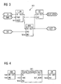
- FIG. 4 A section of the function diagram with the changed structure component is in Fig. 4 shown.
- the new output OUT_NEW is visible at the instance, the original output is no longer visible, although the original function chart is still being processed in the runtime environment at this point in time.
- the replaced structural component In a final step, the replaced structural component must be activated so that the changes and thus also the update of the structural component in the automation system are executed. This is bumpless, ie without interrupting the current operation.
- the changes made are transferred to the automation system in parallel and without retroactive effect on the ongoing operation of the automation system.
- a modified program is created for this purpose in a separate configuration area independent of the current program running in the automation system. This contains the modified block structure as well as the changed parameters or interconnections.
- the program modified by this configuration is switched without interruption and completely transparent to the automation system on the next cycle start. Since the previous program configuration is still available in the programmable controller after switching, there is also the option of switching to the previous configuration either manually or as a result of internal operation (eg program overload).
- the method described can also be realized, for example, in the Java programming language. It is a software tool at the application level.
Landscapes
- Physics & Mathematics (AREA)
- General Physics & Mathematics (AREA)
- Engineering & Computer Science (AREA)
- Automation & Control Theory (AREA)
- Programmable Controllers (AREA)
- Stored Programmes (AREA)
- Supply And Installment Of Electrical Components (AREA)
- Multi-Process Working Machines And Systems (AREA)
- Metal Rolling (AREA)
- Bending Of Plates, Rods, And Pipes (AREA)
- Investigating Or Analyzing Materials By The Use Of Magnetic Means (AREA)
Description
- Die Erfindung betrifft ein Verfahren zum Austausch von Strukturkomponenten für ein Automatisierungssystem.
- Die Automatisierung von Großanlagen, wie beispielsweise Kraftwerksanlagen, erfordert flexible und vielseitig einsetzbare Leittechnik- und Automatisierungssysteme, um die immer komplexer werdenden Steuerungs- und Regelungsaufgaben zu handhaben.
- Veränderungen oder Anpassungen an aktuelle Bedingungen werden im Leittechniksystem mittels der Projektierung durchgeführt. Dabei bedient man sich heute überwiegend graphischer Projektierwerkzeuge. Die im Leittechniksystem in der Projektierungsumgebung durchgeführten Änderungen kommen in der Ablaufumgebung des hierarchisch untergeordneten Automatisierungssystems, welches aus einer Vielzahl speicherprogrammierbarer Steuerungen besteht, zur Ausführung.
- In der europäischen Norm EN 61131-3, auch bekannt als IEC 61131-3 oder IEC 1131-3 werden fünf Programmiersprachen definiert, mit denen speicherprogrammierbare Steuerungen programmiert werden können. Ein Beispiel für ein vollgraphisches Projektierwerkzeug ist die graphische Programmiersprache Continuous Function Chart (CFC), die speziell bei speicherprogrammierbaren Steuerungen in der Automatisierungstechnik Anwendung findet. Bestandteil der oben genannten Norm ist weiterhin die Funktionsbausteinsprache Function Block Diagram (FBS). Es handelt sich dabei ebenfalls um eine grafisch orientierte Programmiersprache. Im FBS-Programm werden Funktionen durch Funktionsbausteine mit Ein- und Ausgängen und deren Verbindungen durch Linien repräsentiert. Weiterhin sind auch Variablen und Konstanten enthalten. Ein solches FBS-Programm wird häufig auch als Funktionsplan bezeichnet.
- Innerhalb eines Funktionsplans existieren unterschiedliche Typen von Funktionsbausteinen. Im Folgenden sollen insbesondere so genannte Strukturkomponenten betrachtet werden, die sich dadurch auszeichnen, dass sie frei gestaltbar und anwenderspezifisch einsetzbar sind. Als Strukturkomponente wird demnach ein Bausteintyp im Sinne der EN 61131-3 bezeichnet, der von einem Anwender durch die Parametrierung und Verschaltung von Basistypen (d.h. Standard-Bausteinen) frei erstellt werden kann. Ein Strukturkomponententyp kann demnach wie ein Standard-Bausteintyp mehrfach projektiert werden.
- Eine Veränderung einer solchen Strukturkomponente war bisher stets mit großem Aufwand bei der Projektierung verbunden. Wie andere Programmbausteine mussten Strukturkomponenten stets manuell an allen Stellen innerhalb des Funktionsplans geändert werden. Insbesondere existierten keine flexiblen Änderungsmöglichkeiten und Aktualisierungsmöglichkeiten von bestehenden bereits projektierten und im Automatisierungssystem aktivierten Strukturkomponenten im laufenden Betrieb. Jegliche Änderungen in der Projektierung waren stets mit erheblichen Einschränkungen des laufenden Betriebs verbunden. Der ablaufende Prozess musste in der Regel unterbrochen werden.
- In der europäischen Patentanmeldung
EP 0 757 305 A1 ist eine freiprogrammierbare Steuerung ("programmable logic controller" = PLC) zur Ausführung eines Steuerprozesses in einem Automatisierungssystem durch die Ausführung eines Anwenderprogramms beschrieben. Innerhalb eines Mikroprozessors der Steuerung kann eine Markierung gesetzt werden, die zur Folge hat, dass während einer bestimmten Zeitdauer keine Änderung an dem Anwenderprogramm durchgeführt werden kann. Eventuell vorzunehmende Änderungen werden in einem Arbeitsspeicher hinterlegt. Soll die Änderung tatsächlich durchgeführt werden, was durch einen entsprechenden Befehl angezeigt wird, muss die zuvor gesetzte Markierung aufgehoben werden. Erst nach Aufhebung der Markierung wird die zuvor im Arbeitsspeicher abgelegte Programmänderung automatisch ausgeführt und der Prozess wird im nächsten Zyklus verändert fortgeführt. - Es ist Aufgabe der Erfindung, ein Verfahren zum Austausch von Strukturkomponenten für ein Automatisierungssystem anzugeben, bei dem der laufende Betrieb des Automatisierungssystems durch Einbringen von projektierten Änderungen nicht unterbrochen wird.
- Diese Aufgabe wird durch die Merkmale des unabhängigen Patentanspruchs 1 gelöst. Vorteilhafte Ausgestaltungen sind jeweils in den abhängigen Patentansprüchen wiedergegeben.
- Erfindungsgemäß wird während des laufenden Betriebs des Automatisierungssystems unabhängig vom Ablauf der Funktion der Strukturkomponente ein Typ einer Strukturkomponente zunächst mittels eines Projektierungswerkzeugs in der Projektierungsumgebung verändert, wobei eine Kennzeichnung des Typs stets erhalten bleibt. Anschließend wird die Instanz der Strukturkomponente im Funktionsplan durch die veränderte Strukturkomponente ausgetauscht und die Strukturänderungen entsprechend vermerkt. In einem nächsten Schritt wird parallel zum und ohne Rückwirkung auf den laufenden Betrieb des Automatisierungssystems die ausgetauschte Strukturkomponente in das Automatisierungssystem übertragen. Im Automatisierungssystem wird dann unterbrechungsfrei auf eine Konfiguration, die die ausgetauschte Strukturkomponente berücksichtigt, umgeschaltet, so dass die veränderte und ausgetauschte Strukturkomponente aktiviert wird.
- Durch die Erfindung ergibt sich vorteilhaft eine flexible und vielseitig einsetzbare technische Lösung zum stoßfreien Ändern von Automatisierungsfunktionen innerhalb eines Leittechniksystems oder Automatisierungssystems.
- Es können anwenderspezifische und frei gestaltbare Strukturkomponenten erstellt und beliebig bei laufendem Betrieb ausgetauscht werden. Eine Aktualisierung von bestehenden, bereits projektierten und im Automatisierungssystem aktivierten Komponenten ist nun ohne Unterbrechungen oder Auswirkungen auf den Prozess durchführbar. Ferner hat der Anwender insbesondere die Möglichkeit, die Aktualisierung des Typs der Strukturkomponente zunächst auf bestimmte Instanzen zu begrenzen. Interne Konsistenzprüfungen gewährleisten ein rückwirkungsfreies Einbringen von Projektierungsänderungen.
- Ein weiterer Vorteil der Erfindung liegt darin, dass es keine zusätzlichen Anforderungen an das zugrundeliegende Automatisierungssystem stellt und somit zielsystem-neutrale Strukturkomponenten erstellt werden können. So kann in einem Leittechniksystem ein und dieselbe Strukturkomponente beispielsweise sowohl in einem Automatisierungssystem SIMATIC S7 der Fa. Siemens als auch in einem Java basierten Automatisierungscontainer zum Ablauf gebracht werden.
- Die Erfindung wird nachfolgend anhand eines in den Zeichnungen dargestellten Ausführungsbeispiels näher erläutert. Dabei zeigen:
- Fig. 1
- ein Schaltbild einer ersten Strukturkomponente SK1,
- Fig. 2
- einen Ausschnitt aus einem Funktionsplan mit einer Instanz des in
Fig. 1 definierten Typs der Struk- turkomponente, - Fig. 3
- ein Schaltbild der veränderten Strukturkomponente SK1,
- Fig. 4
- einen Ausschnitt aus einem Funktionsplan mit einer Instanz des in
Fig. 3 definierten Typs der Struk turkomponente und - Fig. 5
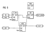
- ein Schaltbild des unterlagerten Funktionsplans der veränderten Strukturkomponente SK1.
-
Figur 1 zeigt ein detailliertes Schaltbild einer Strukturkomponente SK1. Die Strukturkomponente SK1 umfasst in diesem Ausführungsbeispiel drei Standard-Bausteine T_ON, BSEL und AND, die zur Erreichung einer bestimmten Funktion miteinander verschaltet sind. Jeder Baustein besitzt mindestens einen Ein- und einen Ausgang. In diesem Ausführungsbeispiel sind die Eingänge IN und TIME des Bausteins T_ON mit den Konnektoren IN und TIME verbunden. Dementsprechend ist der Eingang IN2 des Bausteins BSEL mit dem Konnektor IN2 verbunden. Die auf der linken Bildseite angeordneten Konnektoren repräsentieren die Eingangsschnittstellen der Strukturkomponente SK1. Durch die Schnittstellen wird die Interaktion mit anderen Programmteilen geregelt. Die Konnektoren der Ausgangsschnittstellen OUT und OUT1 sind auf der rechten Bildseite angeordnet. Sie sind mit den entsprechenden Ausgängen der Bausteine AND und BSEL verbunden. Die Strukturkomponente SK1 mit dem beschriebenen Aufbau wird hier als Strukturkomponente vom Typ A definiert. Bei der Erstellung des Typs der Strukturkomponente SK1 wird intern (d.h. bezogen auf das vorhandene System) eine eindeutige Identifizierung des Typs der Strukturkomponente vergeben. Dazu kann beispielsweise ein GUID (engl. "Globally Unique Identifier") vergeben. Die Erstellung einer solchen Strukturkomponente erfolgt in der Regel manuell mittels eines Projektierungswerkzeugs (z.B. Editor) in einer Projektierungsumgebung (z.B. Leitsystem). Nach der Erstellung des Typs der Strukturkomponente SK1 wird dieser beispielsweise in einer Programmbibliothek hinterlegt. Anschließend kann die Strukturkomponente SK1 wie ein Standard-Baustein in der Projektierung verwendet werden. -
Figur 2 zeigt den Ausschnitt eines Funktionsplans mit einer Instanz des zuvor definierten Typs der Strukturkomponente SK1. Unter Instanz ist die konkrete Verwendung der Strukturkomponente im Funktionsplan zu verstehen. Die Instanzierung der Strukturkomponente bedeutet demnach den Einsatz der Strukturkomponente im Funktionsplan und damit im Gesamtsystem. Die Strukturkomponente vom Typ A wird in dem Funktionsplan projektiert, parametriert und mit anderen Bausteinen verschaltet. Sie ist in diesem Ausführungsbeispiel zwischen den logischen Standard-Bausteinen AND und OR angeordnet. Die Verschaltung mit den anderen Bausteinen kann über die Schnittstellen IN, TIME, IN2 und OUT und OUT1 erfolgen, wobei in diesem Beispiel nur die Schnittstellen IN und OUT1 verschaltet sind. - Um das in eine Strukturkomponente eingeflossene Know-How zu schützen, kann jede Strukturkomponente über ein Password oder eine spezifische Lizenz geschützt werden. Wurde die Strukturkomponente nicht geschützt, so kann der Anwender die detaillierte Verschaltung, wie sie für SK1 beispielsweise in
Fig. 1 dargestellt ist, einsehen. Ohne die erforderliche Autorisierung kann der Anwender die zugrunde liegende Verschaltung nicht einsehen bzw. je nach Zugriffsschutz zwar öffnen aber nicht verändern. - Bei laufendem Betrieb des Automatisierungssystems ist der Funktionsplan mit all seinen Bausteinen aktiviert. Eine Aktivierung der Struktur-Komponente SK 1 bedeutet, dass die Funktion der Strukturkomponente im Automatisierungssystem zum Ablauf gebracht wird. Innerhalb des Funktionsplans kann eine Aktivierung einer Strukturkomponente durch farbliche Kennzeichnung der Ränder der Bausteine, die aktiviert werden, deutlich gemacht werden. Auch im zugehörigen unterlagerten Plan, wie er in
Fig. 1 für die Strukturkomponente SK1 dargestellt ist, kann der Signalfluss anhand einer farblichen Kennzeichnung der einzelnen Bausteine und Konnektoren nachvollzogen werden. - Anschließend wird beschrieben, wie ein Austausch der Strukturkomponente SK1 aus
Fig. 1 bei laufendem Betrieb des Automatisierungssystems unabhängig vom Ablauf der Funktion der Strukturkomponente durchgeführt wird. - Ein Austausch von Strukturkomponenten kann nur für Strukturkomponenten eines Typs durchgeführt werden, d.h. nur für gleiche Kennzeichnungen. Dies bedeutet, dass bei der Veränderung eines Typs der Strukturkomponente die Kennzeichnung der Strukturkomponente, ihre GUID beispielsweise, unverändert bleibt. Versionsnummern werden, wenn nicht explizit durch den Anwender bereits vollzogen, durch das System automatisch erhöht.
- Die eigentliche Änderung der Strukturkomponente oder genauer ausgedrückt des Typs der Strukturkomponente findet offline in der Projektierungsumgebung statt. In der Bibliothek, in der alle Typen von Strukturkomponenten hinterlegt sind, wird in diesem Ausführungsbeispiel die Strukturkomponente SK1 geöffnet, manuell abgeändert und abgespeichert. Änderungen des Typs der Strukturkomponente können durch Hinzufügen oder Entfernen von enthaltenen Bausteinen, von Verschaltungen, von Parametern oder von externen Schnittstellen erfolgen.
- Der veränderte Typ der Strukturkomponente Typ A des beschriebenen Ausführungsbeispiels ist im Schaltbild von
Fig. 3 dargestellt. Der Baustein AND von SK1 mit seiner zugehörigen Ausgangsschnittstelle OUT wurde entfernt und durch einen Baustein OR ersetzt. Die Verschaltungen innerhalb der Strukturkomponente wurden entsprechend modifiziert. Das gleiche gilt für die Ausgangsschnittstelle OUT, die jetzt zu OUT_NEW abgeändert wurde. - In einem nächsten Schritt wird in der Projektierungsumgebung die Aktualisierung der bereits in der Bibliothek platzierten veränderten Strukturkomponente des betreffenden Typs, welche durch die entsprechende Kennzeichnung identifiziert ist, angestoßen. Für die Aktualisierung können alle Instanzen oder nur eine Teilmenge ausgewählt werden. Dies bedeutet, dass die Änderungen der Strukturkomponente SK1 an allen Stellen des Funktionsplans durchgeführt werden. Die Ausführung der Funktion der ursprünglichen Strukturkomponente in der Ablaufumgebung des Automatisierungssystems wird dabei nicht gestört, da die Änderungen bisher nur in der Projektierungsumgebung vorgenommen wurden.
- Ein Ausschnitt des Funktionsplans mit der veränderten Strukturkomponente ist in
Fig. 4 dargestellt. An der Instanz ist der neue Ausgang OUT_NEW sichtbar, der ursprünglich vorhandene Ausgang ist nicht mehr sichtbar, obwohl der ursprüngliche Funktionsplan zu diesem Zeitpunkt in der Ablaufumgebung noch abgearbeitet wird. - Im zugehörigen unterlagerten Plan, wie er in
Fig. 5 dargestellt ist, sind die vorgenommenen Änderungen im Detail nachvollziehbar. Der ursprünglich vorhandene Baustein AND ist immer noch sichtbar, jedoch farblich abgesetzt und somit graphisch markiert. Dies bedeutet, dass der Baustein in der Automatisierung aktuell zum Ablauf kommt und noch aktiviert ist. Durch die graphische Markierung ist der Baustein jedoch in diesem Ausführungsbeispiel bereits als gelöscht gekennzeichnet, d.h. es ist kenntlich gemacht, dass der Baustein im Zuge der nächsten Aktivierung gelöscht werden soll. Die Strukturänderung ist demnach auf diese Weise vermerkt worden. Der neu hinzugefügte Baustein OR ist graphisch derart dargestellt, dass erkennbar ist, dass er noch nicht aktiviert worden ist. Beispielsweise kann der Rand des Bausteins OR farblich anders markiert werden als der Rand der aktivierten Bausteine. - Durch den Austausch der Instanz der Strukturkomponente im Funktionsplan sind intern demnach die zuvor am Typ der Strukturkomponente durchgeführten Änderungen in allen projektierten Instanzen in der Projektierungsumgebung nachvollzogen worden, als ob der Anwender praktisch gleichzeitig für alle betroffenen Instanzen die Änderungen manuell durchgeführt hätte.
- In einem letzten Schritt muss die ausgetauschte Strukturkomponente aktiviert werden, damit die Änderungen und damit auch die Aktualisierung der Strukturkomponente im Automatisierungssystem zur Ausführung kommen. Dies erfolgt stoßfrei, d.h. ohne Unterbrechung des laufenden Betriebs. Dazu werden parallel und ohne Rückwirkung auf den laufenden Betrieb des Automatisierungssystems die vorgenommenen Änderungen in das Automatisierungssystem übertragen. Innerhalb des Automatisierungssystems wird hierzu in einem separaten, vom aktuellen im Automatisierungssystem ablaufenden Programm unabhängigen Konfigurationsbereich ein verändertes Programm angelegt. Dieses enthält die durch die geänderte Strukturkomponente geänderte Bausteinstruktur sowie die veränderten Parameter bzw. Verschaltungen. Nachdem diese Parallelkonfiguration vollständig durchgeführt worden ist, wird auf das durch diese Konfiguration veränderte Programm unterbrechungsfrei und für das Automatisierungssystem vollkommen transparent beim nächsten Zyklusstart umgeschaltet. Da nach der Umschaltung die vorherige Programmkonfiguration noch im Automatisierungsgerät vorhanden ist, besteht darüber hinaus die Möglichkeit, manuell oder aufgrund einer internen Bedienung (z.B. bei Programm-Überlast) auf die vorherige Konfiguration umzuschalten.
- Nach der Aktivierung zeigt sich der in den
Figuren 3 und 4 gezeigte Funktionsplan, wobei nun der OR-Baustein aktiviert ist, was ebenfalls graphisch angezeigt ist. - Das beschriebene Verfahren kann beispielsweise auch in der Programmiersprache Java realisiert werden. Es handelt sich um ein Software-Werkzeug auf Applikationsebene.
Claims (5)
- Verfahren zum Austausch von Strukturkomponenten für ein Automatisierungssystem
wobei- ein Typ einer Strukturkomponente mittels eines Projektierungswerkzeugs in einer Projektierungsumgebung erstellt und eindeutig gekennzeichnet wird,- die Strukturkomponente in einem Funktionsplan projektiert, parametriert und mit anderen Bausteinen verschaltet wird,- die projektierte Instanz der Strukturkomponente in der Ablaufumgebung aktiviert wird, wodurch die Funktion im Automatisierungssystem zum Ablauf gebracht wird,dadurch gekennzeichnet,
dass während des laufenden Betriebs des Automatisierungssystems unabhängig vom Ablauf der Funktion der Strukturkomponente- der Typ der Strukturkomponente mittels des Projektierungswerkzeugs in der Projektierungsumgebung geöffnet und verändert wird, wobei die Kennzeichnung erhalten bleibt,- die Instanz der Strukturkomponente im Funktionsplan durch die veränderte Strukturkomponente ausgetauscht wird, wobei die Strukturänderungen entsprechend vermerkt werden,- parallel und ohne Rückwirkung auf den laufenden Betrieb des Automatisierungssystems die ausgetauschte Strukturkomponente in das Automatisierungssystem übertragen wird,- im Automatisierungssystem unterbrechungsfrei auf die durchgeführte Änderung umgeschaltet wird, so dass die veränderte und ausgetauschte Strukturkomponente aktiviert wird. - Verfahren nach Anspruch 1,
dadurch gekennzeichnet,
dass die Änderung des Typs der Strukturkomponente durch Hinzufügen oder Entfernen von enthaltenen Bausteinen, von Verschaltungen, von Parametern oder von externen Schnittstellen erfolgt. - Verfahren nach Anspruch 1 oder 2,
dadurch gekennzeichnet,
dass innerhalb des Automatisierungssystems mindestens zwei Konfigurationen der Projektierung angelegt sind,
dass im laufenden Betrieb stets eine dieser Konfigurationen im Automatisierungssystem abläuft
dass die ausgetauschte Strukturkomponente bei laufender erster Konfiguration in die zweite Konfiguration übertragen wird, und
dass anschließend unterbrechungsfrei auf die zweite Konfiguration umgeschaltet wird, so dass die veränderte und ausgetauschte Strukturkomponente aktiviert wird. - Verfahren nach Anspruch 3,
dadurch gekennzeichnet,
dass im Automatisierungssystem unterbrechungsfrei, falls erforderlich, auf die vorherige Konfiguration umgeschaltet werden kann. - Verfahren nach einem der vorhergehenden Ansprüche,
dadurch gekennzeichnet,
dass vor dem Einbringen projektierter Änderungen Konsistenzprüfungen im Automatisierungssystem durchgeführt werden.
Applications Claiming Priority (2)
| Application Number | Priority Date | Filing Date | Title |
|---|---|---|---|
| DE102007007350 | 2007-02-14 | ||
| PCT/EP2008/051800 WO2008098989A1 (de) | 2007-02-14 | 2008-02-14 | Verfahren zum austausch von strukturkomponenten für ein automatisierungssystem |
Publications (2)
| Publication Number | Publication Date |
|---|---|
| EP2126643A1 EP2126643A1 (de) | 2009-12-02 |
| EP2126643B1 true EP2126643B1 (de) | 2010-10-20 |
Family
ID=39524239
Family Applications (1)
| Application Number | Title | Priority Date | Filing Date |
|---|---|---|---|
| EP08708994A Not-in-force EP2126643B1 (de) | 2007-02-14 | 2008-02-14 | Verfahren zum austausch von strukturkomponenten für ein automatisierungssystem |
Country Status (11)
| Country | Link |
|---|---|
| US (1) | US20100094438A1 (de) |
| EP (1) | EP2126643B1 (de) |
| JP (1) | JP2010519615A (de) |
| CN (1) | CN101611358B (de) |
| AT (1) | ATE485544T1 (de) |
| AU (1) | AU2008214626B2 (de) |
| DE (1) | DE502008001589D1 (de) |
| ES (1) | ES2354504T3 (de) |
| MX (1) | MX2009008743A (de) |
| RU (1) | RU2449339C2 (de) |
| WO (1) | WO2008098989A1 (de) |
Families Citing this family (3)
| Publication number | Priority date | Publication date | Assignee | Title |
|---|---|---|---|---|
| US10185308B2 (en) * | 2012-04-30 | 2019-01-22 | Fisher Controls International Llc | Methods and systems to provide update information of a device description of a field instrument |
| DE102015106116A1 (de) * | 2015-04-21 | 2016-10-27 | Phoenix Contact Gmbh & Co. Kg | Verfahren und Steuereinrichtung zur flexiblen Prozesssteuerung |
| EP3088976B1 (de) * | 2015-04-28 | 2017-11-29 | Siemens Aktiengesellschaft | Verfahren zum betreiben einer automatisierungseinrichtung und automatisierungseinrichtung |
Family Cites Families (9)
| Publication number | Priority date | Publication date | Assignee | Title |
|---|---|---|---|---|
| JP3371349B2 (ja) * | 1995-07-21 | 2003-01-27 | オムロン株式会社 | 制御処理装置 |
| US5909368A (en) * | 1996-04-12 | 1999-06-01 | Fisher-Rosemount Systems, Inc. | Process control system using a process control strategy distributed among multiple control elements |
| US20040090439A1 (en) * | 2002-11-07 | 2004-05-13 | Holger Dillner | Recognition and interpretation of graphical and diagrammatic representations |
| US7587710B2 (en) * | 2003-02-14 | 2009-09-08 | Siemens Aktiengesellschaft | Method for determining the processing sequence of function blocks of an automated system and corresponding automated system |
| DE102004061063A1 (de) * | 2004-12-18 | 2006-06-29 | Bosch Rexroth Aktiengesellschaft | Verfahren zur dynamischen Konfiguration einer Bedienoberfläche eines Funktionsbausteins |
| US7275196B2 (en) * | 2005-11-23 | 2007-09-25 | M2000 S.A. | Runtime reconfiguration of reconfigurable circuits |
| US7561930B2 (en) * | 2006-10-02 | 2009-07-14 | Fisher-Rosemount Systems, Inc. | Dynamic modifier function blocks for use in a process control system |
| US8216067B2 (en) * | 2008-11-14 | 2012-07-10 | Aruze Gaming America, Inc. | Detection device capable of accurately reading dots on dice |
| US8615236B2 (en) * | 2010-06-04 | 2013-12-24 | Palm, Inc. | System and method for dynamically managing connections using feature prioritization |
-
2008
- 2008-02-14 DE DE502008001589T patent/DE502008001589D1/de active Active
- 2008-02-14 CN CN2008800051523A patent/CN101611358B/zh not_active Expired - Fee Related
- 2008-02-14 EP EP08708994A patent/EP2126643B1/de not_active Not-in-force
- 2008-02-14 MX MX2009008743A patent/MX2009008743A/es active IP Right Grant
- 2008-02-14 US US12/526,846 patent/US20100094438A1/en not_active Abandoned
- 2008-02-14 RU RU2009134127/08A patent/RU2449339C2/ru not_active IP Right Cessation
- 2008-02-14 WO PCT/EP2008/051800 patent/WO2008098989A1/de not_active Ceased
- 2008-02-14 JP JP2009549831A patent/JP2010519615A/ja not_active Abandoned
- 2008-02-14 ES ES08708994T patent/ES2354504T3/es active Active
- 2008-02-14 AT AT08708994T patent/ATE485544T1/de active
- 2008-02-14 AU AU2008214626A patent/AU2008214626B2/en not_active Ceased
Also Published As
| Publication number | Publication date |
|---|---|
| US20100094438A1 (en) | 2010-04-15 |
| EP2126643A1 (de) | 2009-12-02 |
| RU2449339C2 (ru) | 2012-04-27 |
| MX2009008743A (es) | 2009-08-27 |
| CN101611358B (zh) | 2011-10-05 |
| AU2008214626B2 (en) | 2011-05-12 |
| RU2009134127A (ru) | 2011-03-20 |
| JP2010519615A (ja) | 2010-06-03 |
| AU2008214626A1 (en) | 2008-08-21 |
| WO2008098989A1 (de) | 2008-08-21 |
| ATE485544T1 (de) | 2010-11-15 |
| CN101611358A (zh) | 2009-12-23 |
| ES2354504T3 (es) | 2011-03-15 |
| DE502008001589D1 (de) | 2010-12-02 |
Similar Documents
| Publication | Publication Date | Title |
|---|---|---|
| DE102009047025B3 (de) | Echtzeit-Laufzeitsystem und Funktionsmodul für ein solches Laufzeitsystem | |
| WO2010060575A1 (de) | Verfahren und vorrichtung zum erstellen eines anwenderprogramms für eine sicherheitssteuerung | |
| EP1224512B1 (de) | Steuerungssystem einer numerischen werkzeugmaschine mit einer wiederverwendbaren softwarestruktur | |
| DE102009019088A1 (de) | Sicherheitssteuerung zum Steuern einer automatisierten Anlage und Verfahren zum Erstellen eines Anwenderprogramms für eine Sicherheitssteuerung | |
| EP0553621A1 (de) | Programmierbare Computersteuerung für eine Werkzeugmaschine | |
| EP2126643B1 (de) | Verfahren zum austausch von strukturkomponenten für ein automatisierungssystem | |
| EP2422248B1 (de) | System und verfahren zum verteilen von projektdaten einer sicherheitssteuerung einer automatisierten anlage auf die steuerungskomponenten | |
| EP3320431A1 (de) | Computerimplementiertes verfahren zur bearbeitung von datenobjektvarianten | |
| EP1634130A1 (de) | Vorrichtung und verfahren zur programmierung und/oder ausführung von programmen für industrielle automatisierungssysteme | |
| DE19630415A1 (de) | Software-Werkzeug | |
| EP1950635B1 (de) | Verfahren zum Betrieb eines Automatisierungssystems | |
| EP4123396B1 (de) | Technik zur realisierung einer visualisierung für eine automatisierungstechnische anlage mit einer speicherprogrammierbaren steuerung | |
| DE102008023873A1 (de) | Verfahren zum Betrieb eines Antriebssystems | |
| DE10128158A1 (de) | Programmierwerkzeug und Programmierverfahren | |
| EP4453674A1 (de) | Technik zur parametrierung und/oder konfiguration für eine auf einer speicher-programmierbaren steuerung basierenden vorrichtung | |
| DE3545957A1 (de) | Verfahren und schaltungsanordnung zur automatischen abarbeitung von einrichtefunktionen in numerischen steuerungen | |
| EP1185910B1 (de) | Verfahren zum synchronisierten hochlauf einer numerischen steuerung | |
| EP1226473A2 (de) | Zustandssteuerung von technischen systemen | |
| EP1644881B1 (de) | Verfahren zum projektieren und/oder konfigurieren eines projektes | |
| EP1184760B1 (de) | Verfahren zur Steuerung und/oder Regelung eines technischen Prozesses | |
| DE102005008136A1 (de) | Entwicklungssystem für Prozessleitsysteme sowie zugehöriges Verfahren und Computerprogrammprodukt | |
| EP2093663A1 (de) | Engineering-System für die Entwicklung eines Projektes und Verfahren | |
| DE10233211A1 (de) | Computersystem zur Konfiguration von Firmware für ein Automatisierungsgerät | |
| DE102019006533A1 (de) | Numerische Steuervorrichtung | |
| DD233001A1 (de) | Schaltungsanordnung zur automatischen abarbeitung von einrichtefunktionen |
Legal Events
| Date | Code | Title | Description |
|---|---|---|---|
| PUAI | Public reference made under article 153(3) epc to a published international application that has entered the european phase |
Free format text: ORIGINAL CODE: 0009012 |
|
| 17P | Request for examination filed |
Effective date: 20090731 |
|
| AK | Designated contracting states |
Kind code of ref document: A1 Designated state(s): AT BE BG CH CY CZ DE DK EE ES FI FR GB GR HR HU IE IS IT LI LT LU LV MC MT NL NO PL PT RO SE SI SK TR |
|
| 17Q | First examination report despatched |
Effective date: 20091207 |
|
| GRAP | Despatch of communication of intention to grant a patent |
Free format text: ORIGINAL CODE: EPIDOSNIGR1 |
|
| DAX | Request for extension of the european patent (deleted) | ||
| GRAS | Grant fee paid |
Free format text: ORIGINAL CODE: EPIDOSNIGR3 |
|
| GRAA | (expected) grant |
Free format text: ORIGINAL CODE: 0009210 |
|
| AK | Designated contracting states |
Kind code of ref document: B1 Designated state(s): AT BE BG CH CY CZ DE DK EE ES FI FR GB GR HR HU IE IS IT LI LT LU LV MC MT NL NO PL PT RO SE SI SK TR |
|
| REG | Reference to a national code |
Ref country code: GB Ref legal event code: FG4D Free format text: NOT ENGLISH |
|
| REG | Reference to a national code |
Ref country code: CH Ref legal event code: EP |
|
| REG | Reference to a national code |
Ref country code: IE Ref legal event code: FG4D Free format text: LANGUAGE OF EP DOCUMENT: GERMAN |
|
| REF | Corresponds to: |
Ref document number: 502008001589 Country of ref document: DE Date of ref document: 20101202 Kind code of ref document: P |
|
| REG | Reference to a national code |
Ref country code: NL Ref legal event code: T3 |
|
| REG | Reference to a national code |
Ref country code: ES Ref legal event code: FG2A Effective date: 20110303 |
|
| LTIE | Lt: invalidation of european patent or patent extension |
Effective date: 20101020 |
|
| PG25 | Lapsed in a contracting state [announced via postgrant information from national office to epo] |
Ref country code: LT Free format text: LAPSE BECAUSE OF FAILURE TO SUBMIT A TRANSLATION OF THE DESCRIPTION OR TO PAY THE FEE WITHIN THE PRESCRIBED TIME-LIMIT Effective date: 20101020 Ref country code: NO Free format text: LAPSE BECAUSE OF FAILURE TO SUBMIT A TRANSLATION OF THE DESCRIPTION OR TO PAY THE FEE WITHIN THE PRESCRIBED TIME-LIMIT Effective date: 20110120 |
|
| REG | Reference to a national code |
Ref country code: IE Ref legal event code: FD4D |
|
| PG25 | Lapsed in a contracting state [announced via postgrant information from national office to epo] |
Ref country code: SE Free format text: LAPSE BECAUSE OF FAILURE TO SUBMIT A TRANSLATION OF THE DESCRIPTION OR TO PAY THE FEE WITHIN THE PRESCRIBED TIME-LIMIT Effective date: 20101020 Ref country code: SI Free format text: LAPSE BECAUSE OF FAILURE TO SUBMIT A TRANSLATION OF THE DESCRIPTION OR TO PAY THE FEE WITHIN THE PRESCRIBED TIME-LIMIT Effective date: 20101020 Ref country code: LV Free format text: LAPSE BECAUSE OF FAILURE TO SUBMIT A TRANSLATION OF THE DESCRIPTION OR TO PAY THE FEE WITHIN THE PRESCRIBED TIME-LIMIT Effective date: 20101020 Ref country code: PT Free format text: LAPSE BECAUSE OF FAILURE TO SUBMIT A TRANSLATION OF THE DESCRIPTION OR TO PAY THE FEE WITHIN THE PRESCRIBED TIME-LIMIT Effective date: 20110221 Ref country code: FI Free format text: LAPSE BECAUSE OF FAILURE TO SUBMIT A TRANSLATION OF THE DESCRIPTION OR TO PAY THE FEE WITHIN THE PRESCRIBED TIME-LIMIT Effective date: 20101020 Ref country code: HR Free format text: LAPSE BECAUSE OF FAILURE TO SUBMIT A TRANSLATION OF THE DESCRIPTION OR TO PAY THE FEE WITHIN THE PRESCRIBED TIME-LIMIT Effective date: 20101020 Ref country code: IS Free format text: LAPSE BECAUSE OF FAILURE TO SUBMIT A TRANSLATION OF THE DESCRIPTION OR TO PAY THE FEE WITHIN THE PRESCRIBED TIME-LIMIT Effective date: 20110220 Ref country code: BG Free format text: LAPSE BECAUSE OF FAILURE TO SUBMIT A TRANSLATION OF THE DESCRIPTION OR TO PAY THE FEE WITHIN THE PRESCRIBED TIME-LIMIT Effective date: 20110120 |
|
| PG25 | Lapsed in a contracting state [announced via postgrant information from national office to epo] |
Ref country code: GR Free format text: LAPSE BECAUSE OF FAILURE TO SUBMIT A TRANSLATION OF THE DESCRIPTION OR TO PAY THE FEE WITHIN THE PRESCRIBED TIME-LIMIT Effective date: 20110121 |
|
| PG25 | Lapsed in a contracting state [announced via postgrant information from national office to epo] |
Ref country code: IE Free format text: LAPSE BECAUSE OF FAILURE TO SUBMIT A TRANSLATION OF THE DESCRIPTION OR TO PAY THE FEE WITHIN THE PRESCRIBED TIME-LIMIT Effective date: 20101020 Ref country code: EE Free format text: LAPSE BECAUSE OF FAILURE TO SUBMIT A TRANSLATION OF THE DESCRIPTION OR TO PAY THE FEE WITHIN THE PRESCRIBED TIME-LIMIT Effective date: 20101020 |
|
| PLBE | No opposition filed within time limit |
Free format text: ORIGINAL CODE: 0009261 |
|
| STAA | Information on the status of an ep patent application or granted ep patent |
Free format text: STATUS: NO OPPOSITION FILED WITHIN TIME LIMIT |
|
| BERE | Be: lapsed |
Owner name: SIEMENS A.G. Effective date: 20110228 |
|
| PG25 | Lapsed in a contracting state [announced via postgrant information from national office to epo] |
Ref country code: SK Free format text: LAPSE BECAUSE OF FAILURE TO SUBMIT A TRANSLATION OF THE DESCRIPTION OR TO PAY THE FEE WITHIN THE PRESCRIBED TIME-LIMIT Effective date: 20101020 Ref country code: DK Free format text: LAPSE BECAUSE OF FAILURE TO SUBMIT A TRANSLATION OF THE DESCRIPTION OR TO PAY THE FEE WITHIN THE PRESCRIBED TIME-LIMIT Effective date: 20101020 Ref country code: PL Free format text: LAPSE BECAUSE OF FAILURE TO SUBMIT A TRANSLATION OF THE DESCRIPTION OR TO PAY THE FEE WITHIN THE PRESCRIBED TIME-LIMIT Effective date: 20101020 Ref country code: RO Free format text: LAPSE BECAUSE OF FAILURE TO SUBMIT A TRANSLATION OF THE DESCRIPTION OR TO PAY THE FEE WITHIN THE PRESCRIBED TIME-LIMIT Effective date: 20101020 |
|
| 26N | No opposition filed |
Effective date: 20110721 |
|
| PG25 | Lapsed in a contracting state [announced via postgrant information from national office to epo] |
Ref country code: MC Free format text: LAPSE BECAUSE OF NON-PAYMENT OF DUE FEES Effective date: 20110228 |
|
| REG | Reference to a national code |
Ref country code: DE Ref legal event code: R097 Ref document number: 502008001589 Country of ref document: DE Effective date: 20110721 |
|
| PG25 | Lapsed in a contracting state [announced via postgrant information from national office to epo] |
Ref country code: BE Free format text: LAPSE BECAUSE OF NON-PAYMENT OF DUE FEES Effective date: 20110228 |
|
| PG25 | Lapsed in a contracting state [announced via postgrant information from national office to epo] |
Ref country code: MT Free format text: LAPSE BECAUSE OF FAILURE TO SUBMIT A TRANSLATION OF THE DESCRIPTION OR TO PAY THE FEE WITHIN THE PRESCRIBED TIME-LIMIT Effective date: 20101020 |
|
| REG | Reference to a national code |
Ref country code: CH Ref legal event code: PL |
|
| PG25 | Lapsed in a contracting state [announced via postgrant information from national office to epo] |
Ref country code: LI Free format text: LAPSE BECAUSE OF NON-PAYMENT OF DUE FEES Effective date: 20120229 Ref country code: CH Free format text: LAPSE BECAUSE OF NON-PAYMENT OF DUE FEES Effective date: 20120229 |
|
| PG25 | Lapsed in a contracting state [announced via postgrant information from national office to epo] |
Ref country code: CY Free format text: LAPSE BECAUSE OF FAILURE TO SUBMIT A TRANSLATION OF THE DESCRIPTION OR TO PAY THE FEE WITHIN THE PRESCRIBED TIME-LIMIT Effective date: 20101020 Ref country code: LU Free format text: LAPSE BECAUSE OF NON-PAYMENT OF DUE FEES Effective date: 20110214 |
|
| PG25 | Lapsed in a contracting state [announced via postgrant information from national office to epo] |
Ref country code: HU Free format text: LAPSE BECAUSE OF FAILURE TO SUBMIT A TRANSLATION OF THE DESCRIPTION OR TO PAY THE FEE WITHIN THE PRESCRIBED TIME-LIMIT Effective date: 20101020 |
|
| REG | Reference to a national code |
Ref country code: AT Ref legal event code: MM01 Ref document number: 485544 Country of ref document: AT Kind code of ref document: T Effective date: 20130214 |
|
| PG25 | Lapsed in a contracting state [announced via postgrant information from national office to epo] |
Ref country code: AT Free format text: LAPSE BECAUSE OF NON-PAYMENT OF DUE FEES Effective date: 20130214 |
|
| REG | Reference to a national code |
Ref country code: FR Ref legal event code: PLFP Year of fee payment: 8 |
|
| PGFP | Annual fee paid to national office [announced via postgrant information from national office to epo] |
Ref country code: NL Payment date: 20150202 Year of fee payment: 8 |
|
| PGFP | Annual fee paid to national office [announced via postgrant information from national office to epo] |
Ref country code: ES Payment date: 20150327 Year of fee payment: 8 Ref country code: CZ Payment date: 20150209 Year of fee payment: 8 Ref country code: IT Payment date: 20150228 Year of fee payment: 8 |
|
| PGFP | Annual fee paid to national office [announced via postgrant information from national office to epo] |
Ref country code: FR Payment date: 20150212 Year of fee payment: 8 Ref country code: GB Payment date: 20150211 Year of fee payment: 8 Ref country code: TR Payment date: 20150130 Year of fee payment: 8 |
|
| PGFP | Annual fee paid to national office [announced via postgrant information from national office to epo] |
Ref country code: DE Payment date: 20150420 Year of fee payment: 8 |
|
| REG | Reference to a national code |
Ref country code: DE Ref legal event code: R119 Ref document number: 502008001589 Country of ref document: DE |
|
| GBPC | Gb: european patent ceased through non-payment of renewal fee |
Effective date: 20160214 |
|
| REG | Reference to a national code |
Ref country code: NL Ref legal event code: MM Effective date: 20160301 |
|
| REG | Reference to a national code |
Ref country code: FR Ref legal event code: ST Effective date: 20161028 |
|
| PG25 | Lapsed in a contracting state [announced via postgrant information from national office to epo] |
Ref country code: CZ Free format text: LAPSE BECAUSE OF NON-PAYMENT OF DUE FEES Effective date: 20160214 |
|
| PG25 | Lapsed in a contracting state [announced via postgrant information from national office to epo] |
Ref country code: IT Free format text: LAPSE BECAUSE OF NON-PAYMENT OF DUE FEES Effective date: 20160214 |
|
| PG25 | Lapsed in a contracting state [announced via postgrant information from national office to epo] |
Ref country code: NL Free format text: LAPSE BECAUSE OF NON-PAYMENT OF DUE FEES Effective date: 20160301 Ref country code: DE Free format text: LAPSE BECAUSE OF NON-PAYMENT OF DUE FEES Effective date: 20160901 Ref country code: GB Free format text: LAPSE BECAUSE OF NON-PAYMENT OF DUE FEES Effective date: 20160214 Ref country code: FR Free format text: LAPSE BECAUSE OF NON-PAYMENT OF DUE FEES Effective date: 20160229 |
|
| PG25 | Lapsed in a contracting state [announced via postgrant information from national office to epo] |
Ref country code: ES Free format text: LAPSE BECAUSE OF NON-PAYMENT OF DUE FEES Effective date: 20160215 |
|
| REG | Reference to a national code |
Ref country code: ES Ref legal event code: FD2A Effective date: 20181207 |
|
| PG25 | Lapsed in a contracting state [announced via postgrant information from national office to epo] |
Ref country code: TR Free format text: LAPSE BECAUSE OF NON-PAYMENT OF DUE FEES Effective date: 20160214 |