EP2126559B1 - Verfahren und vorrichtung zur inspektion eines werkstücks mit winkelversetzten ultraschallsignalen - Google Patents
Verfahren und vorrichtung zur inspektion eines werkstücks mit winkelversetzten ultraschallsignalen Download PDFInfo
- Publication number
- EP2126559B1 EP2126559B1 EP08732312.7A EP08732312A EP2126559B1 EP 2126559 B1 EP2126559 B1 EP 2126559B1 EP 08732312 A EP08732312 A EP 08732312A EP 2126559 B1 EP2126559 B1 EP 2126559B1
- Authority
- EP
- European Patent Office
- Prior art keywords
- ultrasonic
- workpiece
- signals
- predefined
- backscattered
- Prior art date
- Legal status (The legal status is an assumption and is not a legal conclusion. Google has not performed a legal analysis and makes no representation as to the accuracy of the status listed.)
- Not-in-force
Links
- 238000000034 method Methods 0.000 title claims description 26
- 238000007689 inspection Methods 0.000 claims description 74
- 238000012545 processing Methods 0.000 claims description 16
- 230000001186 cumulative effect Effects 0.000 claims description 9
- 230000002547 anomalous effect Effects 0.000 claims description 6
- 230000004044 response Effects 0.000 claims description 6
- 230000001154 acute effect Effects 0.000 claims description 3
- 230000003685 thermal hair damage Effects 0.000 description 44
- 239000002131 composite material Substances 0.000 description 18
- 230000007547 defect Effects 0.000 description 16
- 238000004519 manufacturing process Methods 0.000 description 10
- 239000000463 material Substances 0.000 description 9
- 238000012360 testing method Methods 0.000 description 8
- 230000006378 damage Effects 0.000 description 7
- 239000011148 porous material Substances 0.000 description 7
- 230000032798 delamination Effects 0.000 description 5
- 230000000694 effects Effects 0.000 description 5
- 238000007654 immersion Methods 0.000 description 5
- 238000001514 detection method Methods 0.000 description 4
- 239000000523 sample Substances 0.000 description 4
- XLYOFNOQVPJJNP-UHFFFAOYSA-N water Substances O XLYOFNOQVPJJNP-UHFFFAOYSA-N 0.000 description 4
- 230000001066 destructive effect Effects 0.000 description 3
- 230000033001 locomotion Effects 0.000 description 3
- 239000011159 matrix material Substances 0.000 description 3
- 229910052751 metal Inorganic materials 0.000 description 3
- 239000002184 metal Substances 0.000 description 3
- 239000007787 solid Substances 0.000 description 3
- 238000004566 IR spectroscopy Methods 0.000 description 2
- 230000015556 catabolic process Effects 0.000 description 2
- 230000008859 change Effects 0.000 description 2
- 238000000576 coating method Methods 0.000 description 2
- 238000006731 degradation reaction Methods 0.000 description 2
- 230000005294 ferromagnetic effect Effects 0.000 description 2
- 239000000835 fiber Substances 0.000 description 2
- 239000006260 foam Substances 0.000 description 2
- 150000002739 metals Chemical class 0.000 description 2
- 238000012986 modification Methods 0.000 description 2
- 230000004048 modification Effects 0.000 description 2
- 239000003973 paint Substances 0.000 description 2
- 239000004033 plastic Substances 0.000 description 2
- 229920003023 plastic Polymers 0.000 description 2
- 230000008569 process Effects 0.000 description 2
- 239000010936 titanium Substances 0.000 description 2
- 238000002604 ultrasonography Methods 0.000 description 2
- 229910000838 Al alloy Inorganic materials 0.000 description 1
- OKTJSMMVPCPJKN-UHFFFAOYSA-N Carbon Chemical compound [C] OKTJSMMVPCPJKN-UHFFFAOYSA-N 0.000 description 1
- 229920000049 Carbon (fiber) Polymers 0.000 description 1
- 239000004593 Epoxy Substances 0.000 description 1
- 229910001069 Ti alloy Inorganic materials 0.000 description 1
- RTAQQCXQSZGOHL-UHFFFAOYSA-N Titanium Chemical compound [Ti] RTAQQCXQSZGOHL-UHFFFAOYSA-N 0.000 description 1
- NIXOWILDQLNWCW-UHFFFAOYSA-N acrylic acid group Chemical group C(C=C)(=O)O NIXOWILDQLNWCW-UHFFFAOYSA-N 0.000 description 1
- 229910052782 aluminium Inorganic materials 0.000 description 1
- XAGFODPZIPBFFR-UHFFFAOYSA-N aluminium Chemical compound [Al] XAGFODPZIPBFFR-UHFFFAOYSA-N 0.000 description 1
- -1 aluminum alloy Chemical class 0.000 description 1
- 238000004458 analytical method Methods 0.000 description 1
- 230000003466 anti-cipated effect Effects 0.000 description 1
- 230000008901 benefit Effects 0.000 description 1
- 230000005540 biological transmission Effects 0.000 description 1
- 239000004917 carbon fiber Substances 0.000 description 1
- 239000000919 ceramic Substances 0.000 description 1
- 238000006243 chemical reaction Methods 0.000 description 1
- 239000011248 coating agent Substances 0.000 description 1
- 238000007796 conventional method Methods 0.000 description 1
- 230000008878 coupling Effects 0.000 description 1
- 238000010168 coupling process Methods 0.000 description 1
- 238000005859 coupling reaction Methods 0.000 description 1
- 238000005336 cracking Methods 0.000 description 1
- 230000003247 decreasing effect Effects 0.000 description 1
- 230000007812 deficiency Effects 0.000 description 1
- 238000010586 diagram Methods 0.000 description 1
- 238000011156 evaluation Methods 0.000 description 1
- 239000012530 fluid Substances 0.000 description 1
- HZHFFEYYPYZMNU-UHFFFAOYSA-K gadodiamide Chemical compound [Gd+3].CNC(=O)CN(CC([O-])=O)CCN(CC([O-])=O)CCN(CC([O-])=O)CC(=O)NC HZHFFEYYPYZMNU-UHFFFAOYSA-K 0.000 description 1
- 230000004313 glare Effects 0.000 description 1
- 229910002804 graphite Inorganic materials 0.000 description 1
- 239000010439 graphite Substances 0.000 description 1
- 230000003993 interaction Effects 0.000 description 1
- 230000002452 interceptive effect Effects 0.000 description 1
- 238000012804 iterative process Methods 0.000 description 1
- 239000007788 liquid Substances 0.000 description 1
- 239000000314 lubricant Substances 0.000 description 1
- 238000005259 measurement Methods 0.000 description 1
- VNWKTOKETHGBQD-UHFFFAOYSA-N methane Chemical compound C VNWKTOKETHGBQD-UHFFFAOYSA-N 0.000 description 1
- 238000012544 monitoring process Methods 0.000 description 1
- 230000003287 optical effect Effects 0.000 description 1
- 238000013021 overheating Methods 0.000 description 1
- 229920000642 polymer Polymers 0.000 description 1
- 230000008439 repair process Effects 0.000 description 1
- 239000011347 resin Substances 0.000 description 1
- 229920005989 resin Polymers 0.000 description 1
- 239000003351 stiffener Substances 0.000 description 1
- 238000005382 thermal cycling Methods 0.000 description 1
- 229910052719 titanium Inorganic materials 0.000 description 1
- 239000011800 void material Substances 0.000 description 1
Images


Classifications
-
- G—PHYSICS
- G01—MEASURING; TESTING
- G01N—INVESTIGATING OR ANALYSING MATERIALS BY DETERMINING THEIR CHEMICAL OR PHYSICAL PROPERTIES
- G01N29/00—Investigating or analysing materials by the use of ultrasonic, sonic or infrasonic waves; Visualisation of the interior of objects by transmitting ultrasonic or sonic waves through the object
- G01N29/04—Analysing solids
- G01N29/11—Analysing solids by measuring attenuation of acoustic waves
-
- G—PHYSICS
- G01—MEASURING; TESTING
- G01N—INVESTIGATING OR ANALYSING MATERIALS BY DETERMINING THEIR CHEMICAL OR PHYSICAL PROPERTIES
- G01N29/00—Investigating or analysing materials by the use of ultrasonic, sonic or infrasonic waves; Visualisation of the interior of objects by transmitting ultrasonic or sonic waves through the object
- G01N29/04—Analysing solids
- G01N29/043—Analysing solids in the interior, e.g. by shear waves
-
- G—PHYSICS
- G01—MEASURING; TESTING
- G01N—INVESTIGATING OR ANALYSING MATERIALS BY DETERMINING THEIR CHEMICAL OR PHYSICAL PROPERTIES
- G01N29/00—Investigating or analysing materials by the use of ultrasonic, sonic or infrasonic waves; Visualisation of the interior of objects by transmitting ultrasonic or sonic waves through the object
- G01N29/22—Details, e.g. general constructional or apparatus details
- G01N29/221—Arrangements for directing or focusing the acoustical waves
-
- G—PHYSICS
- G01—MEASURING; TESTING
- G01N—INVESTIGATING OR ANALYSING MATERIALS BY DETERMINING THEIR CHEMICAL OR PHYSICAL PROPERTIES
- G01N29/00—Investigating or analysing materials by the use of ultrasonic, sonic or infrasonic waves; Visualisation of the interior of objects by transmitting ultrasonic or sonic waves through the object
- G01N29/22—Details, e.g. general constructional or apparatus details
- G01N29/26—Arrangements for orientation or scanning by relative movement of the head and the sensor
-
- G—PHYSICS
- G01—MEASURING; TESTING
- G01N—INVESTIGATING OR ANALYSING MATERIALS BY DETERMINING THEIR CHEMICAL OR PHYSICAL PROPERTIES
- G01N29/00—Investigating or analysing materials by the use of ultrasonic, sonic or infrasonic waves; Visualisation of the interior of objects by transmitting ultrasonic or sonic waves through the object
- G01N29/44—Processing the detected response signal, e.g. electronic circuits specially adapted therefor
-
- G—PHYSICS
- G01—MEASURING; TESTING
- G01N—INVESTIGATING OR ANALYSING MATERIALS BY DETERMINING THEIR CHEMICAL OR PHYSICAL PROPERTIES
- G01N2291/00—Indexing codes associated with group G01N29/00
- G01N2291/02—Indexing codes associated with the analysed material
- G01N2291/023—Solids
- G01N2291/0234—Metals, e.g. steel
-
- G—PHYSICS
- G01—MEASURING; TESTING
- G01N—INVESTIGATING OR ANALYSING MATERIALS BY DETERMINING THEIR CHEMICAL OR PHYSICAL PROPERTIES
- G01N2291/00—Indexing codes associated with group G01N29/00
- G01N2291/04—Wave modes and trajectories
- G01N2291/056—Angular incidence, angular propagation
-
- G—PHYSICS
- G01—MEASURING; TESTING
- G01N—INVESTIGATING OR ANALYSING MATERIALS BY DETERMINING THEIR CHEMICAL OR PHYSICAL PROPERTIES
- G01N2291/00—Indexing codes associated with group G01N29/00
- G01N2291/10—Number of transducers
- G01N2291/101—Number of transducers one transducer
Definitions
- Embodiments of the present invention relate generally to an apparatus and method for inspecting a structure and, more particularly, to an apparatus and method for detecting porosity, microcracks or thermal damage via single-sided ultrasonic inspection of a structure.
- Non-destructive inspection (NDI) of structures involves thoroughly examining a structure without harming the structure or requiring its significant disassembly.
- Non-destructive inspection is typically preferred to avoid the schedule, labor, and costs associated with removal of a part for inspection, as well as avoidance of the potential for damaging the structure.
- Non-destructive inspection is advantageous for many applications in which a thorough inspection of the exterior and/or interior of a structure is required.
- non-destructive inspection is commonly used in the aircraft industry to inspect aircraft structures for any type of internal or external damage to or defects (flaws) in the structure. Inspection may be performed during manufacturing or after the completed structure has been put into service, including field testing, to validate the continued integrity and fitness of the structure.
- one or more sensors may move over the portion of the structure to be examined, and receive data regarding the structure.
- Various types of sensors may be used to perform non-destructive inspection.
- a pulse-echo (PE), through transmission (TT), or shear wave sensor may be used to obtain ultrasonic data, such as for thickness gauging, detection of laminar defects and porosity, and/or crack detection in the structure.
- only a single surface of the structure may be accessible for inspection purposes, thereby limiting the potential inspection techniques.
- access to interior surfaces of the structure is often restricted, requiring disassembly of the structure and introducing additional time and labor.
- one of the surfaces may be disposed upon a mandrel and be inaccessible, at least without undesirable and time-consuming disassembly.
- PE single-sided inspection techniques
- the amplitude of the reflection from the back surface i.e., the surface opposite the inspection sensor, is used as a gage to determine the percent of porosity by comparing the reflection from the back surface of the structure under inspection with standard data gathered from prior inspections of reference samples of known porosity.
- porosity may be difficult to detect and/or quantify, especially in conjunction with structures that are only amenable of single-sided inspection and are ultrasonically coupled to another structure, since the ultrasonic coupling will reduce the reflection from the back surface by an unknown amount.
- Such difficulties in accurately detecting and/or quantifying porosity may be problematic in composite manufacturing processes in which it is desirable to monitor the quality of the composite material including, for example, the porosity of the composite material to insure that the manufacturing process is performing in the desired manner.
- Microcracking can occur due to fatique or thermal cycling of composites. Microcracks generally consist of multiple small cracks in the resin and fibers of a composite structure. Typical crack sizes are in the 0.010 inch to over 0.200 inch range. Thermal damage may be attributable to various sources and, in aerospace applications, may be attributable to engine exhaust impingement, overheated components in a wheel well or other confined space, or fires involving an auxiliary power duct or other component. Regardless of its source, thermal damage degrades the matrix properties and the interface between matrix material and the embedded fibers, thereby decreasing the structural properties of the composite material and oftentimes requiring repair or at least more frequent monitoring.
- IR spectroscopy Infrared
- laser pumped florescence high frequency eddy current inspection
- IR spectroscopy and laser pumped fluorescence are generally localized techniques capable of measuring thermal damage within one to three plies of the surface. For thicker structures, plies must generally be successively removed and then the remaining structure re-inspected to detect thermal damage deeper within a structure, thereby increasing the time and cost required for an inspection.
- High frequency eddy current inspection measures the change in resistance in the matrix material, such as that change in resistance attributable to overheating.
- high frequency eddy current inspection is also a near surface inspection method and generally cannot be utilized if the composite structure includes lightening strike protection.
- High frequency eddy current inspection is also disadvantageously sensitive to conductive structures in the immediate vicinity of the inspection area and to the geometry of the structure.
- Ultrasonic PE has also been employed in an effort to detect thermal damage. However, it may be difficult to detect thermal damage until the thermal damage is sufficiently substantial so as to result in discrete delaminations. Accordingly, thermal damage may be difficult to detect and/or quantify via ultrasonic PE at earlier stages of degradation.
- the thermal damage is not visible and conventional nondestructive inspection techniques do not detect the thermal damage, particularly in instances in which the composite material must be inspected from a single side for at least the reasons described above in conjunction with porosity detection.
- a portion of the composite structure may be removed and replaced.
- the removal and replacement may later prove to be completely unnecessary in instances in which the composite structure has, in fact, not been thermally damaged.
- the removal and replacement may later prove to be excessive in instances in which a larger portion of the composite structure is removed and replaced out of precaution than has been actually thermally damaged.
- U.S. 5,005,420 discloses a method for ultrasonic measurement of a depth of a surface opening flaw in a solid mass, wherein an ultrasonic probe is scanned back and forth with respect to a flaw so that the flaw's depth can be determined.
- U.S. 4,487,070 discloses an ultrasonic defect monitor for the automatic production control of extended workpieces, wherein at least two ultrasonic test probes are arranged on opposing sides of a region to be inspected.
- U.S. 2007/0051177 discloses a system and method for inspecting a structure having a coating on at least one surface, wherein an ultrasonic sensor transmits a reference beam and an interrogating beam.
- U.S. 6,446,509 discloses a method and apparatus for ultrasonic testing of columnar structure surfaces wherein surface waves prevent false detection of primary cracks and to lower the level of structural noises from grain boundaries.
- GB 1474 932 discloses an ultrasonic probe for testing metal or plastic bodies for surface or undersurface cracks.
- U.S. 5,390,544 discloses the evaluation of a composite material with respect to defects such as cracking, porosity, inclusions, by introducing ultrasonic signals into the material along an angularly offset axis, receiving backscattered signals and integrating said backscattered signals over a frequency range; in order to reduce the interfering effect of backscatter caused by the texture of the material surface, certain frequencies are removed from the backscatter power.
- a method and apparatus for inspecting a workpiece are therefore provided in accordance with claims 1 and 4, respectively, that have embodiments that address at least some of the deficiencies identified with conventional techniques.
- the method and apparatus of embodiments of the present invention can identify unacceptable levels of porosity, microcracking or defects attributable to thermal damage, even in instances in which the workpiece can only be inspected from a single side.
- the method and apparatus of embodiments of the present invention are suitable for inspection either during manufacturing or once a workpiece has been placed in service in the field.
- ultrasonic signals are introduced into the workpiece, such as by means of an ultrasonic transmitter.
- the ultrasonic signals propagate along a predefined axis of propagation oriented at an offset angle, such as between about 5° and 45°, relative to a predefined reference direction oriented normal to the workpiece.
- a shoe defines the offset angle and carries at least a portion of the ultrasonic transmitter, such as one or more ultrasonic transducers.
- Backscattered signals are received, such as by an ultrasonic receiver, in response to the ultrasonic signals introduced into the workpiece.
- the ultrasonic signals are alternately introduced into and received from the workpiece at each of a plurality of locations across the workpiece in order to thoroughly inspect at least a portion of the workpiece.
- a measure representative of the cumulative energy of the backscattered signals received over a predefined time interval is then determined, such as by a processing element.
- the measure representative of the cumulative energy of the backscattered signals is determined by integrating the energy of the backscattered signals received over the predefined time interval.
- An anomalous response from the workpiece may then be detected based upon the measure representative of the cumulative energy of the backscattered signals. This anomalous response may be representative of at least a predefined amount of porosity or microcracking within a workpiece or thermal damage to the workpiece.
- control apparatus includes a processing element configured to direct the ultrasonic transmitter and the ultrasonic receiver, as well as to process the received signals in order to determine a measure representative of the cumulative energy of the backscattered signals over a predefined time interval and to detect an anomalous response from the workpiece based thereupon.
- the aggregate effect of porosity, microcracking and/or thermal damage at a particular location can be more accurately assessed and anomalies can be detected even in instances in which the contribution from a single pore, a single microcrack or a single defect attributable to thermal damage would not otherwise be identified as anomalous.
- the method and apparatus of embodiments of the present invention do not require disassembly of the workpiece and, instead, permit inspection while the workpiece remains upon a mandrel or other tooling, such as during manufacture, or remains in an assembled form, such as while in the field or otherwise in service.
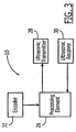
- an apparatus 10 for ultrasonically inspecting a workpiece 12, such as for porosity, microcracking or for thermal damage, is depicted.
- the ultrasonic inspection apparatus can inspect a variety of structures formed of various materials. Structures that may be inspected with an embodiment of an inspection apparatus may include, but are not limited to, composites such as carbon fiber or graphite reinforced epoxy (Gr/Ep) composites or foam filled composites, non-ferromagnetic metals (e.g. aluminum alloy, titanium alloy, or aluminum or titanium hybrid laminates such as GLARE or Ti/Gr), ferromagnetic metals, plastics, ceramics, polymers and virtually all solids, semi-solids and even liquids.
- composites such as carbon fiber or graphite reinforced epoxy (Gr/Ep) composites or foam filled composites
- non-ferromagnetic metals e.g. aluminum alloy, titanium alloy, or aluminum or titanium hybrid laminates such as GLARE or Ti/Gr
- ferromagnetic metals plastics, ceramics, poly
- a structure being inspected may be any myriad of shapes and/or sizes and used in a variety of applications, including aircraft, marine vehicles, automobiles, spacecraft and the like, as well as buildings.
- the structure may be a foam filled hat stiffener or hat stringer.
- the structure may be inspected prior to assembly, such as for porosity, or following assembly, such as for microcracking and/or thermal damage, as described below.
- the ultrasonic inspection apparatus 10 is generally configured for single-sided inspection of the workpiece 12 as a result of its reliance upon backscattered signals. As such, the ultrasonic inspection apparatus is operable to inspect structures in instances in which the opposite side 12b of the structure is inaccessible. For example, the ultrasonic inspection apparatus is operable to inspect structures during manufacture in instances in which the structure is supported upon a mandrel or other tooling with the opposite or back side of the structure facing the mandrel or other tooling. Similarly, the ultrasonic inspection apparatus is operable to inspect structures following deployment even if only a single side 12a is accessible, thereby potentially reducing instances in which the structure must be disassembled and/or removed from the field for inspection.
- the ultrasonic inspection apparatus 10 includes an ultrasonic transmitter that includes one or more ultrasonic transducers 14 oriented in such a manner as to introduce ultrasonic signals that propagate along an axis 16 positioned at an offset angle 18 relative to a predefined reference direction oriented normal to the surface 12a of the structure that faces the inspection apparatus.
- the offset angle may have various predefined values, but is typically an acute, non-zero angle, such as between 5° and 45° and, in one embodiment, between 5° and 15° relative to the predefined reference direction.
- the ultrasonic transmitter may emit ultrasonic signals at any of a plurality of different frequencies. Typically, the frequency of the ultrasonic signals varies in an inverse relationship to the thickness of the workpiece to be inspected.
- the ultrasonic transmitter may transmit signals having a frequency of 10 MHZ for the inspection of thinner structures and a frequency of either 2.25 MHZ or 3.5 MHZ for the inspection of thicker structures. In one embodiment, however, the ultrasonic transmitter emits signals having a frequency of 5 MHZ.
- the ultrasonic transducer 14 is carried by wedge or shoe 20 that defines the offset angle 18.
- the shoe may be formed of various materials, such as materials transparent to ultrasonic signals including, for example, acrylic.
- the ultrasonic transducer may be carried by the shoe in different manners including, for example, a transducer mount for supporting, engaging and orienting the transducer.
- a threaded ring may be mounted to the shoe, such as by a number of screws, and the transducer may be threadably connected to the ring.
- a slip ring may be placed into a groove that is machined into the body of the transducer and the transducer may then be slid into a horizontal gap defined by the shoe.
- a couplant such as an ultrasonic gel or water
- a couplant may be applied between the shoe and the surface 12a of the structure 12 to provide a good path from the transducer into the structure, and possibly as a lubricant for moving the probe over the surface of the structure.
- couplant may be applied between the tranducer and the shoe.
- the shoe may include contact members to support the shoe against the respective surface of the structure.
- a contact member may be any variety of devices capable of supporting the shoe against a surface of a part, including, but not limited to, a wheel, a ball bearing, a fluid bearing, a skid, a tread, or a combination of the aforementioned contact members.
- the ultrasonic inspection apparatus 10 may also include an encoder to record the position of the ultrasonic transducer 14 relative to the workpiece 12 so as to permit the resulting backscattered signals discussed below to be associated with a respective position.
- an encoder to record the position of the ultrasonic transducer 14 relative to the workpiece 12 so as to permit the resulting backscattered signals discussed below to be associated with a respective position.
- Various types of encoders may be employed including, for example, a positional encoder, an optical encoder, a linear encoder, a camera, a directional sensor, or a wheel encoder.
- the transducer(s) 14 and the shoe 20 may be moved manually over the surface 12a of the workpiece 12, the transducers(s) and the shoe may be moved over the surface of the workpiece, such as in a predefined pattern, in an automated or semi-automated fashion.
- the inspection apparatus 10 may include a motor, such as an electronically-controlled stepper motor, that is operably connected to the transducer(s) and the wedge for controllably moving the transducer(s) and the shoe across the surface of the structure.
- the inspection apparatus 10 may include an immersion tank 22 containing a couplant, such as water.
- the transducer(s) may be carried by an arm 24 attached to a robotic scanner, such as the UPKII-T48HD C-Scan system with 3 (x-y-z) motion axis and linear actuator drive, manufactured by NDT Automation.
- the transducer(s) may also be in a phased array format, with an array that is moved along with a robotic arm or manually, such as an Omniscan scanner distributed by Olympus NDT, Inc. Phased array systems allow steering of the ultrasonic beam so an angled beam can be produced without an angled wedge for a transducer shoe.
- Phased array systems could be mounted at an angle for immersion tests as described below or mounted on wedges or shoes for other types of tests.
- the transducer(s) are immersed within the tank so as to be disposed at the desired offset angle relative to the normal to the surface of the structure.
- the robotic scanner may then be configured to move the transducer(s) in a predefined path through the tank so as to interrogate the structure along the predefined path.
- the robotic scanner can be configured to initially place the transducer(s) 14 at a predefined location relative to the workpiece and to then track the motion of the transducer(s) relative to the workpiece.
- a dribbler includes a transducer mounted inside an enclosure with water or other couplant pumped into the enclosure at a rate such that the water or other couplant dribbles out of the bottom of the enclosure so as to provide both a path for the signal and a couplant for the workpiece.
- the inspection apparatus 10 also generally includes a processing element 26, such as a personal computer, a microcontroller, a microprocessor, an application specific integrated circuit (ASIC) or other type of computing device, that serves as a control apparatus for controlling movement of the ultrasonic transmitter 28, e.g., the transducer(s) 14, is scanned in automated or semi-automated embodiments, such as those utilizing a motor or a robot, and for actuating the ultrasonic transmitter in order to generate the ultrasonic signals.
- the inspection apparatus also includes an ultrasonic receiver 30 for receiving the ultrasonic signals that are backscattered by the workpiece 12, such as by the porosity, by microcracks or by the thermal damage as described below.
- the inspection apparatus includes ultrasonic transducer(s) that function as both the ultrasonic transmitters and the ultrasonic receivers.
- the processing element of one embodiment is also configured to receive signals indicative of the position of the transducer(s), such as from an encoder 32 as shown in Figure 3 , a robotic scanner of the like.
- the inspection apparatus 10 is positioned relative to the workpiece 12, such as shown in Figures 1 and 2 , at a predefined location.
- the processing element 26 then actuates the ultrasonic transmitter, such as an ultrasonic transducer 14, to transmit an ultrasonic signal into the workpiece.
- the processing element can actuate the ultrasonic transmitter 28 and in turn, the ultrasonic receiver 30 in various manners
- the processing element of one embodiment includes an ultrasonic pulser receiver module or card for actuating the ultrasonic transmitter and receiver.
- the ultrasonic signals transmitted by the transducer propagate along an axis 16 that is disposed at an offset angle 18 from a normal to the surface 12a of the workpiece.
- a portion of the ultrasonic signals are backscattered as shown by the arcuate lines of Figure 1 , and at least a portion of the backscattered signals are received and detected by the ultrasonic receiver.
- a large defect such as a delamination, a disbond or the like, will not tend to scatter the signals, but will reflect the signals away from the transducer because of the angle.
- the backscattered signals attributable to the interaction of the ultrasonic signals with any single pore, microcrack or any single void or other defect created by thermal damage is relatively small, but measurable.
- the sum of the backscattered signals attributable to a plurality of the pores, a plurality of microcracks or a plurality of the defects attributable to thermal damage at the respective locations is determined, since it is only in the aggregate that the effects of porosity or microcracking or of the defects attributable to thermal damage upon the structure in that location can generally be assessed.
- the processing element 26 generally receives the output from the ultrasonic receiver 30, e.g., one or more transducer(s) 14, over a predefined period of time with the output of the ultrasonic receiver being representative of the amplitude of the signals received by the ultrasonic receiver over the predetermined period of time.
- the processing element includes a digitizer for converting analog signals provided by the ultrasonic receiver to corresponding digital signals.
- the processing element can include a rectifier for rectifying the signals produced by the ultrasonic receiver either prior to or following analog-to-digital conversion.
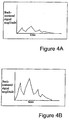
- the digitized and rectified signals representative of the amplitude of the backscattered signals received by the ultrasonic receiver are smaller when a structure having little porosity, few microcracks and little heat damage is suspected.
- the digitized and rectified signals representative of the amplitude of the backscattered signals received by the ultrasonic receiver are larger over time when the structure has more substantial porosity, more microcracks or has suffered heat damage as shown in Figure 4B .
- the processing element may also adjust the signals received from the ultrasonic receiver to remove any contribution, e.g., attenuation, created by the shoe 20.
- the processing element 26 can determine a measure representative of the degree of porosity, microcracking or thermal damage of the workpiece 12 at the respective location. The processing element can then compare the sum of the backscattered signals received by the ultrasonic receiver with a predefined threshold, and the processing element can provide an indication of whether the workpiece at the respective location has an unacceptable degree of porosity, an unacceptable amount of microcracking or an unacceptable amount of thermal damage based upon the relationship of the sum of the backscattered signals received by the ultrasonic receiver to the predefined threshold.
- the predefined threshold is set to a value such that the sum of the backscattered signals received by the ultrasonic receiver over the predefined period at any location is indicative of an unacceptable level of porosity, microcracking or thermal damage if the sum exceeds a predefined threshold. Conversely, if the sum of the backscattered signals received by the ultrasonic receiver is less than the predefined threshold, the workpiece will generally be found to have acceptable levels of porosity, microcracking and thermal damage at the respective location.
- the value of the predefined threshold may vary, depending upon the application, the loads that are anticipated to be placed upon the workpiece and the tolerance of the workpiece and/or the application to the structural degradation occasioned by porosity, microcracking or thermal damage, among other factors.
- the predefined threshold may be defined in various manners, the predefined threshold may be determined by inspecting several samples constructed of the same materials and in the same thickness and configuration as the workpiece 12, but having different known levels of porosity, microcracking and/or thermal damage - some of which being known to be acceptable and others of which being known to be unacceptable. By comparing the measure representative of the degree of porosity, microcracking or thermal damage for each of the samples and determining those measures that are reflective of acceptable samples and those reflective of unacceptable samples, the threshold representative of the dividing line between acceptable and unacceptable levels of porosity, microcracking or thermal damage may be predefined.
- the predetermined time period over which the backscattered signals received by the ultrasonic receiver 30 are summed generally corresponds to the thickness of the workpiece 12 or, at least, the thickness of the portion of the workpiece that is desirably inspected.
- the predetermined time period is generally set to equal or slightly exceed the time required for ultrasonic signals to propagate through the workpiece or at least that portion of the workpiece that is desired to be inspected and to then return to the ultrasonic receiver. While the predetermined time period can have a wide range of values depending upon the thickness of the workpiece or at least the thickness of that portion of the workpiece that is desirably inspected, the predetermined time period is typically one to a few microseconds.
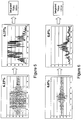
- the leftmost graphs in Figures 5 and 6 illustrate the digitized output of an ultrasonic receiver 30 in terms of the relative ultrasonic amplitude of the backscattered signals over a period of 350 microseconds during the inspection of structures having a porosity of 6.15% and 0%, respectively.
- the relative ultrasonic amplitude of the backscattered signals represent the voltage produced by the piezoelectric transducer of the ultrasonic receiver as the ultrasonic (stress) waves impinge upon the face of the transducer.
- the relative ultrasonic amplitude is typically measured in digitizer units with the actual voltage being unimportant so long as no changes are made to the ultrasonic transmitter and receiver during a test.
- Figures 5 and 6 depict the same output following rectification.
- a measure of 39,043 is obtained for the structure having a porosity of 6.15% and a measure of 13, 116 is obtained for the structure having a porosity of 0%.
- Figures 5 and 6 graphically illustrate the relationship between the area under the curve and the porosity (or likewise, microcracking or thermal damage) of a structure.
- the propagation of the ultrasonic signals at an offset angle relative to the normal to the surface of the workpiece also advantageously permits the ultrasonic inspection apparatus to obtain reliable results indicative of the porosity, microcracking or thermal damage of the workpiece.
- the backscattered signals received by the ultrasonic receiver are not washed out or otherwise rendered insignificant as a result of the receipt of reflected signals having a larger, sometimes much larger, amplitude.
- the ultrasonic inspection apparatus 10 and, in particular, the ultrasonic transmitter 28 initially transmits ultrasonic signals into the workpiece 12 at an initial location and the ultrasonic receiver 30 receives backscattered signals over a predetermined period of time.
- the ultrasonic transmitter and receiver e.g., the ultrasonic transducer(s) 14 and shoe 20
- the ultrasonic transmitter and receiver may be moved along the surface 12a of the workpiece to a second position and the process of injecting ultrasonic signals and receiving the backscattered signals over a predetermined period of time can be repeated.
- This iterative process can be repeated any number of times as the ultrasonic transmitter and receiver, e.g., the ultrasonic transducer(s), are moved, typically in a predefined pattern, along the surface of the workpiece.
- the results of the inspection can be processed in many different manners. For example, the sum of the amplitude of the backscattered signals within a predefined period of time at each respective location can be stored and then analyzed to identify location(s) which would appear to have an undesirable amount of porosity, microcracking or thermal damage.
- the inspection apparatus 10 can transmit the data, such as in either a wireline or wireless manner, to another computing device for subsequent analysis, such as to identify location(s) which would appear to have an undesirable amount of porosity, microcracking or thermal damage.
- the processing element 26 of the ultrasonic inspection apparatus can compare the sum of the amplitude of the backscattered signals received by the ultrasonic receiver 30 over a predetermined period of time at each location and provide a warning, an alarm or the like to the operator of the inspection apparatus during the course of the inspection of any location(s) that appear to have an unacceptable degree of porosity, microcracking or thermal damage.
- the results can be presented in a variety of manners, including in a numerical format representative of the sum of the amplitudes of the backscattered signals over a predetermined period of time at the different locations or graphically in which the sums of the amplitudes of the backscattered signals at each location are graphically depicted.
- the ultrasonic inspection apparatus 10 can be deployed for various applications, including the inspection of a workpiece 12 during manufacture, in which case the ultrasonic inspection apparatus would generally inspect the workpiece for porosity, or following placement of the workpiece into service in the field, in which instances the ultrasonic inspection apparatus would generally inspect the workpiece for the effects of microcracking or thermal damage.
- the ultrasonic inspection apparatus is generally capable of injecting the ultrasonic signals into the workpiece and receiving the backscattered signals from the workpiece, even in instances in which the surface of the workpiece that faces the ultrasonic inspection apparatus has been primed, painted or includes lightening strike protection.
- Ultrasonic inspection can be performed of structures that have been primed, painted or include lightening strike protection because these features will only slightly attenuate the ultrasonic signal. If a feature, such as paint, is thin compared to the wavelength of the ultrasound signals and/or the impedance mismatch at the boundaries is small, the ultrasound signals will tend to penetrate through the feature. A large impedance mismatch, such as between a material and air, will cause a very strong reflection at the boundary, and only a small percentage of the ultrasonic signal will penetrate the material. This larger impedence mismatch is what leads to the general use of a coupant between the transducer 14 and the workpiece 12.
- the inspection apparatus of embodiments of the present invention is particularly suitable for inspecting workpieces in the field following the application of primer, paint and/or lightening strike protection.
Landscapes
- Physics & Mathematics (AREA)
- Health & Medical Sciences (AREA)
- Life Sciences & Earth Sciences (AREA)
- Chemical & Material Sciences (AREA)
- Analytical Chemistry (AREA)
- Biochemistry (AREA)
- General Health & Medical Sciences (AREA)
- General Physics & Mathematics (AREA)
- Immunology (AREA)
- Pathology (AREA)
- Acoustics & Sound (AREA)
- Engineering & Computer Science (AREA)
- Signal Processing (AREA)
- Investigating Or Analyzing Materials By The Use Of Ultrasonic Waves (AREA)
Claims (8)
- Verfahren zum Inspizieren eines Werkstücks (12), das aufweist:Einführen von Ultraschallsignalen in das Werkstück (12) entlang einer vordefinierten Achse (16) einer Ausbreitung, die in einem spitzen Versatzwinkel (18) ungleich Null relativ zu einer vordefinierten Referenzrichtung orientiert ist, die normal zum Werkstück (12) orientiert ist;Empfangen rückgestreuter Signale vom Werkstück (12) in Reaktion auf die Ultraschallsignale;Bestimmen eines Maßes, das für die kumulative Energie der zurückgestreuten Signale repräsentativ ist, die über ein vordefinierte Zeitinterval empfangen werden, indem die Energie der zurückgestreuten Signale, die über das vordefinierte Zeitinterval empfangen werden, integriert wird, wobei das vordefinierte Zeitinterval allgemein gleich der Zeit oder leicht darüber eingestellt wird, die Ultraschallsignale brauchen, um sich durch das Werkstück oder durch zumindest den Abschnitt des Werkstücks auszubreiten, der zu inspizieren ist, und um dann zum Ultraschallempfänger zurückzukehren; undBestimmen, ob es eine anomale Antwort vom Werkstück (12) gibt oder nicht basierend auf dem Maß, das für die kumulative Energie der zurückgestreuten Signale repräsentativ ist, im Vergleich zu einem vordefinierten Schwellenwert.
- Verfahren nach Anspruch 1, wobei ein Einführen der Ultraschallsignale ein Einführen der Ultraschallsignale bei einem Versatzwinkel (18) zwischen 5° und 45° relativ zur vordefinierten Referenzrichtung aufweist.
- Verfahren nach Anspruch 1, wobei ein Einführen von Ultraschallsignalen in das Werkstück (12) und ein Empfangen von Ultraschallsignalen vom Werkstück (12) bei einer Vielzahl von Orten wiederholt wird, die über das Werkstück (12) verteilt sind.
- Inspektionsvcarrichtung (10), die aufweist:einen Ultraschallsender (28), der zum Einführen von Ultraschallsignalen in das Werkstück (12) entlang einer vordefinierten Achse (16) einer Ausbreitung eingerichtet ist, die in einem spitzen Versatzwinkel (18) ungleich Null relativ zu einer vordefinierten Referenzrichtung orientiert ist, die normal zum Werkstück (12) orientiert ist;einen tJltraschallempfänger (30), der zum Empfangen von zurückgestreuten Signalen von dem Werkstück (12) in Reaktion auf die Ultraschallsignale eingerichtet ist, wobei das vordefinierte Zeitinterval im Allgemeinen gleich oder leicht größer als die Zeit eingestellt wird, die Ultraschallsignale brauchen, um sich durch das Werkstück (12) oder durch zumindest einen Abschnitt des Werkstücks (12) auszubreiten, der zu inspizieren ist, und um dann zum Ultraschallempfänger zurückzukehren; undein Verarbeitungselement (26), das zum Bestimmen eines Maßes eingerichtet ist, das für eine kumulative Energie der zurückgestreuten Signale repräsentativ ist, indem die Energie der zurückgestreuten Signale, die über ein vordefiniertes Zeitinterval empfangen werden, integriert wird, und zum Bestimmen eingerichtet ist, ob es eine anormale Antwort vom Werkstück (12) gibt oder nicht basierend auf dem Maß, das für die kumulative Energie der zurückgestreuten Signale repräsentativ ist, im Vergleich zu einem vordefinierten Schwellenwert.
- fnspekfiionsvorrichtung nach Anspruch 4, wobei der Ultraschallsender (28) eingerichtet ist, die Ultraschallsignale in einem Versatzwinkel (18) zwischen 5° und 45° relativ zur vordefinierten Referenzrichtung einzuführen.
- lnspektionsvorrichtung nach Anspruch 4, die des Weiteren einen Schuh aufweist, der den Versatzwinkel definiert und der zumindest Abschnitte des Ultraschallsenders trägt.
- Inspektionsvorrichtung nach Anspruch 6, wobei der Ultraschallsender (28), der durch den Schuh (20) getragen wird, zumindest einen Ultraschall-Transducer (14) aufweist, und wobei der Schuh (20) einen angewinkelten Schuh aufweist.
- Inspektionsvorrichtung nach Anspruch 6, wobei der Ultraschallsender (28), der durch den Schuh (20) getragen wird, eine phasengesteuerte Gruppe von Ultraschall-Transducern (14) aufweist.
Applications Claiming Priority (2)
| Application Number | Priority Date | Filing Date | Title |
|---|---|---|---|
| US11/687,950 US7757558B2 (en) | 2007-03-19 | 2007-03-19 | Method and apparatus for inspecting a workpiece with angularly offset ultrasonic signals |
| PCT/US2008/057165 WO2008115839A1 (en) | 2007-03-19 | 2008-03-14 | Method and apparatus for inspecting a workpiece with angularly offset ultrasonic signals |
Publications (2)
| Publication Number | Publication Date |
|---|---|
| EP2126559A1 EP2126559A1 (de) | 2009-12-02 |
| EP2126559B1 true EP2126559B1 (de) | 2016-05-25 |
Family
ID=39410276
Family Applications (1)
| Application Number | Title | Priority Date | Filing Date |
|---|---|---|---|
| EP08732312.7A Not-in-force EP2126559B1 (de) | 2007-03-19 | 2008-03-14 | Verfahren und vorrichtung zur inspektion eines werkstücks mit winkelversetzten ultraschallsignalen |
Country Status (3)
| Country | Link |
|---|---|
| US (1) | US7757558B2 (de) |
| EP (1) | EP2126559B1 (de) |
| WO (1) | WO2008115839A1 (de) |
Families Citing this family (42)
| Publication number | Priority date | Publication date | Assignee | Title |
|---|---|---|---|---|
| US7938008B2 (en) * | 2006-11-28 | 2011-05-10 | Fbs, Inc. | Non-destructive examination apparatus and method for guided waves |
| US20090062724A1 (en) * | 2007-08-31 | 2009-03-05 | Rixen Chen | System and apparatus for sonodynamic therapy |
| US7712369B2 (en) * | 2007-11-27 | 2010-05-11 | The Boeing Company | Array-based system and method for inspecting a workpiece with backscattered ultrasonic signals |
| DE102008041831A1 (de) * | 2008-09-05 | 2010-03-25 | Ge Inspection Technologies Gmbh | Impulsechoverfahren mit Ermittlung der Vorlaufkörpergeometrie |
| US8286488B2 (en) * | 2009-05-01 | 2012-10-16 | General Electric Company | Apparatus and system for measuring material thickness |
| ES2761264T3 (es) * | 2009-05-14 | 2020-05-19 | Ge Sensing & Inspection Tech | Método de fabricación de una sonda de ensayo y un dispositivo de ensayo para el ensayo ultrasónico no destructivo de una pieza de trabajo |
| US8522614B2 (en) * | 2010-05-26 | 2013-09-03 | General Electric Company | In-line inspection methods and closed loop processes for the manufacture of prepregs and/or laminates comprising the same |
| US8333115B1 (en) | 2010-08-26 | 2012-12-18 | The Boeing Company | Inspection apparatus and method for irregular shaped, closed cavity structures |
| US8826740B2 (en) * | 2011-08-02 | 2014-09-09 | General Electric Company | Methods and apparatus for porosity measurement and defect detection |
| US8833169B2 (en) * | 2011-12-09 | 2014-09-16 | General Electric Company | System and method for inspection of a part with dual multi-axis robotic devices |
| US9709514B2 (en) * | 2012-04-02 | 2017-07-18 | The Boeing Company | X-ray backscatter system and method for detecting discrepancies in items |
| JP5916864B2 (ja) * | 2012-07-31 | 2016-05-11 | 株式会社Ihiインフラシステム | 未溶着量の測定方法及び超音波探傷装置 |
| US9435770B2 (en) | 2012-12-06 | 2016-09-06 | General Electric Company | Method of making a flexible delay line, a flexible delay line and a transducer |
| US9360459B2 (en) * | 2013-05-17 | 2016-06-07 | The Boeing Company | Porosity inspection system for composite structure with non-parallel surfaces |
| US9787916B2 (en) | 2014-10-28 | 2017-10-10 | The Boeing Company | Active real-time characterization system |
| US10641739B2 (en) | 2014-12-23 | 2020-05-05 | Trustees Of Boston University | Method and system for oblique backscattering ultrasound transmissive contrast imaging |
| JP6682913B2 (ja) * | 2016-02-29 | 2020-04-15 | 株式会社Ihi | 損傷評価装置および損傷評価方法 |
| JP6182236B1 (ja) * | 2016-04-25 | 2017-08-16 | 非破壊検査株式会社 | 積層体の剥離検査方法及び剥離検査装置 |
| JP6430443B2 (ja) * | 2016-07-01 | 2018-11-28 | 非破壊検査株式会社 | 検査対象物の非露出部の腐食検査方法及び腐食検査装置 |
| JP6799982B2 (ja) * | 2016-09-26 | 2020-12-16 | 神鋼検査サービス株式会社 | 線状体の異常検知方法および異常検知装置、ならびに線状体の異常検知装置に用いられる治具 |
| US10424056B2 (en) | 2018-02-22 | 2019-09-24 | The Boeing Company | Active real-time characterization system for monitoring absorption and curing rates of chemical substances |
| US10578562B2 (en) | 2018-02-22 | 2020-03-03 | The Boeing Company | Active real-time characterization system using radio-frequency radiation |
| US10430936B2 (en) | 2018-02-22 | 2019-10-01 | The Boeing Company | Active real-time characterization system for identifying surface contamination |
| US10438337B2 (en) | 2018-02-22 | 2019-10-08 | The Boeing Company | Active real-time characterization system utilizing beam scanning for surface imaging |
| US10424057B2 (en) | 2018-02-22 | 2019-09-24 | The Boeing Company | Active real-time characterization system for detecting physical imperfections during semiconductor manufacturing |
| US10712265B2 (en) | 2018-02-22 | 2020-07-14 | The Boeing Company | Active real-time characterization system providing spectrally broadband characterization |
| US10685433B2 (en) | 2018-05-04 | 2020-06-16 | Raytheon Technologies Corporation | Nondestructive coating imperfection detection system and method therefor |
| US10488371B1 (en) * | 2018-05-04 | 2019-11-26 | United Technologies Corporation | Nondestructive inspection using thermoacoustic imagery and method therefor |
| US10958843B2 (en) | 2018-05-04 | 2021-03-23 | Raytheon Technologies Corporation | Multi-camera system for simultaneous registration and zoomed imagery |
| US10473593B1 (en) | 2018-05-04 | 2019-11-12 | United Technologies Corporation | System and method for damage detection by cast shadows |
| US11079285B2 (en) | 2018-05-04 | 2021-08-03 | Raytheon Technologies Corporation | Automated analysis of thermally-sensitive coating and method therefor |
| US11268881B2 (en) | 2018-05-04 | 2022-03-08 | Raytheon Technologies Corporation | System and method for fan blade rotor disk and gear inspection |
| US10914191B2 (en) | 2018-05-04 | 2021-02-09 | Raytheon Technologies Corporation | System and method for in situ airfoil inspection |
| US10928362B2 (en) | 2018-05-04 | 2021-02-23 | Raytheon Technologies Corporation | Nondestructive inspection using dual pulse-echo ultrasonics and method therefor |
| US10902664B2 (en) | 2018-05-04 | 2021-01-26 | Raytheon Technologies Corporation | System and method for detecting damage using two-dimensional imagery and three-dimensional model |
| US10943320B2 (en) | 2018-05-04 | 2021-03-09 | Raytheon Technologies Corporation | System and method for robotic inspection |
| CN111351851B (zh) * | 2018-12-20 | 2023-03-31 | 核动力运行研究所 | 一种超声信号往复错位智能识别及信号校准方法 |
| JP7261093B2 (ja) * | 2019-06-06 | 2023-04-19 | 一般財団法人電力中央研究所 | 金属溶接部の損傷評価装置 |
| CA3156962A1 (en) * | 2019-11-01 | 2021-05-06 | Jacques L. Brignac | Ultrasonic testing apparatus with couplant delivery system |
| CN111060602A (zh) * | 2019-11-29 | 2020-04-24 | 中国科学院金属研究所 | 一种SiC/Al复合材料超声检测缺陷的定性和定量分析方法 |
| US12498353B2 (en) * | 2020-08-18 | 2025-12-16 | Chevron U.S.A. Inc. | Detecting surface cracks using acoustic signals |
| CN117280203A (zh) | 2021-05-13 | 2023-12-22 | 圣戈本陶瓷及塑料股份有限公司 | 用于检查物体的方法和系统 |
Citations (2)
| Publication number | Priority date | Publication date | Assignee | Title |
|---|---|---|---|---|
| US5390544A (en) * | 1993-07-16 | 1995-02-21 | The United States Of America As Represented By The Administrator Of The National Aeronautics And Space Administration | Method and apparatus for non-destructive evaluation of composite materials with cloth surface impressions |
| JP2003130854A (ja) * | 2001-10-22 | 2003-05-08 | Chubu Electric Power Co Inc | 配管検査方法及び配管検査装置 |
Family Cites Families (35)
| Publication number | Priority date | Publication date | Assignee | Title |
|---|---|---|---|---|
| US3712119A (en) * | 1970-01-30 | 1973-01-23 | Automation Ind Inc | Material tester |
| GB1474932A (en) | 1975-03-13 | 1977-05-25 | Lloyds Register Of Shipping Tr | Ultrasonic probe |
| US4058003A (en) * | 1976-07-21 | 1977-11-15 | The Board Of Trustees Of The Leland Stanford Junior University | Ultrasonic electronic lens with reduced delay range |
| DE3134482A1 (de) * | 1981-09-01 | 1983-03-31 | Hoesch Werke Ag, 4600 Dortmund | Verfahren zur automatischen fertigungskontrolle langgestreckter werkstuecke |
| US4596145A (en) * | 1983-09-20 | 1986-06-24 | Smith Stephen W | Acoustic orthoscopic imaging system |
| US4591511A (en) * | 1984-07-30 | 1986-05-27 | The United States Of America As Represented By The Secretary Of The Navy | Adhesive repair patch |
| GB8423023D0 (en) * | 1984-09-12 | 1984-10-17 | Short Brothers Ltd | Ultrasonic scanning system |
| FR2615288B1 (fr) * | 1987-05-12 | 1989-09-22 | Commissariat Energie Atomique | Procede automatique d'identification de defauts par ultrasons et systeme correspondant |
| DE3789869T2 (de) * | 1987-06-08 | 1994-12-22 | Hitachi Construction Machinery | Verfahren zur messung der tiefe von oberflächenunebenheitsfehlern eines festen materials unter verwendung von ultraschallwellen. |
| US5091893A (en) * | 1990-04-05 | 1992-02-25 | General Electric Company | Ultrasonic array with a high density of electrical connections |
| US5073814A (en) * | 1990-07-02 | 1991-12-17 | General Electric Company | Multi-sublayer dielectric layers |
| US5165270A (en) * | 1990-12-31 | 1992-11-24 | Sansalone Mary J | Non-destructive materials testing apparatus and technique for use in the field |
| US5614670A (en) * | 1993-10-29 | 1997-03-25 | Board Of Regents, The University Of Texas System | Movable seismic pavement analyzer |
| US5735282A (en) * | 1996-05-30 | 1998-04-07 | Acuson Corporation | Flexible ultrasonic transducers and related systems |
| US5680863A (en) * | 1996-05-30 | 1997-10-28 | Acuson Corporation | Flexible ultrasonic transducers and related systems |
| US5814731A (en) * | 1997-01-28 | 1998-09-29 | Alexander; Alton Michel | Ultrasonic scanning apparatus for nondestructive site characterization of structures using a planar based acoustic transmitter and receiver in a rolling pond |
| US5983701A (en) * | 1997-06-13 | 1999-11-16 | The Royal Institution For The Advancement Of Learning | Non-destructive evaluation of geological material structures |
| US6586702B2 (en) * | 1997-09-25 | 2003-07-01 | Laser Electro Optic Application Technology Company | High density pixel array and laser micro-milling method for fabricating array |
| CA2276319C (en) * | 1997-10-31 | 2006-03-28 | Kawasaki Steel Corporation | Method and apparatus for ultrasonically testing of the surface of columnar structures, and method for grinding rolls by use of them |
| US6777931B1 (en) * | 1998-05-12 | 2004-08-17 | Kawasaki Steel Corporation | Method of displaying signal obtained by measuring probe and device therefor |
| FR2786651B1 (fr) * | 1998-11-27 | 2002-10-25 | Commissariat Energie Atomique | Transducteur ultrasonore de contact, a elements multiples |
| US6234025B1 (en) * | 1999-03-29 | 2001-05-22 | Sandia Corporation | Ultrasonic inspection apparatus and method using a focused wave device |
| JP3670525B2 (ja) * | 1999-08-04 | 2005-07-13 | 旭化成エンジニアリング株式会社 | 円筒タンク底板の板厚測定装置 |
| US6822374B1 (en) * | 2000-11-15 | 2004-11-23 | General Electric Company | Multilayer piezoelectric structure with uniform electric field |
| US6598485B1 (en) * | 2000-11-24 | 2003-07-29 | Sinotech Engineering Consultants, Inc. | Method and device for evaluating quality of concrete structures |
| US6476541B1 (en) * | 2001-02-23 | 2002-11-05 | General Electric Company | Optically controlled ultrasonic sensor |
| US20020128790A1 (en) * | 2001-03-09 | 2002-09-12 | Donald Woodmansee | System and method of automated part evaluation including inspection, disposition recommendation and refurbishment process determination |
| US20040123665A1 (en) * | 2001-04-11 | 2004-07-01 | Blodgett David W. | Nondestructive detection of reinforcing member degradation |
| US6681466B2 (en) * | 2001-05-09 | 2004-01-27 | United Air Lines, Inc. | Router replacement method |
| US6656124B2 (en) * | 2001-10-15 | 2003-12-02 | Vermon | Stack based multidimensional ultrasonic transducer array |
| US6591679B2 (en) * | 2001-11-14 | 2003-07-15 | Electric Power Research Institute, Inc. | Method for sizing surface breaking discontinuities with ultrasonic imaging |
| US6948369B2 (en) * | 2002-02-06 | 2005-09-27 | Applied Metrics, Inc. | Methods for ultrasonic inspection of spot and seam resistance welds in metallic sheets and a spot weld examination probe system (SWEPS) |
| US20060004499A1 (en) * | 2004-06-30 | 2006-01-05 | Angela Trego | Structural health management architecture using sensor technology |
| US20060186260A1 (en) * | 2005-02-18 | 2006-08-24 | American Airlines, Inc. | Method of inspecting aircraft |
| US7520172B2 (en) * | 2005-09-07 | 2009-04-21 | The Boeing Company | Inspection system for inspecting a structure and associated method |
-
2007
- 2007-03-19 US US11/687,950 patent/US7757558B2/en not_active Expired - Fee Related
-
2008
- 2008-03-14 EP EP08732312.7A patent/EP2126559B1/de not_active Not-in-force
- 2008-03-14 WO PCT/US2008/057165 patent/WO2008115839A1/en not_active Ceased
Patent Citations (2)
| Publication number | Priority date | Publication date | Assignee | Title |
|---|---|---|---|---|
| US5390544A (en) * | 1993-07-16 | 1995-02-21 | The United States Of America As Represented By The Administrator Of The National Aeronautics And Space Administration | Method and apparatus for non-destructive evaluation of composite materials with cloth surface impressions |
| JP2003130854A (ja) * | 2001-10-22 | 2003-05-08 | Chubu Electric Power Co Inc | 配管検査方法及び配管検査装置 |
Also Published As
| Publication number | Publication date |
|---|---|
| US7757558B2 (en) | 2010-07-20 |
| EP2126559A1 (de) | 2009-12-02 |
| WO2008115839A1 (en) | 2008-09-25 |
| US20080229834A1 (en) | 2008-09-25 |
Similar Documents
| Publication | Publication Date | Title |
|---|---|---|
| EP2126559B1 (de) | Verfahren und vorrichtung zur inspektion eines werkstücks mit winkelversetzten ultraschallsignalen | |
| US7712369B2 (en) | Array-based system and method for inspecting a workpiece with backscattered ultrasonic signals | |
| Shen et al. | Ultrasonic NDE techniques for impact damage inspection on CFRP laminates | |
| GB2482588A (en) | Ultrasonic probe | |
| US11860131B2 (en) | System and method for portable ultrasonic testing | |
| US20090249879A1 (en) | Inspection systems and methods for detection of material property anomalies | |
| AU2009246272B2 (en) | Method and apparatus for spectroscopic characterization of samples using a laser-ultrasound system | |
| Zaiß et al. | Use of thermography and ultrasound for the quality control of SMC lightweight material reinforced by carbon fiber tapes | |
| Tiwari et al. | Comparative analysis of non-contact ultrasonic methods for defect estimation of composites in remote areas | |
| EP2984479B1 (de) | Ultraschallprüfung unter verwendung von einfallswinkeln | |
| Djordjevic | Ultrasonic characterization of advanced composite materials | |
| US20080236288A1 (en) | Inspection systems and methods for detection of material property anomalies | |
| Zhong et al. | Ultrasonic testing techniques for nondestructive evaluation of fiber-reinforced composite structures | |
| Baid et al. | Detection of disbonds in a honeycomb composite structure using guided waves | |
| Vyas et al. | A review on nondestructive techniques and characteristics of composite materials for the aerospace system | |
| Tallafuss et al. | A feasibility study on different NDT techniques used for testing bond quality in cold roll bonded Al-Sn alloy/steel bimetal strips | |
| Marsh | Finding flaws in composites | |
| CN113820397B (zh) | 利用使用信号积分的超声测试的死区检查 | |
| Azimi et al. | Nondestructive thickness mapping of corroded plate structures using guided lamb wave propagation | |
| Zhang et al. | Ultrasonic Beam Profile Characteristics for Surface Defect Detection in Mobility Components | |
| Tallafuss et al. | A comparison study on different NDT techniques used for testing bond quality in cold roll bonded AlSn alloy/steel bimetal strips | |
| Komsky | Ultrasonic imaging of hidden defects using dry-coupled ultrasonic probes | |
| Srinivasa | Investigation of surface roughness for metal matrix composites using ultrasonic testing | |
| Schlengermann | Application of Images When Evaluating Ultrasonic Examination: Results in Industrial Practice | |
| Roach et al. | Detection of Small Corrosion Levels in Multi-Layered Joints. |
Legal Events
| Date | Code | Title | Description |
|---|---|---|---|
| PUAI | Public reference made under article 153(3) epc to a published international application that has entered the european phase |
Free format text: ORIGINAL CODE: 0009012 |
|
| 17P | Request for examination filed |
Effective date: 20090622 |
|
| AK | Designated contracting states |
Kind code of ref document: A1 Designated state(s): AT BE BG CH CY CZ DE DK EE ES FI FR GB GR HR HU IE IS IT LI LT LU LV MC MT NL NO PL PT RO SE SI SK TR |
|
| DAX | Request for extension of the european patent (deleted) | ||
| 17Q | First examination report despatched |
Effective date: 20110926 |
|
| GRAP | Despatch of communication of intention to grant a patent |
Free format text: ORIGINAL CODE: EPIDOSNIGR1 |
|
| RIC1 | Information provided on ipc code assigned before grant |
Ipc: G01N 29/26 20060101AFI20151209BHEP Ipc: G01N 29/04 20060101ALI20151209BHEP Ipc: G01N 29/22 20060101ALI20151209BHEP Ipc: G01N 29/44 20060101ALI20151209BHEP |
|
| INTG | Intention to grant announced |
Effective date: 20160108 |
|
| GRAS | Grant fee paid |
Free format text: ORIGINAL CODE: EPIDOSNIGR3 |
|
| GRAA | (expected) grant |
Free format text: ORIGINAL CODE: 0009210 |
|
| AK | Designated contracting states |
Kind code of ref document: B1 Designated state(s): AT BE BG CH CY CZ DE DK EE ES FI FR GB GR HR HU IE IS IT LI LT LU LV MC MT NL NO PL PT RO SE SI SK TR |
|
| REG | Reference to a national code |
Ref country code: GB Ref legal event code: FG4D |
|
| REG | Reference to a national code |
Ref country code: CH Ref legal event code: EP |
|
| REG | Reference to a national code |
Ref country code: IE Ref legal event code: FG4D Ref country code: AT Ref legal event code: REF Ref document number: 802711 Country of ref document: AT Kind code of ref document: T Effective date: 20160615 |
|
| REG | Reference to a national code |
Ref country code: DE Ref legal event code: R096 Ref document number: 602008044410 Country of ref document: DE |
|
| REG | Reference to a national code |
Ref country code: LT Ref legal event code: MG4D |
|
| REG | Reference to a national code |
Ref country code: NL Ref legal event code: MP Effective date: 20160525 |
|
| PG25 | Lapsed in a contracting state [announced via postgrant information from national office to epo] |
Ref country code: NL Free format text: LAPSE BECAUSE OF FAILURE TO SUBMIT A TRANSLATION OF THE DESCRIPTION OR TO PAY THE FEE WITHIN THE PRESCRIBED TIME-LIMIT Effective date: 20160525 Ref country code: FI Free format text: LAPSE BECAUSE OF FAILURE TO SUBMIT A TRANSLATION OF THE DESCRIPTION OR TO PAY THE FEE WITHIN THE PRESCRIBED TIME-LIMIT Effective date: 20160525 Ref country code: LT Free format text: LAPSE BECAUSE OF FAILURE TO SUBMIT A TRANSLATION OF THE DESCRIPTION OR TO PAY THE FEE WITHIN THE PRESCRIBED TIME-LIMIT Effective date: 20160525 Ref country code: NO Free format text: LAPSE BECAUSE OF FAILURE TO SUBMIT A TRANSLATION OF THE DESCRIPTION OR TO PAY THE FEE WITHIN THE PRESCRIBED TIME-LIMIT Effective date: 20160825 |
|
| REG | Reference to a national code |
Ref country code: AT Ref legal event code: MK05 Ref document number: 802711 Country of ref document: AT Kind code of ref document: T Effective date: 20160525 |
|
| PG25 | Lapsed in a contracting state [announced via postgrant information from national office to epo] |
Ref country code: ES Free format text: LAPSE BECAUSE OF FAILURE TO SUBMIT A TRANSLATION OF THE DESCRIPTION OR TO PAY THE FEE WITHIN THE PRESCRIBED TIME-LIMIT Effective date: 20160525 Ref country code: PT Free format text: LAPSE BECAUSE OF FAILURE TO SUBMIT A TRANSLATION OF THE DESCRIPTION OR TO PAY THE FEE WITHIN THE PRESCRIBED TIME-LIMIT Effective date: 20160926 Ref country code: SE Free format text: LAPSE BECAUSE OF FAILURE TO SUBMIT A TRANSLATION OF THE DESCRIPTION OR TO PAY THE FEE WITHIN THE PRESCRIBED TIME-LIMIT Effective date: 20160525 Ref country code: HR Free format text: LAPSE BECAUSE OF FAILURE TO SUBMIT A TRANSLATION OF THE DESCRIPTION OR TO PAY THE FEE WITHIN THE PRESCRIBED TIME-LIMIT Effective date: 20160525 Ref country code: GR Free format text: LAPSE BECAUSE OF FAILURE TO SUBMIT A TRANSLATION OF THE DESCRIPTION OR TO PAY THE FEE WITHIN THE PRESCRIBED TIME-LIMIT Effective date: 20160826 Ref country code: LV Free format text: LAPSE BECAUSE OF FAILURE TO SUBMIT A TRANSLATION OF THE DESCRIPTION OR TO PAY THE FEE WITHIN THE PRESCRIBED TIME-LIMIT Effective date: 20160525 |
|
| PG25 | Lapsed in a contracting state [announced via postgrant information from national office to epo] |
Ref country code: EE Free format text: LAPSE BECAUSE OF FAILURE TO SUBMIT A TRANSLATION OF THE DESCRIPTION OR TO PAY THE FEE WITHIN THE PRESCRIBED TIME-LIMIT Effective date: 20160525 Ref country code: DK Free format text: LAPSE BECAUSE OF FAILURE TO SUBMIT A TRANSLATION OF THE DESCRIPTION OR TO PAY THE FEE WITHIN THE PRESCRIBED TIME-LIMIT Effective date: 20160525 Ref country code: RO Free format text: LAPSE BECAUSE OF FAILURE TO SUBMIT A TRANSLATION OF THE DESCRIPTION OR TO PAY THE FEE WITHIN THE PRESCRIBED TIME-LIMIT Effective date: 20160525 Ref country code: CZ Free format text: LAPSE BECAUSE OF FAILURE TO SUBMIT A TRANSLATION OF THE DESCRIPTION OR TO PAY THE FEE WITHIN THE PRESCRIBED TIME-LIMIT Effective date: 20160525 Ref country code: SK Free format text: LAPSE BECAUSE OF FAILURE TO SUBMIT A TRANSLATION OF THE DESCRIPTION OR TO PAY THE FEE WITHIN THE PRESCRIBED TIME-LIMIT Effective date: 20160525 |
|
| PG25 | Lapsed in a contracting state [announced via postgrant information from national office to epo] |
Ref country code: BE Free format text: LAPSE BECAUSE OF FAILURE TO SUBMIT A TRANSLATION OF THE DESCRIPTION OR TO PAY THE FEE WITHIN THE PRESCRIBED TIME-LIMIT Effective date: 20160525 Ref country code: PL Free format text: LAPSE BECAUSE OF FAILURE TO SUBMIT A TRANSLATION OF THE DESCRIPTION OR TO PAY THE FEE WITHIN THE PRESCRIBED TIME-LIMIT Effective date: 20160525 Ref country code: AT Free format text: LAPSE BECAUSE OF FAILURE TO SUBMIT A TRANSLATION OF THE DESCRIPTION OR TO PAY THE FEE WITHIN THE PRESCRIBED TIME-LIMIT Effective date: 20160525 |
|
| REG | Reference to a national code |
Ref country code: DE Ref legal event code: R097 Ref document number: 602008044410 Country of ref document: DE |
|
| REG | Reference to a national code |
Ref country code: FR Ref legal event code: PLFP Year of fee payment: 10 |
|
| PLBE | No opposition filed within time limit |
Free format text: ORIGINAL CODE: 0009261 |
|
| STAA | Information on the status of an ep patent application or granted ep patent |
Free format text: STATUS: NO OPPOSITION FILED WITHIN TIME LIMIT |
|
| 26N | No opposition filed |
Effective date: 20170228 |
|
| PG25 | Lapsed in a contracting state [announced via postgrant information from national office to epo] |
Ref country code: SI Free format text: LAPSE BECAUSE OF FAILURE TO SUBMIT A TRANSLATION OF THE DESCRIPTION OR TO PAY THE FEE WITHIN THE PRESCRIBED TIME-LIMIT Effective date: 20160525 |
|
| REG | Reference to a national code |
Ref country code: CH Ref legal event code: PL |
|
| PG25 | Lapsed in a contracting state [announced via postgrant information from national office to epo] |
Ref country code: MC Free format text: LAPSE BECAUSE OF FAILURE TO SUBMIT A TRANSLATION OF THE DESCRIPTION OR TO PAY THE FEE WITHIN THE PRESCRIBED TIME-LIMIT Effective date: 20160525 |
|
| REG | Reference to a national code |
Ref country code: IE Ref legal event code: MM4A |
|
| PG25 | Lapsed in a contracting state [announced via postgrant information from national office to epo] |
Ref country code: LU Free format text: LAPSE BECAUSE OF NON-PAYMENT OF DUE FEES Effective date: 20170314 |
|
| PG25 | Lapsed in a contracting state [announced via postgrant information from national office to epo] |
Ref country code: IE Free format text: LAPSE BECAUSE OF NON-PAYMENT OF DUE FEES Effective date: 20170314 Ref country code: CH Free format text: LAPSE BECAUSE OF NON-PAYMENT OF DUE FEES Effective date: 20170331 Ref country code: LI Free format text: LAPSE BECAUSE OF NON-PAYMENT OF DUE FEES Effective date: 20170331 |
|
| REG | Reference to a national code |
Ref country code: FR Ref legal event code: PLFP Year of fee payment: 11 |
|
| PG25 | Lapsed in a contracting state [announced via postgrant information from national office to epo] |
Ref country code: MT Free format text: LAPSE BECAUSE OF NON-PAYMENT OF DUE FEES Effective date: 20170314 |
|
| PG25 | Lapsed in a contracting state [announced via postgrant information from national office to epo] |
Ref country code: HU Free format text: LAPSE BECAUSE OF FAILURE TO SUBMIT A TRANSLATION OF THE DESCRIPTION OR TO PAY THE FEE WITHIN THE PRESCRIBED TIME-LIMIT; INVALID AB INITIO Effective date: 20080314 |
|
| PG25 | Lapsed in a contracting state [announced via postgrant information from national office to epo] |
Ref country code: BG Free format text: LAPSE BECAUSE OF FAILURE TO SUBMIT A TRANSLATION OF THE DESCRIPTION OR TO PAY THE FEE WITHIN THE PRESCRIBED TIME-LIMIT Effective date: 20160525 |
|
| PG25 | Lapsed in a contracting state [announced via postgrant information from national office to epo] |
Ref country code: CY Free format text: LAPSE BECAUSE OF NON-PAYMENT OF DUE FEES Effective date: 20160525 |
|
| PG25 | Lapsed in a contracting state [announced via postgrant information from national office to epo] |
Ref country code: TR Free format text: LAPSE BECAUSE OF FAILURE TO SUBMIT A TRANSLATION OF THE DESCRIPTION OR TO PAY THE FEE WITHIN THE PRESCRIBED TIME-LIMIT Effective date: 20160525 |
|
| PG25 | Lapsed in a contracting state [announced via postgrant information from national office to epo] |
Ref country code: IS Free format text: LAPSE BECAUSE OF FAILURE TO SUBMIT A TRANSLATION OF THE DESCRIPTION OR TO PAY THE FEE WITHIN THE PRESCRIBED TIME-LIMIT Effective date: 20160925 |
|
| PGFP | Annual fee paid to national office [announced via postgrant information from national office to epo] |
Ref country code: FR Payment date: 20210325 Year of fee payment: 14 Ref country code: IT Payment date: 20210323 Year of fee payment: 14 |
|
| PGFP | Annual fee paid to national office [announced via postgrant information from national office to epo] |
Ref country code: DE Payment date: 20210329 Year of fee payment: 14 Ref country code: GB Payment date: 20210329 Year of fee payment: 14 |
|
| REG | Reference to a national code |
Ref country code: DE Ref legal event code: R119 Ref document number: 602008044410 Country of ref document: DE |
|
| GBPC | Gb: european patent ceased through non-payment of renewal fee |
Effective date: 20220314 |
|
| PG25 | Lapsed in a contracting state [announced via postgrant information from national office to epo] |
Ref country code: GB Free format text: LAPSE BECAUSE OF NON-PAYMENT OF DUE FEES Effective date: 20220314 Ref country code: FR Free format text: LAPSE BECAUSE OF NON-PAYMENT OF DUE FEES Effective date: 20220331 Ref country code: DE Free format text: LAPSE BECAUSE OF NON-PAYMENT OF DUE FEES Effective date: 20221001 |
|
| PG25 | Lapsed in a contracting state [announced via postgrant information from national office to epo] |
Ref country code: IT Free format text: LAPSE BECAUSE OF NON-PAYMENT OF DUE FEES Effective date: 20220314 |