EP2984479B1 - Ultraschallprüfung unter verwendung von einfallswinkeln - Google Patents
Ultraschallprüfung unter verwendung von einfallswinkeln Download PDFInfo
- Publication number
- EP2984479B1 EP2984479B1 EP14717620.0A EP14717620A EP2984479B1 EP 2984479 B1 EP2984479 B1 EP 2984479B1 EP 14717620 A EP14717620 A EP 14717620A EP 2984479 B1 EP2984479 B1 EP 2984479B1
- Authority
- EP
- European Patent Office
- Prior art keywords
- elements
- location
- transducer array
- signal
- response signal
- Prior art date
- Legal status (The legal status is an assumption and is not a legal conclusion. Google has not performed a legal analysis and makes no representation as to the accuracy of the status listed.)
- Active
Links
- 238000007689 inspection Methods 0.000 title description 63
- 230000004044 response Effects 0.000 claims description 70
- 239000000463 material Substances 0.000 claims description 63
- 238000000034 method Methods 0.000 claims description 50
- 238000002604 ultrasonography Methods 0.000 claims description 34
- 239000002131 composite material Substances 0.000 claims description 19
- 239000000919 ceramic Substances 0.000 claims description 2
- 239000002184 metal Substances 0.000 claims description 2
- 239000004033 plastic Substances 0.000 claims description 2
- 238000004519 manufacturing process Methods 0.000 description 29
- 230000008878 coupling Effects 0.000 description 19
- 238000010168 coupling process Methods 0.000 description 19
- 238000005859 coupling reaction Methods 0.000 description 19
- 238000012545 processing Methods 0.000 description 19
- 238000004891 communication Methods 0.000 description 12
- 230000035945 sensitivity Effects 0.000 description 11
- 230000008569 process Effects 0.000 description 10
- 238000012360 testing method Methods 0.000 description 10
- 230000002085 persistent effect Effects 0.000 description 9
- 230000005540 biological transmission Effects 0.000 description 8
- 238000010586 diagram Methods 0.000 description 8
- 239000000523 sample Substances 0.000 description 8
- XLYOFNOQVPJJNP-UHFFFAOYSA-N water Substances O XLYOFNOQVPJJNP-UHFFFAOYSA-N 0.000 description 5
- 230000008859 change Effects 0.000 description 4
- 230000003247 decreasing effect Effects 0.000 description 4
- 238000001514 detection method Methods 0.000 description 4
- 238000012423 maintenance Methods 0.000 description 4
- 238000013016 damping Methods 0.000 description 3
- 239000000835 fiber Substances 0.000 description 2
- 230000003287 optical effect Effects 0.000 description 2
- 239000011347 resin Substances 0.000 description 2
- 229920005989 resin Polymers 0.000 description 2
- OKTJSMMVPCPJKN-UHFFFAOYSA-N Carbon Chemical compound [C] OKTJSMMVPCPJKN-UHFFFAOYSA-N 0.000 description 1
- 238000004364 calculation method Methods 0.000 description 1
- 229910052799 carbon Inorganic materials 0.000 description 1
- 238000004590 computer program Methods 0.000 description 1
- 230000032798 delamination Effects 0.000 description 1
- 230000001419 dependent effect Effects 0.000 description 1
- 238000013461 design Methods 0.000 description 1
- 230000007613 environmental effect Effects 0.000 description 1
- 238000011156 evaluation Methods 0.000 description 1
- 239000000446 fuel Substances 0.000 description 1
- 239000000499 gel Substances 0.000 description 1
- 239000000017 hydrogel Substances 0.000 description 1
- 238000003384 imaging method Methods 0.000 description 1
- 230000010354 integration Effects 0.000 description 1
- 239000003562 lightweight material Substances 0.000 description 1
- 239000007788 liquid Substances 0.000 description 1
- 238000005259 measurement Methods 0.000 description 1
- 230000007246 mechanism Effects 0.000 description 1
- 239000000203 mixture Substances 0.000 description 1
- 238000012986 modification Methods 0.000 description 1
- 230000004048 modification Effects 0.000 description 1
- 239000013307 optical fiber Substances 0.000 description 1
- 230000008520 organization Effects 0.000 description 1
- 230000000149 penetrating effect Effects 0.000 description 1
- 230000000644 propagated effect Effects 0.000 description 1
- 238000009419 refurbishment Methods 0.000 description 1
- 239000003351 stiffener Substances 0.000 description 1
- 239000000126 substance Substances 0.000 description 1
- 238000010998 test method Methods 0.000 description 1
Images


Classifications
-
- G—PHYSICS
- G01—MEASURING; TESTING
- G01N—INVESTIGATING OR ANALYSING MATERIALS BY DETERMINING THEIR CHEMICAL OR PHYSICAL PROPERTIES
- G01N29/00—Investigating or analysing materials by the use of ultrasonic, sonic or infrasonic waves; Visualisation of the interior of objects by transmitting ultrasonic or sonic waves through the object
- G01N29/36—Detecting the response signal, e.g. electronic circuits specially adapted therefor
-
- G—PHYSICS
- G01—MEASURING; TESTING
- G01N—INVESTIGATING OR ANALYSING MATERIALS BY DETERMINING THEIR CHEMICAL OR PHYSICAL PROPERTIES
- G01N29/00—Investigating or analysing materials by the use of ultrasonic, sonic or infrasonic waves; Visualisation of the interior of objects by transmitting ultrasonic or sonic waves through the object
- G01N29/22—Details, e.g. general constructional or apparatus details
- G01N29/26—Arrangements for orientation or scanning by relative movement of the head and the sensor
- G01N29/262—Arrangements for orientation or scanning by relative movement of the head and the sensor by electronic orientation or focusing, e.g. with phased arrays
-
- G—PHYSICS
- G01—MEASURING; TESTING
- G01N—INVESTIGATING OR ANALYSING MATERIALS BY DETERMINING THEIR CHEMICAL OR PHYSICAL PROPERTIES
- G01N29/00—Investigating or analysing materials by the use of ultrasonic, sonic or infrasonic waves; Visualisation of the interior of objects by transmitting ultrasonic or sonic waves through the object
- G01N29/04—Analysing solids
- G01N29/043—Analysing solids in the interior, e.g. by shear waves
-
- G—PHYSICS
- G01—MEASURING; TESTING
- G01N—INVESTIGATING OR ANALYSING MATERIALS BY DETERMINING THEIR CHEMICAL OR PHYSICAL PROPERTIES
- G01N2291/00—Indexing codes associated with group G01N29/00
- G01N2291/04—Wave modes and trajectories
- G01N2291/044—Internal reflections (echoes), e.g. on walls or defects
-
- G—PHYSICS
- G01—MEASURING; TESTING
- G01N—INVESTIGATING OR ANALYSING MATERIALS BY DETERMINING THEIR CHEMICAL OR PHYSICAL PROPERTIES
- G01N2291/00—Indexing codes associated with group G01N29/00
- G01N2291/04—Wave modes and trajectories
- G01N2291/056—Angular incidence, angular propagation
-
- G—PHYSICS
- G01—MEASURING; TESTING
- G01N—INVESTIGATING OR ANALYSING MATERIALS BY DETERMINING THEIR CHEMICAL OR PHYSICAL PROPERTIES
- G01N2291/00—Indexing codes associated with group G01N29/00
- G01N2291/10—Number of transducers
- G01N2291/106—Number of transducers one or more transducer arrays
-
- G—PHYSICS
- G10—MUSICAL INSTRUMENTS; ACOUSTICS
- G10K—SOUND-PRODUCING DEVICES; METHODS OR DEVICES FOR PROTECTING AGAINST, OR FOR DAMPING, NOISE OR OTHER ACOUSTIC WAVES IN GENERAL; ACOUSTICS NOT OTHERWISE PROVIDED FOR
- G10K11/00—Methods or devices for transmitting, conducting or directing sound in general; Methods or devices for protecting against, or for damping, noise or other acoustic waves in general
- G10K11/18—Methods or devices for transmitting, conducting or directing sound
- G10K11/26—Sound-focusing or directing, e.g. scanning
- G10K11/34—Sound-focusing or directing, e.g. scanning using electrical steering of transducer arrays, e.g. beam steering
- G10K11/341—Circuits therefor
- G10K11/346—Circuits therefor using phase variation
Definitions
- the present disclosure relates generally to ultrasonic inspection and, in particular, to a method and apparatus for identifying undesirable conditions in an object using ultrasonic inspection. Still more particularly, the present disclosure relates to a method and apparatus for ultrasonic inspection using signals with an incidence angle.
- Aircraft are being designed and manufactured with greater and greater percentages of composite materials. Some aircraft may have more than fifty percent of its primary structure made from composite materials. Composite materials may be used in aircraft to decrease the weight of the aircraft. This decreased weight may improve payload capacities and fuel efficiencies. Further, composite materials may provide longer service life for various components in an aircraft.
- Composite materials may be tough, light-weight materials created by combining two or more dissimilar components.
- a composite may include fibers and resins. The fibers and resins may be combined to form a cured composite material.
- key components such as wings and fuselage skins
- composite materials such as, without limitation, a composite laminate.
- methods and techniques to assure that these components meet quality standards are needed more than ever before.
- Ultrasonic testing involves sending ultrasonic pulse waves into an object to detect undesirable conditions or to characterize materials.
- one or more ultrasound transducers are passed over an object that is being inspected.
- the transducers are typically separated from the test object by a coupling material.
- This coupling material may be, for example, a liquid such as oil or water.
- the coupling material is used to prevent signal loss. In this manner, undesirable conditions may be detected.
- WO 2010/026253 A1 in the abstract states "A nondestructive ultrasonic test method in which at least one ultrasonic pulse is emitted into a workpiece under test by means of at least one ultrasonic transmitter, the ultrasonic pulse is reflected off boundary surfaces within the workpiece, the reflected ultrasound is received by at least one ultrasonic receiver, and the associated signals are evaluated, the ultrasound penetrating a damping block that is arranged between the workpiece and the transmitter or receiver.
- Said method is characterized in that it includes at least one step for determining the sound velocity in the damping block by means of an array-type probe comprising selectively controllable transducers; in said step, at least one first transducer of the array-type probe is used as the transmitter of at least one ultrasonic pulse, while at least one second transducer of the array-type probe is used as the receiver of the ultrasonic pulse, and the sound velocity in the damping block is determined at least by measuring the propagation time of the ultrasound along the shortest distance of the ultrasound between the respective transducers that are placed at a distance from each other.”
- JP 2007 322350 in the abstract states "An ultrasonic test to improve efficiency of flaw detection of an inspection object, and to accurately evaluate the existence and size of a flaw of the inspection object.
- An ultrasonic test using a phased array method is performed on an inspection object portion of the inspection object using a phased array probe.”
- EP 1043584 A1 in the abstract states "A method and apparatus for ultrasonic flaw detection of a weld portion using an array probe, the wedge supporting the array probe such that ultrasonic beams emitted from the array probe are at predetermined angles of refraction.
- a welded portion is subjected to sector scanning in a direction of the depth of the welded portion.
- a sector scanning angle step is set so that the scanning beams overlap each other in order to carry out flaw detection using ultrasonic waves so that each scanning line focusing point is disposed at the welded portion.”
- a computer 102G performs the steps of: transmitting an ultrasonic wave from the element cluster set for transmission, and storing an ultrasonic wave received by the element cluster set for reception as a first receive signal; repeating a procedure for changing the element cluster set for transmission and the element cluster set for reception and storing another first receive signal; summing up the plurality of first receive signals obtained by repeating the same procedure to obtain a second receive signal; and displaying the second receive signal with reference to the sensor center position on a display unit 103."
- penetrators can be adequately determined as flaws.
- a welded zone 2 of a pipe 1 is subjected to ultrasonic flaw detection at least in a pipe axial direction, and the quality of the pipe is evaluated using observed values in units of a predetermined area in a pipe thickness direction and the pipe axial direction.
- the length of one side of the predetermined area is an ultrasound beam width or more and a pipe thickness or less.
- the quality of the pipe can be evaluated while shifting the predetermined area in the pipe axial direction by using an average value of the observed values within the predetermined area.
- the length of one side of the predetermined area can be made an ultrasound beam width or more and a pipe thickness or less.”
- the different illustrative embodiments recognize and take into account different considerations. For example, the different illustrative embodiments recognize and take into account that traditionally the same ultrasound transducer may send ultrasound signals normal to the object and receive ultrasound signals. The different illustrative embodiments also recognize and take into account that when using the same ultrasound transducer and signals normal to the object, the reflection from debris may closely match the reflection from the material. As a result, identification of debris may be difficult.
- one ultrasound transducer may be used to transmit the ultrasound signals through the surface using an angled wedge while a separate receiver detects a response from the other surface after travelling through a medium.
- the different illustrative embodiments recognize and take into account that using more than one ultrasonic transducer may require alignment and may be larger than using the same transducer, increasing the difficulty of control and implementation.
- the different illustrative embodiments recognize that by not detecting response signals reflected from inconsistencies, the signal to noise ratio may be increased.
- the different illustrative embodiments also recognize that sensitivity may be increased by not detecting response signals reflected from inconsistencies.
- the different illustrative embodiments recognize and take into account that by not detecting response signals reflected from inconsistencies inspection time may be decreased.
- the different illustrative embodiments further recognize and take into account that by increasing the sensitivity, inspections of more complex structures may be performed.
- a signal may be sent into a structure at an incidence angle from a transducer array.
- a response signal reflected from the structure at the transducer array in response to the signal sent into the structure may be detected to form a received response.
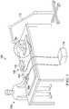
- production environment 100 has structure 102.
- Structure 102 may be comprised of a number of different materials. These materials may include, for example, without limitation, plastic, metal, composite material, ceramics, and other suitable types of materials. As depicted, structure 102 may be a composite panel.
- FIG. 1 This illustration of production environment 100 is provided for purposes of illustrating one environment in which the different illustrative embodiments may be implemented.
- the illustration of production environment 100 in Figure 1 is not meant to imply architectural limitations as to the manner in which different illustrative embodiments may be implemented.
- structure 102 need not be a composite panel.
- structure 102 may be a metallic panel.
- structure 102 may be a composite stiffener.
- structure 102 may be a fuselage section of an aircraft.
- structure 102 need not be supported by a table as depicted.
- Production environment 200 may be one implementation of production environment 100 of Figure 1 .
- Production environment 200 comprises controller 204 , inspection equipment 206 , and structure 208.
- Controller 204 may be configured to control inspection of structure 208 by inspection equipment 206 using number of parameters 210.
- Number of parameters 210 may comprise at least one of amplitude, number of pulses, incidence angle, or other suitable parameters.
- the phrase "at least one of,” when used with a list of items, means different combinations of one or more of the listed items may be used, and only one of each item in the list may be needed.
- “at least one of item A, item B, and item C" may include, without limitation, item A, item A and item B, or item B. This example also may include item A, item B, and item C or item B and item C.
- "at least one of' may be, for example, without limitation, two of item A, one of item B, and ten of item C; four of item B and seven of item C; and other suitable combinations.
- the item may be a particular object, thing, or a category. In other words, at least one of means any combination of items and number of items may be used from the list but not all of the items in the list are required.
- Inspection equipment 206 is configured to inspect structure 208.
- Structure 208 comprises material 212 , number of inconsistencies 214 , and thickness 216.
- Material 212 has material velocity 218.
- Material velocity 218 is a measure of the speed at which signals propagate in material 212.
- Inspection equipment 206 may identify number of inconsistencies 214 through inspection of structure 208.
- a "number of' items means one or more items.
- number of inconsistencies 214 means one or more inconsistencies.
- Number of inconsistencies 214 comprises a number of undesirable conditions within structure 208.
- Number of inconsistencies 214 may include foreign material, debris, voids, or other suitable undesirable conditions.
- Coupling material 222 may be used to increase the transmission of number of signals 219 into structure 208.
- Coupling material 222 has thickness 224 and material velocity 226.
- Material velocity 226 is a measure of the speed at which signals propagate in coupling material 222.
- material velocity 226 may be different than material velocity 218.
- the difference between material velocity 226 and material velocity 218 is smaller than the difference between the velocity of air and material velocity 218. Accordingly, coupling material 222 reduces the reflection which would occur if air were between transducer array 220 and structure 208.
- Coupling material 222 may be one of an oil, a gel, a hydrogel, water, or other suitable materials. Coupling material 222 may be selected based on material velocity 218, material velocity 226 , inactivity with material 212 , cost, or other suitable parameters.
- Inspection equipment 206 may inspect structure 208 by sending number of signals 219 into structure 208 using transducer array 220.
- Transducer array 220 is held within cover 225 and comprises plurality of elements 228.
- Plurality of elements 228 comprises number of sending elements 230, number of inactive elements 232 , and number of receiving elements 234.
- Controller 204 may configure inspection equipment 206 by configuring each of plurality of elements 228 of transducer array 220 to be one of number of sending elements 230, number of inactive elements 232 , or number of receiving elements 234.
- Controller 204 may configure plurality of elements 228 based on at least one of incidence angle 223 of number of signals 219 to be sent, thickness 216 , material velocity 218 of material 212 , thickness 224 of coupling material 222 , material velocity 226 of coupling material 222 , or any other suitable parameter.
- controller 204 may configure transducer array 220 based on second location 238 and first location 236.
- Number of sending elements 230 is configured to send number of signals 219 into structure 208.
- transducer array 220 may send number of signals 219 at incidence angle 223.
- Incidence angle 223 may be any desirable angle as long as response signal 242 reflected from back surface of structure 208 would reach transducer array 220. In one illustrative example, incidence angle 223 may be 6 degrees.
- number of sending elements 230 may send number of signals 219 at incidence angle 223 using electronic time-delay beam steering or other suitable methods. By sending number of signals 219 from transducer array 220 at incidence angle 223 using electronic time-delay beam steering, transducer array 220 may remain parallel to structure 208.
- Number of inactive elements 232 are not configured to send or receive signals. As a result, responses reaching number of inactive elements 232 will not be detected. By not detecting response signal 240 reflected from number of inconsistencies 214 , ultrasound inspection may be improved.
- number of inactive elements 232 may be located at second location 238. In some illustrative examples, only some inactive elements of number of inactive elements 232 may be located at second location 238. In some illustrative examples, second location 238 of transducer array 220 may be identified based on at least one of incidence angle 223 , thickness 224 , thickness 216 , material velocity 226 , and material velocity 218. In some illustrative examples, second location 238 may be an estimated receiving location for response signal 240 reflected from an inconsistency of number of inconsistencies 214 within structure 208. In some illustrative examples, second location 238 may be determined based on processing characteristics 239 of structure 208. Examples of processing characteristics 239 may be likely chemical composition of number of inconsistencies 214 during processing of structure 208 , layers of structure 208 most susceptible to inconsistencies during processing of structure 208 , and other suitable processing characteristics.
- Number of inactive elements 232 may increase sensitivity of ultrasound inspection for detecting inconsistencies 214. If response signal 240 reaches number of inactive elements 232 , response signal 240 will not be detected. By not detecting response signal 240 reflected from number of inconsistencies 214 , ultrasound inspection may be improved.
- Ultrasound inspection may be improved by decreasing the amplitude of response signal 242 relative to number of inconsistencies 214.
- amplitude of response signal 242 will be greater when an inconsistency in number of inconsistencies 214 is not present in the tested area of structure 208.
- the amplitude of response signal 242 will be smaller when an inconsistency in number of inconsistencies 214 is present in the tested area of structure 208.
- number of inactive elements 232 is configured to decrease an amplitude of response signal 242 reflected from the back surface of structure 208 when an inconsistency in number of inconsistencies 214 is present.
- incidence angle 223 is configured to decrease an amplitude of response signal 242 reflected from the back surface of structure 208 when an inconsistency is present.
- An inconsistency in number of inconsistencies 214 may be identified by subtracting amplitude of response signal 242 from a desired value.
- the desired value may be the amplitude of a response signal reflected from the back wall of structure 208 when an inconsistency in number of inconsistencies 214 is not present.
- the difference in amplitude may be greater. Further, by not detecting response signal 240 reflected from number of inconsistencies 214 , the difference in amplitude may be more easily identified. Further, by not detecting response signal 240 reflected from number of inconsistencies 214 , the difference in amplitude may be identified more quickly.
- the sensitivity of ultrasound inspection to number of inconsistencies 214 may be increased.
- inspection times may be reduced.
- increasing sensitivity may allow for more complex structures to be inspected.
- second location 238 may be determined based on first location 236. In these illustrative examples, second location 238 may be the area of transducer array 220 between number of sending elements 230 and first location 236.
- the difference between the time response signal 240 is received and the time response signal 242 is received is also increased when compared to sending number of signals 219 in a direction normal to structure 208.
- This increase in time difference may also increase one of sensitivity and the signal to noise ratio.
- transducer array 220 may not have second location 238.
- Number of inactive elements 232 may be located in transducer array 220 based on not being one of number of sending elements 230 or number of receiving elements 234.
- articulated arm 110 holds inspection equipment 104.
- Articulated arm 110 may move inspection equipment 104 across structure 102.
- Inspection equipment 104 has cover 302. Cover 302 may be pressed against structure 102 as inspection equipment 104 is moved across structure 102.
- Inspection equipment 104 is configured to identify inconsistency 412 in structure 102.
- Inspection equipment 104 has cover 302 and transducer array 402.
- Transducer array 402 has plurality of elements 404.
- Transducer array 402 is configured to send signals into structure 102.
- Structure 102 has front surface 403 , back surface 405 , plurality of layers of material 406 , and inconsistency 412.
- Transducer array 402 may send signals through coupling material 408 and front surface 403 into structure 102.
- coupling material 408 may comprise water.
- inactive elements 418 are located at second location 424 of transducer array 402.
- Receiving elements 420 are located at first location 426.
- sending elements 416 may send signal 428 at an incident angle through coupling material 408 and into structure 102. As depicted, some of signal 428 will reflect off inconsistency 412 as response signal 430. As depicted, response signal 430 will reach transducer array 402 at inactive elements 418. Accordingly, response signal 430 will not be detected by transducer array 402.
- the remainder of signal 428 may continue to back surface 405 of structure 102.
- the remainder of signal 428 may reflect off back surface 405 as response signal 432.
- response signal 432 will reach transducer array 402 at receiving elements 420. Accordingly, response signal 432 will be detected by transducer array 402.
- the sensitivity of the inspection by transducer array 402 may be greater than an inspection using signals normal to structure 102. Increased sensitivity may result in faster evaluation times. Further, increased sensitivity may allow transducer array 402 to inspect more complex structures than could be inspected using signals normal to the structure. Yet further, by not detecting response signal 430 , the signal to noise ratio of the inspection by transducer array 402 may be greater than by using signals normal to structure 102.
- Figure 1 and Figures 3 -4 illustrations of an inspection system are depicted in accordance with an illustrative embodiment.
- the different components shown in Figure 1 and Figures 3 -4 for inspection equipment 104 may be combined with components in Figure 2 , used with components in Figure 2 , or a combination of the two. Additionally, some of the components in these figures may be illustrative examples of how components shown in block form in Figure 2 may be implemented as physical structures.
- Testing environment 500 comprises transducer array 502 , coupling material 504 , and structure 506.
- Structure 506 has front surface 508 and back surface 518.
- coupling material 504 has thickness 510 and material velocity 512.
- structure 506 has thickness 514 and material velocity 516.
- a calculation may be based on signals being sent from third location 520.
- Signal 521 may be sent at incidence angle 522.
- Signal 521 may travel distance 524 prior to reaching front surface 508.
- angle 521 may change from incidence angle 522 to angle 526.
- the angle of signal 521 may change at front surface 508 as a result of the difference in value between material velocity 512 and material velocity 516.
- Signal 521 may travel distance 528 as signal 521 travels from front surface 508 to back surface 518.
- signal 521 may reflect off back surface 518.
- Signal response 529 produced may be substantially the same angle as angle 526.
- Signal response 529 may then travel through structure 506 towards front surface 508.
- the angle of signal response 529 may change.
- the angle of signal response 529 may change at front surface 508 as a result of the difference in value between material velocity 512 and material velocity 516.
- the angle of signal response 529 may be substantially the same angle as incidence angle 522.
- Signal response 529 may then travel through coupling material 504 towards transducer array 502. Signal response 529 may then reach structure 506 at first location 532.
- First location 532 may be described as an estimated receiving location for a response reflected from back surface 518 of structure 506.
- Distance 530 comprises a total traversed distance from third location 520 to first location 532.
- Distance 530 may be determined by any suitable method.
- Distance 530 may be expressed as twice the sum of distance 524 and distance 528.
- Distance 530 and third location 520 may be used to identify first location 532.
- FIG. 6 an illustration of a process for inspecting a structure is depicted in accordance with an illustrative embodiment.
- the process illustrated in Figure 5 may be implemented using inspection equipment 206 of Figure 2 . Further, this process may be implemented to inspect structure 208 for number of inconsistencies 214 in Figure 2 .
- the process may begin by sending a signal into a structure at an incidence angle from a transducer array (operation 600 ).
- the signal may be directed at an incidence angle by electronic time-delay beam steering.
- the process may then detect a response signal at the transducer array to form a received response, the response signal reflected from the structure in response to the signal sent into the structure (operation 602 ). Afterwards the process terminates.
- Data processing system 700 may be one implementation of controller 204 of Figure 2 .
- Data processing system 700 may be used to implement identification of at least one of number of sending elements 230 , number of inactive elements 232 , and number of receiving elements 234 of Figure 2 .
- data processing system 700 may be used to control sending signals by transducer array 220 of Figure 2 .
- data processing system 700 includes communications framework 702 , which provides communications between processor unit 704 , memory 706 , persistent storage 708 , communications unit 710 , input/output (I/O) unit 712 , and display 714.
- communications framework 702 may take the form of a bus system.
- Processor unit 704 serves to execute instructions for software that may be loaded into memory 706.
- Processor unit 704 may be a number of processors, a multi-processor core, or some other type of processor, depending on the particular implementation.
- Memory 706 and persistent storage 708 are examples of storage devices 716.
- a storage device is any piece of hardware that is capable of storing information, such as, for example, without limitation, data, program code in functional form, and/or other suitable information either on a temporary basis and/or a permanent basis.
- Storage devices 716 may also be referred to as computer readable storage devices in these illustrative examples.
- Memory 706 in these examples, may be, for example, a random access memory or any other suitable volatile or non-volatile storage device.
- Persistent storage 708 may take various forms, depending on the particular implementation.
- persistent storage 708 may contain one or more components or devices.
- persistent storage 708 may be a hard drive, a flash memory, a rewritable optical disk, a rewritable magnetic tape, or some combination of the above.
- the media used by persistent storage 708 also may be removable.
- a removable hard drive may be used for persistent storage 708.
- Communications unit 710 in these illustrative examples, provides for communications with other data processing systems or devices.
- communications unit 710 is a network interface card.
- Input/output unit 712 allows for input and output of data with other devices that may be connected to data processing system 700.
- input/output unit 712 may provide a connection for user input through a keyboard, a mouse, and/or some other suitable input device. Further, input/output unit 712 may send output to a printer.
- Display 714 provides a mechanism to display information to a user.
- Instructions for the operating system, applications, and/or programs may be located in storage devices 716 , which are in communication with processor unit 704 through communications framework 702.
- the processes of the different embodiments may be performed by processor unit 704 using computer-implemented instructions, which may be located in a memory, such as memory 706.
- program code computer usable program code
- computer readable program code that may be read and executed by a processor in processor unit 704.
- the program code in the different embodiments may be embodied on different physical or computer readable storage media, such as memory 706 or persistent storage 708.
- Program code 718 is located in a functional form on computer readable media 720 that is selectively removable and may be loaded onto or transferred to data processing system 700 for execution by processor unit 704.
- Program code 718 and computer readable media 720 form computer program product 722 in these illustrative examples.
- computer readable media 720 may be computer readable storage media 724 or computer readable signal media 726.
- computer readable storage media 724 is a physical or tangible storage device used to store program code 718 rather than a medium that propagates or transmits program code 718.
- program code 718 may be transferred to data processing system 700 using computer readable signal media 726.
- Computer readable signal media 726 may be, for example, a propagated data signal containing program code 718.
- Computer readable signal media 726 may be an electromagnetic signal, an optical signal, and/or any other suitable type of signal. These signals may be transmitted over communications links, such as wireless communications links, optical fiber cable, coaxial cable, a wire, and/or any other suitable type of communications link.
- the different components illustrated for data processing system 700 are not meant to provide architectural limitations to the manner in which different embodiments may be implemented.
- the different illustrative embodiments may be implemented in a data processing system including components in addition to and/or in place of those illustrated for data processing system 700.
- Other components shown in Figure 7 can be varied from the illustrative examples shown.
- the different embodiments may be implemented using any hardware device or system capable of running program code 718.
- aircraft manufacturing and service method 800 may be described in the context of aircraft manufacturing and service method 800 as shown in Figure 8 and aircraft 900 as shown in Figure 9 .
- Figure 8 an illustration of an aircraft manufacturing and service method is depicted in the form of a block diagram in accordance with an illustrative embodiment.
- aircraft manufacturing and service method 800 may include specification and design 802 of aircraft 900 in Figure 9 and material procurement 804.
- aircraft 900 is produced by aircraft manufacturing and service method 800 in Figure 8 and may include airframe 902 with plurality of systems 904 and interior 906.
- systems 904 include one or more of propulsion system 908 , electrical system 910 , hydraulic system 912 , and environmental system 914. Any number of other systems may be included.
- propulsion system 908 electrical system 910
- hydraulic system 912 hydraulic system 912
- environmental system 914 any number of other systems may be included.
- an aerospace example is shown, different illustrative embodiments may be applied to other industries, such as the automotive industry.
- Apparatuses and methods embodied herein may be employed during at least one of the stages of aircraft manufacturing and service method 800 in Figure 8 .
- One or more illustrative embodiments may be used during component and subassembly manufacturing 806.
- inspection equipment 206 in Figure 2 may be used during component and subassembly manufacturing 806.
- inspection equipment 206 may also be used to perform replacements during maintenance and service 814.
- replacement parts for aircraft 900 may be inspected during scheduled maintenance for aircraft 900.
- the different illustrative embodiments provide a method and apparatus for sending signals from a transducer array at incidence angles.
- signals may be sent from a transducer array at an incidence angle using electronic time-delay beam steering.
- a number of inactive elements may receive response signals reflected from a number of inconsistencies in a structure.
- the different illustrative embodiments may provide a method and apparatus for inspecting a structure in reduced time.
- the different illustrative embodiments may provide a method and apparatus for inspecting a structure with greater sensitivity to debris or other foreign materials.
- the different illustrative embodiments may provide a method and apparatus for providing a greater signal to noise ratio in ultrasound inspection using a transducer array.
Claims (10)
- Verfahren, das aufweist:Senden (600) eines Ultraschallsignals unter einem Einfallswinkel (223) von einer Ultraschallwandleranordnung (220) in eine Struktur (208);Ermitteln (602) eines Antwortsignals (242) an der Ultraschallwandleranordnung (220), um eine empfangene Antwort zu bilden, wobei das Antwortsignal (242) von der Struktur (208) im Ansprechen auf das in die Struktur (208) gesendete Ultraschallsignal reflektiert wird;Identifizieren einer ersten Stelle (236) der Ultraschallwandleranordnung (220), wobei die erste Stelle (236) eine geschätzte Empfangsstelle für ein Antwortsignal (242) ist, das von einer Rückfläche der Struktur (208) reflektiert wird;Ermitteln einer zweiten Stelle (238) der Ultraschallwandleranordnung (220), wobei die zweite Stelle (238) eine geschätzte Empfangsstelle für ein Antwortsignal (240) ist, das von einer Inkonsistenz innerhalb der Struktur (208) reflektiert wird;Konfigurieren der Ultraschallwandleranordnung (220) derart, dass inaktive Elemente (232) an der zweiten Stelle (238) angeordnet sind; undKonfigurieren der Anzahl inaktiver Elemente (232), um eine Amplitude des Antwortsignals (242), das von der Rückfläche der Struktur (208) reflektiert wird, zu verringern, wenn die Inkonsistenz vorhanden ist.
- Verfahren nach Anspruch 1, das des Weiteren aufweist:
Konfigurieren der Ultraschallwandleranordnung (220) derart, dass Empfangselemente (234) an der ersten Stelle (236) angeordnet sind. - Verfahren nach Anspruch 1, das des Weiteren aufweist:
Identifizieren einer Inkonsistenz innerhalb der Struktur (208) unter Verwendung des Antwortsignals (242). - Verfahren nach Anspruch 3, wobei die Inkonsistenz Fremdmaterial (208) innerhalb der Struktur aufweist.
- Verfahren nach Anspruch 1, wobei die Struktur (208) ein Verbundmaterial aufweist.
- Verfahren nach Anspruch 1, wobei die Struktur (280) aus einem Material besteht, das ausgewählt wird aus wenigstens einem von einem Metall, einem Verbundmaterial, einem Kunststoff und einem keramischen Material.
- Verfahren nach Anspruch 1, wobei die Struktur (280) aus einer Vielzahl von Materialschichten (406) besteht.
- Verfahren nach Anspruch 1, wobei das Senden des Ultraschallsignals unter dem Einfallswinkel (223) von der Ultraschallwandleranordnung (220) in die Struktur (208) das Senden des Ultraschallsignals unter dem Einfallswinkel (223) von der Ultraschallwandleranordnung (200) in die Struktur (208) unter Verwendung von elektronischer Zeitverzögerungs-Lichtablenkung aufweist.
- Vorrichtung, die aufweist:eine Ultraschallwandleranordnung (220), die eine Vielzahl von Elementen (228) aufweist;eine Anzahl von Sendeelementen (230) in der Vielzahl von Elementen (228), die dazu konfiguriert sind, ein Ultraschallsignal unter einem Einfallswinkel (223) in eine Struktur (208) zu senden; undeine Anzahl von Empfangselementen (234) in der Vielzahl von Elementen (228), die dazu konfiguriert sind, ein Antwortsignal (242) zu ermitteln, das von einer Rückfläche der Struktur (208) reflektiert wird,wobei die Anzahl von Empfangselementen (234) an einer ersten Stelle (236) angeordnet sind, wobei die erste Stelle (236) eine geschätzte Empfangsstelle für das Antwortsignal (242) ist, das von der Rückfläche der Struktur (208) reflektiert wird; weiterhin aufweisend:eine Anzahl inaktiver Elemente (232) in der Vielzahl von Elementen (228), die zwischen der Anzahl von Sendeelementen (230) und der Anzahl von Empfangselementen (234) angeordnet sind,wobei die Anzahl inaktiver Elemente (232) an einer zweiten Stelle (238) angeordnet sind, wobei die zweite Stelle (238) eine geschätzte Empfangsstelle für ein Antwortsignal (240) ist, das von einer Inkonsistenz innerhalb der Struktur (208) reflektiert wird, undwobei die Anzahl inaktiver Elemente (232) dazu konfiguriert ist, eine Amplitude des Antwortsignals (242), das von der Rückfläche der Struktur (208) reflektiert wird, zu verringern, wenn die Inkonsistenz vorhanden ist; und weiterhin aufweisend:einen Controller (204), der dazu ausgelegt ist, jedes der Vielzahl von Elementen (228) der Wandleranordnung (220) zu konfigurieren, um eines der Anzahl von Sendeelementen (230), der Anzahl inaktiver Elemente (232) oder der Anzahl von Empfangselementen (234) zu sein.
- Vorrichtung nach Anspruch 9, wobei der Einfallswinkel dazu konfiguriert ist, eine Amplitude des Antwortsignals (242), das von der Rückfläche der Struktur (208) reflektiert wird, zu verringern, wenn eine Inkonsistenz vorhanden ist.
Applications Claiming Priority (2)
| Application Number | Priority Date | Filing Date | Title |
|---|---|---|---|
| US13/860,687 US9304114B2 (en) | 2013-04-11 | 2013-04-11 | Ultrasonic inspection using incidence angles |
| PCT/US2014/028510 WO2014168729A2 (en) | 2013-04-11 | 2014-03-14 | Ultrasonic inspection using incidence angles |
Publications (2)
| Publication Number | Publication Date |
|---|---|
| EP2984479A2 EP2984479A2 (de) | 2016-02-17 |
| EP2984479B1 true EP2984479B1 (de) | 2020-10-28 |
Family
ID=50487191
Family Applications (1)
| Application Number | Title | Priority Date | Filing Date |
|---|---|---|---|
| EP14717620.0A Active EP2984479B1 (de) | 2013-04-11 | 2014-03-14 | Ultraschallprüfung unter verwendung von einfallswinkeln |
Country Status (6)
| Country | Link |
|---|---|
| US (1) | US9304114B2 (de) |
| EP (1) | EP2984479B1 (de) |
| JP (1) | JP6367921B2 (de) |
| KR (1) | KR102265061B1 (de) |
| ES (1) | ES2846753T3 (de) |
| WO (1) | WO2014168729A2 (de) |
Families Citing this family (4)
| Publication number | Priority date | Publication date | Assignee | Title |
|---|---|---|---|---|
| US9778231B2 (en) * | 2015-05-13 | 2017-10-03 | Spirit Aerosystems, Inc. | Ultrasonic inspection end effector |
| US10197392B2 (en) | 2015-06-23 | 2019-02-05 | The Boeing Company | Automated resin ridge reduction system |
| US10571385B2 (en) | 2017-11-22 | 2020-02-25 | The Boeing Company | Ultrasonic inspection of a structure with a ramp |
| US10816512B2 (en) * | 2018-03-29 | 2020-10-27 | The Boeing Company | Inspection of a structure with a sloped back wall |
Citations (3)
| Publication number | Priority date | Publication date | Assignee | Title |
|---|---|---|---|---|
| EP2124045A1 (de) * | 2007-02-28 | 2009-11-25 | JFE Steel Corporation | Ultraschalltestvorrichtung für röhrenförmiges objekt und ultraschalltestverfahren |
| EP2124046A1 (de) * | 2007-02-28 | 2009-11-25 | JFE Steel Corporation | Verfahren zur qualitätsregelung eines röhrenförmigen körpers und verfahren zur herstellung eines röhrenförmigen körpers |
| EP2182352A2 (de) * | 2008-10-29 | 2010-05-05 | Hitachi Ltd. | Apparatus and method for ultrasonic testing |
Family Cites Families (13)
| Publication number | Priority date | Publication date | Assignee | Title |
|---|---|---|---|---|
| JPH05312792A (ja) * | 1992-05-12 | 1993-11-22 | Hitachi Ltd | アレイ探触子による割れ検出法 |
| JP2838045B2 (ja) * | 1994-09-09 | 1998-12-16 | 日本クラウトクレーマー株式会社 | 超音波を用いた被検材の内部検査法及びその装置 |
| JPH11183446A (ja) | 1997-12-25 | 1999-07-09 | Nkk Corp | 溶接部の超音波探傷方法および装置 |
| US6813950B2 (en) * | 2002-07-25 | 2004-11-09 | R/D Tech Inc. | Phased array ultrasonic NDT system for tubes and pipes |
| US6789427B2 (en) * | 2002-09-16 | 2004-09-14 | General Electric Company | Phased array ultrasonic inspection method for industrial applications |
| US7293461B1 (en) * | 2003-10-22 | 2007-11-13 | Richard Girndt | Ultrasonic tubulars inspection device |
| JP2007322350A (ja) | 2006-06-05 | 2007-12-13 | Tokyo Electric Power Co Inc:The | 超音波探傷装置及び方法 |
| US7823451B2 (en) * | 2008-05-06 | 2010-11-02 | The Boeing Company | Pulse echo/through transmission ultrasonic testing |
| US8192075B2 (en) * | 2008-08-19 | 2012-06-05 | Ge Inspection Technologies, Lp | Method for performing ultrasonic testing |
| DE102008041835A1 (de) | 2008-09-05 | 2010-03-18 | Ge Inspection Technologies Gmbh | Impulsechoverfahren mittels Gruppenstrahler und Temperaturkompensation |
| US8577629B2 (en) * | 2009-03-25 | 2013-11-05 | Olympus Ndt | Method and system for transducer element fault detection for phased array ultrasonic instruments |
| JP5421633B2 (ja) * | 2009-03-30 | 2014-02-19 | 中央精機株式会社 | 超音波探査方法および超音波探査装置 |
| JP5253424B2 (ja) * | 2010-01-05 | 2013-07-31 | 日立Geニュークリア・エナジー株式会社 | 超音波探傷方法及び超音波探傷装置 |
-
2013
- 2013-04-11 US US13/860,687 patent/US9304114B2/en active Active
-
2014
- 2014-03-14 ES ES14717620T patent/ES2846753T3/es active Active
- 2014-03-14 KR KR1020157023016A patent/KR102265061B1/ko active IP Right Grant
- 2014-03-14 JP JP2016507545A patent/JP6367921B2/ja active Active
- 2014-03-14 EP EP14717620.0A patent/EP2984479B1/de active Active
- 2014-03-14 WO PCT/US2014/028510 patent/WO2014168729A2/en active Application Filing
Patent Citations (3)
| Publication number | Priority date | Publication date | Assignee | Title |
|---|---|---|---|---|
| EP2124045A1 (de) * | 2007-02-28 | 2009-11-25 | JFE Steel Corporation | Ultraschalltestvorrichtung für röhrenförmiges objekt und ultraschalltestverfahren |
| EP2124046A1 (de) * | 2007-02-28 | 2009-11-25 | JFE Steel Corporation | Verfahren zur qualitätsregelung eines röhrenförmigen körpers und verfahren zur herstellung eines röhrenförmigen körpers |
| EP2182352A2 (de) * | 2008-10-29 | 2010-05-05 | Hitachi Ltd. | Apparatus and method for ultrasonic testing |
Also Published As
| Publication number | Publication date |
|---|---|
| WO2014168729A3 (en) | 2014-12-24 |
| JP2016514848A (ja) | 2016-05-23 |
| US9304114B2 (en) | 2016-04-05 |
| EP2984479A2 (de) | 2016-02-17 |
| US20140305220A1 (en) | 2014-10-16 |
| WO2014168729A2 (en) | 2014-10-16 |
| KR20160023634A (ko) | 2016-03-03 |
| ES2846753T3 (es) | 2021-07-29 |
| JP6367921B2 (ja) | 2018-08-01 |
| KR102265061B1 (ko) | 2021-06-15 |
Similar Documents
| Publication | Publication Date | Title |
|---|---|---|
| Ricci et al. | Guided waves for structural health monitoring in composites: A review and implementation strategies | |
| Memmolo et al. | Guided wave propagation and scattering for structural health monitoring of stiffened composites | |
| CN107132277B (zh) | 结构的检查 | |
| EP2126559B1 (de) | Verfahren und vorrichtung zur inspektion eines werkstücks mit winkelversetzten ultraschallsignalen | |
| US7367236B2 (en) | Non-destructive inspection system and associated method | |
| US7712369B2 (en) | Array-based system and method for inspecting a workpiece with backscattered ultrasonic signals | |
| US10444195B2 (en) | Detection of near surface inconsistencies in structures | |
| Tan et al. | Comparison of Lamb waves and pulse echo in detection of near-surface defects in laminate plates | |
| Ramadas et al. | Lamb wave based ultrasonic imaging of interface delamination in a composite T-joint | |
| US8694269B2 (en) | Reducing the ringing of actuator elements in ultrasound based health monitoring systems | |
| US8707787B1 (en) | Time delay based health monitoring system using a sensor network | |
| US10126122B2 (en) | Ultrasonic inspection of wrinkles in composite objects | |
| Geetha et al. | Laser Doppler imaging of delamination in a composite T-joint with remotely located ultrasonic actuators | |
| EP2984479B1 (de) | Ultraschallprüfung unter verwendung von einfallswinkeln | |
| EP2602615A2 (de) | Referenzfreies Inkonsistenzdetektionssystem | |
| CA3171871A1 (en) | System and method for portable ultrasonic testing | |
| Cawley | Guided waves in long range nondestructive testing and structural health monitoring: Principles, history of applications and prospects | |
| Djordjevic | Ultrasonic characterization of advanced composite materials | |
| Fromme | Guided wave testing | |
| Vyas et al. | A review on nondestructive techniques and characteristics of composite materials for the aerospace system | |
| Zhong et al. | Ultrasonic Testing Techniques for Nondestructive Evaluation of Fiber-Reinforced Composite Structures | |
| Djordjevic | Ultrasonic Nondestructive Testing of Large-scale Composites | |
| Liu | Study on Damage Identification Approaches for Ultrasonic Lamb Wave-based Structural Health Monitoring and Off-line Non-destructive Evaluation | |
| Szewieczek et al. | Ultrasonic impact detection techniques for an EC135 tailboom |
Legal Events
| Date | Code | Title | Description |
|---|---|---|---|
| PUAI | Public reference made under article 153(3) epc to a published international application that has entered the european phase |
Free format text: ORIGINAL CODE: 0009012 |
|
| 17P | Request for examination filed |
Effective date: 20151105 |
|
| AK | Designated contracting states |
Kind code of ref document: A2 Designated state(s): AL AT BE BG CH CY CZ DE DK EE ES FI FR GB GR HR HU IE IS IT LI LT LU LV MC MK MT NL NO PL PT RO RS SE SI SK SM TR |
|
| AX | Request for extension of the european patent |
Extension state: BA ME |
|
| DAX | Request for extension of the european patent (deleted) | ||
| STAA | Information on the status of an ep patent application or granted ep patent |
Free format text: STATUS: EXAMINATION IS IN PROGRESS |
|
| PUAG | Search results despatched under rule 164(2) epc together with communication from examining division |
Free format text: ORIGINAL CODE: 0009017 |
|
| 17Q | First examination report despatched |
Effective date: 20190807 |
|
| B565 | Issuance of search results under rule 164(2) epc |
Effective date: 20190807 |
|
| RIC1 | Information provided on ipc code assigned before grant |
Ipc: G01N 29/26 20060101AFI20190802BHEP Ipc: G10K 11/34 20060101ALI20190802BHEP Ipc: G01N 29/04 20060101ALI20190802BHEP |
|
| GRAP | Despatch of communication of intention to grant a patent |
Free format text: ORIGINAL CODE: EPIDOSNIGR1 |
|
| STAA | Information on the status of an ep patent application or granted ep patent |
Free format text: STATUS: GRANT OF PATENT IS INTENDED |
|
| RIC1 | Information provided on ipc code assigned before grant |
Ipc: G10K 11/34 20060101ALI20200512BHEP Ipc: G01N 29/26 20060101AFI20200512BHEP Ipc: G01N 29/04 20060101ALI20200512BHEP |
|
| INTG | Intention to grant announced |
Effective date: 20200605 |
|
| GRAS | Grant fee paid |
Free format text: ORIGINAL CODE: EPIDOSNIGR3 |
|
| GRAA | (expected) grant |
Free format text: ORIGINAL CODE: 0009210 |
|
| STAA | Information on the status of an ep patent application or granted ep patent |
Free format text: STATUS: THE PATENT HAS BEEN GRANTED |
|
| AK | Designated contracting states |
Kind code of ref document: B1 Designated state(s): AL AT BE BG CH CY CZ DE DK EE ES FI FR GB GR HR HU IE IS IT LI LT LU LV MC MK MT NL NO PL PT RO RS SE SI SK SM TR |
|
| REG | Reference to a national code |
Ref country code: GB Ref legal event code: FG4D |
|
| REG | Reference to a national code |
Ref country code: CH Ref legal event code: EP |
|
| REG | Reference to a national code |
Ref country code: DE Ref legal event code: R096 Ref document number: 602014071668 Country of ref document: DE |
|
| REG | Reference to a national code |
Ref country code: AT Ref legal event code: REF Ref document number: 1328715 Country of ref document: AT Kind code of ref document: T Effective date: 20201115 |
|
| REG | Reference to a national code |
Ref country code: IE Ref legal event code: FG4D |
|
| REG | Reference to a national code |
Ref country code: AT Ref legal event code: MK05 Ref document number: 1328715 Country of ref document: AT Kind code of ref document: T Effective date: 20201028 |
|
| REG | Reference to a national code |
Ref country code: NL Ref legal event code: MP Effective date: 20201028 |
|
| PG25 | Lapsed in a contracting state [announced via postgrant information from national office to epo] |
Ref country code: PT Free format text: LAPSE BECAUSE OF FAILURE TO SUBMIT A TRANSLATION OF THE DESCRIPTION OR TO PAY THE FEE WITHIN THE PRESCRIBED TIME-LIMIT Effective date: 20210301 Ref country code: NL Free format text: LAPSE BECAUSE OF FAILURE TO SUBMIT A TRANSLATION OF THE DESCRIPTION OR TO PAY THE FEE WITHIN THE PRESCRIBED TIME-LIMIT Effective date: 20201028 Ref country code: NO Free format text: LAPSE BECAUSE OF FAILURE TO SUBMIT A TRANSLATION OF THE DESCRIPTION OR TO PAY THE FEE WITHIN THE PRESCRIBED TIME-LIMIT Effective date: 20210128 Ref country code: FI Free format text: LAPSE BECAUSE OF FAILURE TO SUBMIT A TRANSLATION OF THE DESCRIPTION OR TO PAY THE FEE WITHIN THE PRESCRIBED TIME-LIMIT Effective date: 20201028 Ref country code: RS Free format text: LAPSE BECAUSE OF FAILURE TO SUBMIT A TRANSLATION OF THE DESCRIPTION OR TO PAY THE FEE WITHIN THE PRESCRIBED TIME-LIMIT Effective date: 20201028 Ref country code: GR Free format text: LAPSE BECAUSE OF FAILURE TO SUBMIT A TRANSLATION OF THE DESCRIPTION OR TO PAY THE FEE WITHIN THE PRESCRIBED TIME-LIMIT Effective date: 20210129 |
|
| REG | Reference to a national code |
Ref country code: LT Ref legal event code: MG4D |
|
| PG25 | Lapsed in a contracting state [announced via postgrant information from national office to epo] |
Ref country code: AT Free format text: LAPSE BECAUSE OF FAILURE TO SUBMIT A TRANSLATION OF THE DESCRIPTION OR TO PAY THE FEE WITHIN THE PRESCRIBED TIME-LIMIT Effective date: 20201028 Ref country code: BG Free format text: LAPSE BECAUSE OF FAILURE TO SUBMIT A TRANSLATION OF THE DESCRIPTION OR TO PAY THE FEE WITHIN THE PRESCRIBED TIME-LIMIT Effective date: 20210128 Ref country code: IS Free format text: LAPSE BECAUSE OF FAILURE TO SUBMIT A TRANSLATION OF THE DESCRIPTION OR TO PAY THE FEE WITHIN THE PRESCRIBED TIME-LIMIT Effective date: 20210228 Ref country code: PL Free format text: LAPSE BECAUSE OF FAILURE TO SUBMIT A TRANSLATION OF THE DESCRIPTION OR TO PAY THE FEE WITHIN THE PRESCRIBED TIME-LIMIT Effective date: 20201028 Ref country code: LV Free format text: LAPSE BECAUSE OF FAILURE TO SUBMIT A TRANSLATION OF THE DESCRIPTION OR TO PAY THE FEE WITHIN THE PRESCRIBED TIME-LIMIT Effective date: 20201028 Ref country code: SE Free format text: LAPSE BECAUSE OF FAILURE TO SUBMIT A TRANSLATION OF THE DESCRIPTION OR TO PAY THE FEE WITHIN THE PRESCRIBED TIME-LIMIT Effective date: 20201028 |
|
| PG25 | Lapsed in a contracting state [announced via postgrant information from national office to epo] |
Ref country code: HR Free format text: LAPSE BECAUSE OF FAILURE TO SUBMIT A TRANSLATION OF THE DESCRIPTION OR TO PAY THE FEE WITHIN THE PRESCRIBED TIME-LIMIT Effective date: 20201028 |
|
| REG | Reference to a national code |
Ref country code: DE Ref legal event code: R097 Ref document number: 602014071668 Country of ref document: DE Ref country code: ES Ref legal event code: FG2A Ref document number: 2846753 Country of ref document: ES Kind code of ref document: T3 Effective date: 20210729 |
|
| PG25 | Lapsed in a contracting state [announced via postgrant information from national office to epo] |
Ref country code: SK Free format text: LAPSE BECAUSE OF FAILURE TO SUBMIT A TRANSLATION OF THE DESCRIPTION OR TO PAY THE FEE WITHIN THE PRESCRIBED TIME-LIMIT Effective date: 20201028 Ref country code: RO Free format text: LAPSE BECAUSE OF FAILURE TO SUBMIT A TRANSLATION OF THE DESCRIPTION OR TO PAY THE FEE WITHIN THE PRESCRIBED TIME-LIMIT Effective date: 20201028 Ref country code: LT Free format text: LAPSE BECAUSE OF FAILURE TO SUBMIT A TRANSLATION OF THE DESCRIPTION OR TO PAY THE FEE WITHIN THE PRESCRIBED TIME-LIMIT Effective date: 20201028 Ref country code: SM Free format text: LAPSE BECAUSE OF FAILURE TO SUBMIT A TRANSLATION OF THE DESCRIPTION OR TO PAY THE FEE WITHIN THE PRESCRIBED TIME-LIMIT Effective date: 20201028 Ref country code: EE Free format text: LAPSE BECAUSE OF FAILURE TO SUBMIT A TRANSLATION OF THE DESCRIPTION OR TO PAY THE FEE WITHIN THE PRESCRIBED TIME-LIMIT Effective date: 20201028 Ref country code: CZ Free format text: LAPSE BECAUSE OF FAILURE TO SUBMIT A TRANSLATION OF THE DESCRIPTION OR TO PAY THE FEE WITHIN THE PRESCRIBED TIME-LIMIT Effective date: 20201028 |
|
| PG25 | Lapsed in a contracting state [announced via postgrant information from national office to epo] |
Ref country code: DK Free format text: LAPSE BECAUSE OF FAILURE TO SUBMIT A TRANSLATION OF THE DESCRIPTION OR TO PAY THE FEE WITHIN THE PRESCRIBED TIME-LIMIT Effective date: 20201028 |
|
| PLBE | No opposition filed within time limit |
Free format text: ORIGINAL CODE: 0009261 |
|
| STAA | Information on the status of an ep patent application or granted ep patent |
Free format text: STATUS: NO OPPOSITION FILED WITHIN TIME LIMIT |
|
| 26N | No opposition filed |
Effective date: 20210729 |
|
| PG25 | Lapsed in a contracting state [announced via postgrant information from national office to epo] |
Ref country code: MC Free format text: LAPSE BECAUSE OF FAILURE TO SUBMIT A TRANSLATION OF THE DESCRIPTION OR TO PAY THE FEE WITHIN THE PRESCRIBED TIME-LIMIT Effective date: 20201028 Ref country code: AL Free format text: LAPSE BECAUSE OF FAILURE TO SUBMIT A TRANSLATION OF THE DESCRIPTION OR TO PAY THE FEE WITHIN THE PRESCRIBED TIME-LIMIT Effective date: 20201028 Ref country code: IT Free format text: LAPSE BECAUSE OF FAILURE TO SUBMIT A TRANSLATION OF THE DESCRIPTION OR TO PAY THE FEE WITHIN THE PRESCRIBED TIME-LIMIT Effective date: 20201028 |
|
| REG | Reference to a national code |
Ref country code: CH Ref legal event code: PL |
|
| PG25 | Lapsed in a contracting state [announced via postgrant information from national office to epo] |
Ref country code: SI Free format text: LAPSE BECAUSE OF FAILURE TO SUBMIT A TRANSLATION OF THE DESCRIPTION OR TO PAY THE FEE WITHIN THE PRESCRIBED TIME-LIMIT Effective date: 20201028 |
|
| REG | Reference to a national code |
Ref country code: BE Ref legal event code: MM Effective date: 20210331 |
|
| PG25 | Lapsed in a contracting state [announced via postgrant information from national office to epo] |
Ref country code: IE Free format text: LAPSE BECAUSE OF NON-PAYMENT OF DUE FEES Effective date: 20210314 Ref country code: LI Free format text: LAPSE BECAUSE OF NON-PAYMENT OF DUE FEES Effective date: 20210331 Ref country code: LU Free format text: LAPSE BECAUSE OF NON-PAYMENT OF DUE FEES Effective date: 20210314 Ref country code: CH Free format text: LAPSE BECAUSE OF NON-PAYMENT OF DUE FEES Effective date: 20210331 |
|
| PG25 | Lapsed in a contracting state [announced via postgrant information from national office to epo] |
Ref country code: IS Free format text: LAPSE BECAUSE OF FAILURE TO SUBMIT A TRANSLATION OF THE DESCRIPTION OR TO PAY THE FEE WITHIN THE PRESCRIBED TIME-LIMIT Effective date: 20210228 |
|
| PG25 | Lapsed in a contracting state [announced via postgrant information from national office to epo] |
Ref country code: BE Free format text: LAPSE BECAUSE OF NON-PAYMENT OF DUE FEES Effective date: 20210331 |
|
| PGFP | Annual fee paid to national office [announced via postgrant information from national office to epo] |
Ref country code: FR Payment date: 20230327 Year of fee payment: 10 |
|
| PG25 | Lapsed in a contracting state [announced via postgrant information from national office to epo] |
Ref country code: HU Free format text: LAPSE BECAUSE OF FAILURE TO SUBMIT A TRANSLATION OF THE DESCRIPTION OR TO PAY THE FEE WITHIN THE PRESCRIBED TIME-LIMIT; INVALID AB INITIO Effective date: 20140314 |
|
| PGFP | Annual fee paid to national office [announced via postgrant information from national office to epo] |
Ref country code: GB Payment date: 20230327 Year of fee payment: 10 Ref country code: DE Payment date: 20230329 Year of fee payment: 10 |
|
| P01 | Opt-out of the competence of the unified patent court (upc) registered |
Effective date: 20230516 |
|
| PG25 | Lapsed in a contracting state [announced via postgrant information from national office to epo] |
Ref country code: CY Free format text: LAPSE BECAUSE OF FAILURE TO SUBMIT A TRANSLATION OF THE DESCRIPTION OR TO PAY THE FEE WITHIN THE PRESCRIBED TIME-LIMIT Effective date: 20201028 |
|
| PGFP | Annual fee paid to national office [announced via postgrant information from national office to epo] |
Ref country code: ES Payment date: 20230403 Year of fee payment: 10 |
|
| PG25 | Lapsed in a contracting state [announced via postgrant information from national office to epo] |
Ref country code: MK Free format text: LAPSE BECAUSE OF FAILURE TO SUBMIT A TRANSLATION OF THE DESCRIPTION OR TO PAY THE FEE WITHIN THE PRESCRIBED TIME-LIMIT Effective date: 20201028 |
|
| PGFP | Annual fee paid to national office [announced via postgrant information from national office to epo] |
Ref country code: DE Payment date: 20240327 Year of fee payment: 11 Ref country code: GB Payment date: 20240327 Year of fee payment: 11 |