EP2126407B1 - Dispositif de positionnement d'un element sur un cable - Google Patents
Dispositif de positionnement d'un element sur un cable Download PDFInfo
- Publication number
- EP2126407B1 EP2126407B1 EP08706984A EP08706984A EP2126407B1 EP 2126407 B1 EP2126407 B1 EP 2126407B1 EP 08706984 A EP08706984 A EP 08706984A EP 08706984 A EP08706984 A EP 08706984A EP 2126407 B1 EP2126407 B1 EP 2126407B1
- Authority
- EP
- European Patent Office
- Prior art keywords
- cable
- housing
- casing
- screw
- head
- Prior art date
- Legal status (The legal status is an assumption and is not a legal conclusion. Google has not performed a legal analysis and makes no representation as to the accuracy of the status listed.)
- Not-in-force
Links
- 230000000903 blocking effect Effects 0.000 claims abstract description 10
- 229910052751 metal Inorganic materials 0.000 claims description 38
- 239000002184 metal Substances 0.000 claims description 37
- 238000003780 insertion Methods 0.000 description 6
- 230000037431 insertion Effects 0.000 description 6
- 238000004519 manufacturing process Methods 0.000 description 5
- 238000000465 moulding Methods 0.000 description 4
- 238000004873 anchoring Methods 0.000 description 3
- 230000003100 immobilizing effect Effects 0.000 description 3
- 238000012423 maintenance Methods 0.000 description 3
- 239000000463 material Substances 0.000 description 3
- 241000237858 Gastropoda Species 0.000 description 2
- 230000000295 complement effect Effects 0.000 description 1
- 239000000470 constituent Substances 0.000 description 1
- 230000006866 deterioration Effects 0.000 description 1
- 230000002427 irreversible effect Effects 0.000 description 1
- 230000008018 melting Effects 0.000 description 1
- 238000002844 melting Methods 0.000 description 1
- 239000007769 metal material Substances 0.000 description 1
- 239000007787 solid Substances 0.000 description 1
Images



Classifications
-
- F—MECHANICAL ENGINEERING; LIGHTING; HEATING; WEAPONS; BLASTING
- F16—ENGINEERING ELEMENTS AND UNITS; GENERAL MEASURES FOR PRODUCING AND MAINTAINING EFFECTIVE FUNCTIONING OF MACHINES OR INSTALLATIONS; THERMAL INSULATION IN GENERAL
- F16G—BELTS, CABLES, OR ROPES, PREDOMINANTLY USED FOR DRIVING PURPOSES; CHAINS; FITTINGS PREDOMINANTLY USED THEREFOR
- F16G11/00—Means for fastening cables or ropes to one another or to other objects; Caps or sleeves for fixing on cables or ropes
- F16G11/04—Means for fastening cables or ropes to one another or to other objects; Caps or sleeves for fixing on cables or ropes with wedging action, e.g. friction clamps
- F16G11/044—Means for fastening cables or ropes to one another or to other objects; Caps or sleeves for fixing on cables or ropes with wedging action, e.g. friction clamps friction clamps deforming the cable, wire, rope or cord
- F16G11/048—Means for fastening cables or ropes to one another or to other objects; Caps or sleeves for fixing on cables or ropes with wedging action, e.g. friction clamps friction clamps deforming the cable, wire, rope or cord by moving a surface into the cable
-
- F—MECHANICAL ENGINEERING; LIGHTING; HEATING; WEAPONS; BLASTING
- F16—ENGINEERING ELEMENTS AND UNITS; GENERAL MEASURES FOR PRODUCING AND MAINTAINING EFFECTIVE FUNCTIONING OF MACHINES OR INSTALLATIONS; THERMAL INSULATION IN GENERAL
- F16G—BELTS, CABLES, OR ROPES, PREDOMINANTLY USED FOR DRIVING PURPOSES; CHAINS; FITTINGS PREDOMINANTLY USED THEREFOR
- F16G11/00—Means for fastening cables or ropes to one another or to other objects; Caps or sleeves for fixing on cables or ropes
- F16G11/06—Means for fastening cables or ropes to one another or to other objects; Caps or sleeves for fixing on cables or ropes with laterally-arranged screws
Definitions
- the patent EP 1 419 324 describes another type of device for positioning an element on a cable.
- the device comprises a system for jamming the cable by teeth, which act directly on the cable.
- this system requires the use of a cable loop, to position the device on the cable. It is therefore necessary to use both strands of the cable, which causes difficulties in implementation and positioning.
- the patent US 5,345,657 describes a positioning device using another principle of shear wedging of the cable.
- the device comprises a fixed part and a movable part having two distinct positions, a first rest position, in which the orifices associated with the two parts are opposite and allow the cable to pass through, and a second locking position, in which the part mobile deforms the cable and jams inside the fixed part.
- a first rest position in which the orifices associated with the two parts are opposite and allow the cable to pass through
- a second locking position in which the part mobile deforms the cable and jams inside the fixed part.
- the use of such a device is generally reserved for flexible cables of the rope or cord type.
- the maintenance on the cable can not undergo excessive mechanical forces.
- the patent EP 0 620 381 also describes a device for positioning an element on a cable using the principle of jamming the cable by means of notches on flexible parts.
- the device comprises a fixed housing, having notches on its lateral internal walls, and a movable element, sliding inside the fixed housing.
- the cable is wrapped around the movable element and the cable is jammed between the notches and the movable element, after introduction of the movable element in the fixed housing.
- this type of device also requires the use of two strands of the cable to operate, it then results in difficulties of implementation.
- a device according to the preamble of claim 1 is described in the document US 694818 .
- the purpose of the invention is to remedy all of the aforementioned drawbacks and is intended to provide a device for positioning an element on a cable, which is easy to implement, simple to use and which allows optimal fixation, while meeting the various safety standards.
- Such immobilizing metal means make it possible to form an assembly composed of the element, the wafer, the screw and the cable, which remains solidary in the event of an incident and a possible deterioration of the housing, in order to meet in particular the different safety standards.
- said locking means comprise hooking means, for example teeth, secured to the locking member cooperating with retaining means, for example anti-return notches, making projecting into said housing.
- the housing comprises two parts articulated by a hinge and superimposed, in a position of use, to form at least said housing.
- Such a housing made in two parts is simple to manufacture, especially by molding, and allows great simplicity of implementation.
- the positioning device 10 is intended in particular to suspend an element 11, for example an industrial luminaire plate, on a cable 12, for example a wire, a rope, a cord, or any other type of cable similar.
- an element 11 for example an industrial luminaire plate
- a cable 12 for example a wire, a rope, a cord, or any other type of cable similar.
- the positioning device 10 is in a position of use, fixed on the element 11 and on the cable 12.
- the positioning device 10 is shown in an initial end of manufacture position, waiting for assembly and positioning on the cable 12 and on the element 11.
- the positioning device 10 is fixed on the element 11 by fastening lugs 13, preferably two rigid fastening lugs 13a, 13b and a flexible fastening lug 13c, shaped as a hook ( figure 3 ), intended to be clipped in pre-cut openings 14 in the element 11, in order to ensure effective fixing of the device 10.
- the rigid fastening lugs 13a, 13b are preferably placed on the same side of the device 10 (FIG. figures 1 and 3 ) and the flexible fixing lug 13c is disposed on one side of the device 10 opposite the two other rigid fastening lugs 13a, 13b.
- the device 10 comprises a stack 15 in two parts 15a, 15b, hinged by a hinge 16.
- a housing 15 is particularly simple to achieve from a manufacturing point of view, in particular by molding, and some of the constituent elements of the housing 15 are thus formed in two parts, symmetrically with respect to the hinge 16, in the two parts 15a and 15b of the housing 15, as described below.
- the principle of the device 10 is to block the cable 12 between a metal plate 17, for example of octagonal shape ( Figures 7 and 8 ), inserted in the housing 15 and pierced at its center ( Figures 5 to 8 ), and a metal screw 18, more particularly a head 19 of the screw 18, preferably a sheet metal screw.
- the head 19 of the screw 18 is preferably slotted to facilitate the tightening of the screw 18 and to improve the implementation of the device 10 (FIG. figure 1 ).
- Element 11 has an orifice 20 ( figure 2 ), having a screw thread associated with the screw 18, so that the assembly consisting of the element 11, the cable 12, the wafer 17 and the screw 18 form a stationary integral assembly of metallic material.
- the housing 15 is preferably made of thermoformed plastic material, in case of fire or any other incident leading, for example, to the melting of the device 10, the maintenance of any object associated with the element 11 on the cable 12, by means of the immobilizing means, namely the metal plate 17 and the metal screw 18, is then guaranteed, avoiding that the object falls to the ground, so that security remains assured.
- the positioning device 10 of the element 11 on the cable 12 comprises a pin 21 acting as a cable locking member 12 inside the housing 15 (FIG. Figures 5 and 6 ).
- the pin 21 is preferably made of the same material as the housing 15, during a same manufacturing step, for example by molding.
- the pin 21 is fixed, preferably to the portion 15a of the housing 15 via, for example, a filament 22, connecting one side of the pin 21 to an edge of the portion 15a of the housing 15.
- the pin 21 is also attached to the portion 15a of the housing 15 via a small pin 23, connecting the end of the pin 21 to another edge of the portion 15a of the housing 15, opposite the edge hinged by the hinge 16.
- the pin 21 is shaped according to a deformable closed loop and comprises a head 24 flexible, substantially rounded shape, an actuating end 25, preferably also of rounded shape and dimensions smaller than the head 24, coming into contact with the cable 12 inside the housing 15, and two flexible side branches 26, connecting the head 24 and the actuating end 25.
- the branches 26 of the pin 21 are provided with teeth 27, acting as hooking means inside the housing 15 and intended to cooperate with complementary retaining means formed inside the housing 15.
- the branches 26 are also provided with transverse stops 28, extending substantially perpendicularly to the arms 26 and intended to come into contact with the edge of the part 15a of the housing 15, when the pin 21 is being used, as described hereinafter in FIG. reference to Figures 5 and 6 .
- the stops 28 are in particular limit stops placed on the lateral branches 26 of the pin 21, in order to define the maximum stroke of the pin 21 inside the casing 15, to avoid any irreversible deformation of the cable 12.
- the housing 15 comprises a housing 29, in which the pin 21 is inserted, comprising a first half-shell 29a, forming a first portion of the housing 29, made in the part 15a of the housing 15, and a second half-shell 29b, symmetrical to the half-shell 29a relative to the hinge 16, forming the second portion of the housing 29 and made in the part 15b of the casing 15 of the device 10.
- the housing 29 is provided with notches 30, acting as the above retaining means, cooperating with the teeth 27 of the pin 21, when the pin 21 is inserted into the housing 29 of the housing 15.
- the first portion 29a of the housing 29 has a plurality of adjacent notches 30a formed at the open end of the housing 29 and the second portion 29b of the housing 29 has a plurality of adjacent notches 30b formed at the open end. of the housing 29.
- the parts 15a and 15b of the housing 15 are superposed, in the position of use of the device 10, so that the housing 29 has a thickness corresponding to the thickness of the two parts 29a, 29b associated, and so that the notches 30a, 30b are also superimposed.
- the combined notches 30 define different insertion and locking distances of the pin 21 inside the housing 15 (FIG. Figures 5 and 6 ).
- the housing 29 of the pin 21 has a bottom 31 solid and the hinge 16, articulating the two parts 15a, 15b of the housing 15, then extends all along the corresponding edge of the housing 15. More particularly, the first half shell 29a of the housing 29 has a first portion 31a of the bottom 31 and the second half-shell 29b of the housing 29 has a second portion 31b of the bottom 31.
- the bottom 31 of the housing 29 may be open, the hinge 16 does not then extend all along the corresponding edge of the housing 15, but has at least two hinge connection zones, disposed on either side of the housing 29, which is then open.
- the housing 15 of the device 10 also comprises a passage channel 32, preferably of substantially cylindrical shape, composed of a first half-channel 32a, formed in the portion 15a of the housing 15, and a second half-channel 32b formed in the part 15b of the housing 15 ( figure 3 ).
- the passage channel 32 of the cable 12 passes substantially perpendicularly through the housing 29 inside the housing 15 (FIG. Figures 5 and 6 ).
- Each half-channel 32a, 32b is therefore formed perpendicular to the corresponding portion 29a, 29b of the housing 29, so that each half-channel 32a, 32b comprises two symmetrical parts extending on either side of the portion 29a, 29b associated housing 29 ( figure 4 ).
- each half-channel 32a, 32b comprises a chamfer 33a, 33b, formed at the corresponding edge of the portion 15a, 15b associated with the housing 15.
- the two chamfers 33a, 33b thus form a substantially cone-shaped opening, for the passage channel 32 of the cable 12, in particular to facilitate the insertion of the cable 12.
- each half-channel 32a, 32b also comprises two flared portions 41a, 41b opening at the corresponding portions 29a, 29b of the housing 29.
- the flared portions 41a, 41b preferably extend towards the parts 31a, 31b corresponding to the bottom 31 of the housing 29, that is to say in the direction of insertion of the pin 21 and in the deformation direction of the cable 12 ( figure 6 ).
- Such flared portions 41a, 41b in particular making it possible to absorb a portion of the deformation of the cable 12, when the pin 21 exerts its blocking action ( figure 6 ), and in particular make it possible to reduce the force exerted by the assembler of the device 10 on the pin 21.
- the housing 15 of the positioning device 10 also comprises a cavity 34 for accommodating the metal plate 17 in the part 15a of the housing 15.
- the plate 17 is not shown for the sake of clarity, while on the Figures 5 and 6 , the metal plate 17 is shown schematically by a different color of the housing 15, shown in black.
- the cavity 34 of the wafer 17 is extended by a hole 35 opening on the lower surface of the portion 15a of the housing 15.
- the metal plate 17, preferably of octagonal shape comprises four anchoring points 42, preferably of triangular shape, distributed symmetrically and evenly at four opposite edges defining a portion of the octagonal contour of the wafer 17 ( figure 7 ).
- the anchoring points 42 are preferably of triangular shape and protrude substantially perpendicularly from the plate 17 ( figure 8 ), so that they fit into the associated housing 34 of the portion 15a of the housing 15, in particular to prevent the rotation of the metal plate 17 relative to the housing 15.
- the cavity 34 has, preferably, the same shape as the metal plate 17, namely a substantially octagonal shape, in particular to optimize the immobilization of the wafer 17 relative to the housing 15.
- the plate 17 advantageously comprises a screw thread 43, intended to cooperate with the screw 18, preferably a sheet metal screw, for securing and securely locking the cable 12 between the head 19 of the screw 18 and the metal plate 17 as previously described.
- the opening hole has a diameter slightly greater than the diameter of the screw 18 and the screw pitch 43 of the wafer 17 is preferably specially adapted for sheet metal screws, namely of the type commonly called "snail".
- the screw thread "snail" 43 of the metal plate 17 typically has a contour 44 raised, delimiting the edge of the central bore of the wafer 17 ( figure 8 ) and a groove 45, formed transversely in the contour 44, in particular allowing the deformation the contour 44 in contact with the head 19 of the screw 18 and intended in particular to optimize the connection between the screw 18 and the metal plate 17.
- the second portion 15b of the housing 15 has a recess 36 of circular shape, passing through the entire portion 15b of the housing 15 and intended to receive the head 19 of the screw 18, after clamping the cable 12 on the element 11 and in the housing 15 of the device 10 ( figure 2 ).
- the diameter of the recess 36 is slightly greater than the diameter of the head 19 of the screw 18 and the thickness of the portion 15b of the housing 15 is such that the head 19 of the screw 18 does not protrude from the housing 15, after assembly. of the screw 18 in the device 10, to fix the element 11 on the cable 12 ( figure 2 ).
- the housing 15 comprises, for example, three hooks 37 of assembly, protruding from the portion 15b of the housing 15 and intended to be inserted into corresponding openings 38 of the portion 15a of the housing 15, for the purpose of assembly two parts 15a, 15b of the housing 15.
- the portion 15a of the housing 15 advantageously comprises centering pins 39, intended to be inserted into the corresponding orifices 40 of the portion 15b of the housing 15, in particular to optimize assembling the two parts 15a, 15b of the housing 15 and ensuring optimum fixation of the housing 15.
- the establishment and implementation of the positioning device 10 of the element 11 on the cable 12 will be described in more detail with regard to the Figures 1, 2 , 5 and 6 .
- the first portion 15a of the housing 15 is shown for reasons of clarity.
- the fastening lugs 13 of the device 10 are first clipped on the element 11, more particularly in the openings 14 pre-cut in the element 11.
- the cable 12 is then inserted into the device 10 through the housing 15 at the passage channel 32 and, once the device 10 placed at the desired level on the cable 12, the pin 21 is inserted into the corresponding housing 29.
- the teeth 27 of the lateral branches 26 of the pin 21 then cooperate with the retaining notches 30 formed inside the casing 15.
- the actuating end 25 of the pin 21 then presses on the cable 12, which is sinking towards the bottom 31 of the housing 29, and the cable 12 is then slightly deformed, without being damaged.
- the insertion of the pin 21 inside the housing 29 is notably enabled by the flexibility of the lateral branches 26 of the pin 21. It suffices to press on the head 24 of the pin 21, along the axis X represented on the figure 5 to obtain the approximation of the branches 26 and the passage in the notches 30 successive.
- the notches 30, formed inside the housing 15, and the teeth 27 of the pin 21 are preferably of the non-return type, that is to say that the insertion of the pin 21 is possible in one direction, by deformation of the lateral branches 26 of the pin 21 at each passage of a notch 30.
- the maximum depression of the pin 21 in the housing 29 is determined by the stops 28 projecting from the lateral branches 26 of the pin 21 and coming into contact with the associated edge of the housing 15.
- the stops 28 being placed on the lateral branches 26 of the pin 21, the head 24 of the pin 21 is then intended to remain outside the housing 15 of the positioning device 10, after the locking of the cable 12 inside the housing 15.
- the teeth 27 of the pin 21 and prevent the return of the pin 21 outside the housing 15.
- the friction generated by the cable 12 in its passage channel 32, more particularly at the level of the flared portions 41, also make it possible to immobilize the cable 12.
- the next step then consists in inserting the screw 18 into the corresponding hole in the part 15a of the casing 15, in the center of the metal plate 17, so that the cable 12 is then trapped between the metal plate 17 and the lower part of the head 19 of the screw 18 ( figure 2 ).
- the screw 18 is fixed in the associated orifice 20 of the element 11, to make it integral with the metal plate 17 of the housing 15 of the device 10 and to form a unitary assembly, consisting of the screw 18, the plate 17, cable 12 and element 11.
- the positioning device 10 of an element 11 on a cable 12, as described above, thus offers the main advantage of securing the attachment of the element 11 to the cable 12 by metal elements, namely the plate 17 and the screw 18. Furthermore, the positioning device 10 requires the use of only one strand of cable 12 and the positioning of the device 10 on the element 11, by snap-fastening tabs 13, and the blocking the cable 12 by the pin 21 are very simple to achieve and very quickly.
- the device 10 according to the invention is therefore very easy to manufacture and implement, while remaining compliant with the various safety standards in force.
- the invention is not limited to the various embodiments described above.
- the shape and dimensions of the various components of the device 10, namely the housing 15, the pin 21, the metal plate 17, the screw 18, the passage channel 32 of the housing 15, the housing 29 of the housing 15, etc. depend in particular on the size of the cable 12 and the element 11 to be positioned on the cable 12.
- the metal plate 17 may be hexagonal in shape and may comprise, for example, only three anchoring points 42 distributed regularly on the contour of the metal plate 17.
- the device may comprise any type of fastening means of the housing 15 on the element 11, any type of metal means of immobilization of the cable 12 relative to the element 11 and any type of locking means of the pin 21 to the 29.
- the pin 21 may be formed by any other type of locking member, as long as it comprises hooking means cooperating with the retaining means provided inside the casing 15.
- the positioning device 10 may in particular comprise a housing 15 in one piece, the housing 29, the notches 30, the bottom 31 of the housing 29, the passage channel 32, the bevel 33 and the flared portions 41 are then formed into a only part, for example by molding.
- the element 11 may also comprise a plurality of pre-cut openings 14 cooperating with as many positioning device 10 according to the invention.
- the invention is particularly applicable to the field of fixing industrial luminaires, whose safety standards are very strict from a fire point of view. Indeed, in case of fire, the mechanical strength of any suspended element must be optimal, this is the case with the device 10 according to the invention which allows to form a fixed assembly composed of the screw 18, the metal plate 17, the cable 12 and the element 11, the housing 15 being made of fusible plastic material.
- the invention can also be applied to the fixing of metal ducts suspended by cables.
- the positioning device 10 according to the invention applies to any element 11, intended to be suspended on a cable 12 of any type.
Landscapes
- Engineering & Computer Science (AREA)
- General Engineering & Computer Science (AREA)
- Mechanical Engineering (AREA)
- Installation Of Indoor Wiring (AREA)
- Flexible Shafts (AREA)
- Manufacturing Of Electrical Connectors (AREA)
- Insertion, Bundling And Securing Of Wires For Electric Apparatuses (AREA)
- Apparatus For Radiation Diagnosis (AREA)
- Electrical Discharge Machining, Electrochemical Machining, And Combined Machining (AREA)
- Waveguide Aerials (AREA)
Description
- L'invention relève du domaine des dispositifs de positionnement d'un élément sur un câble, comportant au moins :
- un boîtier, dans lequel s'insère le câble,
- et un organe de blocage du câble, par déformation du câble à l'intérieur du boîtier.
- Pour la fixation d'un élément sur un câble, il est connu depuis longtemps des systèmes comportant un manchon solidaire de l'élément et à travers lequel passe le câble. Le blocage du manchon sur le câble se fait par l'intermédiaire d'une vis radiale, traversant la paroi du manchon et qui vient compresser le câble et assurer sa fixation. Cependant, l'inconvénient majeur de ce type de système est le maintien de l'élément à fixer sur le câble et le vissage dans le manchon, qui doivent être effectués en même temps. Il en résulte alors une grande difficulté de mise en oeuvre et d'utilisation.
- Le brevet
EP 1 419 324 décrit un autre type de dispositif de positionnement d'un élément sur un câble. Le dispositif comporte un système de coincement du câble par des dentures, qui agissent directement sur le câble. Cependant, ce système nécessite l'utilisation d'une boucle du câble, pour positionner le dispositif sur le câble. Il faut donc utiliser les deux brins du câble, ce qui engendre des difficultés de mise en oeuvre et de positionnement. - Le brevet
US 5 345 657 décrit un dispositif de positionnement utilisant un autre principe de coincement par cisaillement du câble. Le dispositif comporte une partie fixe et une partie mobile ayant deux positions distinctes, une première position de repos, dans laquelle les orifices associés aux deux parties sont en regard et permettent le passage du câble, et une seconde position de blocage, dans laquelle la partie mobile déforme le câble et le coince à l'intérieur de la partie fixe. Cependant, l'utilisation d'un tel dispositif est généralement réservée à des câbles souples du type corde ou cordon. De plus, le maintien sur le câble ne peut pas subir d'efforts mécaniques trop importants. - Le brevet
EP 0 620 381 décrit également un dispositif de positionnement d'un élément sur un câble utilisant le principe du coincement du câble par l'intermédiaire de crans sur des parties flexibles. Le dispositif comporte un boîtier fixe, comportant des crans sur ses parois internes latérales, et un élément mobile, coulissant à l'intérieur du boîtier fixe. Le câble est enroulé autour de l'élément mobile et le câble vient se coincer entre les crans et l'élément mobile, après introduction de l'élément mobile dans le boîtier fixe. Cependant, ce type de dispositif nécessite également l'utilisation de deux brins du câble pour fonctionner, il en résulte alors des difficultés de mise en oeuvre. - Un dispositif selon le préambule de la revendication 1 est décrit dans le document
US 694818 . - L'invention a pour but de remédier à l'ensemble des inconvénients précités et a pour objet la réalisation d'un dispositif de positionnement d'un élément sur un câble, qui soit facile à mettre en oeuvre, simple d'utilisation et qui permette une fixation optimale, tout en répondant aux différentes normes de sécurité.
- L'objet de l'invention est caractérisé en ce que le dispositif comporte :
- des moyens métalliques d'immobilisation permettant d'immobiliser un câble lorsque celui-ci est inséré dans le boîtier, par rapport à l'élément à positionner sur le câble.
- Selon un mode particulier de réalisation de l'invention, lesdits moyens d'immobilisation comportent au moins :
- une plaquette métallique, montée dans une cavité du boîtier,
- et une vis métallique dotée d'une tête, ladite vis étant insérée à travers la plaquette métallique dans un trou débouchant et fixée dans un orifice associé de l'élément et le câble étant coincé entre la plaquette métallique et ladite tête de la vis.
- De tels moyens métalliques d'immobilisation permettent de former un ensemble, composé de l'élément, de la plaquette, de la vis et du câble, qui reste solidaire en cas d'incident et d'une éventuelle détérioration du boîtier, afin de répondre notamment aux différentes normes de sécurité.
- Selon des caractéristiques de l'invention prises isolément ou en combinaison :
- la plaquette métallique est immobile en rotation par rapport au boîtier,
- la tête de la vis est logée dans un évidement du boîtier,
- le boîtier est muni d'un canal de passage du câble comportant au moins une extrémité chanfreinée, au niveau d'un bord du boîtier, et des portions évasées, débouchant au niveau dudit logement.
- De telles caractéristiques permettent notamment un blocage optimal du câble dans le boîtier et sur l'élément associé.
- Selon d'autres caractéristiques de l'invention, lesdits moyens de verrouillage comportent des moyens d'accrochage, par exemple des dents, solidaires de l'organe de blocage, coopérant avec des moyens de retenue, par exemple des crans anti-retour, faisant saillie dans ledit logement.
- De telles caractéristiques permettent notamment d'optimiser la fixation de l'organe de blocage à l'intérieur du boîtier et de verrouiller sa position dans le logement correspondant.
- Selon un mode de réalisation préférentiel de l'invention, le boîtier comporte deux parties articulées par une charnière et superposées, dans une position d'utilisation, pour former au moins ledit logement.
- Un tel boîtier réalisé en deux parties est simple à fabriquer, notamment par moulage, et permet une grande simplicité de mise en oeuvre.
- D'autres avantages et caractéristiques ressortiront plus clairement de la description qui va suivre d'un mode particulier de réalisation de l'invention donné à titre d'exemple non limitatif et représenté aux dessins annexés, dans lesquels :
- La
figure 1 est une vue de face d'un mode particulier de réalisation d'un dispositif de positionnement d'un élément sur un câble selon l'invention. - La
figure 2 est une vue de côté en coupe du dispositif de positionnement selon lafigure 1 . - Les figurés 3 et 4 sont des vues, respectivement en perspective et de dessus, du boîtier du dispositif de positionnement selon les
figures 1 et 2 avant le positionnement de l'élément sur le câble. - Les
figures 5 et 6 représentent schématiquement des vues de dessus d'une partie du boîtier selon lesfigures 3 et 4 , illustrant le blocage du câble dans le boîtier du dispositif de positionnement selon lesfigures 1 à 4 . - Les
figures 7 et 8 sont des vues, respectivement de dessus et de côté, de la plaquette métallique du dispositif de positionnement selon lesfigures 1 à 6 . - En référence aux
figures 1 à 8 , le dispositif de positionnement 10 selon l'invention est destiné notamment à suspendre un élément 11, par exemple une plaque de luminaire industriel, sur un câble 12, par exemple un fil métallique, une corde, un cordon, ou tout autre type de câble analogue. Sur lesfigures 1 et 2 , le dispositif de positionnement 10 est dans une position d'utilisation, fixé sur l'élément 11 et sur le câble 12. Sur lesfigures 3 et 4 , le dispositif de positionnement 10 est représenté dans une position initiale de fin de fabrication, en attente d'assemblage et de positionnement sur le câble 12 et sur l'élément 11. - Sur la
figure 1 , le dispositif de positionnement 10 est fixé sur l'élément 11 par des pattes de fixation 13, de préférence deux pattes de fixation 13a, 13b rigides et une patte de fixation 13c flexible, conformée en crochet (figure 3 ), destinées à se clipser dans des ouvertures 14 prédécoupées dans l'élément 11, afin d'assurer une fixation efficace du dispositif 10. Les pattes de fixation 13a, 13b rigides sont placées, de préférence, sur un même côté du dispositif 10 (figures 1 et3 ) et la patte de fixation 13c flexible est disposée sur un côté du dispositif 10 opposé aux deux autres pattes de fixation 13a, 13b rigides. Dans le mode particulier de réalisation du dispositif de positionnement 10 représenté sur lesfigures 1 à 8 , le dispositif 10 comporte un bottier 15 en deux parties 15a, 15b, articulées par une charnière 16. Un tel boîtier 15 est notamment simple à réaliser d'un point de vue fabrication, notamment par moulage, et certains éléments constitutifs du boîtier 15 sont ainsi formés en deux parties, de façon symétrique par rapport à la charnière 16, dans les deux parties 15a et 15b du boîtier 15, comme décrit ci-après. - Comme représenté plus particulièrement sur les
figures 1, 2 et7, 8 , le principe du dispositif 10 consiste à bloquer le câble 12 entre une plaquette métallique 17, par exemple de forme octogonale (figures 7 et 8 ), insérée dans le boîtier 15 et percée en son centre (figures 5 à 8 ), et une vis métallique 18, plus particulièrement une tête 19 de la vis 18, de préférence une vis à tôle. La tête 19 de la vis 18 est, de préférence, fendue pour faciliter le serrage de la vis 18 et améliorer la mise en oeuvre du dispositif 10 (figure 1 ). L'élément 11 comporte un orifice 20 (figure 2 ), présentant un pas de vis associé à la vis 18, de sorte que l'ensemble composé de l'élément 11, du câble 12, de la plaquette 17 et de la vis 18 forme un ensemble solidaire immobile en matériau métallique. - Le boîtier 15 étant, de préférence, en matériau plastique thermoformé, en cas d'incendie ou de tout autre incident entraînant, par exemple, la fonte du dispositif 10, le maintien de tout objet associé à l'élément 11 sur le câble 12, par l'intermédiaire des moyens d'immobilisation, à savoir la plaquette métallique 17 et la vis métallique 18, est alors garanti, en évitant que l'objet ne tombe au sol, de sorte que la sécurité reste assurée.
- Sur les
figures 3 et 4 , le dispositif de positionnement 10 de l'élément 11 sur le câble 12 comporte une goupille 21, jouant le rôle d'un organe de blocage du câble 12 à l'intérieur du boîtier 15 (figures 5 et 6 ). La goupille 21 est réalisée, de préférence, dans un même matériau que le boîtier 15, lors d'une même étape de fabrication, par exemple par moulage. La goupille 21 est fixée, de préférence à la partie 15a du boîtier 15 par l'intermédiaire, par exemple, d'un filament 22, reliant un côté de la goupillé 21 à un bord de la partie 15a du boîtier 15. La goupille 21 est également fixée à la partie 15a du boîtier 15 par l'intermédiaire d'un petit picot 23, reliant l'extrémité de la goupille 21 à un autre bord de la partie 15a du boîtier 15, opposé au bord articulé par la charnière 16. - La goupille 21 est conformée selon une boucle fermée déformable et comporte une tête 24 flexible, de forme sensiblement arrondie, une extrémité d'actionnement 25, de préférence également de forme arrondie et de dimensions plus petites que la tête 24, venant en contact avec le câble 12 à l'intérieur du boîtier 15, et deux branches latérales 26 flexibles, reliant la tête 24 et l'extrémité d'actionnement 25.
- Les branches 26 de la goupille 21 sont munies de dents 27, jouant le rôle de moyens d'accrochage à l'intérieur du boîtier 15 et destinées à coopérer avec des moyens de retenue complémentaires, formés à l'intérieur du boîtier 15. Les branches 26 sont dotées également de butées 28 transversales, s'étendant sensiblement perpendiculairement aux branches 26 et destinées à venir en contact contre le bord de la partie 15a du boîtier 15, lors de l'utilisation de la goupille 21, comme décrit ci-après en référence aux
figures 5 et 6 . Les butées 28 sont notamment des butées de fin de course placées sur les branches latérales 26 de la goupille 21, afin de définir la course maximale de la goupille 21 à l'intérieur du boîtier 15, pour éviter toute déformation irréversible du câble 12. - Le boîtier 15 comporte un logement 29, dans lequel s'insère la goupille 21, comprenant une première demi-coque 29a, formant une première partie du logement 29, réalisée dans la partie 15a du boîtier 15, et une seconde demi-coque 29b, symétrique à la demi-coque 29a par rapport à la charnière 16, formant la seconde partie du logement 29 et réalisée dans la partie 15b du bottier 15 du dispositif 10. Le logement 29 est muni de crans 30, jouant le rôle des moyens de retenue ci-dessus, coopérant avec les dents 27 de la goupille 21, lors de l'insertion de la goupille 21 dans le logement 29 du boîtier 15.
- La première partie 29a du logement 29 comporte une pluralité de crans 30a adjacents, formés au niveau de l'extrémité ouverte du logement 29 et la seconde partie 29b du logement 29 comporte une pluralité de crans 30b adjacents, formés au niveau de l'extrémité ouverte du logement 29. Après pivotement de la partie 15b du boîtier 15 autour de la charnière 16 (
figures 1 et 2 ), les parties 15a et 15b du boîtier 15 se superposent, dans la position d'utilisation du dispositif 10, de sorte que le logement 29 a une épaisseur correspondant à l'épaisseur des deux parties 29a, 29b associées, et de sorte que les crans 30a, 30b se superposent également. Les crans 30 réunis définissent des distances d'insertion et de blocage différentes de la goupille 21 à l'intérieur du boîtier 15 (figures 5 et 6 ). - Sur les
figures 3 et 4 , le logement 29 de la goupille 21 présente un fond 31 plein et la charnière 16, articulant les deux parties 15a, 15b du boîtier 15, s'étend alors tout le long du bord correspondant du boîtier 15. Plus particulièrement, la première demi-coque 29a du logement 29 présente une première partie 31 a du fond 31 et la seconde demi-coque 29b du logement 29 présente une seconde partie 31 b du fond 31. Dans une variante de réalisation non représentée, le fond 31 du logement 29 peut être ouvert, la charnière 16 ne s'étend alors pas tout le long du bord correspondant du boîtier 15, mais comporte au moins deux zones de liaison formant charnières, disposées de part et d'autre du logement 29, lequel est alors débouchant. - Sur les
figures 2 à 4 , le boîtier 15 du dispositif 10 comporte également un canal de passage 32, de préférence de forme sensiblement cylindrique, composé d'un premier demi-canal 32a, formé dans la partie 15a du boîtier 15, et d'un second demi-canal 32b, formé dans la partie 15b du boîtier 15 (figure 3 ). Le canal de passage 32 du câble 12 traverse sensiblement perpendiculairement le logement 29 à l'intérieur du boîtier 15 (figures 5 et 6 ). Chaque demi-canal 32a, 32b est donc formé perpendiculairement à la partie 29a, 29b correspondante du logement 29, de sorte que chaque demi-canal 32a, 32b comporte deux parties symétriques s'étendant de part et d'autre de la partie 29a, 29b associée du logement 29 (figure 4 ). - Par ailleurs, comme représenté plus particulièrement sur les
figures 3 à 6 , chaque demi-canal 32a, 32b comporte un chanfrein 33a, 33b, formé au niveau du bord correspondant de la partie 15a, 15b associée du boîtier 15. Les deux chanfreins 33a, 33b forment ainsi une ouverture sensiblement en forme de tronc de cône, pour le canal de passage 32 du câble 12, de manière notamment à faciliter l'insertion du câble 12. - Sur les
figures 3 et 4 , chaque demi-canal 32a, 32b comporte également deux portions évasées 41 a, 41 b débouchant au niveau des parties 29a, 29b correspondantes du logement 29. Les portions évasées 41 a, 41 b s'étendent, de préférence, en direction des parties 31a, 31b correspondantes du fond 31 du logement 29, c'est-à-dire dans le sens d'insertion de la goupille 21 et dans le sens de déformation du câble 12 (figure 6 ). De telles portions évasées 41 a, 41 b permettant notamment d'absorber une partie de la déformation du câble 12, lorsque la goupille 21 exerce son action de blocage (figure 6 ), et permettent notamment de réduire l'effort exercé par le monteur du dispositif 10 sur la goupille 21. - Le boîtier 15 du dispositif de positionnement 10 comporte également une cavité 34 pour loger la plaquette métallique 17 dans la partie 15a du boîtier 15. Sur les
figures 3 et 4 , la plaquette 17 n'est pas représentée pour des raisons de clarté, tandis que, sur lesfigures 5 et 6 , la plaquette métallique 17 est représentée schématiquement par une couleur différente du boîtier 15, représenté en noir. La cavité 34 de la plaquette 17 est prolongée par un trou 35 débouchant sur la surface inférieure de la partie 15a du boîtier 15. - Comme représenté plus particulièrement sur les
figures 7 et 8 , la plaquette métallique 17, de préférence de forme octogonale, comporte quatre pointes d'ancrage 42, de préférence de forme triangulaire, réparties de façon symétrique et régulière au niveau de quatre bords opposés définissant une partie du contour de forme octogonale de la plaquette 17 (figure 7 ). Les pointes d'ancrage 42 sont, de préférence, de forme triangulaire et font saillie sensiblement perpendiculairement de la plaquette 17 (figure 8 ), de sorte qu'elles s'insèrent dans le logement 34 associé de la partie 15a du boîtier 15, afin notamment d'empêcher la rotation de la plaquette métallique 17 par rapport au boîtier 15. La cavité 34 a, de préférence, la même forme que la plaquette métallique 17, à savoir une forme sensiblement octogonale, notamment pour optimiser l'immobilisation de la plaquette 17 par rapport au boîtier 15. - Sur les
figures 7 et 8 , la plaquette 17 comporte avantageusement un pas de vis 43, destiné à coopérer avec la vis 18, de préférence une vis à tôle, pour la fixation et le blocage sécurisé du câble 12 entre la tête 19 de la vis 18 et la plaquette métallique 17, comme décrit précédemment. Le trou 35 débouchant a un diamètre légèrement supérieur au diamètre de la vis 18 et le pas de vis 43 de la plaquette 17 est, de préférence, spécialement adapté pour les vis à tôle, à savoir du type communément appelé « escargot ». Sur lesfigures 7 et 8 , le pas de vis 43 « en escargot » de la plaquette métallique 17 comporte typiquement un contour 44 relevé, délimitant le bord du perçage central de la plaquette 17 (figure 8 ) et une rainure 45, formée transversalement dans le contour 44, permettant notamment la déformation du contour 44 en contact avec la tête 19 de la vis 18 et destinée notamment à optimiser la liaison entre la vis 18 et la plaquette métallique 17. - Sur les
figures 2 à 4 , la seconde partie 15b du boîtier 15 comporte un évidement 36 de forme circulaire, traversant toute la partie 15b du boîtier 15 et destiné à recevoir la tête 19 de la vis 18, après serrage du câble 12 sur l'élément 11 et dans le boîtier 15 du dispositif 10 (figure 2 ). Le diamètre de l'évidemment 36 est légèrement supérieur au diamètre de la tête 19 de la vis 18 et l'épaisseur de la partie 15b du boîtier 15 est telle que la tête 19 de la vis 18 ne dépasse pas du boîtier 15, après assemblage de la vis 18 dans le dispositif 10, pour fixer l'élément 11 sur le câble 12 (figure 2 ). - Par ailleurs, comme représenté sur les
figures 3 et 4 , le boîtier 15 comporte, par exemple, trois crochets 37 d'assemblage, faisant saillie de la partie 15b du boîtier 15 et destinés à s'insérer dans des ouvertures 38 correspondantes de la partie 15a du boîtier 15, en vue de l'assemblage des deux parties 15a, 15b du boîtier 15. De plus, la partie 15a du boîtier 15 comporte avantageusement des picots de centrage 39, destinés à s'insérer dans des orifices correspondants 40 de la partie 15b du boîtier 15, afin notamment d'optimiser l'assemblage des deux parties 15a, 15b du boîtier 15 et d'assurer une fixation optimale du boîtier 15. - La mise en place et la mise en oeuvre du dispositif de positionnement 10 de l'élément 11 sur le câble 12 vont être décrites plus en détail au regard des
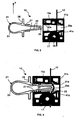
figures 1, 2 ,5 et 6 . Sur lesfigures 5 et 6 , uniquement la première partie 15a du boîtier 15 est représentée pour des raisons de clarté. Sur lafigure 1 , les pattes de fixation 13 du dispositif 10 sont tout d'abord clipser sur l'élément 11, plus particulièrement dans les ouvertures 14 prédécoupées dans l'élément 11. - Sur la
figure 5 , le câble 12 est ensuite inséré dans le dispositif 10 à travers le boîtier 15 au niveau du canal de passage 32 et, une fois le dispositif 10 placé au niveau souhaité sur le câble 12, la goupille 21 est insérée dans le logement 29 correspondant. Sur lafigure 6 , les dents 27 des branches latérales 26 de la goupille 21 coopèrent alors avec les crans 30 de retenue, formés à l'intérieur du boîtier 15. Sur lafigure 6 , l'extrémité d'actionnement 25 de la goupille 21 appuie alors sur le câble 12, qui s'enfonce en direction du fond 31 du logement 29, et le câble 12 se trouve alors légèrement déformé, sans être détérioré. - L'insertion de la goupille 21 à l'intérieur du logement 29 est notamment permise par la flexibilité des branches latérales 26 de la goupille 21. Il suffit d'appuyer sur la tête 24 de la goupille 21, selon l'axe X représenté sur la
figure 5 , pour obtenir le rapprochement des branches 26 et le passage dans les crans 30 successifs. Les crans 30, formés à l'intérieur du boîtier 15, et les dents 27 de la goupille 21 sont, de préférence, du type anti-retour, c'est-à-dire que l'insertion de la goupille 21 n'est possible que dans un sens, par déformation des branches latérales 26 de la goupille 21 à chaque passage d'un cran 30. Pour désengager la goupille 21, il est alors nécessaire d'appuyer sur la tête 24, selon l'axe X, afin de désengager l'ensemble des dents 27 des crans 30 et de tirer la goupille 21 dans le sens opposé à l'insertion. - L'enfoncement maximal de la goupille 21 dans le logement 29 est déterminé par les butées 28 faisant saillie des branches latérales 26 de la goupille 21 et venant en contact contre le bord associé du boîtier 15. Les butées 28 étant placées sur les branches latérales 26 de la goupille 21, la tête 24 de la goupille 21 est alors destinée à rester à l'extérieur du boîtier 15 du dispositif de positionnement 10, après le blocage du câble 12 à l'intérieur du boîtier 15. Les dents 27 de la goupille 21 permettent ainsi d'empêcher le retour de la goupille 21 à l'extérieur du boîtier 15. Les frottements engendrés par le câble 12 dans son canal de passage 32, plus particulièrement au niveau des portions évasées 41, permettent également d'immobiliser le câble 12.
- Sur les
figures 1 et 2 , l'étape suivante consiste alors à introduire la vis 18 dans le trou 35 correspondant de la partie 15a du boîtier 15, au centre de la plaquette métallique 17, de sorte que le câble 12 se trouve alors emprisonné entre la plaquette métallique 17 et la partie inférieure de la tête 19 de la vis 18 (figure 2 ). Enfin, la vis 18 est fixée dans l'orifice 20 associé de l'élément 11, afin de le rendre solidaire de la plaquette métallique 17 du boîtier 15 du dispositif 10 et de former un ensemble solidaire, composé de la vis 18, de la plaquette 17, du câble 12 et de l'élément 11. - Le dispositif de positionnement 10 d'un élément 11 sur un câble 12, comme décrit ci-dessus, offre donc l'avantage principal de sécuriser la fixation de l'élément 11 sur le câble 12 par des éléments métalliques, à savoir la plaquette 17 et la vis 18. Par ailleurs, le dispositif de positionnement 10 ne nécessite l'utilisation que d'un seul brin de câble 12 et le positionnement du dispositif 10 sur l'élément 11, par encliquetage des pattes de fixation 13, et le blocage du câble 12 par la goupille 21 sont très simples à réaliser et de manière très rapide. Le dispositif 10 selon l'invention est donc très facile à fabriquer et à mettre en oeuvre, tout en restant conforme aux différentes normes de sécurité en vigueur.
- L'invention n'est pas limitée aux différents modes de réalisation décrits ci-dessus. La forme et les dimensions des différents éléments constitutifs du dispositif 10, à savoir le boîtier 15, la goupille 21, la plaquette métallique 17, la vis 18, le canal de passage 32 du boîtier 15, le logement 29 du boîtier 15, etc., dépendent notamment de la taille du câble 12 et de l'élément 11 à positionner sur le câble 12. À titre d'exemple, la plaquette métallique 17 peut être de forme hexagonale et peut comporter, par exemple, uniquement trois pointes d'ancrage 42 réparties régulièrement sur le contour de la plaquette métallique 17.
- Le dispositif peut comporter tout type de moyens de fixation du boîtier 15 sur l'élément 11, tout type de moyens métalliques d'immobilisation du câble 12 par rapport à l'élément 11 et tout type de moyens de verrouillage de la goupille 21 à l'intérieur du logement 29. La goupille 21 peut être formée par un tout autre type d'organe de blocage, tant qu'il comporte des moyens d'accrochage coopérant avec les moyens de retenue prévus à l'intérieur du +bottier 15.
- Par ailleurs, le dispositif de positionnement 10 peut notamment comporter un boîtier 15 monobloc, le logement 29, les crans 30, le fond 31 du logement 29, le canal de passage 32, le chanfrein 33 et les portions évasées 41 sont alors formés en une seule partie, par exemple par moulage. L'élément 11 peut également comporter une pluralité d'ouvertures prédécoupées 14, coopérant avec autant de dispositif de positionnement 10 selon l'invention.
- L'invention s'applique notamment au domaine de la fixation des luminaires industriels, dont les normes de sécurité sont très strictes d'un point de vue incendie. En effet, en cas d'incendie, la tenue mécanique de tout élément suspendu doit être optimal, c'est le cas avec le dispositif 10 selon l'invention qui permet de former un ensemble fixe composé de la vis 18, de la plaquette métallique 17, du câble 12 et de l'élément 11, le boîtier 15 étant en matériau plastique fusible.
- L'invention peut s'appliquer également à la fixation de goulottes métalliques suspendues par des câbles. D'une façon générale, le dispositif de positionnement 10 selon l'invention s'applique à tout élément 11, destiné à être suspendu sur un câble 12 de tout type.
Claims (10)
- Dispositif de positionnement (10) d'un élément (11) sur un câble (12), comportant au moins :- un boîtier (15), dans lequel peut être inséré un câble (12),- et un organe de blocage (21) destiné à bloquer un câble (12) lorsqu'il est inséré dans le boîtier (15), par déformation du câble (12) à l'intérieur du boîtier (15),- un logement (29) dans lequel s'insère l'organe de blocage (21) de telle sorte que lorsque un câble (12) est inséré dans le boîtier (15), celui-ci soit disposé à l'intérieur du boîtier (15) sensiblement perpendiculairement par rapport au logement (29),
et qui comporte également- des moyens de verrouillage de l'organe de blocage (21) dans ledit logement (29),- des moyens de fixation (13) du boîtier (15) permettant de fixer celui-ci sur un élément (11) à positionner sur un câble (12),
caractérisé en ce que le dispositif comporte en outre des moyens métalliques d'immobilisation permettant d'immobiliser le câble (12), lorsque celui-ci est inséré dans le boîtier (15), par rapport à l'élément (11) à positionner sur le câble (12). - Dispositif selon la revendication 1, caractérisé en ce que lesdits moyens de verrouillage comportent des moyens d'accrochage (27) solidaires de l'organe de blocage (21), coopérant avec des moyens de retenue (30), faisant saillie dans ledit logement (29).
- Dispositif selon la revendication 2, caractérisé en ce que lesdits moyens d'accrochage de l'organe de blocage (21) comportent des dents (27) et lesdits moyens de retenue comportent des crans (30) anti-retour.
- Dispositif selon l'une quelconque des revendications 1 à 3, caractérisé en ce que lesdits moyens d'immobilisation comportent au moins :- une plaquette métallique (17), montée dans une cavité (34) du boîtier (15).- et une vis métallique (18) dotée d'une tête (19), ladite vis (18) étant insérée à travers la plaquette métallique (17) dans un trou débouchant (35) et pouvant être fixée dans un orifice (20) associé de l'élément (11) à positionner de telle sorte que le câble (12) soit coincé entre la plaquette métallique (17) et ladite tête (19) de la vis (18), lorsque le câble est inséré dans le boîtier.
- Dispositif selon la revendication 4, caractérisé en ce que la plaquette métallique (17) est immobile en rotation par rapport au boîtier (15).
- Dispositif selon l'une des revendications 4 et 5, caractérisé en ce que la tête (19) de la vis (18) est logée dans un évidement (36) du boîtier (15).
- Dispositif selon l'une quelconque des revendications 1 à 6, caractérisé en ce que le boîtier (15) est muni d'un canai de passage (32) adapté à recevoir un câble (12) comportant au moins une extrémité (33) chanfreinée, au niveau d'un bord du boîtier (15), et des portions évasées (41), débouchant au niveau dudit logement (29).
- Dispositif selon l'une quelconque des revendications 1 à 7, caractérisé en ce que le boîtier (15) comporte deux parties (15a, 15b) articulées par une charnière (16) et superposées, dans une position d'utilisation, pour former au moins ledit logement (29).
- Dispositif selon l'une quelconque des revendications 1 à 8, caractérisé en ce que lesdits moyens de fixation du boîtier (15) sur un élément (11) à positionner comportent deux pattes de fixation (13a, 13b) rigides et une patte de fixation (13c) flexible, destinées à s'encliqueter dans des ouvertures (14) prédéterminées d'un élément (11) à positionner.
- Dispositif selon l'une quelconque des revendications 1 à 9, caractérisé
en ce que l'organe de blocage est une goupille (21) conformée en boucle déformable comportant une tête (24) flexible, une extrémité d'actionnement (25), pouvant venir en contact avec un câble (12) lorsque celui-ci est inséré, et deux branches latérales (26) flexibles reliant la tête (24) et l'extrémité d'actionnement (25).
Applications Claiming Priority (2)
| Application Number | Priority Date | Filing Date | Title |
|---|---|---|---|
| FR0700447A FR2911652B1 (fr) | 2007-01-23 | 2007-01-23 | Dispositif de positionnement d'un element sur un cable. |
| PCT/EP2008/000134 WO2008089891A1 (fr) | 2007-01-23 | 2008-01-10 | Dispositif de positionnement d'un element sur un câble |
Publications (2)
| Publication Number | Publication Date |
|---|---|
| EP2126407A1 EP2126407A1 (fr) | 2009-12-02 |
| EP2126407B1 true EP2126407B1 (fr) | 2010-08-25 |
Family
ID=38255881
Family Applications (1)
| Application Number | Title | Priority Date | Filing Date |
|---|---|---|---|
| EP08706984A Not-in-force EP2126407B1 (fr) | 2007-01-23 | 2008-01-10 | Dispositif de positionnement d'un element sur un cable |
Country Status (6)
| Country | Link |
|---|---|
| EP (1) | EP2126407B1 (fr) |
| AT (1) | ATE479033T1 (fr) |
| DE (1) | DE602008002327D1 (fr) |
| ES (1) | ES2351656T3 (fr) |
| FR (1) | FR2911652B1 (fr) |
| WO (1) | WO2008089891A1 (fr) |
Families Citing this family (1)
| Publication number | Priority date | Publication date | Assignee | Title |
|---|---|---|---|---|
| CN109667887B (zh) * | 2018-12-14 | 2021-03-26 | 中国航空工业集团公司西安飞机设计研究所 | 一种快速固定装置 |
Family Cites Families (6)
| Publication number | Priority date | Publication date | Assignee | Title |
|---|---|---|---|---|
| US694818A (en) * | 1901-04-06 | 1902-03-04 | John M Applegate | Elevator and carrier. |
| JPH0617511U (ja) | 1992-08-12 | 1994-03-08 | 吉田工業株式会社 | 紐締め具 |
| JP3152269B2 (ja) | 1993-04-16 | 2001-04-03 | ワイケイケイ株式会社 | 紐締具 |
| SE514953C2 (sv) * | 1999-09-02 | 2001-05-21 | Peter Thunborg | Linförankringsanordning |
| GB2378980B (en) | 2001-08-23 | 2003-07-30 | Gripple Ltd | Suspending equipment |
| DE10216437B4 (de) * | 2002-04-12 | 2008-11-20 | Trilux-Lenze Gmbh & Co. Kg | Triangelaufhängung für Hängeleuchten |
-
2007
- 2007-01-23 FR FR0700447A patent/FR2911652B1/fr not_active Expired - Fee Related
-
2008
- 2008-01-10 DE DE602008002327T patent/DE602008002327D1/de active Active
- 2008-01-10 WO PCT/EP2008/000134 patent/WO2008089891A1/fr not_active Ceased
- 2008-01-10 AT AT08706984T patent/ATE479033T1/de not_active IP Right Cessation
- 2008-01-10 ES ES08706984T patent/ES2351656T3/es active Active
- 2008-01-10 EP EP08706984A patent/EP2126407B1/fr not_active Not-in-force
Also Published As
| Publication number | Publication date |
|---|---|
| ATE479033T1 (de) | 2010-09-15 |
| DE602008002327D1 (de) | 2010-10-07 |
| EP2126407A1 (fr) | 2009-12-02 |
| FR2911652A1 (fr) | 2008-07-25 |
| WO2008089891A1 (fr) | 2008-07-31 |
| FR2911652B1 (fr) | 2009-02-27 |
| ES2351656T3 (es) | 2011-02-09 |
Similar Documents
| Publication | Publication Date | Title |
|---|---|---|
| EP2079646B1 (fr) | Dispositif de distribution de produit fluide | |
| EP1864045B1 (fr) | Dispositif de fixation à fermeture automatique d'un élément sur un support fixe | |
| EP3060860A1 (fr) | Système de maintien d'au moins un panneau solaire sur un module solaire et module solaire le comportant | |
| FR2883108A1 (fr) | Eclisse de chemin de cables en fils | |
| FR2958461A1 (fr) | Dispositif d'ancrage d'un cable sur un support | |
| FR2848984A1 (fr) | Dispositif de securite pour voilure de parachute | |
| EP2571113B1 (fr) | Dispositif de fixation et de connexion rapide pour connecteur en deux parties | |
| EP1336763B1 (fr) | Dispositif de fixation à pince | |
| EP2126407A1 (fr) | Dispositif de positionnement d'un element sur un câble | |
| WO2004083657A9 (fr) | Dispositif de fixation a pince | |
| EP3693624B1 (fr) | Maillon rapide a obturateur | |
| FR2982338A1 (fr) | Dispositif de fixation d'une conduite sur une cloison | |
| EP2446155B1 (fr) | Dispositif de fixation a ecrou plastique | |
| EP0208582B1 (fr) | Mandrin d'enroulement notamment pour sangle de sécurité | |
| FR3032070A1 (fr) | Systeme de suspension pour cable conducteur aerien | |
| FR2766864A1 (fr) | Dispositif de condamnation d'un ouvrant de vehicule automobile | |
| FR2783645A1 (fr) | Dispositif d'ancrage pour ligne aerienne | |
| FR2623857A1 (fr) | Dispositif de fixation pour tubulure ou analogue | |
| FR2783646A1 (fr) | Dispositif d'ancrage pour ligne aerienne suspendue | |
| FR2970308A1 (fr) | Ensemble comprenant un support, un organe rapporte et un insert de liaison, et son procede de montage | |
| EP3726074A1 (fr) | Mousqueton avec organe de délimitation interne | |
| FR2963963A1 (fr) | Dispositif de fixation d'un corps de chauffe et procede d'installation d'un corps de chauffe | |
| FR3039073A1 (fr) | Dispositif d'accrochage a un cable de transport | |
| FR3066561A1 (fr) | Ferrure formant fusible pour un systeme d'entrainement en translation d'un verin | |
| FR2887310A1 (fr) | Dispositif de fixation d'un objet tel qu'une plaque a un support adjacent |
Legal Events
| Date | Code | Title | Description |
|---|---|---|---|
| PUAI | Public reference made under article 153(3) epc to a published international application that has entered the european phase |
Free format text: ORIGINAL CODE: 0009012 |
|
| 17P | Request for examination filed |
Effective date: 20090824 |
|
| AK | Designated contracting states |
Kind code of ref document: A1 Designated state(s): AT BE BG CH CY CZ DE DK EE ES FI FR GB GR HR HU IE IS IT LI LT LU LV MC MT NL NO PL PT RO SE SI SK TR |
|
| GRAP | Despatch of communication of intention to grant a patent |
Free format text: ORIGINAL CODE: EPIDOSNIGR1 |
|
| GRAC | Information related to communication of intention to grant a patent modified |
Free format text: ORIGINAL CODE: EPIDOSCIGR1 |
|
| DAX | Request for extension of the european patent (deleted) | ||
| GRAS | Grant fee paid |
Free format text: ORIGINAL CODE: EPIDOSNIGR3 |
|
| GRAA | (expected) grant |
Free format text: ORIGINAL CODE: 0009210 |
|
| AK | Designated contracting states |
Kind code of ref document: B1 Designated state(s): AT BE BG CH CY CZ DE DK EE ES FI FR GB GR HR HU IE IS IT LI LT LU LV MC MT NL NO PL PT RO SE SI SK TR |
|
| REG | Reference to a national code |
Ref country code: GB Ref legal event code: FG4D Free format text: NOT ENGLISH |
|
| REG | Reference to a national code |
Ref country code: CH Ref legal event code: EP |
|
| REG | Reference to a national code |
Ref country code: IE Ref legal event code: FG4D Free format text: LANGUAGE OF EP DOCUMENT: FRENCH |
|
| REF | Corresponds to: |
Ref document number: 602008002327 Country of ref document: DE Date of ref document: 20101007 Kind code of ref document: P |
|
| REG | Reference to a national code |
Ref country code: NL Ref legal event code: VDEP Effective date: 20100825 |
|
| LTIE | Lt: invalidation of european patent or patent extension |
Effective date: 20100825 |
|
| PG25 | Lapsed in a contracting state [announced via postgrant information from national office to epo] |
Ref country code: NO Free format text: LAPSE BECAUSE OF FAILURE TO SUBMIT A TRANSLATION OF THE DESCRIPTION OR TO PAY THE FEE WITHIN THE PRESCRIBED TIME-LIMIT Effective date: 20101125 Ref country code: AT Free format text: LAPSE BECAUSE OF FAILURE TO SUBMIT A TRANSLATION OF THE DESCRIPTION OR TO PAY THE FEE WITHIN THE PRESCRIBED TIME-LIMIT Effective date: 20100825 Ref country code: FI Free format text: LAPSE BECAUSE OF FAILURE TO SUBMIT A TRANSLATION OF THE DESCRIPTION OR TO PAY THE FEE WITHIN THE PRESCRIBED TIME-LIMIT Effective date: 20100825 Ref country code: LT Free format text: LAPSE BECAUSE OF FAILURE TO SUBMIT A TRANSLATION OF THE DESCRIPTION OR TO PAY THE FEE WITHIN THE PRESCRIBED TIME-LIMIT Effective date: 20100825 |
|
| REG | Reference to a national code |
Ref country code: ES Ref legal event code: FG2A Effective date: 20110128 |
|
| PG25 | Lapsed in a contracting state [announced via postgrant information from national office to epo] |
Ref country code: IS Free format text: LAPSE BECAUSE OF FAILURE TO SUBMIT A TRANSLATION OF THE DESCRIPTION OR TO PAY THE FEE WITHIN THE PRESCRIBED TIME-LIMIT Effective date: 20101225 Ref country code: SI Free format text: LAPSE BECAUSE OF FAILURE TO SUBMIT A TRANSLATION OF THE DESCRIPTION OR TO PAY THE FEE WITHIN THE PRESCRIBED TIME-LIMIT Effective date: 20100825 Ref country code: PL Free format text: LAPSE BECAUSE OF FAILURE TO SUBMIT A TRANSLATION OF THE DESCRIPTION OR TO PAY THE FEE WITHIN THE PRESCRIBED TIME-LIMIT Effective date: 20100825 Ref country code: HR Free format text: LAPSE BECAUSE OF FAILURE TO SUBMIT A TRANSLATION OF THE DESCRIPTION OR TO PAY THE FEE WITHIN THE PRESCRIBED TIME-LIMIT Effective date: 20100825 Ref country code: CY Free format text: LAPSE BECAUSE OF FAILURE TO SUBMIT A TRANSLATION OF THE DESCRIPTION OR TO PAY THE FEE WITHIN THE PRESCRIBED TIME-LIMIT Effective date: 20100825 Ref country code: BG Free format text: LAPSE BECAUSE OF FAILURE TO SUBMIT A TRANSLATION OF THE DESCRIPTION OR TO PAY THE FEE WITHIN THE PRESCRIBED TIME-LIMIT Effective date: 20101125 |
|
| REG | Reference to a national code |
Ref country code: IE Ref legal event code: FD4D |
|
| PG25 | Lapsed in a contracting state [announced via postgrant information from national office to epo] |
Ref country code: LV Free format text: LAPSE BECAUSE OF FAILURE TO SUBMIT A TRANSLATION OF THE DESCRIPTION OR TO PAY THE FEE WITHIN THE PRESCRIBED TIME-LIMIT Effective date: 20100825 Ref country code: SE Free format text: LAPSE BECAUSE OF FAILURE TO SUBMIT A TRANSLATION OF THE DESCRIPTION OR TO PAY THE FEE WITHIN THE PRESCRIBED TIME-LIMIT Effective date: 20100825 Ref country code: GR Free format text: LAPSE BECAUSE OF FAILURE TO SUBMIT A TRANSLATION OF THE DESCRIPTION OR TO PAY THE FEE WITHIN THE PRESCRIBED TIME-LIMIT Effective date: 20101126 Ref country code: NL Free format text: LAPSE BECAUSE OF FAILURE TO SUBMIT A TRANSLATION OF THE DESCRIPTION OR TO PAY THE FEE WITHIN THE PRESCRIBED TIME-LIMIT Effective date: 20100825 |
|
| PG25 | Lapsed in a contracting state [announced via postgrant information from national office to epo] |
Ref country code: IE Free format text: LAPSE BECAUSE OF FAILURE TO SUBMIT A TRANSLATION OF THE DESCRIPTION OR TO PAY THE FEE WITHIN THE PRESCRIBED TIME-LIMIT Effective date: 20100825 Ref country code: DK Free format text: LAPSE BECAUSE OF FAILURE TO SUBMIT A TRANSLATION OF THE DESCRIPTION OR TO PAY THE FEE WITHIN THE PRESCRIBED TIME-LIMIT Effective date: 20100825 |
|
| PG25 | Lapsed in a contracting state [announced via postgrant information from national office to epo] |
Ref country code: EE Free format text: LAPSE BECAUSE OF FAILURE TO SUBMIT A TRANSLATION OF THE DESCRIPTION OR TO PAY THE FEE WITHIN THE PRESCRIBED TIME-LIMIT Effective date: 20100825 Ref country code: CZ Free format text: LAPSE BECAUSE OF FAILURE TO SUBMIT A TRANSLATION OF THE DESCRIPTION OR TO PAY THE FEE WITHIN THE PRESCRIBED TIME-LIMIT Effective date: 20100825 Ref country code: RO Free format text: LAPSE BECAUSE OF FAILURE TO SUBMIT A TRANSLATION OF THE DESCRIPTION OR TO PAY THE FEE WITHIN THE PRESCRIBED TIME-LIMIT Effective date: 20100825 Ref country code: SK Free format text: LAPSE BECAUSE OF FAILURE TO SUBMIT A TRANSLATION OF THE DESCRIPTION OR TO PAY THE FEE WITHIN THE PRESCRIBED TIME-LIMIT Effective date: 20100825 |
|
| PLBE | No opposition filed within time limit |
Free format text: ORIGINAL CODE: 0009261 |
|
| STAA | Information on the status of an ep patent application or granted ep patent |
Free format text: STATUS: NO OPPOSITION FILED WITHIN TIME LIMIT |
|
| BERE | Be: lapsed |
Owner name: A. RAYMOND ET CIE. Effective date: 20110131 |
|
| 26N | No opposition filed |
Effective date: 20110526 |
|
| PG25 | Lapsed in a contracting state [announced via postgrant information from national office to epo] |
Ref country code: MC Free format text: LAPSE BECAUSE OF NON-PAYMENT OF DUE FEES Effective date: 20110131 |
|
| REG | Reference to a national code |
Ref country code: DE Ref legal event code: R097 Ref document number: 602008002327 Country of ref document: DE Effective date: 20110526 |
|
| PG25 | Lapsed in a contracting state [announced via postgrant information from national office to epo] |
Ref country code: BE Free format text: LAPSE BECAUSE OF NON-PAYMENT OF DUE FEES Effective date: 20110131 |
|
| PG25 | Lapsed in a contracting state [announced via postgrant information from national office to epo] |
Ref country code: MT Free format text: LAPSE BECAUSE OF FAILURE TO SUBMIT A TRANSLATION OF THE DESCRIPTION OR TO PAY THE FEE WITHIN THE PRESCRIBED TIME-LIMIT Effective date: 20100825 |
|
| REG | Reference to a national code |
Ref country code: CH Ref legal event code: PL |
|
| GBPC | Gb: european patent ceased through non-payment of renewal fee |
Effective date: 20120110 |
|
| PG25 | Lapsed in a contracting state [announced via postgrant information from national office to epo] |
Ref country code: GB Free format text: LAPSE BECAUSE OF NON-PAYMENT OF DUE FEES Effective date: 20120110 Ref country code: LI Free format text: LAPSE BECAUSE OF NON-PAYMENT OF DUE FEES Effective date: 20120131 Ref country code: CH Free format text: LAPSE BECAUSE OF NON-PAYMENT OF DUE FEES Effective date: 20120131 |
|
| PG25 | Lapsed in a contracting state [announced via postgrant information from national office to epo] |
Ref country code: LU Free format text: LAPSE BECAUSE OF NON-PAYMENT OF DUE FEES Effective date: 20110110 |
|
| PG25 | Lapsed in a contracting state [announced via postgrant information from national office to epo] |
Ref country code: PT Free format text: LAPSE BECAUSE OF NON-PAYMENT OF DUE FEES Effective date: 20100825 |
|
| PG25 | Lapsed in a contracting state [announced via postgrant information from national office to epo] |
Ref country code: TR Free format text: LAPSE BECAUSE OF FAILURE TO SUBMIT A TRANSLATION OF THE DESCRIPTION OR TO PAY THE FEE WITHIN THE PRESCRIBED TIME-LIMIT Effective date: 20100825 |
|
| PG25 | Lapsed in a contracting state [announced via postgrant information from national office to epo] |
Ref country code: HU Free format text: LAPSE BECAUSE OF FAILURE TO SUBMIT A TRANSLATION OF THE DESCRIPTION OR TO PAY THE FEE WITHIN THE PRESCRIBED TIME-LIMIT Effective date: 20100825 |
|
| REG | Reference to a national code |
Ref country code: DE Ref legal event code: R082 Ref document number: 602008002327 Country of ref document: DE |
|
| REG | Reference to a national code |
Ref country code: FR Ref legal event code: PLFP Year of fee payment: 9 |
|
| REG | Reference to a national code |
Ref country code: FR Ref legal event code: PLFP Year of fee payment: 10 |
|
| REG | Reference to a national code |
Ref country code: FR Ref legal event code: PLFP Year of fee payment: 11 |
|
| PGFP | Annual fee paid to national office [announced via postgrant information from national office to epo] |
Ref country code: FR Payment date: 20230124 Year of fee payment: 16 Ref country code: ES Payment date: 20230330 Year of fee payment: 16 |
|
| PGFP | Annual fee paid to national office [announced via postgrant information from national office to epo] |
Ref country code: IT Payment date: 20230120 Year of fee payment: 16 Ref country code: DE Payment date: 20230123 Year of fee payment: 16 |
|
| P01 | Opt-out of the competence of the unified patent court (upc) registered |
Effective date: 20230524 |
|
| REG | Reference to a national code |
Ref country code: DE Ref legal event code: R119 Ref document number: 602008002327 Country of ref document: DE |
|
| PG25 | Lapsed in a contracting state [announced via postgrant information from national office to epo] |
Ref country code: DE Free format text: LAPSE BECAUSE OF NON-PAYMENT OF DUE FEES Effective date: 20240801 |
|
| PG25 | Lapsed in a contracting state [announced via postgrant information from national office to epo] |
Ref country code: FR Free format text: LAPSE BECAUSE OF NON-PAYMENT OF DUE FEES Effective date: 20240131 |
|
| PG25 | Lapsed in a contracting state [announced via postgrant information from national office to epo] |
Ref country code: FR Free format text: LAPSE BECAUSE OF NON-PAYMENT OF DUE FEES Effective date: 20240131 Ref country code: DE Free format text: LAPSE BECAUSE OF NON-PAYMENT OF DUE FEES Effective date: 20240801 |
|
| PG25 | Lapsed in a contracting state [announced via postgrant information from national office to epo] |
Ref country code: IT Free format text: LAPSE BECAUSE OF NON-PAYMENT OF DUE FEES Effective date: 20240110 |
|
| REG | Reference to a national code |
Ref country code: ES Ref legal event code: FD2A Effective date: 20250227 |
|
| PG25 | Lapsed in a contracting state [announced via postgrant information from national office to epo] |
Ref country code: ES Free format text: LAPSE BECAUSE OF NON-PAYMENT OF DUE FEES Effective date: 20240111 |