EP2124347A2 - Funkübertragungsvorrichtung - Google Patents
Funkübertragungsvorrichtung Download PDFInfo
- Publication number
- EP2124347A2 EP2124347A2 EP08172645A EP08172645A EP2124347A2 EP 2124347 A2 EP2124347 A2 EP 2124347A2 EP 08172645 A EP08172645 A EP 08172645A EP 08172645 A EP08172645 A EP 08172645A EP 2124347 A2 EP2124347 A2 EP 2124347A2
- Authority
- EP
- European Patent Office
- Prior art keywords
- peak suppression
- section
- value
- transmission signal
- peak
- Prior art date
- Legal status (The legal status is an assumption and is not a legal conclusion. Google has not performed a legal analysis and makes no representation as to the accuracy of the status listed.)
- Withdrawn
Links
Images

Classifications
-
- H—ELECTRICITY
- H03—ELECTRONIC CIRCUITRY
- H03G—CONTROL OF AMPLIFICATION
- H03G3/00—Gain control in amplifiers or frequency changers
- H03G3/20—Automatic control
- H03G3/30—Automatic control in amplifiers having semiconductor devices
- H03G3/3036—Automatic control in amplifiers having semiconductor devices in high-frequency amplifiers or in frequency-changers
- H03G3/3042—Automatic control in amplifiers having semiconductor devices in high-frequency amplifiers or in frequency-changers in modulators, frequency-changers, transmitters or power amplifiers
-
- H—ELECTRICITY
- H03—ELECTRONIC CIRCUITRY
- H03F—AMPLIFIERS
- H03F1/00—Details of amplifiers with only discharge tubes, only semiconductor devices or only unspecified devices as amplifying elements
- H03F1/32—Modifications of amplifiers to reduce non-linear distortion
- H03F1/3241—Modifications of amplifiers to reduce non-linear distortion using predistortion circuits
-
- H—ELECTRICITY
- H04—ELECTRIC COMMUNICATION TECHNIQUE
- H04W—WIRELESS COMMUNICATION NETWORKS
- H04W52/00—Power management, e.g. Transmission Power Control [TPC] or power classes
- H04W52/04—Transmission power control [TPC]
- H04W52/06—TPC algorithms
- H04W52/16—Deriving transmission power values from another channel
-
- H—ELECTRICITY
- H04—ELECTRIC COMMUNICATION TECHNIQUE
- H04W—WIRELESS COMMUNICATION NETWORKS
- H04W52/00—Power management, e.g. Transmission Power Control [TPC] or power classes
- H04W52/04—Transmission power control [TPC]
- H04W52/30—Transmission power control [TPC] using constraints in the total amount of available transmission power
- H04W52/36—Transmission power control [TPC] using constraints in the total amount of available transmission power with a discrete range or set of values, e.g. step size, ramping or offsets
-
- H—ELECTRICITY
- H04—ELECTRIC COMMUNICATION TECHNIQUE
- H04W—WIRELESS COMMUNICATION NETWORKS
- H04W52/00—Power management, e.g. Transmission Power Control [TPC] or power classes
- H04W52/04—Transmission power control [TPC]
- H04W52/52—Transmission power control [TPC] using AGC [Automatic Gain Control] circuits or amplifiers
Definitions
- the present invention relates to a radio transmission apparatus performing peak suppression processing of a transmission signal having a peak component, and more particularly a radio transmission apparatus improving adjustment accuracy of a gain and a peak suppression value of a transmission signal in response to the variation of transmission power.
- a multicarrier transmission system transmits data by dividing into a plurality of subcarriers in parallel. Because the symbol period can be elongated as compared to a single carrier transmission, deteriorated transmission due to multipath can be reduced. Further, in OFDM (Orthogonal Frequency Division Multiplexing), which is an effective means to achieve multicarrier transmission, high frequency use efficiency and high-speed transmission can be achieved because of signal transmission on a plurality of orthogonal subcarriers.
- OFDM Orthogonal Frequency Division Multiplexing
- the multicarrier transmission system (OFDM in particular) has been put into practical use in terrestrial digital broadcasting, wireless LANs, etc.
- WiMAX Worldwide Interoperability for Microwave Access
- WiMAX is standardized by IEEE 802.16-2004/IEEE802.16e.
- IEEE 802.16-2004/IEEE802.16e IEEE 802.16-2004/IEEE802.16e.
- the radio transmission apparatus generates and transmits an OFDM modulation signal, in which mutually orthogonal subcarrier signals are processed by inverse Fast Fourier Transform (IFFT), to frequency multiplex each subcarrier signal.
- IFFT inverse Fast Fourier Transform
- the OFDM modulation signal generated by the IFFT processing includes a peak component, and PAPR (Peak-to-Average Power Ratio) becomes larger. In other words, as compared to average transmission power, peak transmission power tends to be remarkably large.
- the linearity and the efficiency of the amplifier are characteristics which are contrary to each other.
- power efficiency decreases, and power consumption increases in the radio transmission apparatus. Therefore, in order to limit PAPR, peak suppression processing to suppress peak transmission power has been enforced.
- peak suppression processing there is a known method of executing in two stages : pre-peak suppression processing by a hard clipping method, and post-peak suppression processing by a window function method (Patent document 1).
- the peak suppression processing is also effective to improve an adjacent channel leakage power characteristic, ACLR (Adjacent Channel Leakage Ratio). By setting a peak suppression value according to transmission power, a good ACLR characteristic can be obtained.
- ACLR adjacent Channel Leakage Ratio
- distortion compensation processing is enforced to suppress nonlinear distortion by linealizing the amplification characteristic of the amplifier.
- a digital pre-distortion system is known.
- the principle of the digital pre-distortion system is that a characteristic inverse to an amplifier distortion characteristic is added in advance to an amplifier input signal, so as to obtain a desired signal having no distortion in the amplifier output.
- a distortion compensation coefficient is calculated and updated.
- the distortion compensation coefficient is stored into a memory using transmission signal amplitude, power, or the function thereof, as a memory address.
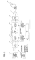
- FIG. 1 is a diagram illustrating the conventional configuration of peak suppression processing in a radio transmission apparatus.
- a transmission signal generation section 1 generates and outputs a digital data string of transmission signals .
- a gain adj ustment section 2 is a means for adjusting, at the stage of the digital data prior to amplification, a transmission signal gain to absorb variation of actual transmission power, radiated from an antenna, caused by performance dispersion of analog circuit components etc. in the radio transmission apparatus.
- a gain coefficient being set into gain adjustment section 2 is preset by a transmission power control section 5.
- Transmission power control section 5 sets the gain coefficient to form the transmission power to be a specified value.
- a pre-peak suppression section 31 in a peak suppression section 3 executes peak suppression processing by the hard clipping method so as to cut a signal portion exceeding a predetermined threshold. Because out-of-band radiation is produced when performing the peak suppression processing by the hard clipping method, band limitation processing is performed by a low pass filter (LPF) 32.
- LPF low pass filter
- a post-peak suppression section 33 executes peak suppression processing by the window function method.
- the peak suppression processing using a window function decreases a peak point to a suppression level by multiplying such a correction coefficient as to produce the peak point exceeding the threshold of the suppression level to be [suppression level/ peak value of an input signal envelope].
- the window function is used as a coefficient for correction.
- the height (the level at the highest portion) of the window function is [suppression level/ peak value of the input signal envelope], and the magnitudes between the start point and the end point are one-fold.
- a DPD section 6 executes distortion compensation processing using the aforementioned digital pre-distortion system. After the peak suppression processing and the distortion compensation processing, the transmission signal is amplified by an amplifier (PA) 7, and transmitted from an antenna 9 through a band pass filter 8.
- PA amplifier
- control section 4 controls the peak suppression value in pre-peak suppression section 31 and post-peak suppression section 33 according to the transmission power.
- control section 4 includes a pre-peak suppression value table 41 having peak suppression values corresponding to transmission power values, to be set to pre-peak suppression section 31, and a post-peak suppression value table 42 having peak suppression values corresponding to the transmission power values, to be set to post-peak suppression section 33.
- Control section 4 also includes a CPU 43 for selecting thresholds from tables 41, 42 according to the transmission power being set by a transmission power control section 5, and for setting the selected thresholds into pre-peak suppression section 31 and post-peak suppression section 33.
- the reason why the peak suppression value is varied according to the transmission power is as follows: in order to make constant the actual transmission power from an antenna end, if the transmission power of a transmission signal (digital data) is adjusted in the prior stage of the peak suppression processing, it is known that the PAPR characteristic varies, causing deterioration of both modulation accuracy (hereafter referred to as EVM, Error Vector Magnitude) and the ACLR.
- EVM Error Vector Magnitude
- tables 41, 42 for storing peak suppression values (thresholds) according to the transmission power values.
- tables 41, 42 have been generated using the peak suppression values corresponding to the transmission power values, individually obtained on an apparatus-by-apparatus basis.
- each peak suppression value to make CCDF to be constant corresponding to each transmission power value is obtained.
- the CCDF is a statistic method for interpreting a signal PAPR characteristic, and by measuring the PAPR characteristic and the CCDF, it is possible to confirm whether adjacent channel leakage power is in an appropriate range.
- the transmission power is increased with a fixed peak suppression value, CCDF is reduced and suppression effect is increased, causing the deterioration of EVM. Also, if the transmission power is decreased with a fixed peak suppression value, CCDF is increased and the suppression effect is decreased, causing the deterioration of ACLR. As such, with the variation of CCDF, the radio transmission characteristics such as EVM, ACLR are deteriorated. Therefore, in response to varied transmission power, by appropriately setting the peak suppression value to make CCDF constant, the deterioration of the radio transmission characteristics such as EVM and ACLR has been prevented.
- Patent document 1 the Japanese Unexamined Patent Publication No. 2007-194825 .
- transmission power having been adjusted at the evaluation stage before shipment from a factory varies.
- actual transmission power becomes different from the transmission power at the time of evaluation before shipment from the factory.
- the modulation scheme varies during operation, and the transmission power also varies depending on the modulation scheme.
- a radio transmission apparatus capable of setting an optimal peak suppression value to a transmission signal, having varied transmission power, with high accuracy without deteriorating a radio transmission characteristic.
- a radio transmission apparatus generating a transmission signal including a peak component, so as to transmit from an antenna, includes: a first gain adjustment section performing gain adjustment by multiplying the transmission signal by a first gain coefficient; a first peak suppression section suppressing the peak component of the transmission signal being output from the first gain adjustment section, according to a first peak suppression value; a low pass filter filtering the transmission signal being output from the first peak suppression section; a second gain adjustment section performing gain adjustment by multiplying the transmission signal being output from the low pass filter by a second gain coefficient; a second peak suppression section suppressing the peak component of the transmission signal being output from the second gain adjustment section, according to a second peak suppression value; and a control section calculating the second gain coefficient and the second peak suppression value based on a variation ratio between transmission signal power being output from the first gain adjustment section and transmission signal power in a posterior stage to the second peak suppression section.
- the radio transmission apparatus executes two stages of peak suppression processing, and executes gain adjustment processing immediately before each stage of the peak suppression processing. Further, there are obtained by calculation a gain coefficient of the gain adjustment processing in the posterior stage (processing in a second gain adjustment section) and a peak suppression value of the peak suppression processing in the posterior stage (processing in a second peak suppression section), according to the variation ratio of the transmission power.
- aspects of the invention provide a method of generating a transmission signal as well as a program (which may be stored on a medium) for performing the method.
- the radio transmission apparatus enables fine adjustment of the gain coefficient and the peak suppression value in response to the variation of transmission power.
- the gain coefficient and the peak suppression value can be set with high accuracy, without deteriorating the radio transmission characteristic.
- the radio transmission apparatus is apparatus performing peak suppression processing in the two stages of pre-peak suppression processing and post-peak suppression processing.
- the gain adjustment processing of transmission power is performed in the two stages of coarse gain adjustment processing, prior to the pre-peak suppression processing, and fine gain adjustment processing prior to the post-peak suppression processing.
- the fine gain adjustment processing has a smaller adjustment step width than the coarse gain adjustment processing, and can adjust the transmission power in response to a small variation of the transmission power.
- a peak suppression value corresponding to the gain set by the coarse gain adjustment processing (the transmission power having an adjusted gain) is set on the basis of each value being preset in a table for each transmission power value.
- the peak suppression value corresponding to the gain modified by the fine gain adjustment processing is obtained by calculation.
- the coarse gain adjustment processing has the gain adjustment step width broader than the fine gain adjustment processing. Therefore, with regard to the peak suppression value for the pre-peak suppression processing, it is possible to obtain and store peak suppression values, having a relatively broad adjustment step width, into the table, as conventionally in the evaluation work beforehand. However, by preparing the variation portion of the transmission power, caused by the dispersion of components and the dispersion in the signal line length to an antenna, as an adjustment range of the fine gain adjustment processing, the preparation of the pre-peak suppression value in advance by the table becomes unnecessary.
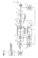
- FIG. 2 is a diagram illustrating a first exemplary configuration of the radio transmission apparatus according to the present embodiment.
- a transmission signal generation section 1 generates and outputs a digital data string, a transmission signal.
- a coarse gain adjustment section 20 is a means for adjusting the transmission signal gain before the pre-peak suppression processing, and virtually has an identical function to gain adjustment section 2 shown in FIG. 1 .
- a gain coefficient set to coarse gain adjustment section 20 is preset by a transmission power control section 5. Transmission power control section 5 sets the gain coefficient so that the transmission power becomes a predetermined value.
- Peak suppression section 3 includes pre-peak suppression section 31 for executing peak suppression processing by the hard clipping method, and a post-peak suppression section 33 for executing peak suppression processing by the window function method.
- the peak suppression processing is executed in two stages.
- the transmission signal whose signal portion exceeding a predetermined threshold is cut by pre-peak suppression section 31 is filtered through a low pass filter (LPF) 32, and then input into fine gain adjustment section 34. After being gain adjusted again, the above transmission signal is input into a post-peak suppression section 33.
- LPF low pass filter
- the peak suppression value to be set to pre-peak suppression section 31 (i.e. pre-peak suppression value) and the peak suppression value to be set to post-peak suppression section 33 (i.e. post-peak suppression value) are controlled by a control section 4.
- Control section 4 has a pre-peak suppression set table 41 storing each pre-peak suppression value for each transmission power value to be set to pre-peak suppression section 31. According to the gain coefficient being set to coarse gain adjustment section 20 by transmission power control section 5, a CPU 43 in control section 4 selects a pre-peak suppression value from table 41, so as to set to pre-peak suppression section 31.
- CPU 43 compares the transmission power of the transmission signal, being output from coarse gain adjustment section 20, with the transmission power of a transmission signal being output from amplifier (PA). Then, based on the difference therebetween, CPU 43 adjusts the gain coefficient to be set to fine gain adjustment section 34, and also obtains by calculation a post-peak suppression value to be set to post-peak suppression section 33 corresponding to the gain coefficient in fine gain adjustment section 34.
- PA amplifier
- a transmission power measurement section 10 measures the transmission power of the transmission signal being output from coarse gain adjustment section 20, and a feedback power measurement section 11 measures the transmission power of the transmission signal being output from amplifier (PA) 7. Both of the above measured transmission power are sent to CPU 43.
- a DPD section 6 executes distortion compensation processing to the transmission signal being output from post-peak suppression section 33 by means of the digital pre-distortion system.
- the transmission signal, to which the peak suppression and the distortion compensation have been processed, is amplified by amplifier (PA) 7. After passing through a band pass filter 8, the transmission signal is transmitted from an antenna 9.
- PA amplifier
- gain adjustment processing and peak suppression value adjustment processing in the radio transmission apparatus according to the present embodiment will be described.
- a pre-peak suppression value to be set to pre-peak suppression section 31 and a post-peak suppression value to be set to post-peak suppression section 33 are obtained for each transmission mode (types of transmission frequency bandwidth, for example, 10 MHz ⁇ 1 wave, 10 MHz ⁇ 2 waves, etc.), and stored into an internal memory means.
- the above preparation processing is performed by an operator.
- the gain coefficient has a different value for each transmission mode, and therefore it is necessary to set the gain coefficient for the each transmission mode.
- the above obtained post-peak suppression value is decided to be an initial value of the post-peak suppression value. Further, based on the obtained pre-peak suppression value, pre-peak suppression value table 41 is generated.
- the pre-peak suppression value related to the transmission power other than the reference transmission power is obtained according to the ratio to the reference transmission power, for each adjustment step width in coarse gain adjustment section 20.
- the balance adjustment between a pre-peak suppression amount and a post-peak suppression amount in order to secure high transmission quality, it is necessary to obtain by manual work of the operator. Therefore, as preparation processing, it is necessary to set the initial value of the post-peak suppression value, as a criterion, by obtaining the pre-peak suppression value and the post-peak suppression value for each transmission mode only to the reference transmission power.
- the gain coefficient and the post-peak suppression value are simultaneously modified after being obtained by calculation, according to the variation ratio of the transmission power.
- the gain coefficient of coarse gain adjustment section 20 is set by the control from transmission power control section 5 (initiated by a set operation by the operator).
- the pre-peak suppression value is set to pre-peak suppression section 31, after CPU 43 in control section 4 selects from pre-peak suppression set table 41, based on the transmission power according to the gain coefficient of coarse gain adjustment section 20.
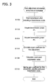
- FIG. 3 is a processing flowchart of the gain coefficient adjustment processing in fine gain adjustment section 34 and the post-peak suppression value adjustment processing in post-peak suppression section 33 executed by the radio transmission apparatus having the first exemplary configuration.
- the present processing is to be processed after the above-mentioned preparation processing in the evaluation work before shipment from the factory.
- the gain coefficient adjustment processing and the peak suppression value adjustment processing are carried out in the state that no DPD processing is performed.
- the processing is started after one transmission mode to be set is selected from among a plurality of transmission modes (types of transmission frequency bandwidth, for example, 10 MHz ⁇ 1 wave, 10 MHz ⁇ 2 waves, etc.) (S100), and a transmission signal is transmitted in the selected transmission mode.
- a plurality of transmission modes types of transmission frequency bandwidth, for example, 10 MHz ⁇ 1 wave, 10 MHz ⁇ 2 waves, etc.
- CPU 43 acquires transmission power P1 of the transmission signal, which is output from coarse gain adjustment section 20 and measured by transmission power measurement section 10 (S102), and further, acquires transmission power P2 of the transmission signal which is output from amplifier 7 and measured by feedback power measurement section 11 (S104).
- the measured power is average power.
- a specified value given in advance from transmission power control section 5 may be used, in place of the power measured by transmission power measurement section 10.
- the gain coefficient Gstd being presently set is a gain coefficient Gchg calculated in the gain adjustment processing performed in the previous time, and has an initial value "1" (at the time of the evaluation work before shipment from the factory, the above initial value "1" becomes Gstd).
- CPU 43 calculates the post-peak suppression value (S108).
- Rstd to be a post-peak suppression value being presently set in post-peak suppression section 33 value
- Rchg to be a newly calculated post-peak suppression value
- the post-peak suppression value Rchg is obtained from the following equation (2).
- Rchg Gchg / Gstd ⁇ Rstd
- the post-peak suppression value Rstd being presently set is a post-peak suppression value Rchg calculated in the post-peak suppression value adjustment processing performed in the previous time.
- the initial value is a post-peak suppression value obtained correspondingly to the above-mentioned reference transmission power to the selected transmission mode. (At the time of the evaluation work before shipment from the factory, the above initial value becomes Rstd.)
- CPU 43 sets the gain coefficient obtained in S106 to fine gain adjustment section 34, and also sets the post-peak suppression value obtained in S108 to post-peak suppression section 33 (S110).
- the post-peak suppression value being set in post-peak suppression section 33 is modified according to the variation ratio of the gain coefficient in fine gain adjustment section 34, without modifying the pre-peak suppression value.
- the peak suppression value can be adjusted at a smaller adjustment step width, without causing deterioration of the radio transmission characteristic such as EVM and ACLR.
- fine gain adjustment section 34 obtains the gain coefficient by the calculation according to power difference, it becomes possible to set the gain coefficient in a smaller adjustment step width (with a step of 0.1 dB, for example). Further, since the peak suppression amount in the post-peak suppression section 33 by the window function method is approximately 1 dB in maximum, in case of adjustment up to ⁇ 0.5 dB, or of that order, with a step of 0.1 dB, it is easy to calculate the post-peak suppression value corresponding to the variation in the gain coefficient with a step of 0.1 dB. Thus, it is appropriate to process the gain adjustment using fine gain adjustment section 34 in combination with the post-peak suppression processing by post-peak suppression section 33.
- fine gain adjustment section 34 is disposed in a posterior stage to pre-peak suppression section 31 and also, in a prior stage to post-peak suppression section 33. Additionally, in regard to such a relatively large variation of the transmission power as exceeding 1 dB, the gain adjustment may be performed in coarse gain adjustment section 20.
- CPU 43 may modify and reset the peak suppression value to be set to pre-peak suppression section 31, based on pre-peak suppression set table 41.
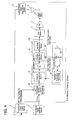
- FIG. 4 is a diagram illustrating a second exemplary configuration of the radio transmission apparatus according to the present embodiment.
- the second exemplary configuration includes an antenna output power measurement unit 12 for directly measuring the transmission power of the transmission signal being output from antenna 9.
- Other configuration elements are similar to the elements in the first exemplary configuration.
- the first exemplary configuration is a configuration for the gain adjustment processing and the peak suppression value adjustment processing executed at the time of evaluation work before shipment from the factory.
- the second exemplary configuration is a configuration for the gain adjustment processing and the peak suppression value adjustment processing, to be executed at a location in which the radio transmission apparatus is actually installed.
- the transmission signal being output from antenna 9 is directly measured, it becomes possible to perform the peak suppression value adjustment, in response to the variation of the transmission power caused by the dispersion in a passing loss due to the difference in the cable length to antenna 9, and the dispersion in the passing loss of the entire components on the transmission signal path disposed at a posterior stage to amplifier 7, such as band pass filter 8.
- the adjustment processing at the time of the evaluation work before shipment from the factory using the first exemplary configuration shown in FIG. 2 and also the adjustment processing at the installation location using the second exemplary configuration, it becomes possible to adjust the gain and the peak suppression value with higher accuracy.
- FIG. 5 is a processing flowchart of the gain coefficient adjustment processing in fine gain adjustment section 34 and the post-peak suppression value adjustment processing in post-peak suppression section 33, in the radio transmission apparatus having the second exemplary configuration.
- the processing is started after one transmission mode to be set is selected from among a plurality of transmission modes (types of transmission frequency bandwidth, for example, 10 MHz ⁇ 1 wave, 10 MHz ⁇ 2 waves, etc.) (S200) and a transmission signal is transmitted in the selected transmission mode.
- a plurality of transmission modes types of transmission frequency bandwidth, for example, 10 MHz ⁇ 1 wave, 10 MHz ⁇ 2 waves, etc.
- transmission power control section 5 acquires transmission power P2 measured by antenna output power measurement unit 12 (S202). Transmission power control section 5 then notifies CPU 43 of a specified value P1 of the transmission power from antenna 9 and the measured power P2, so as to instruct to execute fine adjustment processing (S204).
- a gain coefficient Gchg to be newly calculated is calculated from the above-mentioned equation (1).
- the gain coefficient Gstd is Gchg having been obtained in the evaluation work performed before shipment from the factory, whose value is stored in the internal memorymeans of control section 4.
- the updated Gchg is stored in the internal memory means in an overwritten manner.
- CPU 43 calculates a post-peak suppression value (S208).
- the newly calculated post-peak suppression value Rchg is obtained by the above equation (2).
- the presently set post-peak suppression value Rstd is Rchg which is obtained at the time of the evaluation work performed before shipment from the factory, whose value is stored in the internal memory means of control section 4.
- the updated Rchg is stored in the internal memory means in an overwritten manner.
- CPU 43 sets the gain coefficient obtained in S206 to fine gain adjustment section 34, and also sets the post-peak suppression value obtained in S208 to post-peak suppression section 33 (S210).
- transmission power control section 5 acquires transmission power P2 measured by antenna output power measurement unit 12 (S212). It is decided whether or not the measured transmission power P2 is consistent with the specified value P1 of the transmission power (within a tolerable error) (S214), and in case of inconsistency, the processing of the above steps S204 through S212 is repeated. In case of consistency, the processing is completed.
- the transmission power measured by antenna output power measurement unit 12 is acquired by transmission power control section 5, and reported from transmission power control section 5 to CPU 43 in control section 4. However, it is also possible to configure to acquire directly by CPU 43 (dotted line in the figure).
- the specified value of the transmission power is also stored in advance in the internal memory means of control section 4. Further, with the provision of power measurement section 10 in the first configuration shown in FIG. 2 , it may also be possible to use power (transmission signal power being output from coarse gain adjustment section 20) measured by power measurement section 10, in place of the specified value of the transmission power.
- the gain coefficient in fine gain adjustment section 34 is obtained by calculation in response to the variation of the transmission power, and further, according to the above gain coefficient, a post peak suppression value in post peak suppression section 33 can automatically be obtained by calculation, without deteriorating the radio transmission characteristic.
- the adjustment work at the installation location becomes easy and the adjustment time can greatly be reduced.
- the peak suppression value can be adjusted flexibly to the dispersion of component characteristics, the use of an expensive component having small dispersion becomes unnecessary, which leads to the cost reduction of the radio transmission apparatus.
Landscapes
- Engineering & Computer Science (AREA)
- Physics & Mathematics (AREA)
- Nonlinear Science (AREA)
- Power Engineering (AREA)
- Computer Networks & Wireless Communication (AREA)
- Signal Processing (AREA)
- Transmitters (AREA)
- Control Of Amplification And Gain Control (AREA)
Applications Claiming Priority (1)
| Application Number | Priority Date | Filing Date | Title |
|---|---|---|---|
| JP2008131592A JP2009284044A (ja) | 2008-05-20 | 2008-05-20 | 無線送信装置 |
Publications (1)
| Publication Number | Publication Date |
|---|---|
| EP2124347A2 true EP2124347A2 (de) | 2009-11-25 |
Family
ID=41024574
Family Applications (1)
| Application Number | Title | Priority Date | Filing Date |
|---|---|---|---|
| EP08172645A Withdrawn EP2124347A2 (de) | 2008-05-20 | 2008-12-22 | Funkübertragungsvorrichtung |
Country Status (3)
| Country | Link |
|---|---|
| US (1) | US20090291653A1 (de) |
| EP (1) | EP2124347A2 (de) |
| JP (1) | JP2009284044A (de) |
Families Citing this family (8)
| Publication number | Priority date | Publication date | Assignee | Title |
|---|---|---|---|---|
| WO2008088859A2 (en) * | 2007-01-18 | 2008-07-24 | Mobileaccess Networks Ltd. | Hybrid passive active broadband antenna for a distributed antenna system |
| US9276656B2 (en) * | 2007-02-19 | 2016-03-01 | Corning Optical Communications Wireless Ltd | Method and system for improving uplink performance |
| JP5262361B2 (ja) * | 2008-07-03 | 2013-08-14 | 富士通株式会社 | ピーク抑圧復元方法、送信装置、受信装置、およびピーク抑圧復元システム |
| US20110223963A1 (en) * | 2010-03-12 | 2011-09-15 | Quantance, Inc. | Maximum transmit power controller |
| IL212379A0 (en) * | 2010-04-19 | 2011-06-30 | Designart Networks Ltd | A method and apparatus crest-factor reduction in telecommunications systems |
| US9014319B1 (en) * | 2013-11-22 | 2015-04-21 | Xilinx, Inc. | Cancellation pulse crest factor reduction |
| EP3202199B1 (de) * | 2014-09-30 | 2020-03-25 | Telefonaktiebolaget LM Ericsson (publ) | Bestimmung einer mittenfrequenz in einem unlizenzierten frequenzband zur verwendung |
| CN110022598B (zh) * | 2018-01-08 | 2023-08-08 | 深圳市中兴微电子技术有限公司 | 一种功率控制方法、终端和计算机可读存储介质 |
Citations (1)
| Publication number | Priority date | Publication date | Assignee | Title |
|---|---|---|---|---|
| JP2007194825A (ja) | 2006-01-18 | 2007-08-02 | Fujitsu Ltd | マルチキャリア信号送信装置 |
Family Cites Families (2)
| Publication number | Priority date | Publication date | Assignee | Title |
|---|---|---|---|---|
| US7013161B2 (en) * | 2002-09-24 | 2006-03-14 | Nortel Networks Limited | Peak power reduction using windowing and filtering |
| EP1821474B1 (de) * | 2006-02-17 | 2012-05-30 | Fujitsu Limited | Einrichtung zum Entfernen von Spitzenspannungsignalen |
-
2008
- 2008-05-20 JP JP2008131592A patent/JP2009284044A/ja not_active Withdrawn
- 2008-12-22 EP EP08172645A patent/EP2124347A2/de not_active Withdrawn
- 2008-12-23 US US12/342,417 patent/US20090291653A1/en not_active Abandoned
Patent Citations (1)
| Publication number | Priority date | Publication date | Assignee | Title |
|---|---|---|---|---|
| JP2007194825A (ja) | 2006-01-18 | 2007-08-02 | Fujitsu Ltd | マルチキャリア信号送信装置 |
Also Published As
| Publication number | Publication date |
|---|---|
| JP2009284044A (ja) | 2009-12-03 |
| US20090291653A1 (en) | 2009-11-26 |
Similar Documents
| Publication | Publication Date | Title |
|---|---|---|
| EP2124347A2 (de) | Funkübertragungsvorrichtung | |
| JP5427300B2 (ja) | べき級数型ディジタルプリディストータとその制御方法 | |
| US9077299B2 (en) | Pre-distortion for fast power transient waveforms | |
| JP4855267B2 (ja) | 信号取出回路およびそれを有する歪み補償増幅器 | |
| EP3334040B1 (de) | Vorrichtung und verfahren zur segmentierten digitalen vorverzerrung | |
| US7915969B2 (en) | Distortion compensating circuit | |
| CN101133550B (zh) | 任意波形预矫正表生成 | |
| US8000661B2 (en) | Communication system with frequency-adaptive predistorter design | |
| US20070188218A1 (en) | Peak power suppressor and peak power suppressing method | |
| JPH11312928A (ja) | 増幅前の信号の特殊用途の歪に対する方法および装置 | |
| EP2136524B1 (de) | Amplitudenunterdrückungsvorrichtung und Signalübertragungsvorrichtung | |
| US8314656B2 (en) | Power series digital predistorter and distortion compensation control method thereof | |
| US20120134399A1 (en) | Systems and Methods of Improved Power Amplifier Efficiency Through Adjustments in Crest Factor Reduction | |
| KR100811564B1 (ko) | 데카르트 루프 송신기 및 이 송신기의 출력 레벨을조절하는 방법 | |
| CN101969423A (zh) | 一种峰值因子消减方法和装置以及一种射频拉远系统 | |
| JP2013115594A (ja) | 電力増幅器および増幅制御方法 | |
| US8031803B2 (en) | Transmitter capable of suppressing peak of transmission signal | |
| JP2003198273A (ja) | 増幅回路 | |
| Farabegoli et al. | Advanced transmitters with combined crest factor reduction and digital predistortion techniques | |
| EP1318612A2 (de) | Nichtlineare Kompensationsschaltung, Basisstationsvorrichtung, und Verfahren zur Sendeleistungsbegrenzung | |
| JP2008294598A (ja) | 通信装置 | |
| Li et al. | Frequency-dependent DPD linearization for load-mismatched mobile terminal PAs operating under dynamic resource block allocation | |
| JP2009200840A (ja) | 送信装置 | |
| Melvin et al. | Improved compensation of HPA nonlinearities using digital predistorters with dynamic and multi-dimensional LUTs | |
| Suzuki et al. | PAPR Reduction Method for Digital Predistortion Linearizer Compensating for Frequency Dependent IMD Components |
Legal Events
| Date | Code | Title | Description |
|---|---|---|---|
| PUAI | Public reference made under article 153(3) epc to a published international application that has entered the european phase |
Free format text: ORIGINAL CODE: 0009012 |
|
| AK | Designated contracting states |
Kind code of ref document: A2 Designated state(s): AT BE BG CH CY CZ DE DK EE ES FI FR GB GR HR HU IE IS IT LI LT LU LV MC MT NL NO PL PT RO SE SI SK TR |
|
| AX | Request for extension of the european patent |
Extension state: AL BA MK RS |
|
| STAA | Information on the status of an ep patent application or granted ep patent |
Free format text: STATUS: THE APPLICATION IS DEEMED TO BE WITHDRAWN |
|
| 18D | Application deemed to be withdrawn |
Effective date: 20110701 |