EP2122200B1 - Engrenage - Google Patents
Engrenage Download PDFInfo
- Publication number
- EP2122200B1 EP2122200B1 EP08701546A EP08701546A EP2122200B1 EP 2122200 B1 EP2122200 B1 EP 2122200B1 EP 08701546 A EP08701546 A EP 08701546A EP 08701546 A EP08701546 A EP 08701546A EP 2122200 B1 EP2122200 B1 EP 2122200B1
- Authority
- EP
- European Patent Office
- Prior art keywords
- transmission
- option
- unit
- transmission unit
- main
- Prior art date
- Legal status (The legal status is an assumption and is not a legal conclusion. Google has not performed a legal analysis and makes no representation as to the accuracy of the status listed.)
- Active
Links
- 230000005540 biological transmission Effects 0.000 title claims abstract description 732
- 238000009434 installation Methods 0.000 claims abstract description 12
- 238000004519 manufacturing process Methods 0.000 claims abstract description 9
- 230000002441 reversible effect Effects 0.000 claims description 15
- 238000013461 design Methods 0.000 claims description 8
- 230000008878 coupling Effects 0.000 description 22
- 238000010168 coupling process Methods 0.000 description 22
- 238000005859 coupling reaction Methods 0.000 description 22
- 241000219098 Parthenocissus Species 0.000 description 8
- 230000006978 adaptation Effects 0.000 description 5
- 230000000712 assembly Effects 0.000 description 5
- 238000000429 assembly Methods 0.000 description 5
- 230000008859 change Effects 0.000 description 4
- 238000002485 combustion reaction Methods 0.000 description 4
- 238000010276 construction Methods 0.000 description 3
- 230000001186 cumulative effect Effects 0.000 description 3
- 238000010586 diagram Methods 0.000 description 3
- 239000002828 fuel tank Substances 0.000 description 3
- 230000000295 complement effect Effects 0.000 description 2
- 230000002349 favourable effect Effects 0.000 description 2
- 239000012530 fluid Substances 0.000 description 2
- 238000011990 functional testing Methods 0.000 description 2
- 238000000034 method Methods 0.000 description 2
- 230000001360 synchronised effect Effects 0.000 description 2
- 238000004891 communication Methods 0.000 description 1
- 230000001419 dependent effect Effects 0.000 description 1
- 238000011161 development Methods 0.000 description 1
- 230000018109 developmental process Effects 0.000 description 1
- 238000006073 displacement reaction Methods 0.000 description 1
- 230000004907 flux Effects 0.000 description 1
- 230000006872 improvement Effects 0.000 description 1
- 239000007788 liquid Substances 0.000 description 1
- 238000005461 lubrication Methods 0.000 description 1
- 238000012423 maintenance Methods 0.000 description 1
- 238000012986 modification Methods 0.000 description 1
- 230000004048 modification Effects 0.000 description 1
- 238000007789 sealing Methods 0.000 description 1
- 238000013519 translation Methods 0.000 description 1
Images


Classifications
-
- F—MECHANICAL ENGINEERING; LIGHTING; HEATING; WEAPONS; BLASTING
- F16—ENGINEERING ELEMENTS AND UNITS; GENERAL MEASURES FOR PRODUCING AND MAINTAINING EFFECTIVE FUNCTIONING OF MACHINES OR INSTALLATIONS; THERMAL INSULATION IN GENERAL
- F16H—GEARING
- F16H37/00—Combinations of mechanical gearings, not provided for in groups F16H1/00 - F16H35/00
- F16H37/02—Combinations of mechanical gearings, not provided for in groups F16H1/00 - F16H35/00 comprising essentially only toothed or friction gearings
- F16H37/04—Combinations of toothed gearings only
-
- B—PERFORMING OPERATIONS; TRANSPORTING
- B60—VEHICLES IN GENERAL
- B60K—ARRANGEMENT OR MOUNTING OF PROPULSION UNITS OR OF TRANSMISSIONS IN VEHICLES; ARRANGEMENT OR MOUNTING OF PLURAL DIVERSE PRIME-MOVERS IN VEHICLES; AUXILIARY DRIVES FOR VEHICLES; INSTRUMENTATION OR DASHBOARDS FOR VEHICLES; ARRANGEMENTS IN CONNECTION WITH COOLING, AIR INTAKE, GAS EXHAUST OR FUEL SUPPLY OF PROPULSION UNITS IN VEHICLES
- B60K17/00—Arrangement or mounting of transmissions in vehicles
- B60K17/04—Arrangement or mounting of transmissions in vehicles characterised by arrangement, location, or kind of gearing
- B60K17/06—Arrangement or mounting of transmissions in vehicles characterised by arrangement, location, or kind of gearing of change-speed gearing
- B60K17/08—Arrangement or mounting of transmissions in vehicles characterised by arrangement, location, or kind of gearing of change-speed gearing of mechanical type
-
- F—MECHANICAL ENGINEERING; LIGHTING; HEATING; WEAPONS; BLASTING
- F16—ENGINEERING ELEMENTS AND UNITS; GENERAL MEASURES FOR PRODUCING AND MAINTAINING EFFECTIVE FUNCTIONING OF MACHINES OR INSTALLATIONS; THERMAL INSULATION IN GENERAL
- F16H—GEARING
- F16H37/00—Combinations of mechanical gearings, not provided for in groups F16H1/00 - F16H35/00
- F16H37/02—Combinations of mechanical gearings, not provided for in groups F16H1/00 - F16H35/00 comprising essentially only toothed or friction gearings
- F16H37/04—Combinations of toothed gearings only
- F16H37/042—Combinations of toothed gearings only change gear transmissions in group arrangement
-
- F—MECHANICAL ENGINEERING; LIGHTING; HEATING; WEAPONS; BLASTING
- F16—ENGINEERING ELEMENTS AND UNITS; GENERAL MEASURES FOR PRODUCING AND MAINTAINING EFFECTIVE FUNCTIONING OF MACHINES OR INSTALLATIONS; THERMAL INSULATION IN GENERAL
- F16H—GEARING
- F16H57/00—General details of gearing
- F16H57/02—Gearboxes; Mounting gearing therein
- F16H57/033—Series gearboxes, e.g. gearboxes based on the same design being available in different sizes or gearboxes using a combination of several standardised units
-
- F—MECHANICAL ENGINEERING; LIGHTING; HEATING; WEAPONS; BLASTING
- F16—ENGINEERING ELEMENTS AND UNITS; GENERAL MEASURES FOR PRODUCING AND MAINTAINING EFFECTIVE FUNCTIONING OF MACHINES OR INSTALLATIONS; THERMAL INSULATION IN GENERAL
- F16H—GEARING
- F16H57/00—General details of gearing
- F16H57/02—Gearboxes; Mounting gearing therein
- F16H2057/02013—Extension units for gearboxes, e.g. additional units attached to a main gear
-
- F—MECHANICAL ENGINEERING; LIGHTING; HEATING; WEAPONS; BLASTING
- F16—ENGINEERING ELEMENTS AND UNITS; GENERAL MEASURES FOR PRODUCING AND MAINTAINING EFFECTIVE FUNCTIONING OF MACHINES OR INSTALLATIONS; THERMAL INSULATION IN GENERAL
- F16H—GEARING
- F16H57/00—General details of gearing
- F16H57/02—Gearboxes; Mounting gearing therein
- F16H2057/02039—Gearboxes for particular applications
- F16H2057/02043—Gearboxes for particular applications for vehicle transmissions
- F16H2057/02056—Gearboxes for particular applications for vehicle transmissions for utility vehicles, e.g. tractors or agricultural machines
-
- Y—GENERAL TAGGING OF NEW TECHNOLOGICAL DEVELOPMENTS; GENERAL TAGGING OF CROSS-SECTIONAL TECHNOLOGIES SPANNING OVER SEVERAL SECTIONS OF THE IPC; TECHNICAL SUBJECTS COVERED BY FORMER USPC CROSS-REFERENCE ART COLLECTIONS [XRACs] AND DIGESTS
- Y10—TECHNICAL SUBJECTS COVERED BY FORMER USPC
- Y10T—TECHNICAL SUBJECTS COVERED BY FORMER US CLASSIFICATION
- Y10T29/00—Metal working
- Y10T29/49—Method of mechanical manufacture
- Y10T29/49462—Gear making
- Y10T29/49464—Assembling of gear into force transmitting device
-
- Y—GENERAL TAGGING OF NEW TECHNOLOGICAL DEVELOPMENTS; GENERAL TAGGING OF CROSS-SECTIONAL TECHNOLOGIES SPANNING OVER SEVERAL SECTIONS OF THE IPC; TECHNICAL SUBJECTS COVERED BY FORMER USPC CROSS-REFERENCE ART COLLECTIONS [XRACs] AND DIGESTS
- Y10—TECHNICAL SUBJECTS COVERED BY FORMER USPC
- Y10T—TECHNICAL SUBJECTS COVERED BY FORMER US CLASSIFICATION
- Y10T74/00—Machine element or mechanism
- Y10T74/19—Gearing
- Y10T74/19167—In series plural interchangeably locked nonplanetary units
Definitions
- the invention relates to a transmission for transmitting a torque generated by a drive motor to at least one drive axle of a vehicle.
- the vehicle is in particular an agricultural or industrial utility vehicle, preferably a tractor.
- the transmission comprises at least one main transmission unit, which in itself functions.
- the main transmission unit has a gearbox and / or a group transmission.
- An option transmission module arranged in a closed option transmission module housing can be adapted to the main transmission unit in the form of a gearbox, which, viewed individually or in its own right, is capable of functioning. With the option gearbox module, the function of the gearbox can be extended.
- the main transmission unit and the option transmission module are designed such that the space provided is essentially unchanged even if the option transmission module (14) is adapted to the main transmission unit (12).
- a functioning transmission unit in the sense of the present invention is to be understood in particular as meaning that a torque or a rotational speed, which or which of the transmission unit is supplied via an input interface, is emitted again on an output interface of the transmission unit.
- the gear unit may have at least one switching point, so that the gear unit speed, torque and / or direction of rotation can convert into at least two ratio values or levels.
- Transmissions of the type mentioned are known from the prior art.
- a transmission of the applicant in the series production of tractors of the 6000 series is used, in which a option gearbox module is adapted to a main transmission unit.
- This option transmission module has a modular design and can be put together in a versatile way depending on a customer's request.
- the option transmission module is arranged between the drive motor and the main transmission unit and occupies different space depending on the respective composition of the option transmission module. In a full expansion stage of the transmission almost the entire space between the drive motor and main gear unit is installed with the option gearbox module.
- the option transmission module has only a single function, the space between the drive motor and the main transmission unit is largely unused, since the same frame construction is used for all tractors of this series, and both the drive motor and the main transmission unit are always arranged substantially at the same position relative to the frame construction ,
- the use of a frame construction thus makes it possible, inter alia, that a tractor of a certain series or performance class can be variably adapted to the respective customer requirement, whereby for tractors of this series a large variety of gearboxes can also be represented from an economic point of view.
- the transmission has a plurality of modular transmission units.
- the transmission includes a gear shift module, a group transmission module, and an intermediate transmission module disposed between the gear shift module and the group transmission module.
- a first option includes a creeper and a second option additional range gears.
- the gearbox has the same external dimensions.
- a transmission of the type mentioned above is characterized in that the option transmission module is designed in the form of a stand-alone or per se functioning gearbox, which has its own oil pump and at least one own operating device for Actuate couplings of the option transmission module by means of hydraulic switching elements, and that the option transmission module has a closed option gearbox module housing
- installation space in the sense of the present invention is to be understood in particular as the space or the volume which is occupied by the main transmission unit or by the housing of the main transmission unit.
- the main transmission unit is designed such that the option transmission module can be adapted to it, wherein a predefinable maximum installation space of the transmission formed from option transmission module and main transmission unit is not exceeded regardless of the design or configuration of the option transmission module.
- a predefinable maximum installation space of the transmission formed from option transmission module and main transmission unit is not exceeded regardless of the design or configuration of the option transmission module.
- This can be achieved, for example, by the fact that the option transmission module is always spatially arranged on or in the same predetermined partial area of the transmission.
- the transmission or the main transmission unit is designed such that always the space for the option transmission module is provided by this.
- the transmission components of the main transmission unit can be configured or arranged may be that a torque flow may, for example, from the main transmission unit to the option transmission module and back into the main transmission unit.
- fixed predetermined interfaces can be defined, via which the main transmission unit and the option transmission module are coupled together and via which a torque can be transferred.
- the components or the assemblies of the transmission can be designed such that the resulting torque flow is folded in, ie in the transmission in one direction and at least once in the opposite direction.
- the torque flow essentially runs in one direction, since for every further option a further option module is attached to the transmission along this direction.
- the transmission according to the invention is characterized by a modular concept and when using the transmission according to the invention, it is possible in an advantageous manner to provide for all transmission variants of a vehicle series always the same space, whereby the remaining space of the vehicles of the series can be used effectively, for example by the Arranging a fuel tank between the drive motor and the transmission according to the invention.
- the same fuel tank can always be used for all vehicles of the series, which enables a more cost-effective production of the entire vehicle, since at least the assemblies or components of the vehicle arranged around the transmission according to the invention are always of the same design and therefore cost-effective in larger quantities can be.
- the option transmission module has at least one option unit.
- An option unit can be designed, for example, in the form of at least one coupling unit.
- This coupling unit may comprise a frictionally engaged (asynchronous) clutch, with which the torque flow between the drive motor and the transmission, more precisely the option transmission module, can be interrupted.
- the option transmission module can have an option unit, which is designed in the form of a reversing unit. With this reversal of direction of rotation can be achieved, which is particularly intended for agricultural and industrial commercial vehicles or tractors, since such vehicles often change direction during operation.
- tractors usually have a creeper unit with which the tractor can implement a high torque output at a low speed of travel to the ground, for example when planting.
- a creeper unit can also be designed in the form of an option unit, which can be integrated into the option transmission module.
- a two-stage transmission unit (high-low) as an option unit.
- an option unit makes it possible to immediately switch from a high speed, as is required, for example, in the case of a tractor during a fast drive on a road, to a low speed, as is required, for example, in the fieldwork of a tractor.
- the two-stage gear unit may be configured such that it positive or non-positive, in particular under load, is switchable.
- the option transmission module has a base housing part.
- a base housing part may be designed such that at least one option unit can be adapted thereto.
- the coupling unit is adapted to the base housing part of the option transmission module, as with the coupling unit, the introduction of the output torque from the drive motor is in the transmission, which is provided in a preferred embodiment of the transmission according to the invention for all differently configurable main gear units including option gear modules.
- the base housing part of the option transmission module can have at least one positioning means.
- a further positioning means substantially complementary to this positioning means can be provided.
- the positioning means and the further positioning means are arranged such that the option transmission module can be positioned relative to the main transmission unit with respect to its spatial position and / or orientation when the positioning means come into contact with each other.
- At least one reference surface may be provided on the housing of the main transmission unit as a positioning means, for example on a housing opening with respect to which bearing points or guide bores of the main transmission unit during the manufacture of the Gear can be aligned or relatively positioned and with respect to which on the other hand, the positioning in the adaptation of the option transmission module can take place.
- the positioning means may comprise at least one pin, at least one stop surface and / or at least one edge.
- An option unit of the option transmission module may have a housing part. With the housing part, at least one shaft can be rotatably mounted.
- the housing part can also have a bearing support which can come into contact with at least one housing wall of the option transmission module or with at least one housing wall of the main transmission unit.
- the housing part may form a transmission oil connection to a housing wall and / or to a transmission cover of the main transmission unit. Lubrication of the corresponding option unit can take place via such a transmission oil connection and / or the transmission oil connection can serve for the hydraulic actuation of possibly provided switching components of the option unit.
- the housing part may have a channel with which transmission oil or hydraulic fluid can be passed to a hydraulically actuated switching element.
- the option transmission module is designed such that different options of the option transmission module can be represented by a modular, cumulative adaptation of a plurality of option units together with housing parts or bearing supports. This can be achieved in that the housing parts of the respective option units are mounted together, whereby in particular the function of the option transmission module is expandable.
- the option transmission module together with the option module forming option units is accordingly designed such that all sensibly representable options of the option transmission module all do not exceed a maximum predetermined space, so that the options can be adapted to the main transmission unit. More specifically, a first option unit of the option transmission module is adapted to the base housing part. Furthermore, a further housing part of another option unit is adapted to the base housing part, and so on.
- the respective shafts of the individual option units are preferably arranged essentially coaxially to each other.
- a hollow shaft and an inner shaft arranged therein or two shafts arranged successively in the direction of the rotational axis can be provided.
- Shafts of the individual option units arranged parallel to one another are particularly preferred.
- a transmission housing which receives the main transmission unit.
- the transmission housing may be designed such that the option transmission module is at least largely mountable in the transmission housing.
- the gear housing may expediently have an opening into which the option transmission module can be introduced. This opening may be sealed with a lid or housing cover which may be provided on the option transmission module for sealing the transmission.
- the transmission housing including cover or together with adapted option transmission module in addition to housing cover for this always essentially the same space.
- the gear housing may be formed one or more parts. Under a one-piece gear housing is to be understood in particular that the housing section surrounding the main transmission unit and the option transmission module is made of a part, for example, is made of a cast.
- the gear housing has in this case an opening which can be closed with a lid. In this case - although the gear housing is then formed in total by the main gear unit and the option gear module surrounding housing portion and the lid - yet be understood as a one-piece gear housing.
- the cover closes the gear housing to the outside, but without receiving components of the transmission in itself.
- the gear housing takes on components of the transmission in itself. Through the opening of the transmission housing, the components of the main transmission unit and the option transmission module can be assembled and / or serviced or repaired.
- the transmission housing may be composed of two substantially equal parts, wherein the transmission housing thus assembled receives both the main transmission unit and the option transmission module or at least largely surrounds and may optionally be closed by a cover.
- the transmission housing may also be composed of two parts, wherein the one housing part, the main transmission unit and the other housing part receives the option transmission module or at least largely surrounds. As a result, a simple manufacture or assembly of the transmission is made possible. If the two housing parts are mounted together, the gearbox is at least mostly mounted and basically ready for operation. Also composed of the two housing parts gear housing can be completed by a lid.
- the option transmission module adapted to the main transmission unit or to the transmission housing may protrude partially out of the transmission housing.
- the main gearbox can be mounted in the gearbox housing and possibly checked for function.
- the adaptation of the option gear module can be done later, without the main gear unit is to check function again.
- the main transmission unit or the housing need not be disassembled, it is only the - preferably arranged at an upper area - to remove lid and bring the option transmission module.
- a torque flow can be produced directly or indirectly between the option transmission module and the main transmission unit via a shaft-hub connection or via the clutch unit of the option transmission module.
- a functional test of the transmission according to the invention can follow this.
- the transmission housing is preferably a pump drive for transmission oil, a Wegachsdifferentialgetriebe, an interface for a mechanical single-wheel drive and / or a pregnantachsdifferentialgetriebe adaptable.
- the transmission housing has corresponding fastening points, flanges or the like.
- the Schuachsdifferentialgetriebe is preferably arranged laterally in a mounted on the vehicle state of the transmission and may at least partially extend into the transmission housing, wherein an output shaft of the main transmission unit can transmit direct mechanical power to the Deutschenachsdifferentialgetriebe.
- the option transmission module with a shaft-hub connection is preferably adaptable to the main transmission unit.
- This shaft-hub connection is preferably formed reversible, so it can be subsequently solved again, for example, to dismantle the option transmission module for service purposes of the main transmission unit or subsequently another option transmission module to adapt to the main transmission unit.
- the shaft-hub connection form-fitting or frictional torque-resistant.
- the option transmission module can be reversibly adaptable in or on the main transmission unit in order, for example, to subsequently be able to disassemble the option transmission module from the main transmission unit.
- the main transmission unit may be designed in the form of a continuously variable transmission or a discrete transmission having gearshifts.
- the main transmission unit is a transmission with discrete switching stages.
- differently designed main gear units can be provided. So it is conceivable, for example, that a main transmission unit 9 forward and 3 reverse gears (as 3 gears by 3 groups), 8 forward and 4 reverse gears (as 4 gears by 2 groups), 12 forward and 4 reverse gears than (as 3 gears 4 groups), 12 forward and 4 reverse gears (as 4 gears by 3 groups) or 16 forward gears (as 4 gears by 4 groups).
- the main transmission unit is designed as a three-shaft transmission.
- the three transmission shafts are arranged substantially parallel to each other in the main transmission unit.
- the main transmission unit may include an input shaft, an intermediate shaft and an output shaft.
- the input shaft is formed in the form of a hollow shaft.
- the transmission may be configured such that a torque flow from the input shaft via the intermediate shaft to the output shaft (two gear grips) or takes place directly from the input shaft to the output shaft (a gear handle).
- the power transmission is conducted within the transmission via gear pairs, which are each arranged on two transmission shafts and which have a fixed predetermined center distance to each other. So that a gearbox builds as narrow as possible for a certain power class, the axes of the input and output shafts, especially in tractors, so far are arranged vertically to each other. This is partly because the position of the PTO stub is predetermined for tractors due to various standards and thus a favorable design of the PTO drive train is possible. In this configuration, the translation from the drive motor to the PTO stub is performed with only one gear handle.
- the main transmission unit is configured such that in a state in which the main transmission unit is installed in a vehicle, the position of the output shaft is arranged offset in the horizontal direction and optionally in the vertical direction to the position of the input shaft.
- the main transmission unit may no longer build as narrow as in the above-mentioned and known from the prior art two-shaft transmissions of the case.
- the transmission can be installed flatter in the vehicle, so that, for example, the drive motor of the vehicle or its output shaft can be arranged lower relative to the chassis.
- the hood of the vehicle can also be arranged lower, which is an improvement of Visibility allows.
- the so-called transmission tunnel can be dispensed with, which hitherto has been provided in cabins or on operator platforms of tractors and which considerably restricts the freedom of movement in the leg area of the operator.
- the main transmission unit is configured such that in a state in which the main transmission unit is installed in a vehicle, the position of the intermediate shaft is arranged offset in the vertical direction to the position of the output shaft and / or to the position of the input shaft. It is also conceivable that the main transmission unit is formed such that in a state in which the main transmission unit is installed in a vehicle, the position of the intermediate shaft is arranged offset in the horizontal direction to the position of the input shaft and / or to the position of the output shaft. In other words, the three shafts of the main transmission unit are arranged in a triangular configuration, wherein the input shaft can be arranged in the vertical direction above the output shaft, but with a lower height difference to the output shaft, than hitherto usual.
- the input shaft as well as the output shaft are each equipped with gears and other transmission elements.
- the input shaft and / or the output shaft each have at least one switching device.
- This may be, for example, a switching element for actuating a hydraulic clutch.
- the switching elements for example, a hydraulic line, a shift fork, at least one guide rod and a shift sleeve exhibit. With pressurized fluid, the shift fork guided on the at least one guide rod can be moved such that a shift sleeve is actuated for producing, switching and / or releasing a rotationally fixed connection between a toothed wheel arranged on the respective shaft and the shaft.
- the liquid can be conducted with the hydraulic line to the shift fork or to a corresponding actuating element, for example a piston.
- a switching device usually represents a positive, synchronized switching point. However, it is also conceivable that the switching device is frictionally, so unsynchronised switchable.
- the main transmission unit is designed such that, depending on the switching states of the switching devices, a torque flow can be produced from the input shaft via the intermediate shaft to the output shaft or from the input shaft directly to the output shaft. Accordingly, torque can be transmitted to the main transmission unit by means of two or three gear chains.
- the corresponding switching devices are each arranged at the same position or position at different equipping the individual transmission shafts of the main transmission unit for transmission of different properties. Furthermore, at least one bearing point of a transmission shaft can also be arranged at the same location or position, even if the main transmission unit has different configurations for transmissions of different properties. So if the main transmission unit 9 forward and 3 reverse gears has, required for this switching points and the bearings for the three shafts of the main gear unit are provided at a certain point in the main transmission unit.
- gears and at least one switching device for the gearbox are arranged on the input shaft of the main transmission unit. Accordingly, gears and at least one switching device for a group transmission are arranged on the output shaft of the transmission unit.
- the main transmission unit is designed such that all center distances between the three transmission shafts each have substantially the same value.
- the housing of the main transmission unit or the main transmission unit has a housing opening serving for mounting the option transmission module.
- the option transmission module is inserted into the housing opening.
- the housing opening is preferably configured in cooperation with the option transmission module such that the option transmission module is displaceable in at least one direction relative to the main transmission unit for establishing a shaft-hub connection between the main transmission unit and the option transmission module after a state introduced in the housing opening.
- the main transmission unit is arranged in the vicinity of or proximity to a drive axle of the vehicle, which in tractors is usually the rear axle.
- the term spatial proximity may be understood to mean half the wheelbase.
- the main transmission unit and / or the option transmission module are preferably arranged spatially downstream of the axle differential gearing.
- the main transmission unit and / or the option transmission module is arranged next to the axle differential, wherein the axle differential in this embodiment is not arranged as usual in the center of the vehicle axle, but laterally adjacent to one of the wheels of the axle.
- the main transmission unit and / or the option transmission module is thus arranged in a central region of the respective vehicle axle or extends at least in this area. In this case, however, it can be provided that a drive shaft of this vehicle axle extends through the main transmission unit or through its housing.
- main gear unit may optionally be disposed immediately adjacent to the differential gear, it is not necessary for the main gear unit to be directly in torque flow with the differential gear. It is also conceivable that an output shaft of the option transmission module with the axle differential gear is in direct torque flow. In a preferred embodiment, an output shaft of the main transmission unit with the axle differential is in driving connection. Due to the sibling arrangement of the main transmission unit and / or the option transmission module and the axle differential gear, the transmission components of the vehicle are concentrated in the spatial area of the drive axle of the vehicle, so that in an advantageous manner in a region between the drive axle and another vehicle axle and / or the drive motor space is available, which can be used for other vehicle components.
- the main transmission unit with an optional transmission module optionally adapted thereto is designed such that in the installed state of the main transmission unit, the option transmission module is arranged spatially adjacent to the axle differential.
- Such a configuration can be configured in such a way that, at the level of the drive axle, the axle differential gear and the option transmission module are arranged in the direction of the longitudinal axis of the drive axle in a juxtaposed or consecutive manner. In a region immediately before or behind the drive axle relative to the vehicle longitudinal direction then the main transmission unit is arranged.
- either the main transmission unit or the option transmission module is directly in the torque flow with the axle differential gear of the drive axle.
- a torque flow from the drive motor can be produced via the main transmission unit to the drive axle of the vehicle. More specifically, a torque flow from the drive motor via the option transmission module and the main transmission unit to the drive axle of the vehicle can be produced in this order.
- the main transmission unit and the option transmission module is to be designed accordingly.
- the main transmission unit is arranged downstream of an axle differential.
- the Nachix refers in particular to the spatial arrangement of the main gear unit relative to the axle differential and on the torque flow between the main transmission unit and axle differential.
- the axle differential gear is designed such that with this at least a portion of the output from the main transmission unit power as torque or speed to the drive wheels of the corresponding drive axle is transferable. Normally, almost all of the output from the main transmission unit power is transmitted to the drive wheels of the drive axle. However, if part of the output from the main transmission unit power is transmitted to another drive axle of the vehicle, only the remaining part is transmitted to the drive wheels of the axle differential gear downstream drive axle.
- a transmission interface is provided, via which at least part of the power supplied to the main transmission unit can be transmitted via a further output shaft to a further drive axle of the vehicle.
- the further drive axle can likewise have an axle differential gear. If the vehicle is a tractor, the primary drive axle is the rear axle. The other drive axle is accordingly the front axle of the tractor. Depending on the operating state of the tractor, a specifiable proportion of the torque provided by the drive motor of the tractor is transmitted to the further drive axle on the rear axle and a further predeterminable portion is transmitted to the front axle of the tractor.
- the ratio of the torque components which are transmitted to the two vehicle axles can always be substantially constant.
- the transmission interface can be designed such that a torque flow to the other drive axle off and can be switched on, in a preferred embodiment, the transmission interface operable or designed such that the ratio of the torques, which can be issued to the drive axle and to the further drive axle, can be varied. Accordingly, the transmission interface can be operated as a pregnantachsdifferentialgetriebe.
- the torques transmitted to both drive axles preferably have a ratio of 60:40, namely 60 percent of the torque is transmitted to the rear axle and 40 percent is transmitted to the front axle of the vehicle, which is expedient in the case of a tractor.
- the main transmission unit has a further mechanical interface, which is used to transmit mechanical torque from the main transmission unit and / or the option transmission module and / or the drive motor to an implement adaptable to the vehicle serves.
- Such an interface may be in the form of a power take-off shaft and accordingly compatible with working implements used in the agricultural sector. It is preferably provided that a torque flow from the drive motor takes place directly to the PTO, wherein a PTO can be provided, with which the commonly used speeds of the PTO can be provided. Although the torque flow from the drive motor is instantaneous to the PTO shaft, a corresponding shaft may extend through the main transmission unit and / or the option transmission module.
- the main transmission unit or the option transmission module can be connected to the drive motor via a torsion shaft.
- the housing can the drive motor and the transmission according to the invention be formed separately from each other, so not related in a housing block.
- this torsion wave is designed in such a way that at least one-preferably the first or lowest-natural frequency of the entire transmission lies outside the natural frequency range of the usable speed band. If such a torsion wave is used, it is possible to dispense with a torsional vibration damper or torsional vibration damper arranged between the drive engine and the transmission, so that advantageously the number of components and the costs thereof can be reduced.
- the main transmission unit or the option transmission module can be connected to the drive motor via a drive shaft, wherein a torsion element is preferably provided between the main transmission unit and the drive motor.
- the drive shaft is not designed to dampen torque peaks between the drive motor and transmission, since this is the torsion element is provided, which may be in the form of a torsional vibration damper or a Torsionsschwingungstilgers.
- a torque flow between the drive motor and the main transmission unit can be produced via the torsion shaft or the drive shaft by means of the coupling unit of the option transmission module.
- a torque flow between the drive motor and inventive transmission or option transmission module can be interrupted by means of the coupling unit.
- the clutch unit When the clutch unit is engaged, a torque flow is produced between the drive motor and the option transmission module. That of the option transmission module Torque output to the main transmission unit is then transmitted via the axle differential to the wheels of the vehicle.
- the transmission according to the invention is used for a tractor.
- the gear transmission or the group transmission of the main transmission unit is then designed as a power shift transmission, so that on the one hand required for a tractor high spread of the transmission and on the other hand switching under load is possible.
- a main transmission unit for an agricultural or industrial utility vehicle is characterized by an embodiment, such that an option transmission module according to one of the claims 1 to 11 is adaptable to the main transmission unit.
- the main transmission unit has installation space in or on which the option transmission module is adapted to the main transmission unit, so that the space provided for the main transmission unit remains substantially unchanged even when the option transmission module is adapted to the main transmission unit.
- an option transmission module for a transmission for an agricultural or industrial utility vehicle is characterized by an embodiment, such that the option transmission module to a main transmission unit according to one of the claims 1 to 11 is adaptable. Since either the main transmission unit or the option transmission module is in each case designed such that it or this can be adapted to the respective other element, reference is made to avoid repetition to the preceding part of the description.
- a variety of transmissions can be represented by adapting differently designed option transmission modules to a type of main transmission unit.
- different option transmission modules can be formed, for example, by cumulative adaptation of several option units.
- gears can also be represented by differently shaped main gear units, which will be discussed below.
- the main transmission unit can be designed differently, that the input shaft, intermediate shaft and / or the output shaft with different gears is equipped.
- different main transmission units may, for example, have 9 forward and 3 reverse or 12 forward and 4 reverse, as previously described.
- the main transmission unit is arranged in a preferred embodiment with different equipping the individual transmission shafts of the main transmission unit, the corresponding switching devices respectively at the same location or spatial position.
- the main transmission unit is to be disassembled and provided with a different equipment, such as other gears.
- the bearing points of a transmission shaft are also arranged at different equipping a gear shaft of the main gear unit in each case at the same location or spatial position.
- the same housing can be used for the main transmission unit, which advantageously allows an economic representation of a large number of different transmission.
- different transmission power classes can be formed by the fact that between different main gear units, the center distance between the input shaft and the intermediate shaft and the axial distance between the intermediate shaft and the output shaft is changed, wherein the ratio of the two axial distances, on the one hand between the input shaft and intermediate shaft and on the other hand between the intermediate shaft and the output shaft, remains substantially constant.
- different housing for main gear units are to be provided for different transmission power classes, since the center distances of the input shaft and the output shaft and thus the bearings for these waves are to be varied.
- the switching devices can be arranged at the same locations or spatial positions in different cases of the main gear units.
- the transmission according to the invention according to one of the claims 1 to 11 is preferably used for an agricultural or industrial commercial vehicle, in particular for a tractor.
- the object mentioned above is achieved by the method steps of the manufacturing method according to claim 15.
- the option transmission module is displaced along at least one direction such that a shaft-hub connection is made between the option transmission module and the main transmission unit.
- the option transmission module is fixed to the main transmission unit, preferably to the main transmission unit housing.
- the requirement for the application of the manufacturing method according to the invention is a corresponding design of the main transmission unit and the option transmission module, in such a way that on the one hand the option transmission module in the housing opening of the main transmission unit along at least one direction can be moved or moved.
- an interface in the form of a shaft-hub connection is provided between the main transmission unit and the option transmission module, which can be produced by a displacement of the option transmission module relative to the main transmission unit.
- different option transmission modules are provided, which can be adapted to the main transmission unit.
- a plurality of option units can be assembled to form an option transmission module by fastening one option unit each with its base housing part to a base housing part of another option unit.
- different option transmission modules can be produced modularly and inexpensively with always substantially identical individual components or basic housing parts, without having to provide a separate, possibly complex, overall housing for each differently configured option transmission module.
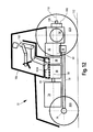
- Fig. 1 and 2 show the same gear 10 in a perspective view, in Fig. 1 without gearbox and in Fig. 2
- the transmission 10 includes at least one main transmission unit 12, which is per se operative, and an option transmission module 14 adapted to the main transmission unit 12.
- the main transmission unit 12 has a gear transmission and a group transmission, which will be discussed later.
- the option transmission module 14 the function of the transmission 10 is expandable, for example, the function of a clutch unit 16, a creeper unit 18 and a two-stage transmission unit (high-low) 20.
- the transmission 10 is used to transmit a generated by a drive motor Torque on at least one drive axle of an agricultural utility vehicle, in particular a tractor, wherein neither the drive motor nor the drive shaft in Fig. 1 and 2 are shown.
- the main transmission unit 12 and the option transmission module 14 are designed such that the installation space provided for the transmission 10 is substantially unchanged even if the option transmission module 14 is adapted to the main transmission unit 12. Regardless of the design or configuration of the option transmission module 14, a predefinable maximum installation space of the transmission 10 formed by the option transmission module 14 and the main transmission unit 12 is not exceeded.
- the option transmission module 14 is always spatially arranged on or in the same predefined partial area of the transmission 10.
- the main transmission unit 12 is formed such that from this always the space for the option transmission module 14 is provided.
- the installation space for the option transmission module 14 is always provided in the transmission housing 11 at the same location, regardless of the configuration of the option transmission module 14 Fig.
- the transmission housing 11 may be formed in one piece. However, the gear housing 11 may also be formed in two or more parts. For example, with the in Fig. 2 . 4 and 15 Dashed line 13 indicated respectively that here the transmission housing 11 can be composed of two housing parts 15 and 17. Fasteners for securing the two housing parts 15 and 17 to each other, such as screws, are in Fig. 2 . 4 and 15 not shown.
- the option transmission module 14 has four option units, a clutch unit 16, a creeper unit 18, a two-stage transmission unit (high-low) 20 and a reversing unit 22.
- the two-stage transmission unit (high-low) 20 is designed such that it is non-positively switchable under load.
- a clutch 23 is shown for the PTO transmission.
- Both the in Fig. 1 and 2 shown as well as in Fig. 3 and 4 shown option transmission module 14 has a base housing part 24. At least the coupling unit 16 is adaptable to this base housing part 24.
- Fig. 5 shows in a perspective view of a base housing part 24, to which only one in Fig. 5 Not shown coupling unit 16 is adaptable. This base housing part 24 is therefore only then accordingly Fig. 5 configured, if in addition to a coupling unit 16 no further option unit of the option transmission module 14 is provided.
- the base housing part 24 of the option transmission module 14 has a plurality of positioning means 26.
- a plurality of positioning means 26 complementary formed further positioning means 28 are provided, which are each designed in the form of a blind hole. Accordingly, the part of a positioning means 26 which is inserted into the blind hole has substantially the shape of a pin.
- the positioning means 26 and the further positioning means 28 are arranged such that the option transmission module 14 can be positioned with respect to its spatial position and orientation relative to the main transmission unit 12 when the positioning means 26, 28 come into contact with each other.
- the positioning means 26, 28 each have a common stop surface 30, 32.
- the stop surface 30 is the in Fig. 1 to 5 concealed bottom surface of the base housing part 24.
- the abutment surface 32 is the in Fig. 2 and 4 shown surface of the gear housing 11, on which a in Fig. 2 and 4 not shown gear cover is adapted.
- the option transmission module 14 can be advantageously adapted to the main transmission unit 12 in an easy and time-saving manner, by first inserting the option transmission module 14 from above into the opening 34 of the transmission housing 11 provided for this purpose. Then, a shaft-hub connection is made between the main transmission unit 12 and the option transmission module 14 and the abutment surfaces 30, 32 of the base housing part 24 and the gear housing 11 come into contact with each other. The positioning means 26 is inserted into the further positioning means 28. As a result, the option transmission module 14 is positioned relative to the main transmission unit 12.
- the option unit or the coupling unit 16 of the option transmission module 14 off Fig. 3 and 4 has a (base) housing part 24, which has a in Fig. 3 and 4 not visible shaft rotatably supports.
- housing part 24 At the in Fig. 5 shown housing part 24 is the bearing 36A for in Fig. 5 also not shown wave of the corresponding option unit shown.
- the housing part 24 has a transmission oil connection 38, which with a in Fig. 3 and 4 not shown gear cover of the transmission case 11 is in communication.
- the housing part 24 accordingly comprises a transmission oil passage extending therein, via which the hydraulic switching element for the clutch unit 16 can be actuated and / or via which the shaft of the clutch unit 16 can be lubricated.
- Different options of the option transmission module 14 can be represented by a modular, cumulative adaptation of several option units together with housing parts.
- the housing parts are designed such that they can be mounted together. This is for example Fig. 6 and 7 removable. Here is in each case on the base housing part 24 Fig. 6 another housing part 40 is mounted.
- Fig. 6 shows next to the housing parts 24, 40, a further housing part 44 of an option transmission module 14, which as option units, the coupling unit 16, the crawler unit 18 and the two-stage gear unit (high-low) 20 has. Between the housing part 44 and the housing part 40, the creeper unit 18 is arranged.
- the creeper unit 18 is arranged for their Shaft bearings 37A and 37B are provided.
- the bearings 36A and 36B are provided.
- the coupling unit 16 and the two-stage gear unit (high-low) 20 is arranged, see for example Fig. 1 to 4 ,
- the bearings 39A and 39B are provided, the bearing 39B is disposed in the housing part 40 and is not visible in this perspective view.
- the housing part 40 also has a bearing point 36B.
- Fig. 7 shows in addition to the in Fig. 6 shown housing parts 24, 40 and 44, a further housing part 42.
- the reversing unit 22 is arranged, see for example Fig. 1 to 4 , For the shaft of the reversing unit 22, the bearing point 39A of the base housing part 24 and the bearing point 39C of the housing part 42 is provided.
- option transmission modules 14 can be provided by mounting corresponding housing parts 24, 40 and 44 together with corresponding option units and then inserting them into the transmission housing 11 of the transmission 10 and connecting them to the main transmission unit 12.
- the function of the option transmission module can be extended in an advantageous manner.
- the transmission housing 11 accommodates the main transmission unit 12, see for example Fig. 3 and 4 ,
- the transmission housing 11 is designed such that the option transmission module 14 is at least largely mountable in the transmission housing 11. Between the option transmission module 14 and the main transmission unit 12, a torque flow can be indirectly produced via the coupling unit 16.
- the rear differential gear 46 is adaptable.
- the Schuachsdifferentialgetriebe 46 is even almost completely housed in the transmission housing 11, wherein the Schuachsdifferentialgetriebe 46 in the direction of travel of in Fig. 1 to 4 not shown tractor on the left side and is not arranged as usual centrally with respect to the rear axle.
- Fig. 2 can be taken that an interface 48 for a mechanical independent drive of the front axle of the tractor is adaptable.
- the option transmission module 14 has its own actuating devices, in particular for actuating clutches of the option transmission module 14 by means of hydraulic shift elements, which are arranged in Fig. 1 to 4 are not visible, but can be switched via the transmission oil connections 38 with pressurized transmission oil.
- the option transmission module 14 is reversibly adaptable to the main transmission unit 12 with a shaft-hub connection 50.
- the shaft-hub connection 50 is in Fig. 1 . 3 and 4 only hinted recognizable and is form-fitting torque-resistant, wherein the option transmission module 14 has a shaft with an external toothing and the adaptable shaft of the main gear unit 12 has a hollow shaft portion with an internal toothing.
- the option transmission module 14 is reversibly adaptable in or on the main transmission unit 12, wherein the option transmission module 14 can also be subsequently removed from the main transmission unit 12, for example to service other components in the transmission housing 11 for service purposes or subsequently a option transmission module 14 with other option units in the Install gearbox 10.
- the main transmission unit 12 is designed as a three-shaft transmission.
- the three transmission shafts 52, 54 and 56 are arranged parallel to each other in the main transmission unit 12. It is the input shaft 52, the intermediate shaft 54 and the output shaft 56.
- the input shaft 52 of the main transmission unit 12 is formed in the form of a hollow shaft.
- Fig. 10A shows in a cross-sectional view transverse to the transmission shafts 58, 60, the usually present configuration of a transmission of a tractor, which has an input shaft 58 and an output shaft 60. Accordingly, the input shaft 58 is disposed in the vertical direction immediately above the output shaft 60. Accordingly, such a transmission builds relatively tall and narrow.
- Fig. 10B shows in a sectional view in a plane transverse to the transmission shafts 52, 54 and 58 of the main transmission unit 12 their spatial arrangement to each other.
- the main transmission unit 12 is configured such that in a state in which the main transmission unit 12 and the transmission 10 are installed in a vehicle, the position of the output shaft 56 is staggered in the horizontal direction and in the vertical direction to the position of the input shaft 52.
- the position of the intermediate shaft 54 in the vertical direction to the position of the output shaft 56 and the position the input shaft 52 is arranged offset.
- the position of the intermediate shaft 54 is arranged offset in the horizontal direction to the position of the input shaft 52 and the position of the output shaft 56. Accordingly, can Fig.
- the main transmission unit 12 does not necessarily build in the vertical direction as high as a transmission known in the prior art, whose input shaft 58 and output shaft 60 directly above each other (see Fig. 10A ). Since the input shaft 52 and the output shaft 56 have the distance 63 in the horizontal direction, the main transmission unit 12 is wider in the horizontal direction than a transmission commonly used in the prior art for a tractor (see, for example Fig. 10A ).
- the center distances 62, 64 and 66 between the three transmission shafts 52, 54 and 56 each have different values, wherein the center distance between the input shaft 52 and the intermediate shaft 54 by the reference numeral 62, the axial distance between the intermediate shaft 54 and the output shaft 56 with the Reference numeral 64 and the axial distance between the output shaft 56 and the input shaft 52 is designated by the reference numeral 66.
- Different transmission power classes can be formed by varying between different main gear units 12, the center distance 62 between the input shaft 52 and the intermediate shaft 54, and the center distance 64 between the intermediate shaft 54 and the output shaft 56, wherein the ratio of the two axial distances 62, 64 on the one hand between the input shaft 52 and intermediate shaft 54 and on the other hand between the intermediate shaft 54 and output shaft 56 remains substantially constant. From such different transmission power classes, a transmission series can be formed.
- the input shaft 52 has two switching devices 68A, 68B.
- the output shaft 56 also has two switching devices 70A, 70B.
- the switching devices 68A, 68B, 70A, 70B are designed to be switchable in a form-fitting, synchronized manner, that is to say each have a shift fork and a shift sleeve.
- Shifting devices 68A, 68B, 70A, 70B shown are each arranged at the same position relative to the transmission housing 11, if the individual transmission shafts 52, 54 and 56 of the main transmission unit 12 for transmission 10 different properties, different, for example, with different gears, equipped.
- bearing points of the transmission shafts 52, 54 and 56 of the main transmission unit 12 are arranged at different locations of the transmission shafts 52, 54 and 56 of the main transmission unit 12 for transmission 10 different properties each at the same position on the transmission housing 11.
- a torque flow from the input shaft 52 via the intermediate shaft 54 to the output shaft 56 or from the input shaft 52 directly to the output shaft 56 can be produced.
- the input shaft 52 has gears and two switching devices 68A, 68B for the gearbox of the tractor, in which the transmission 10 is installed.
- the output shaft 56 includes gears and two group transmission shifting devices 70A, 70B.
- the transmission housing 11 of the main transmission unit 12 has a housing opening 34 serving for mounting the option transmission module 14. For mounting the option transmission module 14, this is introduced into the housing opening 34.
- the housing opening 34 is formed in cooperation with the option transmission module 14 such that the option transmission module 14 can be displaced towards the main transmission unit 12 when it is inserted into the housing opening 34, thus establishing a shaft-hub connection between the main transmission unit 12 and the option transmission module 14 can be.
- Fig. 11 and 12 show in a schematic representation of a plan or a side view of a transmission configuration, as is known in a tractor from the prior art.
- the tractor 72 has an internal combustion engine 74, a front axle 76 and a rear axle 78.
- the front axle 76 is associated with two front wheels 80A, 80B and the rear axle 78 is associated with two rear wheels 82A, 82B.
- the torque generated by the engine 74 is first transmitted to the gearbox 86 via the drive shaft 84.
- the gearbox 86 is an option gear 88 and a group transmission 90 downstream. From the group transmission 90, a torque is transmitted via the rear axle differential gear 92 via the final drive with brake 94 to the rear wheels 82A, 82B. It may, however, be via the mechanical front wheel drive interface 96 and associated drive shaft 98 torque are transmitted to the front wheels 80A, 80B, if it is switched on.
- the area of the driver's cab is designated by the reference numeral 100, the operator of the tractor 72 by the reference numeral 102. Since the input shaft 58 is comparable to Fig. 10A is arranged in a vertical direction above the output shaft 60, which builds in Fig. 11 and 12 shown gear ratios 86, 88 and 90 relatively high, so that the operator 102 in the car 100 to take a comfortable seating position for his legs or feet ultimately only the foot space 104A and 104B left and right next to the gearbox 86 and the option gear 88 remains.
- the PTO gear 106 with the PTO shaft 108 is the rear differential gear 92 downstream.
- Fig. 13 . 14 and 15 can be taken that with the transmission 10 according to the invention advantageously a vehicle configuration can be provided, in which the operator over the entire area 104 is provided transversely to the vehicle longitudinal axis free space for his legs or feet.
- the transmission 10 according to the invention is formed more compact at least with respect to the vehicle longitudinal direction than that in the known from the prior art transmission configuration according to Fig. 11 and 12 the case is.
- Fig. 13 . 14 and particularly Fig. 15 can be seen that between the engine 74 and the transmission 10, the drive shaft 84 runs, but otherwise, apart from the drive shaft 98 for the mechanical front-wheel drive, no further component of the transmission 10 is provided. Accordingly, this space can be used for other vehicle components, for example, for an in Fig. 13 . 14 and 15 not marked fuel tank.
- the internal combustion engine 74 is connected to the transmission 10 via two laterally arranged frame parts 116A, 116B.
- the main transmission unit 12 is arranged in the vicinity of the rear axle 78 of the vehicle. With the output from the main transmission unit 12 together with adapted option transmission module 14 torque on the output side, the rear axle 78 with the rear wheels 82A, 82B thereon can be driven. If the all-wheel drive is activated, with the torque output from the transmission 10 and the front axle 76 with the front wheels 80A, 80B thereon driven.
- the option transmission module 14 is spatially downstream of the rear differential gear 46, but is not directly in the torque flow with this.
- the main transmission unit 12 with option transmission module 14 is designed such that in the installed state of the main transmission unit 12 in the tractor 72, the option transmission module 14 is arranged spatially adjacent to the rear differential gear 46.
- a torque flow from the drive motor or from the internal combustion engine 74 via the main transmission unit 12 to at least one of the drive axles 78, 76 of the tractor 72 can be produced. More specifically, a torque flow from the drive motor 74 via the option transmission module 14 and the main transmission unit 12 and the Schuachsdifferentialgetriebe 46 to the drive axles 76, 78 of the tractor 72 in this order can be produced.
- the main transmission unit 12 is the Schuachsdifferentialgetriebe 46 spatially and downstream of the torque flow. With the Schuachsdifferentialgetriebe 46 at least a portion of the output from the main transmission unit 12 power as torque or speed on the drive wheels 82A, 82B of the rear axle 78 and / or activated front wheel drive on the drive wheels 80A, 80B of the front axle 76 can be transferred.
- a transmission interface is provided, via which part of the power supplied to the main transmission unit 12 power via the drive shaft 98 to the front axle 76 of the tractor 72 is transferable.
- the front axle 76 of the tractor 72 may also have a not shown axle differential.
- the interface for the mechanical front wheel drive 48 is operable and configured such that the ratio of the torques which can be output to the rear axle 78 and to the front axle 76 can be varied.
- the main transmission unit 12 includes a further mechanical interface for the PTO shaft 108 for transmitting mechanical torque from the main transmission unit 12 and from the engine 74 to an adaptable to the tractor 72, work equipment, not shown.
- the PTO gear 106 is arranged at the mechanical interface for the PTO shaft 108.
- the drive shaft 84 provided between the option transmission module 14 and the engine 74 is in the form of a torsion shaft.
- the torsion wave is designed with respect to its dimension and with respect to its torsion properties such that at least the first or lowest natural frequency of the entire transmission 10 or drive train is outside the natural frequency range of the usable speed band of the tractor 72.
- a torque flow between the engine 74 and the main transmission unit 12 can be produced via the torsion shaft 84 by means of the coupling unit 16 of the option transmission module 14.
- the main transmission unit 12 of the tractor 72 is configured such that the option transmission module 14 is adaptable to the main transmission unit 12.
- the option transmission module 14 is designed such that it can be adapted to the main transmission unit 12.
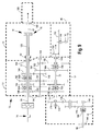
- Fig. 8 shows in a stick diagram an embodiment of a transmission 10 according to the invention, which is comparable to the in Fig. 1 and 2 shown gear is formed.
- the transmission 10 has a main transmission unit 12 with 9 forward and 3 reverse gears.
- the torque generated by the internal combustion engine 74 is first supplied via the drive shaft 84 to the coupling unit 16 of the option transmission module 14.
- the friction clutch unit 16 When the friction clutch unit 16 is engaged, the shift 118 of the crawler unit 18 is in the left engaged position, thus establishing a rotationally fixed connection between the output shaft 120 of the option transmission module 14 and the input shaft 52 of the main transmission unit 12, torque is applied to the main transmission unit 12 initiated.
- Both the output shaft 120 of the option transmission module 14 and the input shaft 52 of the main transmission unit 12 are formed as hollow shafts.
- the gear 122 is rotatably connected to the drive shaft 84 and meshes with both the input gear 124 of the two-stage gear unit 20 and the input gear 126 of the reversing unit 22.
- torque is transmitted from drive shaft 84 via option transmission module 14 to input shaft 52 of main transmission unit 12, optionally clutch unit 16, clutch unit 125 of two-stage transmission unit 20, or clutch unit 127 the reversing unit 22 is engaged, wherein always only one coupling unit 16, 125 or 127 can be engaged.
- the gear 136 is also rotatably connected to the output shaft 120 of the option transmission module 14 and meshes with the input gear 138 of the crawler unit 18.
- the gear 140 is rotatably connected, which meshes with the output gear 142 of the crawler unit 18. If the clutch unit 16 or the clutch unit 125 of the two-stage transmission unit 20 or the clutch unit 127 of the Reversiertechnik 22 is engaged and the switch 118 is in its right-hand engaged position, also a torque via the output shaft 120, the gear 136, the Input gear 138, the gear 140, the output gear 142 of the Kriechgang unit 18 and the switching point 118 transmitted to the input shaft 52 of the main transmission unit 12. Then the tractor 72 is in the crawl mode.
- Reference numeral 144 denotes the bearing points in the gear housing 11 or in the housing parts 24, 40, 42 and 44 of the individual shafts.
- the torque introduced into the main transmission unit 12 via the input shaft 52 is transmitted to the gear 146 if the shift point 68B is engaged. In this condition The first gear of the gearbox is engaged. The gear 146 meshes with the gear 148, which is rotatably connected to the intermediate shaft 54. If the switch 68B is not in the engaged position and the switch 68A is in the right-hand engaged position, the input shaft 52 is rotatably connected to the gear 150. In this state, the second gear is engaged the gearbox. The gear 150 meshes with the gear 152, which is also rotatably connected to the intermediate shaft 54 of the main transmission unit 12.
- the input shaft 52 is rotatably connected to the gear 154.
- the third gear of the gearbox is engaged.
- the gear 154 meshes with the gear 156, which is also rotatably connected to the intermediate shaft 54 of the main transmission unit 12.
- the gear 152 meshes the gear 158.
- the gears 160, 162 are rotatably connected to the intermediate shaft 54.
- the gear 166 meshes with the gear 164.
- the gear 162 meshes with the gear 166. Accordingly, the gears 158, 164, and 166 will rotate if the intermediate shaft 54 is rotated.
- the switch 70B is in the right-hand engaged position, a torque flow is established between the intermediate shaft 54 and the gears 162, 166 to the output shaft 56. In this state, the group A of the transmission 10 of the tractor 72 is inserted. If the switch 70B is in the left engaged position, there is a torque flow between the intermediate shaft 54 and the gears 160, 164 made to the output shaft 56.
- the group B of the transmission 10 of the tractor 72 is inserted. If the switch 70A is in the engaged position, a torque flow is established between the intermediate shaft 54 and the gears 152, 158 to the output shaft 56. In this state, the group C of the transmission 10 of the tractor 72 is inserted.
- the gear 170 of the differential gear 46 is rotated via the bevel gear 168, so that the output shaft 172 connected to the wheels 82A, 82B is also rotated and thus the tractor 72 is driven.
- the interface 48 is provided for the mechanical front-wheel drive.
- the gear 174 is rotatably connected, which meshes with the right gear of the double gear 176.
- the left gear of the double gear 176 meshes with the gear 178. If the shift 180 of the mechanical front-wheel drive interface 48 is in the engaged position, torque flow from the output shaft 56 of the main transmission unit 12 through the gears 174, 176 and 178 is to Drive shaft 98 for the wheels 80 A, 80 B of the front axle 76 made.
- the in Fig. 8 Gear shown 10 three gears and three groups with the main gear unit 12 provided there.
- the option transmission module 14 comprises, in addition to the coupling unit 16, the creeper unit 18, the two-stage transmission unit 20 and the reversing unit 22. Furthermore, the interface 48 for the front-wheel drive is attached to the transmission 10.
- Fig. 8a indicates one Fig. 8 modified embodiment of a transmission 10 according to the invention, wherein the change relates to the option transmission module 14.
- the option transmission module 14 a coupling unit 16, a two-stage gear unit 20 and a reversing unit 22 on.
- the gear 130 engaged with the hollow shaft 120 in rotation with the intermediate gear 132 meshes with the intermediate gear 132.
- the clutch unit 125 of the two-stage gear unit 20 and the clutch unit 16 are not engaged, the clutch unit 127 of the Reversiertechnik 22 is engaged, a torque from the drive shaft 84 transmitted via the reversing unit 22 to the hollow shaft 120 and thus to the main transmission unit 12.
- the functioning of the in Fig. 8a Otherwise, the transmission 10 shown is otherwise substantially similar to that of FIG Fig. 8 shown gear.
- Fig. 9 shows a further embodiment of a transmission 10 according to the invention, which has 12 forward and 4 reverse gears with three gears and four groups with the main gear unit 12 provided there.
- the option transmission module 14 includes in the in Fig. 9 shown gear 10 only the coupling unit 16 (ie the lowest stage of this embodiment), which can produce a torque flux of the drive shaft 84 via the output shaft 120 of the option transmission module 14 to the input shaft 52 of the main transmission unit 12 frictionally or force-locking.
- the shaft-hub connection 50 between option transmission module 14 and main transmission unit 12 is shown.
- main transmission unit 12 differs from that Fig. 8 essentially by the three links arranged on the left gear chains 182 to 194, which will be discussed in more detail below.
- the switch 68B now has two different positions, namely a right engaged position, which is substantially the same as in FIG Fig. 8 equivalent. This position corresponds to the second gear of the main transmission unit 12.
- a left engaged position in which a torque flow between the input shaft 52 of the main transmission unit 12 and the gear 182 can be made.
- the left engaged position of the shift point 68B corresponds to the third speed of the main transmission unit 12.
- the gear 182 meshes with the gear 184, which is non-rotatably connected to the intermediate shaft 54.
- the gear 184 meshes with the double gear 186 which is rotatably supported around the output shaft 56 of the main transmission unit 12. If the switch 68A is in the left-hand engaged position, a torque flow is established between the input shaft 52 of the main transmission unit 12 and the gear 188. The left engaged position of the shift point 68A corresponds to the first speed of the main transmission unit 12.
- the gear 188 meshes with the gear 190, which is non-rotatably connected to the intermediate shaft 54.
- the gear 190 meshes with the gear 192, which is rotatably supported around the output shaft 56 of the main transmission unit 12. If the switch 68A is in the right-hand engaged position, a torque flow is established between the input shaft 52 of the main transmission unit 12 and the gear 194.
- the right-hand engaged position of the shift point 68A corresponds to the reverse speed of the main transmission unit 12.
- the gear 194 meshes with the left-hand portion of the double-gear 186 indicated by the dashed line which is rotatably supported around the output shaft 56 of the main transmission unit 12.
- three forward gears and one reverse gear can be switched.
- the switching points 70A, 70B not only switch the in Fig. 8 3, groups A, B and C, but also a fourth group D, if the switch 70A is in the left-hand engaged position. Otherwise, the operation of the two switching points 70A, 70B and the transmission of the torque flow to the rear differential gear 46 and to the interface 48 for the mechanical front-wheel drive with that of Fig. 8 comparable.
- a series of transmissions in particular for an agricultural or industrial utility vehicle in the form of a tractor 72, thereby formed and advantageously can be represented economically by 12 different option gear modules 14 are adapted to each of a main gear unit.
- the main transmission unit 12 from Fig. 8 either with the option transmission module 14 off Fig. 8 or with the option transmission module 12 off Fig. 9 be combined.
- different transmissions 10 may be formed by the fact that the main transmission unit 12 is formed differently, wherein the transmission 10 may have the same or a different option transmission module 14.
- the main transmission unit 12 from Fig. 8 or the main transmission unit 12 Fig. 9 with the option transmission module 14 off Fig. 8 be combined.
- the main transmission unit 12 is, as a comparison between Fig. 8 and 9 shows, thereby differently formable that the input shaft 52, the intermediate shaft 54 and / or the output shaft 56 can be equipped with different gears.
- the corresponding switching devices 68A, 68B, 70A, 70B are arranged in each case in the same place or position in these embodiments.
- the bearing points 144 of the transmission shafts 52, 54 and 56 are arranged in these embodiments in differently configured main gear units 12 even with different equipping of the gear shafts 52, 54 and 56 of the main transmission unit 12 each at the same location or position.
- the same transmission housing 11 and the same switching devices 68A, 68B, 70A, 70B can always be used.
Landscapes
- Engineering & Computer Science (AREA)
- Mechanical Engineering (AREA)
- General Engineering & Computer Science (AREA)
- Chemical & Material Sciences (AREA)
- Combustion & Propulsion (AREA)
- Transportation (AREA)
- Arrangement Of Transmissions (AREA)
- Motor Power Transmission Devices (AREA)
Claims (15)
- Boîte de vitesses et module de boîte de vitesses optionnel pour transmettre un couple de rotation produit par un moteur d'entraînement en entrée à au moins un essieu d'entraînement en entrée d'un véhicule, notamment d'un véhicule utilitaire agricole ou industriel, avec au moins une unité de boîte de vitesses principale (12) opérationnelle en soi, l'unité de boîte de vitesses principale (12) comportant une boîte de vitesses à vitesses isolées et/ou une boîte de vitesses à vitesses groupées, un module de boîte de vitesses optionnel (14) disposé dans un carter de module de boîte de vitesses optionnel fermé pouvant être adapté à l'unité de boîte de vitesses principale (12) sous la forme d'une boîte de vitesses réalisée de façon autonome ou opérationnelle en soi et les fonctions de la boîte de vitesses (10) pouvant être élargies à l'aide du module de boîte de vitesses optionnel (14) et l'unité de boîte de vitesses principale (12) et le module de boîte de vitesses optionnel (14) étant réalisés de telle sorte que l'encombrement prévu ne change pour l'essentiel pas lorsque le module de boîte de vitesses optionnel (14) est adapté à l'unité de boîte de vitesses principale (12), caractérisée en ce que le module de boîte de vitesses optionnel (14) comporte une pompe à carburant propre et au moins un dispositif d'actionnement propre pour actionner les embrayages du module de boîte de vitesses optionnel (14) au moyen d'éléments de changement de vitesse hydrauliques.
- Boîte de vitesses selon la revendication 1, caractérisée en ce que le module de boîte de vitesses optionnel (14) comporte au moins une unité optionnelle, l'unité optionnelle prenant la forme d'au moins une unité d'embrayage (16) et/ou d'une unité inverseuse (22) et/ou d'une unité de vitesse extralente (18) et/ou d'une unité de boîte de vitesses à deux étages (20).
- Boîte de vitesses selon la revendication 1 ou 2, caractérisée en ce que le module de boîte de vitesses optionnel (14) comporte une partie de carter de base (24) à laquelle s'adapte l'au moins une unité optionnelle, notamment l'unité d'embrayage (16).
- Boîte de vitesses selon l'une quelconque des revendications 1 à 3, caractérisée par un carter de boîte de vitesses (11) réalisé à partir d'une ou de plusieurs pièces et recevant l'unité de boîte de vitesses principale (12), le carter de boîte de vitesses (11) étant réalisé de telle sorte que le module de boîte de vitesses optionnel (14) peut être monté au moins largement dans le carter de boîte de vitesses (11) et qu'un flux de couple de rotation peut être réalisé de façon directe ou indirecte entre le module de boîte de vitesses optionnel (14) et l'unité de boîte de vitesses principale (12).
- Boîte de vitesses selon l'une quelconque des revendications 1 à 4, caractérisée en ce que le module de boîte de vitesses optionnel (14) peut être adapté, à l'aide d'une liaison arbre-moyeu (50), à l'unité de boîte de vitesses principale (12), de préférence de façon réversible, la liaison arbre-moyeu (50) étant réalisée fixement sans couple de rotation par complémentarité de formes ou par complémentarité de frottements.
- Boîte de vitesses selon l'une quelconque des revendications 1 à 5, caractérisée en ce que l'unité de boîte de vitesses principale (12) prend la forme d'une boîte de vitesses à trois arbres et que les trois arbres de boîte de vitesses (52, 54, 56) sont disposés parallèlement les uns par rapport aux autres dans l'unité de boîte de vitesses principale (12).
- Boîte de vitesses selon l'une quelconque des revendications 1 à 6, caractérisée en ce qu'en cas d'attribution de propriétés différentes pour les différents arbres de boîte de vitesses (52, 54, 56) de l'unité de boîte de vitesses principale (12) prévue pour la boîte de vitesses (10), les dispositifs de changement de vitesses (68A, 68B, 70A, 70B) correspondants sont disposés respectivement à la même position et/ou qu'au moins un point d'appui (144) d'un arbre de boîte de vitesses (52, 54, 56) est disposé respectivement à la même position même en cas d'attribution différente des différentes propriétés d'une unité de boîte de vitesses principale (12) prévue pour la boîte de vitesses (10).
- Boîte de vitesses selon l'une quelconque des revendications 1 à 7, caractérisée en ce que l'unité de boîte de vitesses principale (12) comporte une ouverture de carter (34) servant pour le montage du module de boîte de vitesses optionnel (14), le module de boîte de vitesses optionnel (14) pouvant être amené dans l'ouverture de carter (34) pour le montage et l'ouverture de carter (34) étant de préférence réalisée en interaction avec le module de boîte de vitesses optionnel (14) de telle sorte que le module de boîte de vitesses optionnel (14) peut être déplacé, après avoir été placé dans un état amené dans l'ouverture de carter (34), dans au moins une direction relative par rapport à l'unité de boîte de vitesses principale (12) pour mettre en place une liaison arbre-moyeu (50) entre l'unité de boîte de vitesses principale (12) et le module de boîte de vitesses optionnel (14).
- Boîte de vitesses selon l'une quelconque des revendications 1 à 8, caractérisée en ce que l'unité de boîte de vitesses principale (12) comporte une interface mécanique supplémentaire, notamment une prise de force (108), pour transmettre le couple de rotation mécanique de l'unité de boîte de vitesses principale (12) et/ou du module de boîte de vitesses optionnel (14) et/ou du moteur d'entraînement en entrée (74) à un appareil de travail pouvant être adapté au véhicule (72).
- Boîte de vitesses selon l'une quelconque des revendications 1 à 9, caractérisée en ce que l'unité de boîte de vitesses principale (12) ou le module de boîte de vitesses optionnel (14) peut être relié au moteur d'entraînement en entrée (74) via un arbre de torsion (84) réalisé de préférence de telle sorte, par rapport à ses dimensions, qu'au moins une fréquence propre de l'ensemble de la boîte de vitesses (10), de préférence la première ou la plus basse, se situe en dehors de la plage de fréquence de la plage de nombres de tours utile.
- Boîte de vitesses selon l'une quelconque des revendications 1 à 10, caractérisée en ce que la boîte de vitesses à vitesses isolées ou la boîte de vitesses à vitesses groupées de l'unité de boîte de vitesses principale (12) prend la forme d'une boîte de vitesses commandée sous charge.
- Unité de boîte de vitesses principale pour un véhicule utilitaire agricole industriel, caractérisée par une configuration telle qu'un module de boîte de vitesses optionnel (14) selon l'une quelconque des revendications 1 à 11 peut être adapté à l'unité de boîte de vitesses principale (12).
- Module de boîte de vitesses optionnel pour une boîte de vitesses de véhicule utilitaire agricole ou industriel, caractérisé par une configuration telle que le module de boîte de vitesses optionnel (14) peut être adapté à une unité de boîte de vitesses principale (12) selon l'une quelconque des revendications 1 à 11.
- Véhicule utilitaire agricole ou industriel, notamment tracteur (72), caractérisé par une boîte de vitesses (10) selon l'une quelconque des revendications 1 à 11.
- Procédé de fabrication d'une boîte de vitesses selon l'une quelconque des revendications 1 à 11, caractérisé en ce que le module de boîte de vitesses optionnel (14) peut être monté de telle sorte à l'unité de boîte de vitesses principale (12) de la boîte de vitesses (10) que le module de boîte de vitesses optionnel (14) peut être amené dans une ouverture de carter (34) du carter de boîte de vitesses (11) de l'unité de boîte de vitesses principale (12), que le module de boîte de vitesses optionnel (14) peut être déplacé de telle sorte le long d'au moins une direction qu'une liaison arbre-moyeu (50) est établie entre le module de boîte de vitesses optionnel (14) et l'unité de boîte de vitesses principale (12) et que le module de boîte de vitesses optionnel (14) est fixé à l'unité de boîte de vitesses principale (12), de préférence au carter (11) de l'unité de boîte de vitesses principale (12).
Applications Claiming Priority (2)
| Application Number | Priority Date | Filing Date | Title |
|---|---|---|---|
| DE102007003340A DE102007003340A1 (de) | 2007-01-17 | 2007-01-17 | Getriebe |
| PCT/EP2008/050485 WO2008087176A1 (fr) | 2007-01-17 | 2008-01-17 | Engrenage |
Publications (2)
| Publication Number | Publication Date |
|---|---|
| EP2122200A1 EP2122200A1 (fr) | 2009-11-25 |
| EP2122200B1 true EP2122200B1 (fr) | 2011-10-12 |
Family
ID=39267864
Family Applications (1)
| Application Number | Title | Priority Date | Filing Date |
|---|---|---|---|
| EP08701546A Active EP2122200B1 (fr) | 2007-01-17 | 2008-01-17 | Engrenage |
Country Status (8)
| Country | Link |
|---|---|
| US (1) | US20100107812A1 (fr) |
| EP (1) | EP2122200B1 (fr) |
| JP (1) | JP2010516956A (fr) |
| KR (1) | KR20090108600A (fr) |
| AT (1) | ATE528546T1 (fr) |
| BR (1) | BRPI0806258A2 (fr) |
| DE (1) | DE102007003340A1 (fr) |
| WO (1) | WO2008087176A1 (fr) |
Families Citing this family (7)
| Publication number | Priority date | Publication date | Assignee | Title |
|---|---|---|---|---|
| DE102012002798A1 (de) * | 2012-02-15 | 2013-08-22 | Claas Tractor S.A.S. | Traktor mit Zapfwellenausgang |
| DE102013222500A1 (de) * | 2013-11-06 | 2015-05-07 | Zf Friedrichshafen Ag | Antriebsstrang für ein Kraftfahrzeug |
| US9488263B2 (en) | 2014-08-15 | 2016-11-08 | Caterpillar Inc. | Modular arrangement for hydromechanical transmission |
| EP3798468A3 (fr) * | 2019-09-26 | 2021-10-06 | Kubota Corporation | Dispositif de transmission d'entraînement de tracteur |
| US11613177B2 (en) * | 2020-10-28 | 2023-03-28 | Deere & Company | Drop-box transmission in a reduced space |
| DE102020134114A1 (de) * | 2020-12-18 | 2022-06-23 | Deere & Company | Getriebe und landwirtschaftliches oder industrielles Nutzfahrzeug |
| DE102021209464A1 (de) * | 2021-08-30 | 2023-03-02 | Zf Friedrichshafen Ag | Leistungsstranganordnung einer Arbeitsmaschine und Arbeitsmaschine |
Family Cites Families (30)
| Publication number | Priority date | Publication date | Assignee | Title |
|---|---|---|---|---|
| FR1454031A (fr) * | 1965-08-19 | 1966-07-22 | Boîte de vitesses | |
| DE2715874C3 (de) * | 1977-04-09 | 1981-04-30 | Gerold Ing.(grad.) 7994 Langenargen Bieber | Zahnräder-Wechselgetriebe |
| JPS55111821U (fr) * | 1979-02-02 | 1980-08-06 | ||
| US4388843A (en) * | 1980-11-21 | 1983-06-21 | Eaton Corporation | Auxiliary transmission neutral positioning and locking control and mechanism |
| DE3137805A1 (de) * | 1981-09-23 | 1983-03-31 | Deere & Co., 61265 Moline, Ill. | Getriebe zum querstehenden einbau und motorfahrzeug mit eingebautem getriebe |
| US4528867A (en) * | 1982-09-13 | 1985-07-16 | Iseki & Co., Ltd. | Transmission case for tractors |
| US4658662A (en) * | 1984-04-16 | 1987-04-21 | Rundle Kenneth P | Transmission and PTO system for tractors and utility cycles |
| AU572741B2 (en) * | 1986-03-03 | 1988-05-12 | Kubota Ltd. | Transmission for working vehicle with an overtop drive |
| JPS6322229U (fr) * | 1986-07-30 | 1988-02-13 | ||
| DE3633372A1 (de) * | 1986-10-01 | 1988-04-14 | Deere & Co | Verfahren zum schalten eines aus mehreren getriebeeinheiten bestehenden getriebes |
| US4858495A (en) * | 1988-06-08 | 1989-08-22 | J. I. Case Company | Multi-speed powershift transmission |
| US4877116A (en) * | 1988-06-30 | 1989-10-31 | J. I. Case Company | Hydraulic control system for a tractor transmission |
| EP0480955B1 (fr) * | 1989-07-05 | 1994-11-02 | ZF FRIEDRICHSHAFEN Aktiengesellschaft | Boite de vitesses a pignons et a etages multiples |
| JPH04171346A (ja) * | 1990-10-30 | 1992-06-18 | Iseki & Co Ltd | トラクタのクラッチハウジング |
| US5178039A (en) * | 1992-01-22 | 1993-01-12 | Deere & Company | Modular transmission |
| US5404772A (en) * | 1992-11-06 | 1995-04-11 | Dana Corporation | Transmission housing |
| JP2556205Y2 (ja) * | 1992-12-18 | 1997-12-03 | 株式会社 神崎高級工機製作所 | 作業車両のミッション装置 |
| US6119552A (en) * | 1997-09-01 | 2000-09-19 | Kanzaki Kokyukoki Mfg. Co., Ltd. | Transmission for a working vehicle |
| JP4043096B2 (ja) * | 1998-04-13 | 2008-02-06 | 株式会社 神崎高級工機製作所 | 作業車両用の走行駆動トランスミッション |
| DE19837776A1 (de) * | 1998-08-20 | 2000-02-24 | Zahnradfabrik Friedrichshafen | Getriebe mit nicht-koaxialem Abtrieb |
| JP4201228B2 (ja) * | 1999-06-14 | 2008-12-24 | 株式会社 神崎高級工機製作所 | 作業車両のトランスミッション |
| JP4439037B2 (ja) * | 1999-06-14 | 2010-03-24 | 株式会社 神崎高級工機製作所 | 作業車両における変速装置 |
| JP2001287565A (ja) * | 2000-04-10 | 2001-10-16 | Kanzaki Kokyukoki Mfg Co Ltd | トラクタの変速操作装置 |
| JP4162359B2 (ja) * | 2000-05-09 | 2008-10-08 | 株式会社Ihiシバウラ | 油圧・機械式無段変速装置 |
| DE10123194A1 (de) * | 2001-05-12 | 2002-11-21 | Voith Turbo Kg | Plattformgetriebe und Getriebebaukasten |
| US6889569B2 (en) * | 2001-08-09 | 2005-05-10 | Kubota Corporation | Change speed apparatus for a working vehicle that engages in an operation while moving forward and backward |
| DE10228501B4 (de) * | 2002-06-21 | 2008-10-16 | Getrag Innovations Gmbh | Automatisches Wechselgetriebe |
| SE526423C2 (sv) * | 2003-02-25 | 2005-09-13 | Vce Holding Sweden Ab | Motorfordonsväxellåda |
| DE10324095A1 (de) * | 2003-05-27 | 2004-12-16 | Deere & Company, Moline | Getriebeanordnung und Verfahren zum Betreiben einer Getriebeanordnung |
| JP4384457B2 (ja) * | 2003-09-09 | 2009-12-16 | 本田技研工業株式会社 | エンジン |
-
2007
- 2007-01-17 DE DE102007003340A patent/DE102007003340A1/de not_active Withdrawn
-
2008
- 2008-01-17 WO PCT/EP2008/050485 patent/WO2008087176A1/fr active Application Filing
- 2008-01-17 US US12/523,547 patent/US20100107812A1/en not_active Abandoned
- 2008-01-17 BR BRPI0806258-7A patent/BRPI0806258A2/pt not_active IP Right Cessation
- 2008-01-17 JP JP2009545923A patent/JP2010516956A/ja active Pending
- 2008-01-17 AT AT08701546T patent/ATE528546T1/de active
- 2008-01-17 EP EP08701546A patent/EP2122200B1/fr active Active
- 2008-01-17 KR KR1020097014997A patent/KR20090108600A/ko not_active Application Discontinuation
Also Published As
| Publication number | Publication date |
|---|---|
| DE102007003340A1 (de) | 2008-07-24 |
| JP2010516956A (ja) | 2010-05-20 |
| KR20090108600A (ko) | 2009-10-15 |
| ATE528546T1 (de) | 2011-10-15 |
| EP2122200A1 (fr) | 2009-11-25 |
| WO2008087176A1 (fr) | 2008-07-24 |
| BRPI0806258A2 (pt) | 2011-08-30 |
| US20100107812A1 (en) | 2010-05-06 |
Similar Documents
| Publication | Publication Date | Title |
|---|---|---|
| EP2577097B1 (fr) | Système de transmission | |
| DE102004022413B4 (de) | Doppelkupplungsgetriebe | |
| EP2122200B1 (fr) | Engrenage | |
| EP0481014B1 (fr) | Boite de vitesse a engrenages a etages multiples | |
| DE3137805A1 (de) | Getriebe zum querstehenden einbau und motorfahrzeug mit eingebautem getriebe | |
| WO1997001049A1 (fr) | Transmission a derivation de puissance hydrostatique--mecanique | |
| DE102019204909A1 (de) | Getriebe, Getriebebaugruppe und Antriebsstrang | |
| EP0552673B1 (fr) | Boîte de vitesse pour véhicule à moteur | |
| WO2005003593A1 (fr) | Boite de vitesses couplable sous charge pour engins de chantier, en particulier pour chargeuses-pelleteuses et manipulateurs telescopiques | |
| WO2014154418A1 (fr) | Boîte de vitesses destinée à un véhicule automobile | |
| DE102012208161A1 (de) | Getriebe, insbesondere automatisiertes Schaltgetriebe, sowie Verwendung einer Viergang-Schaltgruppe und Kraftfahrzeug | |
| DE2110434B2 (de) | Zahnräderwechselgetriebe in Gruppenbauart für Kraftfahrzeuge mit einem Zentralrohrrahmen und insbesondere mit einem Mehrachsantrieb | |
| DE4020959A1 (de) | Vielstufiges zahnraederwechselgetriebe | |
| EP2098432A1 (fr) | Transmission pour un véhicule automobile doté de deux directions de circulation équivalentes | |
| DE102014220028B4 (de) | Getriebevorrichtung mit Leistungsverzweigung | |
| EP2084430B1 (fr) | Transmission d'un véhicule pouvant être entraîné par un moteur | |
| DE102019207925A1 (de) | Nebenabtriebsgetriebe und landwirtschaftliche Arbeitsmaschine | |
| DE102006022183B4 (de) | Doppelkupplungsgetriebe | |
| DE4127609A1 (de) | Zahnraederwechselgetriebe in vorgelegebauweise fuer ein kraftfahrzeug | |
| WO1992004561A1 (fr) | Boite de vitesses a engrenages a etages multiples | |
| DE102005006727B4 (de) | Winkelgetriebe für einen Antriebsstrang | |
| EP3961064A1 (fr) | Transmission, syst?me de transmission et véhicule tracteur agricole | |
| WO2022048947A1 (fr) | Unité de transmission, agencement de transmission et véhicule tracteur agricole | |
| DE102020122827A1 (de) | Getriebeeinheit, Getriebeanordnung und landwirtschaftliches Zugfahrzeug | |
| DE10250970A1 (de) | Getriebe für ein Kraftfahrzeug |
Legal Events
| Date | Code | Title | Description |
|---|---|---|---|
| PUAI | Public reference made under article 153(3) epc to a published international application that has entered the european phase |
Free format text: ORIGINAL CODE: 0009012 |
|
| 17P | Request for examination filed |
Effective date: 20090817 |
|
| AK | Designated contracting states |
Kind code of ref document: A1 Designated state(s): AT BE BG CH CY CZ DE DK EE ES FI FR GB GR HR HU IE IS IT LI LT LU LV MC MT NL NO PL PT RO SE SI SK TR |
|
| DAX | Request for extension of the european patent (deleted) | ||
| 17Q | First examination report despatched |
Effective date: 20100316 |
|
| GRAP | Despatch of communication of intention to grant a patent |
Free format text: ORIGINAL CODE: EPIDOSNIGR1 |
|
| GRAS | Grant fee paid |
Free format text: ORIGINAL CODE: EPIDOSNIGR3 |
|
| GRAA | (expected) grant |
Free format text: ORIGINAL CODE: 0009210 |
|
| AK | Designated contracting states |
Kind code of ref document: B1 Designated state(s): AT BE BG CH CY CZ DE DK EE ES FI FR GB GR HR HU IE IS IT LI LT LU LV MC MT NL NO PL PT RO SE SI SK TR |
|
| REG | Reference to a national code |
Ref country code: GB Ref legal event code: FG4D Free format text: NOT ENGLISH |
|
| REG | Reference to a national code |
Ref country code: CH Ref legal event code: EP |
|
| REG | Reference to a national code |
Ref country code: IE Ref legal event code: FG4D |
|
| REG | Reference to a national code |
Ref country code: DE Ref legal event code: R096 Ref document number: 502008005155 Country of ref document: DE Effective date: 20111208 |
|
| REG | Reference to a national code |
Ref country code: NL Ref legal event code: VDEP Effective date: 20111012 |
|
| LTIE | Lt: invalidation of european patent or patent extension |
Effective date: 20111012 |
|
| PG25 | Lapsed in a contracting state [announced via postgrant information from national office to epo] |
Ref country code: LT Free format text: LAPSE BECAUSE OF FAILURE TO SUBMIT A TRANSLATION OF THE DESCRIPTION OR TO PAY THE FEE WITHIN THE PRESCRIBED TIME-LIMIT Effective date: 20111012 Ref country code: NO Free format text: LAPSE BECAUSE OF FAILURE TO SUBMIT A TRANSLATION OF THE DESCRIPTION OR TO PAY THE FEE WITHIN THE PRESCRIBED TIME-LIMIT Effective date: 20120112 Ref country code: IS Free format text: LAPSE BECAUSE OF FAILURE TO SUBMIT A TRANSLATION OF THE DESCRIPTION OR TO PAY THE FEE WITHIN THE PRESCRIBED TIME-LIMIT Effective date: 20120212 |
|
| REG | Reference to a national code |
Ref country code: IE Ref legal event code: FD4D |
|
| PG25 | Lapsed in a contracting state [announced via postgrant information from national office to epo] |
Ref country code: PT Free format text: LAPSE BECAUSE OF FAILURE TO SUBMIT A TRANSLATION OF THE DESCRIPTION OR TO PAY THE FEE WITHIN THE PRESCRIBED TIME-LIMIT Effective date: 20120213 Ref country code: NL Free format text: LAPSE BECAUSE OF FAILURE TO SUBMIT A TRANSLATION OF THE DESCRIPTION OR TO PAY THE FEE WITHIN THE PRESCRIBED TIME-LIMIT Effective date: 20111012 Ref country code: GR Free format text: LAPSE BECAUSE OF FAILURE TO SUBMIT A TRANSLATION OF THE DESCRIPTION OR TO PAY THE FEE WITHIN THE PRESCRIBED TIME-LIMIT Effective date: 20120113 Ref country code: LV Free format text: LAPSE BECAUSE OF FAILURE TO SUBMIT A TRANSLATION OF THE DESCRIPTION OR TO PAY THE FEE WITHIN THE PRESCRIBED TIME-LIMIT Effective date: 20111012 Ref country code: SI Free format text: LAPSE BECAUSE OF FAILURE TO SUBMIT A TRANSLATION OF THE DESCRIPTION OR TO PAY THE FEE WITHIN THE PRESCRIBED TIME-LIMIT Effective date: 20111012 Ref country code: HR Free format text: LAPSE BECAUSE OF FAILURE TO SUBMIT A TRANSLATION OF THE DESCRIPTION OR TO PAY THE FEE WITHIN THE PRESCRIBED TIME-LIMIT Effective date: 20111012 Ref country code: SE Free format text: LAPSE BECAUSE OF FAILURE TO SUBMIT A TRANSLATION OF THE DESCRIPTION OR TO PAY THE FEE WITHIN THE PRESCRIBED TIME-LIMIT Effective date: 20111012 |
|
| PG25 | Lapsed in a contracting state [announced via postgrant information from national office to epo] |
Ref country code: CY Free format text: LAPSE BECAUSE OF FAILURE TO SUBMIT A TRANSLATION OF THE DESCRIPTION OR TO PAY THE FEE WITHIN THE PRESCRIBED TIME-LIMIT Effective date: 20111012 |
|
| BERE | Be: lapsed |
Owner name: DEERE & CY Effective date: 20120131 |
|
| PG25 | Lapsed in a contracting state [announced via postgrant information from national office to epo] |
Ref country code: DK Free format text: LAPSE BECAUSE OF FAILURE TO SUBMIT A TRANSLATION OF THE DESCRIPTION OR TO PAY THE FEE WITHIN THE PRESCRIBED TIME-LIMIT Effective date: 20111012 Ref country code: BG Free format text: LAPSE BECAUSE OF FAILURE TO SUBMIT A TRANSLATION OF THE DESCRIPTION OR TO PAY THE FEE WITHIN THE PRESCRIBED TIME-LIMIT Effective date: 20120112 Ref country code: IE Free format text: LAPSE BECAUSE OF FAILURE TO SUBMIT A TRANSLATION OF THE DESCRIPTION OR TO PAY THE FEE WITHIN THE PRESCRIBED TIME-LIMIT Effective date: 20111012 Ref country code: EE Free format text: LAPSE BECAUSE OF FAILURE TO SUBMIT A TRANSLATION OF THE DESCRIPTION OR TO PAY THE FEE WITHIN THE PRESCRIBED TIME-LIMIT Effective date: 20111012 Ref country code: SK Free format text: LAPSE BECAUSE OF FAILURE TO SUBMIT A TRANSLATION OF THE DESCRIPTION OR TO PAY THE FEE WITHIN THE PRESCRIBED TIME-LIMIT Effective date: 20111012 |
|
| PLBE | No opposition filed within time limit |
Free format text: ORIGINAL CODE: 0009261 |
|
| STAA | Information on the status of an ep patent application or granted ep patent |
Free format text: STATUS: NO OPPOSITION FILED WITHIN TIME LIMIT |
|
| PG25 | Lapsed in a contracting state [announced via postgrant information from national office to epo] |
Ref country code: PL Free format text: LAPSE BECAUSE OF FAILURE TO SUBMIT A TRANSLATION OF THE DESCRIPTION OR TO PAY THE FEE WITHIN THE PRESCRIBED TIME-LIMIT Effective date: 20111012 Ref country code: MC Free format text: LAPSE BECAUSE OF NON-PAYMENT OF DUE FEES Effective date: 20120131 Ref country code: RO Free format text: LAPSE BECAUSE OF FAILURE TO SUBMIT A TRANSLATION OF THE DESCRIPTION OR TO PAY THE FEE WITHIN THE PRESCRIBED TIME-LIMIT Effective date: 20111012 |
|
| REG | Reference to a national code |
Ref country code: CH Ref legal event code: PL |
|
| 26N | No opposition filed |
Effective date: 20120713 |
|
| PG25 | Lapsed in a contracting state [announced via postgrant information from national office to epo] |
Ref country code: LI Free format text: LAPSE BECAUSE OF NON-PAYMENT OF DUE FEES Effective date: 20120131 Ref country code: CH Free format text: LAPSE BECAUSE OF NON-PAYMENT OF DUE FEES Effective date: 20120131 |
|
| REG | Reference to a national code |
Ref country code: DE Ref legal event code: R097 Ref document number: 502008005155 Country of ref document: DE Effective date: 20120713 |
|
| PG25 | Lapsed in a contracting state [announced via postgrant information from national office to epo] |
Ref country code: BE Free format text: LAPSE BECAUSE OF NON-PAYMENT OF DUE FEES Effective date: 20120131 |
|
| PG25 | Lapsed in a contracting state [announced via postgrant information from national office to epo] |
Ref country code: ES Free format text: LAPSE BECAUSE OF FAILURE TO SUBMIT A TRANSLATION OF THE DESCRIPTION OR TO PAY THE FEE WITHIN THE PRESCRIBED TIME-LIMIT Effective date: 20120123 |
|
| PG25 | Lapsed in a contracting state [announced via postgrant information from national office to epo] |
Ref country code: FI Free format text: LAPSE BECAUSE OF FAILURE TO SUBMIT A TRANSLATION OF THE DESCRIPTION OR TO PAY THE FEE WITHIN THE PRESCRIBED TIME-LIMIT Effective date: 20111012 |
|
| PG25 | Lapsed in a contracting state [announced via postgrant information from national office to epo] |
Ref country code: MT Free format text: LAPSE BECAUSE OF FAILURE TO SUBMIT A TRANSLATION OF THE DESCRIPTION OR TO PAY THE FEE WITHIN THE PRESCRIBED TIME-LIMIT Effective date: 20111012 |
|
| REG | Reference to a national code |
Ref country code: AT Ref legal event code: MM01 Ref document number: 528546 Country of ref document: AT Kind code of ref document: T Effective date: 20130117 |
|
| PG25 | Lapsed in a contracting state [announced via postgrant information from national office to epo] |
Ref country code: TR Free format text: LAPSE BECAUSE OF FAILURE TO SUBMIT A TRANSLATION OF THE DESCRIPTION OR TO PAY THE FEE WITHIN THE PRESCRIBED TIME-LIMIT Effective date: 20111012 |
|
| PG25 | Lapsed in a contracting state [announced via postgrant information from national office to epo] |
Ref country code: LU Free format text: LAPSE BECAUSE OF NON-PAYMENT OF DUE FEES Effective date: 20120117 Ref country code: AT Free format text: LAPSE BECAUSE OF NON-PAYMENT OF DUE FEES Effective date: 20130117 |
|
| PGFP | Annual fee paid to national office [announced via postgrant information from national office to epo] |
Ref country code: FR Payment date: 20140117 Year of fee payment: 7 Ref country code: IT Payment date: 20140122 Year of fee payment: 7 |
|
| PGFP | Annual fee paid to national office [announced via postgrant information from national office to epo] |
Ref country code: GB Payment date: 20140127 Year of fee payment: 7 |
|
| PG25 | Lapsed in a contracting state [announced via postgrant information from national office to epo] |
Ref country code: HU Free format text: LAPSE BECAUSE OF FAILURE TO SUBMIT A TRANSLATION OF THE DESCRIPTION OR TO PAY THE FEE WITHIN THE PRESCRIBED TIME-LIMIT Effective date: 20080117 |
|
| PGFP | Annual fee paid to national office [announced via postgrant information from national office to epo] |
Ref country code: CZ Payment date: 20150109 Year of fee payment: 8 |
|
| GBPC | Gb: european patent ceased through non-payment of renewal fee |
Effective date: 20150117 |
|
| PG25 | Lapsed in a contracting state [announced via postgrant information from national office to epo] |
Ref country code: GB Free format text: LAPSE BECAUSE OF NON-PAYMENT OF DUE FEES Effective date: 20150117 |
|
| REG | Reference to a national code |
Ref country code: FR Ref legal event code: ST Effective date: 20150930 |
|
| PG25 | Lapsed in a contracting state [announced via postgrant information from national office to epo] |
Ref country code: FR Free format text: LAPSE BECAUSE OF NON-PAYMENT OF DUE FEES Effective date: 20150202 |
|
| PG25 | Lapsed in a contracting state [announced via postgrant information from national office to epo] |
Ref country code: IT Free format text: LAPSE BECAUSE OF NON-PAYMENT OF DUE FEES Effective date: 20150117 |
|
| PG25 | Lapsed in a contracting state [announced via postgrant information from national office to epo] |
Ref country code: CZ Free format text: LAPSE BECAUSE OF NON-PAYMENT OF DUE FEES Effective date: 20160117 |
|
| PGFP | Annual fee paid to national office [announced via postgrant information from national office to epo] |
Ref country code: DE Payment date: 20231220 Year of fee payment: 17 |