EP2122128B1 - Roue de turbine - Google Patents
Roue de turbine Download PDFInfo
- Publication number
- EP2122128B1 EP2122128B1 EP08709169A EP08709169A EP2122128B1 EP 2122128 B1 EP2122128 B1 EP 2122128B1 EP 08709169 A EP08709169 A EP 08709169A EP 08709169 A EP08709169 A EP 08709169A EP 2122128 B1 EP2122128 B1 EP 2122128B1
- Authority
- EP
- European Patent Office
- Prior art keywords
- shroud
- region
- moving blades
- gap
- circumferential direction
- Prior art date
- Legal status (The legal status is an assumption and is not a legal conclusion. Google has not performed a legal analysis and makes no representation as to the accuracy of the status listed.)
- Active
Links
- 230000007704 transition Effects 0.000 claims abstract description 14
- 238000005266 casting Methods 0.000 description 6
- 230000006870 function Effects 0.000 description 5
- 239000007789 gas Substances 0.000 description 5
- 238000004519 manufacturing process Methods 0.000 description 4
- 230000009467 reduction Effects 0.000 description 3
- 230000005540 biological transmission Effects 0.000 description 2
- 238000000227 grinding Methods 0.000 description 2
- 238000002485 combustion reaction Methods 0.000 description 1
- 238000013016 damping Methods 0.000 description 1
- 230000001419 dependent effect Effects 0.000 description 1
- 230000000694 effects Effects 0.000 description 1
- 238000000034 method Methods 0.000 description 1
- 238000003801 milling Methods 0.000 description 1
- 238000000465 moulding Methods 0.000 description 1
- 238000005457 optimization Methods 0.000 description 1
- 238000012805 post-processing Methods 0.000 description 1
- 230000008569 process Effects 0.000 description 1
- 238000012545 processing Methods 0.000 description 1
- 238000007493 shaping process Methods 0.000 description 1
Images


Classifications
-
- F—MECHANICAL ENGINEERING; LIGHTING; HEATING; WEAPONS; BLASTING
- F01—MACHINES OR ENGINES IN GENERAL; ENGINE PLANTS IN GENERAL; STEAM ENGINES
- F01D—NON-POSITIVE DISPLACEMENT MACHINES OR ENGINES, e.g. STEAM TURBINES
- F01D5/00—Blades; Blade-carrying members; Heating, heat-insulating, cooling or antivibration means on the blades or the members
- F01D5/12—Blades
- F01D5/22—Blade-to-blade connections, e.g. for damping vibrations
- F01D5/225—Blade-to-blade connections, e.g. for damping vibrations by shrouding
-
- F—MECHANICAL ENGINEERING; LIGHTING; HEATING; WEAPONS; BLASTING
- F01—MACHINES OR ENGINES IN GENERAL; ENGINE PLANTS IN GENERAL; STEAM ENGINES
- F01D—NON-POSITIVE DISPLACEMENT MACHINES OR ENGINES, e.g. STEAM TURBINES
- F01D5/00—Blades; Blade-carrying members; Heating, heat-insulating, cooling or antivibration means on the blades or the members
- F01D5/12—Blades
- F01D5/22—Blade-to-blade connections, e.g. for damping vibrations
-
- F—MECHANICAL ENGINEERING; LIGHTING; HEATING; WEAPONS; BLASTING
- F01—MACHINES OR ENGINES IN GENERAL; ENGINE PLANTS IN GENERAL; STEAM ENGINES
- F01D—NON-POSITIVE DISPLACEMENT MACHINES OR ENGINES, e.g. STEAM TURBINES
- F01D7/00—Rotors with blades adjustable in operation; Control thereof
-
- F—MECHANICAL ENGINEERING; LIGHTING; HEATING; WEAPONS; BLASTING
- F02—COMBUSTION ENGINES; HOT-GAS OR COMBUSTION-PRODUCT ENGINE PLANTS
- F02B—INTERNAL-COMBUSTION PISTON ENGINES; COMBUSTION ENGINES IN GENERAL
- F02B39/00—Component parts, details, or accessories relating to, driven charging or scavenging pumps, not provided for in groups F02B33/00 - F02B37/00
-
- F—MECHANICAL ENGINEERING; LIGHTING; HEATING; WEAPONS; BLASTING
- F02—COMBUSTION ENGINES; HOT-GAS OR COMBUSTION-PRODUCT ENGINE PLANTS
- F02C—GAS-TURBINE PLANTS; AIR INTAKES FOR JET-PROPULSION PLANTS; CONTROLLING FUEL SUPPLY IN AIR-BREATHING JET-PROPULSION PLANTS
- F02C6/00—Plural gas-turbine plants; Combinations of gas-turbine plants with other apparatus; Adaptations of gas-turbine plants for special use
- F02C6/04—Gas-turbine plants providing heated or pressurised working fluid for other apparatus, e.g. without mechanical power output
- F02C6/10—Gas-turbine plants providing heated or pressurised working fluid for other apparatus, e.g. without mechanical power output supplying working fluid to a user, e.g. a chemical process, which returns working fluid to a turbine of the plant
- F02C6/12—Turbochargers, i.e. plants for augmenting mechanical power output of internal-combustion piston engines by increase of charge pressure
Definitions
- the invention relates to the field of turbomachines, in particular exhaust gas turbocharger for supercharged internal combustion engines.
- It relates to a turbine wheel with a plurality of blades, which each have at their free ends shroud segments.
- Axial turbines thermal turbomachines such as gas turbines or turbines exhaust gas turbochargers, have a plurality of blades, which are arranged on a hub which is rotatably mounted about a shaft.
- the blades often have at their radially outer, free ends shrouds - in technical language called "Shroud" - on.
- a shroud is composed of individual segments, which are integrally connected to one blade.
- the segments are braced against each other by a torsional bias of the blades during assembly or in operation by the natural unwinding of the blades under the influence of centrifugal force.
- the function of the shrouds is to improve the thermodynamic efficiency by minimizing the gap losses, as well as in the optimization of the vibration behavior by their damping and stiffening effect.
- FIG US 5,593,282 An exemplary form of transition between the shroud segments of adjacently disposed gas turbine rotor blades is in FIG US 5,593,282 .
- Fig. 4 displayed.
- EP 1 724 441 there is disclosed a junction between the shroud segments of adjacently disposed blades of a turbine wheel which is divided into a contact region and a gap region, wherein the contact region and gap region are disposed radially at a height.
- the object of the present invention is to design the transition between the shroud segments adjacent turbine blades arranged so that the requirements in terms of thermodynamics, durability, surface pressure, assembly and manufacturing can be met.
- the transition between the shroud segments adjacent arranged blades of a turbine wheel is divided into two areas, a simple, inexpensive to be processed contact area and a - arbitrarily complicated - cast residual area.
- the shroud is in the radial direction, so seen over the blade height, divided into two levels.
- the radially outer, upper plane assumes the function of the mechanical bond between the blades in the contact area.
- the shroud segments of the adjacent blades are in contact in this area.
- the lower level of the shroud takes over the function of the flow guide, in particular the reduction of overflows on the blade tip.
- the shroud seen in the flow direction is advantageously wider than in the contact area.
- the transition to the adjacently located blades in this plane is generally oriented differently than in the contact region for flow and mountability considerations. Since no frictional connection is required in this plane, the shaping of the surface of the shroud segments are realized by casting. To compensate for the casting tolerances of this contact area can be designed as a clearance.
- the power transmission takes place between the blade ends.
- the remaining region of the transition has a gap between the shroud segments of the respective rotor blades arranged adjacent to one another so that contact between the rotor blades does not occur in this region.
- the contact area is provided with a simple surface geometry, so that it is easy to machine mechanically.
- the transition in the region of the gap, can have a more complex, in particular non-linear, surface profile, which is advantageously already formed in the casting mold during the production of the cast blank of the rotor blades.
- the inner area of the shroud which is not required for the contacting, does not contribute to the transmission of force between the shroud segments of the rotor blades. Its function consists essentially in the reduction of thermodynamic losses due to overflow of the blade tip.
- the angular position of the surface in the contact region is essentially determined by boundary conditions of the mechanics and the mountability.
- the contact surfaces must be machined due to the high dimensional stability requirements, e.g. be sanded. For cost-effective processing, they can be executed as flat surfaces.
- Fig. 1 shows a portion of the blades 10 of an axial turbine of a turbocharger.
- the blades are arranged with blade roots 14 in a blade carrier, the hub of the turbine wheel.
- the hub of the turbine wheel is rotatably mounted on a shaft about an axis.
- the terms “radial”, “axial” and “circumferentially” used here refer to this axis.
- the blade roots are formed fir tree-shaped and inserted in the axial direction in the same shape shaped grooves and secured axially.
- the blades have an aerodynamically shaped blade body 11, which is the flow, so the hot exhaust gases, exposed.
- the rotor blades At their radially outer, free ends, the rotor blades have a shroud which projects at least in sections over the blade body in the axial direction.
- the shroud is divided into many short segments 12 which are each integrally connected to a blade.
- the shroud of the rotor blades designed according to the invention has, radially outside the segments extending in the axial direction, a second, axially shorter region 13, which serves to connect the individual rotor blades to one another.
- the function of the radially inner shroud region lies essentially in the reduction of the thermodynamic losses due to overflow of the blade tip.
- a gap 19 is present in the radially inner region of the shroud segments 12 between in each case two shroud segments arranged adjacent to one another.
- the radially outer shroud segments as is out Fig. 2 can be seen, pressed together seamlessly.
- the transitions of the shroud segments are thus subdivided into a contact region and a gap region.
- each shroud segment-in the circumferential direction at both ends- has an easily machinable contact surface 15.
- This is advantageously a single, flat surface or then it is composed of a few, flat surfaces. Thanks to its simple geometric shape, the contact area of each blade can be machined in a simple way, for example by grinding or milling.
- the surface 16 may have an arbitrarily complex shape, so that, for example, a fluidically optimized transition can be formed.
- This area of the transition can already be made when casting the blade in its final form.
- the molding during casting is considerably less expensive than the subsequent mechanical creation of the complex transitional area. Thanks to the existing gap, the deviations from the intended surface course that result in the case of complex casting molds can be tolerated, so that, as a rule, post-processing of this area can be completely dispensed with.
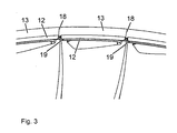
- Fig. 3 shows the group of blades in the axial direction. Clearly, the gap 19 between the axially protruding shroud segments 12 can be seen.
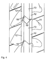
- Fig. 4 shows the blades and the shroud viewed from radially outside to inside. Again, the gap 19 between the axially outer shroud segments 12 can be seen, as well as the circumferentially closely pressed together inner portions 13 of the shroud.
Landscapes
- Engineering & Computer Science (AREA)
- Mechanical Engineering (AREA)
- General Engineering & Computer Science (AREA)
- Chemical & Material Sciences (AREA)
- Combustion & Propulsion (AREA)
- Chemical Kinetics & Catalysis (AREA)
- General Chemical & Material Sciences (AREA)
- Supercharger (AREA)
- Turbine Rotor Nozzle Sealing (AREA)
Claims (5)
- Roue de turbine, comprenant une multiplicité d'aubes mobiles (10), qui sont disposées sur un moyeu pouvant tourner autour d'un axe et qui présentent respectivement à leur extrémité radialement extérieure, des segments de bande de renforcement (12, 13) qui, alignés les uns avec les autres en direction périphérique, forment une bande de renforcement annulaire, dans laquelle la transition entre deux aubes mobiles voisines l'une de l'autre est divisée, dans la région de la bande de renforcement, en une zone de contact (18) et une zone d'espacement (19), dans laquelle les segments de bande de renforcement (13) des aubes mobiles respectives sont pressés l'un contre l'autre en direction périphérique dans la zone de contact (18) et il se trouve un espace entre les segments de bande de renforcement (12) des aubes mobiles respectives en direction périphérique dans la zone d'espacement (19), caractérisée en ce que la zone de contact (18) est disposée radialement à l'extérieur de la zone d'espacement (19), de telle manière qu'il en résulte en direction périphérique une bande de renforcement située radialement à l'extérieur composée de segments de bande de renforcement (12) pressés les uns contre les autres en direction périphérique et qu'une bande de renforcement séparée par des espaces en direction périphérique s'étende radialement à l'intérieur de celle-ci.
- Roue de turbine selon la revendication 1, caractérisée en ce que les aubes mobiles présentent une face de contact usinée mécaniquement (15) dans la zone de contact (18) et ne sont pas traitées mécaniquement dans la zone d'espacement (19).
- Roue de turbine selon l'une quelconque des revendications 1 ou 2, caractérisée en ce que les aubes mobiles présentent une face de contact plane (15) dans la zone de contact (18) et une allure de surface non linéaire (16) dans la zone d'espacement (19).
- Turbine d'un turbocompresseur à gaz d'échappement, comprenant une roue de turbine selon l'une quelconque des revendications précédentes.
- Turbocompresseur à gaz d'échappement, comprenant une turbine selon la revendication 4.
Priority Applications (1)
| Application Number | Priority Date | Filing Date | Title |
|---|---|---|---|
| EP08709169A EP2122128B1 (fr) | 2007-02-21 | 2008-02-21 | Roue de turbine |
Applications Claiming Priority (3)
| Application Number | Priority Date | Filing Date | Title |
|---|---|---|---|
| EP07405053A EP1961918A1 (fr) | 2007-02-21 | 2007-02-21 | Roue de turbine |
| EP08709169A EP2122128B1 (fr) | 2007-02-21 | 2008-02-21 | Roue de turbine |
| PCT/EP2008/052140 WO2008101994A1 (fr) | 2007-02-21 | 2008-02-21 | Roue de turbine |
Publications (2)
| Publication Number | Publication Date |
|---|---|
| EP2122128A1 EP2122128A1 (fr) | 2009-11-25 |
| EP2122128B1 true EP2122128B1 (fr) | 2011-05-11 |
Family
ID=38109574
Family Applications (2)
| Application Number | Title | Priority Date | Filing Date |
|---|---|---|---|
| EP07405053A Withdrawn EP1961918A1 (fr) | 2007-02-21 | 2007-02-21 | Roue de turbine |
| EP08709169A Active EP2122128B1 (fr) | 2007-02-21 | 2008-02-21 | Roue de turbine |
Family Applications Before (1)
| Application Number | Title | Priority Date | Filing Date |
|---|---|---|---|
| EP07405053A Withdrawn EP1961918A1 (fr) | 2007-02-21 | 2007-02-21 | Roue de turbine |
Country Status (6)
| Country | Link |
|---|---|
| EP (2) | EP1961918A1 (fr) |
| JP (1) | JP5102315B2 (fr) |
| KR (1) | KR101442868B1 (fr) |
| CN (1) | CN101617102B (fr) |
| AT (1) | ATE509188T1 (fr) |
| WO (1) | WO2008101994A1 (fr) |
Families Citing this family (2)
| Publication number | Priority date | Publication date | Assignee | Title |
|---|---|---|---|---|
| DE102010031213A1 (de) * | 2010-07-12 | 2012-01-12 | Man Diesel & Turbo Se | Rotor einer Turbomaschine |
| DE102014005852A1 (de) | 2014-04-22 | 2015-10-22 | Mtu Friedrichshafen Gmbh | Turbinenschaufel |
Family Cites Families (8)
| Publication number | Priority date | Publication date | Assignee | Title |
|---|---|---|---|---|
| GB2032535A (en) * | 1978-07-25 | 1980-05-08 | Rolls Royce | Overlapping cantilevers |
| DE3802741C2 (de) * | 1988-01-30 | 1997-02-13 | Asea Brown Boveri | Verfahren zur Verspannung von Schaufeln |
| JPH0326801A (ja) * | 1989-06-23 | 1991-02-05 | Hitachi Ltd | 動翼カバー |
| DE10014189A1 (de) * | 2000-03-23 | 2001-09-27 | Alstom Power Nv | Befestigung der Beschaufelung einer Strömungsmaschine |
| EP1462610A1 (fr) * | 2003-03-28 | 2004-09-29 | Siemens Aktiengesellschaft | Série d'aubes de rotor pour turbomachines |
| US7001152B2 (en) * | 2003-10-09 | 2006-02-21 | Pratt & Wiley Canada Corp. | Shrouded turbine blades with locally increased contact faces |
| JP4284204B2 (ja) * | 2004-02-13 | 2009-06-24 | 株式会社東芝 | タービン動翼組立体 |
| US7270518B2 (en) * | 2005-05-19 | 2007-09-18 | General Electric Company | Steep angle turbine cover buckets having relief grooves |
-
2007
- 2007-02-21 EP EP07405053A patent/EP1961918A1/fr not_active Withdrawn
-
2008
- 2008-02-21 JP JP2009550292A patent/JP5102315B2/ja active Active
- 2008-02-21 KR KR1020097015528A patent/KR101442868B1/ko active IP Right Grant
- 2008-02-21 WO PCT/EP2008/052140 patent/WO2008101994A1/fr active Application Filing
- 2008-02-21 AT AT08709169T patent/ATE509188T1/de active
- 2008-02-21 CN CN2008800055632A patent/CN101617102B/zh active Active
- 2008-02-21 EP EP08709169A patent/EP2122128B1/fr active Active
Also Published As
| Publication number | Publication date |
|---|---|
| JP2010519455A (ja) | 2010-06-03 |
| KR101442868B1 (ko) | 2014-09-23 |
| EP1961918A1 (fr) | 2008-08-27 |
| CN101617102B (zh) | 2012-05-30 |
| KR20090121276A (ko) | 2009-11-25 |
| JP5102315B2 (ja) | 2012-12-19 |
| EP2122128A1 (fr) | 2009-11-25 |
| WO2008101994A1 (fr) | 2008-08-28 |
| CN101617102A (zh) | 2009-12-30 |
| ATE509188T1 (de) | 2011-05-15 |
Similar Documents
| Publication | Publication Date | Title |
|---|---|---|
| DE69523026T2 (de) | Kompressor Rotornabe | |
| EP2147216B1 (fr) | Turbocompresseur à suralimentation de gaz d'échappement | |
| EP2179143B1 (fr) | Refroidissement de fente entre une paroi de chambre de combustion et une paroi de turbine d'une installation de turbine à gaz | |
| EP2294286B1 (fr) | Rotor avex aubes mobiles carenées d'une turbomachine | |
| EP3999716B1 (fr) | Aube de rotor pour une turbomachine, module de turbine associé et utilisation des mêmes | |
| EP3467261B1 (fr) | Procédé de fabrication d'un élément d'aube en tandem | |
| EP3682092B1 (fr) | Turbine à gaz d'échappement avec diffuseur | |
| WO2002090724A1 (fr) | Anneau d'enveloppe | |
| EP2818724B1 (fr) | Turbomachine et procédé | |
| EP2728122B1 (fr) | Fixation de support d'étanchéité pour turbomachine | |
| EP3161325A1 (fr) | Diffuseur pour compresseur radial | |
| EP2411631B1 (fr) | Plaque d'étanchéité et système d'aube tournante | |
| EP1705339B1 (fr) | Arbre de rotor, particulièrement pour une turbine à gaz | |
| EP2122128B1 (fr) | Roue de turbine | |
| EP1970535A1 (fr) | Contour de raccordement d'une aube de turbine | |
| EP2762684A1 (fr) | Support d'étanchéité à base d'aluminure de titane pour une turbomachine | |
| DE102009052314A1 (de) | Dichtanordnung für eine Gasturbine und eine derartige Gasturbine | |
| DE202012009739U1 (de) | Integral gegossenes Turbinenrad | |
| EP3327258A1 (fr) | Roue de guidage d'entrée pour une turbomachine | |
| DE102009023840A1 (de) | Rotor einer Strömungsmaschine mit separatem Deckband | |
| EP3551850A1 (fr) | Procédé permettant de modifier une turbine | |
| EP3404208B1 (fr) | Dispositif de guidage de flux et procédé de formation d'un dispositif de guidage de flux | |
| DE102012208493A1 (de) | Symmetrisches Schaufelrad aus Metallguss | |
| WO2023180071A1 (fr) | Anneau de buse pour turbine radiale, turbine d'échappement et turbocompresseur | |
| EP3315720A2 (fr) | Rotor de compresseur d'une turbomachine |
Legal Events
| Date | Code | Title | Description |
|---|---|---|---|
| PUAI | Public reference made under article 153(3) epc to a published international application that has entered the european phase |
Free format text: ORIGINAL CODE: 0009012 |
|
| 17P | Request for examination filed |
Effective date: 20090629 |
|
| AK | Designated contracting states |
Kind code of ref document: A1 Designated state(s): AT BE BG CH CY CZ DE DK EE ES FI FR GB GR HR HU IE IS IT LI LT LU LV MC MT NL NO PL PT RO SE SI SK TR |
|
| 17Q | First examination report despatched |
Effective date: 20100401 |
|
| DAX | Request for extension of the european patent (deleted) | ||
| GRAP | Despatch of communication of intention to grant a patent |
Free format text: ORIGINAL CODE: EPIDOSNIGR1 |
|
| GRAS | Grant fee paid |
Free format text: ORIGINAL CODE: EPIDOSNIGR3 |
|
| GRAA | (expected) grant |
Free format text: ORIGINAL CODE: 0009210 |
|
| AK | Designated contracting states |
Kind code of ref document: B1 Designated state(s): AT BE BG CH CY CZ DE DK EE ES FI FR GB GR HR HU IE IS IT LI LT LU LV MC MT NL NO PL PT RO SE SI SK TR |
|
| REG | Reference to a national code |
Ref country code: GB Ref legal event code: FG4D Free format text: NOT ENGLISH |
|
| REG | Reference to a national code |
Ref country code: CH Ref legal event code: EP |
|
| REG | Reference to a national code |
Ref country code: IE Ref legal event code: FG4D |
|
| REG | Reference to a national code |
Ref country code: DE Ref legal event code: R096 Ref document number: 502008003491 Country of ref document: DE Effective date: 20110622 |
|
| REG | Reference to a national code |
Ref country code: NL Ref legal event code: VDEP Effective date: 20110511 |
|
| PG25 | Lapsed in a contracting state [announced via postgrant information from national office to epo] |
Ref country code: NO Free format text: LAPSE BECAUSE OF FAILURE TO SUBMIT A TRANSLATION OF THE DESCRIPTION OR TO PAY THE FEE WITHIN THE PRESCRIBED TIME-LIMIT Effective date: 20110811 Ref country code: SE Free format text: LAPSE BECAUSE OF FAILURE TO SUBMIT A TRANSLATION OF THE DESCRIPTION OR TO PAY THE FEE WITHIN THE PRESCRIBED TIME-LIMIT Effective date: 20110511 Ref country code: LT Free format text: LAPSE BECAUSE OF FAILURE TO SUBMIT A TRANSLATION OF THE DESCRIPTION OR TO PAY THE FEE WITHIN THE PRESCRIBED TIME-LIMIT Effective date: 20110511 Ref country code: PT Free format text: LAPSE BECAUSE OF FAILURE TO SUBMIT A TRANSLATION OF THE DESCRIPTION OR TO PAY THE FEE WITHIN THE PRESCRIBED TIME-LIMIT Effective date: 20110912 |
|
| PG25 | Lapsed in a contracting state [announced via postgrant information from national office to epo] |
Ref country code: SI Free format text: LAPSE BECAUSE OF FAILURE TO SUBMIT A TRANSLATION OF THE DESCRIPTION OR TO PAY THE FEE WITHIN THE PRESCRIBED TIME-LIMIT Effective date: 20110511 Ref country code: LV Free format text: LAPSE BECAUSE OF FAILURE TO SUBMIT A TRANSLATION OF THE DESCRIPTION OR TO PAY THE FEE WITHIN THE PRESCRIBED TIME-LIMIT Effective date: 20110511 Ref country code: IS Free format text: LAPSE BECAUSE OF FAILURE TO SUBMIT A TRANSLATION OF THE DESCRIPTION OR TO PAY THE FEE WITHIN THE PRESCRIBED TIME-LIMIT Effective date: 20110911 Ref country code: FI Free format text: LAPSE BECAUSE OF FAILURE TO SUBMIT A TRANSLATION OF THE DESCRIPTION OR TO PAY THE FEE WITHIN THE PRESCRIBED TIME-LIMIT Effective date: 20110511 Ref country code: ES Free format text: LAPSE BECAUSE OF FAILURE TO SUBMIT A TRANSLATION OF THE DESCRIPTION OR TO PAY THE FEE WITHIN THE PRESCRIBED TIME-LIMIT Effective date: 20110822 Ref country code: GR Free format text: LAPSE BECAUSE OF FAILURE TO SUBMIT A TRANSLATION OF THE DESCRIPTION OR TO PAY THE FEE WITHIN THE PRESCRIBED TIME-LIMIT Effective date: 20110812 Ref country code: CY Free format text: LAPSE BECAUSE OF FAILURE TO SUBMIT A TRANSLATION OF THE DESCRIPTION OR TO PAY THE FEE WITHIN THE PRESCRIBED TIME-LIMIT Effective date: 20110511 |
|
| REG | Reference to a national code |
Ref country code: IE Ref legal event code: FD4D |
|
| PG25 | Lapsed in a contracting state [announced via postgrant information from national office to epo] |
Ref country code: NL Free format text: LAPSE BECAUSE OF FAILURE TO SUBMIT A TRANSLATION OF THE DESCRIPTION OR TO PAY THE FEE WITHIN THE PRESCRIBED TIME-LIMIT Effective date: 20110511 |
|
| PG25 | Lapsed in a contracting state [announced via postgrant information from national office to epo] |
Ref country code: IE Free format text: LAPSE BECAUSE OF FAILURE TO SUBMIT A TRANSLATION OF THE DESCRIPTION OR TO PAY THE FEE WITHIN THE PRESCRIBED TIME-LIMIT Effective date: 20110511 Ref country code: EE Free format text: LAPSE BECAUSE OF FAILURE TO SUBMIT A TRANSLATION OF THE DESCRIPTION OR TO PAY THE FEE WITHIN THE PRESCRIBED TIME-LIMIT Effective date: 20110511 Ref country code: CZ Free format text: LAPSE BECAUSE OF FAILURE TO SUBMIT A TRANSLATION OF THE DESCRIPTION OR TO PAY THE FEE WITHIN THE PRESCRIBED TIME-LIMIT Effective date: 20110511 |
|
| PG25 | Lapsed in a contracting state [announced via postgrant information from national office to epo] |
Ref country code: RO Free format text: LAPSE BECAUSE OF FAILURE TO SUBMIT A TRANSLATION OF THE DESCRIPTION OR TO PAY THE FEE WITHIN THE PRESCRIBED TIME-LIMIT Effective date: 20110511 Ref country code: DK Free format text: LAPSE BECAUSE OF FAILURE TO SUBMIT A TRANSLATION OF THE DESCRIPTION OR TO PAY THE FEE WITHIN THE PRESCRIBED TIME-LIMIT Effective date: 20110511 Ref country code: PL Free format text: LAPSE BECAUSE OF FAILURE TO SUBMIT A TRANSLATION OF THE DESCRIPTION OR TO PAY THE FEE WITHIN THE PRESCRIBED TIME-LIMIT Effective date: 20110511 Ref country code: SK Free format text: LAPSE BECAUSE OF FAILURE TO SUBMIT A TRANSLATION OF THE DESCRIPTION OR TO PAY THE FEE WITHIN THE PRESCRIBED TIME-LIMIT Effective date: 20110511 |
|
| PLBE | No opposition filed within time limit |
Free format text: ORIGINAL CODE: 0009261 |
|
| STAA | Information on the status of an ep patent application or granted ep patent |
Free format text: STATUS: NO OPPOSITION FILED WITHIN TIME LIMIT |
|
| 26N | No opposition filed |
Effective date: 20120214 |
|
| PG25 | Lapsed in a contracting state [announced via postgrant information from national office to epo] |
Ref country code: HR Free format text: LAPSE BECAUSE OF FAILURE TO SUBMIT A TRANSLATION OF THE DESCRIPTION OR TO PAY THE FEE WITHIN THE PRESCRIBED TIME-LIMIT Effective date: 20111123 Ref country code: IT Free format text: LAPSE BECAUSE OF FAILURE TO SUBMIT A TRANSLATION OF THE DESCRIPTION OR TO PAY THE FEE WITHIN THE PRESCRIBED TIME-LIMIT Effective date: 20110511 |
|
| REG | Reference to a national code |
Ref country code: DE Ref legal event code: R097 Ref document number: 502008003491 Country of ref document: DE Effective date: 20120214 |
|
| BERE | Be: lapsed |
Owner name: ABB TURBO SYSTEMS A.G. Effective date: 20120228 |
|
| PG25 | Lapsed in a contracting state [announced via postgrant information from national office to epo] |
Ref country code: MC Free format text: LAPSE BECAUSE OF NON-PAYMENT OF DUE FEES Effective date: 20120229 |
|
| REG | Reference to a national code |
Ref country code: CH Ref legal event code: PL |
|
| PG25 | Lapsed in a contracting state [announced via postgrant information from national office to epo] |
Ref country code: CH Free format text: LAPSE BECAUSE OF NON-PAYMENT OF DUE FEES Effective date: 20120229 Ref country code: LI Free format text: LAPSE BECAUSE OF NON-PAYMENT OF DUE FEES Effective date: 20120229 |
|
| REG | Reference to a national code |
Ref country code: FR Ref legal event code: ST Effective date: 20121031 |
|
| PG25 | Lapsed in a contracting state [announced via postgrant information from national office to epo] |
Ref country code: BE Free format text: LAPSE BECAUSE OF NON-PAYMENT OF DUE FEES Effective date: 20120228 |
|
| PG25 | Lapsed in a contracting state [announced via postgrant information from national office to epo] |
Ref country code: FR Free format text: LAPSE BECAUSE OF NON-PAYMENT OF DUE FEES Effective date: 20120229 |
|
| PG25 | Lapsed in a contracting state [announced via postgrant information from national office to epo] |
Ref country code: BG Free format text: LAPSE BECAUSE OF FAILURE TO SUBMIT A TRANSLATION OF THE DESCRIPTION OR TO PAY THE FEE WITHIN THE PRESCRIBED TIME-LIMIT Effective date: 20110811 |
|
| PG25 | Lapsed in a contracting state [announced via postgrant information from national office to epo] |
Ref country code: MT Free format text: LAPSE BECAUSE OF FAILURE TO SUBMIT A TRANSLATION OF THE DESCRIPTION OR TO PAY THE FEE WITHIN THE PRESCRIBED TIME-LIMIT Effective date: 20110511 |
|
| PG25 | Lapsed in a contracting state [announced via postgrant information from national office to epo] |
Ref country code: HR Free format text: LAPSE BECAUSE OF FAILURE TO SUBMIT A TRANSLATION OF THE DESCRIPTION OR TO PAY THE FEE WITHIN THE PRESCRIBED TIME-LIMIT Effective date: 20110511 |
|
| REG | Reference to a national code |
Ref country code: AT Ref legal event code: MM01 Ref document number: 509188 Country of ref document: AT Kind code of ref document: T Effective date: 20130221 |
|
| PG25 | Lapsed in a contracting state [announced via postgrant information from national office to epo] |
Ref country code: TR Free format text: LAPSE BECAUSE OF FAILURE TO SUBMIT A TRANSLATION OF THE DESCRIPTION OR TO PAY THE FEE WITHIN THE PRESCRIBED TIME-LIMIT Effective date: 20110511 |
|
| PG25 | Lapsed in a contracting state [announced via postgrant information from national office to epo] |
Ref country code: AT Free format text: LAPSE BECAUSE OF NON-PAYMENT OF DUE FEES Effective date: 20130221 Ref country code: LU Free format text: LAPSE BECAUSE OF NON-PAYMENT OF DUE FEES Effective date: 20120221 |
|
| PG25 | Lapsed in a contracting state [announced via postgrant information from national office to epo] |
Ref country code: HU Free format text: LAPSE BECAUSE OF FAILURE TO SUBMIT A TRANSLATION OF THE DESCRIPTION OR TO PAY THE FEE WITHIN THE PRESCRIBED TIME-LIMIT Effective date: 20080221 |
|
| REG | Reference to a national code |
Ref country code: DE Ref legal event code: R081 Ref document number: 502008003491 Country of ref document: DE Owner name: TURBO SYSTEMS SWITZERLAND LTD., CH Free format text: FORMER OWNER: ABB TURBO SYSTEMS AG, BADEN, CH Ref country code: DE Ref legal event code: R082 Ref document number: 502008003491 Country of ref document: DE Representative=s name: ZIMMERMANN & PARTNER PATENTANWAELTE MBB, DE Ref country code: DE Ref legal event code: R081 Ref document number: 502008003491 Country of ref document: DE Owner name: ABB SCHWEIZ AG, CH Free format text: FORMER OWNER: ABB TURBO SYSTEMS AG, BADEN, CH |
|
| REG | Reference to a national code |
Ref country code: GB Ref legal event code: 732E Free format text: REGISTERED BETWEEN 20210225 AND 20210303 |
|
| REG | Reference to a national code |
Ref country code: GB Ref legal event code: 732E Free format text: REGISTERED BETWEEN 20210304 AND 20210310 |
|
| REG | Reference to a national code |
Ref country code: GB Ref legal event code: 732E Free format text: REGISTERED BETWEEN 20220922 AND 20220928 |
|
| REG | Reference to a national code |
Ref country code: DE Ref legal event code: R081 Ref document number: 502008003491 Country of ref document: DE Owner name: TURBO SYSTEMS SWITZERLAND LTD., CH Free format text: FORMER OWNER: ABB SCHWEIZ AG, BADEN, CH |
|
| PGFP | Annual fee paid to national office [announced via postgrant information from national office to epo] |
Ref country code: DE Payment date: 20240219 Year of fee payment: 17 Ref country code: GB Payment date: 20240219 Year of fee payment: 17 |