EP2122084B1 - Set comprising a fastening device and an anchor - Google Patents
Set comprising a fastening device and an anchor Download PDFInfo
- Publication number
- EP2122084B1 EP2122084B1 EP08707707A EP08707707A EP2122084B1 EP 2122084 B1 EP2122084 B1 EP 2122084B1 EP 08707707 A EP08707707 A EP 08707707A EP 08707707 A EP08707707 A EP 08707707A EP 2122084 B1 EP2122084 B1 EP 2122084B1
- Authority
- EP
- European Patent Office
- Prior art keywords
- transmission element
- power transmission
- force
- anchor
- fastening device
- Prior art date
- Legal status (The legal status is an assumption and is not a legal conclusion. Google has not performed a legal analysis and makes no representation as to the accuracy of the status listed.)
- Not-in-force
Links
- 210000000078 claw Anatomy 0.000 claims description 14
- 238000010008 shearing Methods 0.000 claims description 8
- 239000000853 adhesive Substances 0.000 claims 1
- 230000001070 adhesive effect Effects 0.000 claims 1
- 238000007688 edging Methods 0.000 claims 1
- 230000005540 biological transmission Effects 0.000 abstract description 114
- 238000009413 insulation Methods 0.000 description 15
- 238000005452 bending Methods 0.000 description 6
- 239000011490 mineral wool Substances 0.000 description 3
- 239000011494 foam glass Substances 0.000 description 2
- 239000002184 metal Substances 0.000 description 2
- 239000000463 material Substances 0.000 description 1
- 229920001296 polysiloxane Polymers 0.000 description 1
- 238000004080 punching Methods 0.000 description 1
Images

Classifications
-
- E—FIXED CONSTRUCTIONS
- E04—BUILDING
- E04B—GENERAL BUILDING CONSTRUCTIONS; WALLS, e.g. PARTITIONS; ROOFS; FLOORS; CEILINGS; INSULATION OR OTHER PROTECTION OF BUILDINGS
- E04B1/00—Constructions in general; Structures which are not restricted either to walls, e.g. partitions, or floors or ceilings or roofs
- E04B1/62—Insulation or other protection; Elements or use of specified material therefor
- E04B1/74—Heat, sound or noise insulation, absorption, or reflection; Other building methods affording favourable thermal or acoustical conditions, e.g. accumulating of heat within walls
- E04B1/76—Heat, sound or noise insulation, absorption, or reflection; Other building methods affording favourable thermal or acoustical conditions, e.g. accumulating of heat within walls specifically with respect to heat only
- E04B1/762—Exterior insulation of exterior walls
- E04B1/7637—Anchoring of separate elements through the lining to the wall
-
- E—FIXED CONSTRUCTIONS
- E04—BUILDING
- E04B—GENERAL BUILDING CONSTRUCTIONS; WALLS, e.g. PARTITIONS; ROOFS; FLOORS; CEILINGS; INSULATION OR OTHER PROTECTION OF BUILDINGS
- E04B1/00—Constructions in general; Structures which are not restricted either to walls, e.g. partitions, or floors or ceilings or roofs
- E04B1/62—Insulation or other protection; Elements or use of specified material therefor
- E04B1/74—Heat, sound or noise insulation, absorption, or reflection; Other building methods affording favourable thermal or acoustical conditions, e.g. accumulating of heat within walls
- E04B1/76—Heat, sound or noise insulation, absorption, or reflection; Other building methods affording favourable thermal or acoustical conditions, e.g. accumulating of heat within walls specifically with respect to heat only
- E04B1/762—Exterior insulation of exterior walls
-
- E—FIXED CONSTRUCTIONS
- E04—BUILDING
- E04F—FINISHING WORK ON BUILDINGS, e.g. STAIRS, FLOORS
- E04F13/00—Coverings or linings, e.g. for walls or ceilings
- E04F13/07—Coverings or linings, e.g. for walls or ceilings composed of covering or lining elements; Sub-structures therefor; Fastening means therefor
- E04F13/08—Coverings or linings, e.g. for walls or ceilings composed of covering or lining elements; Sub-structures therefor; Fastening means therefor composed of a plurality of similar covering or lining elements
- E04F13/0801—Separate fastening elements
- E04F13/0803—Separate fastening elements with load-supporting elongated furring elements between wall and covering elements
- E04F13/0805—Separate fastening elements with load-supporting elongated furring elements between wall and covering elements with additional fastening elements between furring elements and the wall
-
- E—FIXED CONSTRUCTIONS
- E04—BUILDING
- E04F—FINISHING WORK ON BUILDINGS, e.g. STAIRS, FLOORS
- E04F13/00—Coverings or linings, e.g. for walls or ceilings
- E04F13/07—Coverings or linings, e.g. for walls or ceilings composed of covering or lining elements; Sub-structures therefor; Fastening means therefor
- E04F13/08—Coverings or linings, e.g. for walls or ceilings composed of covering or lining elements; Sub-structures therefor; Fastening means therefor composed of a plurality of similar covering or lining elements
- E04F13/0801—Separate fastening elements
- E04F13/0832—Separate fastening elements without load-supporting elongated furring elements between wall and covering elements
- E04F13/0857—Supporting consoles, e.g. adjustable only in a direction parallel to the wall
Definitions
- the invention relates to a kit of parts comprising a fastening device and an armature according to the preamble of patent claim 1.
- Such a fastening device with a front power transmission element and a rear power transmission element, wherein an armature can be passed through the front power transmission element and the rear power transmission element is made of DE 295 09 418 known.
- the fastening device is used to attach an object to a vertical outer wall of a building at a distance that is predetermined, for example, by the thickness of a heat-insulating insulation, thereby reducing the bending moment acting on the anchor.
- the rear power transmission element in this context is a power transmission element, which faces the outer wall
- the front power transmission element in this context is a force transmission element, which faces away from the outer wall.
- the front power transmission member is formed as an outer sleeve member and the rear power transmission member is formed as an inner sleeve member, the outer sleeve member having an internal thread and the inner sleeve member having an external thread, so that the outer sleeve member and the inner sleeve member are screwed together and the fastening device is adjustable ,
- a bore is formed in the middle of the outer sleeve part and in the middle of the inner sleeve part in each case a bore is formed.
- the anchor is passed through the bore in the outer sleeve part and the bore in the inner sleeve part to form an annular gap and anchored in a vertical outer wall of a building, which has a heat-insulating insulation.
- the bore in the front power transmission element and the bore in the rear power transmission element to a similar excess over the armature.
- a fastening device with a front power transmission element and a rear power transmission element is known.
- an armature is passed through a hole in the front power transmission element and a hole in the rear power transmission element and anchored in an outer wall, on which an insulation is arranged.
- the hole in the front power transmission element is formed further than the hole in the rear power transmission element. If the fastening device is rotated relative to the armature, the rotation of the fastening device is limited by the fact that the armature abuts against two opposite edges of the hole in the rear power transmission element, through which the armature is passed.
- the armature does not abut the hole in the front power transmission member whereby, in the assembled condition, a shearing force caused by a load is transmitted from the front power transmission member to the rear power transmission member and only from the latter directly to the outer wall on the armature.
- the anchor can be relatively small dimensions, since virtually no bending moment acts on the anchor.
- the present invention has for its object to provide such a fastening device, which is easy to assemble.
- the kit of parts according to the invention comprises a fastening device with a front power transmission element and a rear power transmission element, and an armature, wherein the armature through a hole in the front power transmission element and a hole in the rear power transmission element can be passed.
- the anchor is anchored in an outer wall.
- the hole in the front power transmission member is formed wider than the hole in the rear power transmission member such that when the fastening device is rotated relative to the armature, the rotation of the fastening device is limited by the armature abutting two opposite edges of the hole in the rear power transmission member. through which the anchor is passed.
- the armature does not abut the hole in the front power transmission member, whereby a shearing force caused by a load in the mounted state is transferable from the front power transmission member to the rear power transmission member and exclusively from the latter directly to the outer wall on the armature.
- Characteristic of the kit of parts according to the invention is that the anchor fixes the fastening device such that a tensile force caused by a load from the front power transmission element is directly transferable to the anchor.
- the front power transmission element and the rear power transmission element are designed such that a shearing force can be transmitted exclusively from the rear power transmission element to the armature.
- the term "exclusively” means that at least the vast majority of the shear force from the rear power transmission element is transferable to the anchor, because even if a small proportion of the shear force, for example via a silicone seal between the armature and front power transmission element is transmitted, the advantage remains obtained that compared to the known fastening devices, a comparatively smaller anchor can be used.
- a shearing force in the immediate vicinity of the outer wall can be transferred to the armature so that no large bending moment acts on the armature. Therefore, a relatively thin anchor is sufficient and no large-scale thermal bridge is formed.
- anchor is to be understood in this context as very comprehensive and is intended to denote any element that can be anchored in the outer wall.
- the front power transmission element and the rear power transmission element are designed such that a Shearing force of the front power transmission element via an insulating element to the rear power transmission element is transferable.
- claws are formed on the front power transmission element, which engage in the insulating element.
- "claws” are generally and widely to be understood as a positive connection.
- a material connection in particular based on a bond is possible. This allows particularly simple component geometries.
- claws are particularly suitable for transmitting a force which is directed perpendicular to the longitudinal axis of the armature.
- claws are formed on the rear power transmission element, which engage in the insulating element.
- the front power transmission element and the rear power transmission element are interconnected via a diagonal strut.
- the attachment device comprises a console body to which the rear power transmission element and the front power transmission element are connected.
- such a console body with low thermal conductivity can be produced.
- the console body is round. He can thus easily in an existing thermal insulation, such as a Layer of mineral wool, fit by using a hole saw a matching recess in the thermal insulation is created.
- the console body has a border.
- a gap between the console body and the insulation can be avoided.
- the fastening device has an anti-rotation device which prevents twisting, in particular of the rear power transmission element relative to the wall.
- a possible rotation about an axis substantially parallel to the armature is meant.
- another anchor through the front power transmission element and the rear power transmission element can be passed.
- rotation of the power transmission device can be prevented.
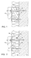
- Fig. 1 shows a cross-sectional view of a fastening device with a diagonal strut 6.
- the fastening device comprises a front power transmission element 1 and a rear power transmission element 2, both of which are plate-shaped and arranged parallel to each other.
- an insulating element 20 Between the front power transmission element 1 and the rear power transmission element 2 is an insulating element 20, which consists for example of easily deformable mineral wool.
- the front power transmission element 1 and the rear power transmission element 2 are connected to each other via the diagonal strut 6 and cross braces 11, formed integrally with these and made of plastic. Instead of plastic, metal can also be used if a higher load is required.
- the insulating element 20 is separated from an insulation 5 of the outer wall 4 by the console housing.
- An armature 3 is passed through a hole in the front power transmission member 1, a hole in the insulating member 5 and a hole in the rear power transmission member 2, and is anchored in the outer wall 4.
- the console housing may alternatively contain only air.
- the force caused by the load has a parallel force component directed parallel to the longitudinal axis of the armature 3 and a vertical force component (shear force) directed perpendicular to the longitudinal axis of the armature 3.
- the parallel force component as far as it is remote from the outer wall 4 (tensile force), from the front power transmission element 1 directly to the armature 3, and as far as the Outside wall 4 is facing (pressure force) from the front power transmission element 1, the cross braces 11 and the diagonal struts 6 transmitted to the outer wall 4.
- the vertical force component is transmitted from the front power transmission element 1 to the cross braces 11 and the diagonal brace 6, so that the armature does not act as a long lever.
- the vertical force component is then transmitted from the transverse struts 11 and the diagonal strut 6 on the rear power transmission element 2 and transmitted from this close to the outer wall 4 on the armature 3, so that only a small bending moment acts on the armature 3.
- the front power transmission element 1 and the rear power transmission element 2 is designed such that a shearing force can only be transmitted from the rear power transmission element 2 to the armature 3.
- the hole in the front power transmission element 1 is formed further than the hole in the rear power transmission element 2.
- the width of the hole in the insulating element 20 is not critical, as long as the insulating element 20 is easily deformable .
- Such a size ratio of the holes in the front power transmission member 1, the insulating member 20 and the rear power transmission member 2 can be achieved, for example, by a conical bore. This type of power transmission essentially also applies to the other embodiments. Deviations are noted.
- a washer 9 is provided as an anti-rotation device through another hole in the front power transmission element 1, another hole in the insulation element 20, and another hole in the rear power transmission element between the nut 8 and the front power transmission element 1 2 and anchored in the wall 4 to prevent rotation of the fastening device.
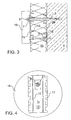
- Fig. 2 shows a cross-sectional view of a fastening device with border 14.
- the vertical force component is transmitted substantially via the insulating member 20a from a front power transmission member 1a to a rear power transmission member 2a and transmitted therefrom to the armature 3.
- the insulating element 20a slightly deforms under the vertical force component (shear force), which is why the insulating element 20a is formed for example of foam glass.
- metal claws 12 are formed, which engage in the insulating element 20 a.
- the rear power transmission element 2a made of plastic has a frame 13 for positive connection with the insulating element 20a.
- a border 14 made of plastic with a bevelled rear side which is also filled with the insulating element 20a and serves to compress a surrounding insulation 5 made of mineral wool, so that there is no gap between the insulation 5 and the fastening device ,
- the frame 14 and the frame 13 together with the power transmission elements 1a and 2a, a console housing.
- claws could be formed on both of the power transmission members 1a and 2a, or claws could be formed on the lower power transmission member 2a and a frame on the upper power transmission member 1a, or could be attached to the upper power transmission member 1a and the lower power transmission element 2a frame may be formed.
- the power transmission elements 1a, 2a may also be additionally or alternatively adhered to the insulating element 20a for this embodiment and the other embodiments.
- Fig. 3 shows a cross-sectional view of a fastening device with a front power transmission element 1 b and a rear power transmission element 2 b, which are connected to each other via an insulating element 5 b.
- the front power transmission element 1 b with claws 12 and the rear power transmission element 2 b with claws 15 are interconnected exclusively via the insulating element 5 b, which with the insulation 5b of the outer wall 4 is identical.
- a console body is not present in this embodiment.
- Fig. 4 shows a view of a fastening device with a circular circumference.
- the front power transmission member 1 c and the rear power transmission member (hidden) are connected to the front and the back of a console body 16 having a circular cross section.
- the claws (hidden) are formed by punching out of the front fastener 1 c and bending for this and the other embodiments, so that recesses 17 arise.
- the console body consists either of an insulating element or comprises a housing in which an insulating element is included.
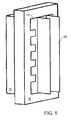
- Fig. 5 shows a perspective view of a fastener, which is designed as a console.
- the console comprises a console body with a front cuboid portion 18 and a rear cuboid portion 19, which form the housing of the console.
- the rear portion 19 has a smaller cross-sectional area than the front portion 18, so that between the front portion 18 and the rear portion 19, a step is formed and the front portion 19 forms a border.
- the border shall cover an insulation surrounding the console, so that no gap is formed between the console and the insulation.
- Fig. 6 shows a cross-sectional view of the fastening device Fig. 5 along its longitudinal direction.
- the fastening device Fig. 5 differs from the fastening device Fig. 2 only in that the border has no bevelled rear side.
- the console is therefore suitable for insulation that hardly yields, such as foam glass.
- Fig. 7 shows a cross-sectional view of the fastening device Fig. 5 along its transverse direction.
- the console body can also be designed as a one-piece insulating element without housing.
Landscapes
- Engineering & Computer Science (AREA)
- Architecture (AREA)
- Civil Engineering (AREA)
- Structural Engineering (AREA)
- Physics & Mathematics (AREA)
- Acoustics & Sound (AREA)
- Electromagnetism (AREA)
- Connection Of Plates (AREA)
Abstract
Description
Die Erfindung betrifft ein Teilesatz umfassend eine Befestigungsvorrichtung und einen Anker gemäß dem Oberbegriff des Patentanspruchs 1.The invention relates to a kit of parts comprising a fastening device and an armature according to the preamble of
Eine solche Befestigungsvorrichtung mit einem vorderen Kraftübertragungselement und einem hinteren Kraftübertragungselement, wobei ein Anker durch das vordere Kraftübertragungselement und das hintere Kraftübertragungselement hindurchführbar ist, ist aus der
Ist die Befestigungsvorrichtung nicht fest eingespannt und ist eine Last an der Befestigungsvorrichtung befestigt, dreht eine parallel zu der senkrechten Außenwand nach unten gerichtete Kraft (Scherkraft), die von der Last verursacht wird, die Befestigungsvorrichtung aufgrund der Toleranzen relativ zu dem Anker, und es wirkt sowohl eine Kraft von dem vorderen Kraftübertragungselement als auch von dem hinteren Kraftübertragungselement auf den Anker ein, so dass ein recht großes Biegemoment auf den Anker ausgeübt wird, wenn die Befestigungsvorrichtung nicht eingespannt ist. Durch ein festes Einspannen könnten zwar Querkräfte vom hinteren Kraftübertragungselement über Reibung direkt auf den Untergrund übertragen werden. Allerdings bedingt dies sehr hohe Zugkräfte im Anker und damit einen groß dimensionierten Anker mit relativ hohem Wärmedurchgang.If the fastening device is not clamped tightly and a load is fastened to the fastening device, one parallel to the vertical outer wall turns downwards directed force (shear force) caused by the load, the fastening device due to the tolerances relative to the armature, and it acts both a force of the front power transmission element and the rear power transmission element on the armature, so that a fairly large bending moment is applied to the anchor when the fastening device is not clamped. By a firm clamping, although lateral forces could be transmitted from the rear power transmission element via friction directly to the ground. However, this requires very high tensile forces in the anchor and thus a large-sized anchor with relatively high heat transfer.
Aus der Offenlegungsschrift
Der vorliegenden Erfindung liegt die Aufgabe zugrunde, eine derartige Befestigungsvorrichtung zu schaffen, welche einfach zu montieren ist.The present invention has for its object to provide such a fastening device, which is easy to assemble.
Die der Erfindung zugrunde liegende Aufgabe wird durch einen Teilesatz mit den Merkmalen des kennzeichnenden Teils des Patentanspruchs 1 gelöst.The object underlying the invention is achieved by a kit of parts with the features of the characterizing part of
Der erfindungsgemäße Teilesatz weist eine Befestigungsvorrichtung mit einem vorderen Kraftübertragungselement und einem hinteren Kraftübertragungselement, sowie einen Anker auf, wobei der Anker durch ein Loch im vorderen Kraftübertragungselement und ein Loch im hinteren Kraftübertragungselement hindurchführbar ist. Der Anker ist in einer Außenwand verankerbar. Das Loch im vorderen Kraftübertragungselement ist weiter ausgebildet ist als das Loch im hinteren Kraftübertragungselement, so dass, wenn die Befestigungsvorrichtung relativ zum Anker gedreht wird, die Drehung der Befestigungsvorrichtung dadurch begrenzt wird, dass der Anker gegen zwei gegenüberliegende Ränder des Lochs im hinteren Kraftübertragungselement stößt, durch welches der Anker hindurchgeführt ist. Der Anker liegt nicht am Loch im vorderen Kraftübertragungselement an, wodurch im montierten Zustand eine durch eine Last hervorgerufene Scherkraft vom vorderen Kraftübertragungselement auf das hintere Kraftübertragungselement und ausschließlich von diesem direkt an der Außenwand auf den Anker übertragbar ist.The kit of parts according to the invention comprises a fastening device with a front power transmission element and a rear power transmission element, and an armature, wherein the armature through a hole in the front power transmission element and a hole in the rear power transmission element can be passed. The anchor is anchored in an outer wall. The hole in the front power transmission member is formed wider than the hole in the rear power transmission member such that when the fastening device is rotated relative to the armature, the rotation of the fastening device is limited by the armature abutting two opposite edges of the hole in the rear power transmission member. through which the anchor is passed. The armature does not abut the hole in the front power transmission member, whereby a shearing force caused by a load in the mounted state is transferable from the front power transmission member to the rear power transmission member and exclusively from the latter directly to the outer wall on the armature.
Kennzeichnend für den erfindungsgemäßen Teilesatz ist, dass der Anker die Befestigungsvorrichtung derart fixiert, dass eine durch eine Last hervorgerufene Zugkraft vom vorderen Kraftübertragungselement direkt auf den Anker übertragbar ist.Characteristic of the kit of parts according to the invention is that the anchor fixes the fastening device such that a tensile force caused by a load from the front power transmission element is directly transferable to the anchor.
Erfindungsgemäß sind das vordere Kraftübertragungselement und das hintere Kraftübertragungselement derart ausgebildet, dass eine Scherkraft ausschließlich von dem hinteren Kraftübertragungselement auf den Anker übertragbar ist. Dabei meint der Begriff "ausschließlich", dass zumindest der überwiegende Anteil der Scherkraft von dem hinteren Kraftübertragungselement auf den Anker übertragbar ist, denn auch wenn ein geringer Anteil der Scherkraft, beispielsweise über eine Silikonabdichtung zwischen Anker und vorderem Kraftübertragungselement, übertragen wird, bleibt der Vorteil erhalten, dass gegenüber den bekannten Befestigungsvorrichtungen ein vergleichsweise kleinerer Anker verwendet werden kann.According to the invention, the front power transmission element and the rear power transmission element are designed such that a shearing force can be transmitted exclusively from the rear power transmission element to the armature. Here, the term "exclusively" means that at least the vast majority of the shear force from the rear power transmission element is transferable to the anchor, because even if a small proportion of the shear force, for example via a silicone seal between the armature and front power transmission element is transmitted, the advantage remains obtained that compared to the known fastening devices, a comparatively smaller anchor can be used.
Vorteilhafterweise kann eine Scherkraft in unmittelbarer Nähe der Außenwand auf den Anker übertragen werden, so dass auf den Anker kein großes Biegemoment wirkt. Daher reicht ein relativ dünner Anker aus und wird keine großflächige Wärmebrücke gebildet. Der Begriff "Anker" ist in diesem Zusammenhang sehr umfassend zu verstehen und soll jedes beliebige Element bezeichnen, das in der Außenwand verankerbar ist.Advantageously, a shearing force in the immediate vicinity of the outer wall can be transferred to the armature so that no large bending moment acts on the armature. Therefore, a relatively thin anchor is sufficient and no large-scale thermal bridge is formed. The term "anchor" is to be understood in this context as very comprehensive and is intended to denote any element that can be anchored in the outer wall.
In einer Weiterbildung der bevorzugten Ausführungsform sind das vordere Kraftübertragungselement und das hintere Kraftübertragungselement derart ausgebildet, dass eine Scherkraft von dem vorderen Kraftübertragungselement über ein Dämmelement auf das hintere Kraftübertragungselement übertragbar ist.In a development of the preferred embodiment, the front power transmission element and the rear power transmission element are designed such that a Shearing force of the front power transmission element via an insulating element to the rear power transmission element is transferable.
Vorteilhafterweise kann eine besonders gute Isolierung erreicht werden.Advantageously, a particularly good insulation can be achieved.
In noch einer Weiterbildung der bevorzugten Ausführungsform sind an dem vorderen Kraftübertragungselement Krallen ausgebildet, die in das Dämmelement eingreifen. Dabei sind "Krallen" allgemein und breit als eine formschlüssige Verbindung zu verstehen.In yet another embodiment of the preferred embodiment, claws are formed on the front power transmission element, which engage in the insulating element. Here, "claws" are generally and widely to be understood as a positive connection.
Alternativ zu einer formschlüssigen Verbindung ist auch eine stoffschlüssige Verbindung, insbesondere auf Basis einer Verklebung möglich. Dies ermöglicht besonders einfache Bauteilgeometrien.As an alternative to a positive connection, a material connection, in particular based on a bond is possible. This allows particularly simple component geometries.
Vorteilhafterweise sind Krallen besonders geeignet zur Übertragung einer Kraft, die senkrecht zu der Längsachse des Ankers gerichtet ist.Advantageously, claws are particularly suitable for transmitting a force which is directed perpendicular to the longitudinal axis of the armature.
In noch einer Weiterbildung der bevorzugten Ausführungsform sind auch an dem hinteren Kraftübertragungselement Krallen ausgebildet, die in das Dämmelement eingreifen.In yet another embodiment of the preferred embodiment, claws are formed on the rear power transmission element, which engage in the insulating element.
In noch einer bevorzugten Ausführungsform sind das vordere Kraftübertragungselement und das hintere Kraftübertragungselement über eine Diagonalstrebe miteinander verbunden.In yet a preferred embodiment, the front power transmission element and the rear power transmission element are interconnected via a diagonal strut.
Vorteilhafterweise ist kein Dämmelement mit großer Schersteifigkeit zwischen den beiden Kraftübertragungselementen erforderlich.Advantageously, no insulating element with high shear stiffness between the two power transmission elements is required.
In noch einer bevorzugten Ausführungsform weist die Befestigungsvorrichtung einen Konsolenkörper auf, mit dem das hintere Kraftübertragungselement und das vordere Kraftübertragungselement verbunden sind.In yet a preferred embodiment, the attachment device comprises a console body to which the rear power transmission element and the front power transmission element are connected.
Vorteilhafterweise kann ein derartiger Konsolenkörper mit geringer Wärmeleitfähigkeit hergestellt werden.Advantageously, such a console body with low thermal conductivity can be produced.
In einer Weiterbildung der bevorzugten Ausführungsform ist der Konsolenkörper rund. Er lässt sich dadurch einfach in eine vorhandene Wärmeisolierung, beispielsweise eine Schicht Mineralwolle, einpassen, indem mit einer Lochsäge eine passende Aussparung in der Wärmeisolierung erstellt wird.In a development of the preferred embodiment, the console body is round. He can thus easily in an existing thermal insulation, such as a Layer of mineral wool, fit by using a hole saw a matching recess in the thermal insulation is created.
In einer Weiterbildung der bevorzugten Ausführungsform weist der Konsolenkörper eine Umrandung auf.In a development of the preferred embodiment, the console body has a border.
Vorteilhafterweise kann ein Spalt zwischen dem Konsolenkörper und der Isolierung vermieden werden.Advantageously, a gap between the console body and the insulation can be avoided.
In noch einer bevorzugten Ausführungsform weist die Befestigungsvorrichtung eine Verdrehsicherung auf, die ein Verdrehen insbesondere des hinteren Kraftübertragungselements gegenüber der Wand verhindert. Dabei ist ein mögliches Verdrehen um eine zum Anker im Wesentlichen parallele Achse gemeint. Vorzugsweise ist als solche Verdrehsicherung ein weiterer Anker durch das vordere Kraftübertragungselement und das hintere Kraftübertragungselement hindurchführbar.In yet a preferred embodiment, the fastening device has an anti-rotation device which prevents twisting, in particular of the rear power transmission element relative to the wall. In this case, a possible rotation about an axis substantially parallel to the armature is meant. Preferably, as such anti-rotation another anchor through the front power transmission element and the rear power transmission element can be passed.
Vorteilhafterweise kann eine Drehung der Kraftübertragungsvorrichtung verhindert werden.Advantageously, rotation of the power transmission device can be prevented.
Die Erfindung wird nachfolgend anhand der Zeichnungen näher beschrieben.The invention will be described in more detail with reference to the drawings.
Es zeigen:
- Fig. 1
- eine Querschnittsansicht einer Befestigungsvorrichtung mit einer Diagonalstrebe;
- Fig. 2
- eine Querschnittsansicht einer Befestigungsvorrichtung mit einer Umrandung;
- Fig. 3
- eine Querschnittsansicht einer Befestigungsvorrichtung mit einem vorderen Kraftübertragungselement und einem hinteren Kraftübertragungselement, die nur über ein Dämmelement miteinander verbunden sind;
- Fig. 4
- eine Ansicht einer Befestigungsvorrichtung mit kreisförmigem Umfang;
- Fig. 5
- eine perspektivische Ansicht einer Befestigungsvorrichtung, welche als Konsole ausgebildet ist;
- Fig. 6
- eine Querschnittsansicht der Befestigungsvorrichtung aus
Fig. 5 entlang dessen Längsrichtung; und - Fig. 7
- eine Querschnittsansicht der Befestigungsvorrichtung aus
Fig. 5 entlang dessen Querrichtung.
- Fig. 1
- a cross-sectional view of a fastening device with a diagonal strut;
- Fig. 2
- a cross-sectional view of a fastening device with a border;
- Fig. 3
- a cross-sectional view of a fastening device with a front power transmission element and a rear power transmission element, which are interconnected only via an insulating element;
- Fig. 4
- a view of a fastening device with a circular circumference;
- Fig. 5
- a perspective view of a fastening device which is designed as a console;
- Fig. 6
- a cross-sectional view of the fastening device
Fig. 5 along its longitudinal direction; and - Fig. 7
- a cross-sectional view of the fastening device
Fig. 5 along its transverse direction.
Die durch die Last hervorgerufene Kraft hat eine parallele Kraftkomponente, die parallel zu der Längsachse des Ankers 3 gerichtet ist, und eine senkrechte Kraftkomponente (Scherkraft), die senkrecht zu der Längsachse des Ankers 3 gerichtet ist. Die parallele Kraftkomponente wird, soweit sie von der Außenwand 4 abgewandt ist (Zugkraft), von dem vorderen Kraftübertragungselement 1 direkt auf den Anker 3, und soweit sie der Außenwand 4 zugewandt ist (Druckkraft) vom vorderen Kraftübertragungselement 1, die Querstreben 11 und die Diagonalstreben 6 auf die Außenwand 4 übertragen. Die senkrechte Kraftkomponente wird von dem vorderen Kraftübertragungselement 1 auf die Querstreben 11 und die Diagonalstrebe 6 übertragen, so dass der Anker nicht als langer Hebel wirkt. Die senkrechte Kraftkomponente wird dann von den Querstreben 11 und der Diagonalstrebe 6 auf das hintere Kraftübertragungselement 2 übertragen und von diesem dicht bei der Außenwand 4 auf den Anker 3 übertragen, so dass nur ein geringes Biegemoment auf den Anker 3 wirkt. Um sicherzustellen, dass die senkrechte Kraftkomponente erst bei dem hinteren Kraftübertragungselement 2 auf den Anker 3 einwirkt, ist das vordere Kraftübertragungselement 1 und das hintere Kraftübertragungselement 2 derart ausgebildet, dass eine Scherkraft ausschließlich von dem hinteren Kraftübertragungselement 2 auf den Anker 3 übertragbar ist. Konkret bedeutet dies, dass, wenn die Befestigungsvorrichtung relativ zu dem Anker 3 aufgrund von Toleranzen der Löcher in dem vorderen Kraftübertragungselement 1 und dem hinteren Kraftübertragungselement 2 gedreht wird, die Drehung der Befestigungsvorrichtung dadurch begrenzt wird, dass der Anker 3 gegen zwei gegenüberliegende Ränder des Lochs in dem hinteren Kraftübertragungselement 2 stößt, durch welches der Anker 3 hindurchgeführt ist, wobei der Anker 3 weder an dem Loch in dem vorderen Kraftübertragungselement 1 noch an dem Loch in dem Dämmelement 20 anliegt. Dazu wird für eine identische Dicke der plattenförmigen Kraftübertragungselemente 1 und 2 das Loch in dem vorderen Kraftübertragungselement 1 weiter ausgebildet als das Loch in dem hinteren Kraftübertragungselement 2. Die Weite des Loch in dem Dämmelement 20 ist jedoch nicht kritisch, solange das Dämmelement 20 leicht verformbar ist. Ein solches Größenverhältnis der Löcher in dem vorderen Kraftübertragungselement 1, dem Dämmelement 20 und dem hinteren Kraftübertragungselement 2 kann zum Beispiel durch eine konische Bohrung erreicht werden. Diese Art der Kraftübertragung gilt im Wesentlichen auch für die weiteren Ausführungsformen. Abweichungen sind angemerkt.The force caused by the load has a parallel force component directed parallel to the longitudinal axis of the
Zur Fixierung der Befestigungsvorrichtung ist eine Mutter 8 auf den Anker 3 geschraubt. Zwischen der Mutter 8 und dem vorderen Kraftübertragungselement 1 befindet sich eine Unterlegscheibe bzw. ein Unterlegplättchen 7. Ein Kunststoffstift 9 als Verdrehsicherung ist durch ein weiteres Loch in dem vorderen Kraftübertragungselement 1, ein weiteres Loch in dem Dämmelement 20 und ein weiteres Loch in dem hinteren Kraftübertragungselement 2 hindurchgeführt und ist in der Wand 4 verankert, um eine Drehung der Befestigungsvorrichtung zu verhindern.To fix the fastening device, a
Im Folgenden werden identische Elemente mit den gleichen Bezugszeichen bezeichnet und werden Buchstaben zu den Bezugszeichen hinzugefügt, um abgewandelte Elemente zu kennzeichnen.Hereinafter, identical elements will be denoted by the same reference numerals, and letters will be added to the reference numerals to designate modified elements.
Claims (11)
- Set of parts, comprising a fixing device having a front force-transmission element (1, 1a, 1b, 1c, 1d) and a rear force-transmission element (2, 2a, 2b, 2d), and an anchor (3),- wherein the anchor (3) is arranged to be passed through a hole in the front force-transmission element (1, 1a, 1b, 1c, 1d) and a hole in the rear force-transmission element (2, 2a, 2b, 2d),- wherein the anchor (3) is arranged to be anchored in an outer wall (4),- wherein the hole in the front force-transmission element (1, 1a, 1b, 1c, 1d) is wider than the hole in the rear force-transmission element (2, 2a, 2b, 2d) so that, when the fixing device is rotated relative to the anchor (3), the rotation of the fixing device is limited by the anchor (3) striking against two oppositely located edges of the hole in the rear force-transmission element (2, 2a, 2b, 2d) through which the anchor (3) passes, and- wherein the anchor (3) is not in contact with the hole in the front force-transmission element (1), with the result that, in the mounted state, a shearing force brought about by a load can be transmitted from the front force-transmission element (1, 1a, 1b, 1c, 1d) to the rear force-transmission element (2, 2a, 2b, 2d) and exclusively from the latter to the anchor (3) directly at the outer wall (4),characterised in that- the anchor (3) secures the fixing device in such a way that a tensile force brought about by a load can be transmitted from the front force-transmission element (1, 1a, 1b, 1c, 1d) directly to the anchor (3).
- Set of parts according to claim 1, characterised in that the front force-transmission element (1a, 1b, 1d) and the rear force-transmission element (2a, 2b, 2d) are constructed in such a way that a shearing force can be transmitted from the front force-transmission element (1a, 1b, 1d) via an insulating element (20a, 5b, 20d) to the rear force-transmission element (2a, 2b, 2d).
- Set of parts according to claim 2, characterised in that claws (12) are formed on the front force-transmission element (1a, 1b, 1d), which claws engage in the insulating element (20a, 5b, 20d).
- Set of parts according to claim 3, characterised in that claws are formed on the rear force-transmission element (2b), which claws engage in the insulating element (5b).
- Set of parts according to any one of the preceding claims, characterised in that the front and/or rear force-transmission element(s) (1a, 2a) is/are joined to the insulating element (20a) by means of a material-bonded connection, especially by means of an adhesive bond.
- Set of parts according to any one of the preceding claims, characterised in that the front force-transmission element (1) and the rear force-transmission element (2) are joined to one another by means of a diagonal strut (6).
- Set of parts according to any one of the preceding claims, characterised in that the fixing device has a bracket element (16) to which the rear force-transmission element (1, 1a, 1b, 1c, 1d) and the front force-transmission element (2, 2a, 2b, 2d) are joined.
- Set of parts according to claim 7, characterised in that the bracket element (16) is round.
- Set of parts according to claim 8, characterised in that the bracket element has an edging.
- Set of parts according to any one of the preceding claims, characterised in that the fixing device has an anti-rotation device (9).
- Set of parts according to claim 10, characterised in that, as anti-rotation device, a further anchor (9) can be passed through the front force-transmission element (1, 1a, 1b, 1c, 1d) and the rear force-transmission element (2, 2a, 2d).
Applications Claiming Priority (3)
| Application Number | Priority Date | Filing Date | Title |
|---|---|---|---|
| DE102007009330 | 2007-02-22 | ||
| DE102007013509A DE102007013509A1 (en) | 2007-02-22 | 2007-03-21 | fastening device |
| PCT/EP2008/001104 WO2008101624A1 (en) | 2007-02-22 | 2008-02-14 | Fastening device |
Publications (2)
| Publication Number | Publication Date |
|---|---|
| EP2122084A1 EP2122084A1 (en) | 2009-11-25 |
| EP2122084B1 true EP2122084B1 (en) | 2012-06-27 |
Family
ID=39646124
Family Applications (1)
| Application Number | Title | Priority Date | Filing Date |
|---|---|---|---|
| EP08707707A Not-in-force EP2122084B1 (en) | 2007-02-22 | 2008-02-14 | Set comprising a fastening device and an anchor |
Country Status (3)
| Country | Link |
|---|---|
| EP (1) | EP2122084B1 (en) |
| DE (1) | DE102007013509A1 (en) |
| WO (1) | WO2008101624A1 (en) |
Cited By (1)
| Publication number | Priority date | Publication date | Assignee | Title |
|---|---|---|---|---|
| US8919070B2 (en) | 2012-08-30 | 2014-12-30 | Technoform Holding GmbH | Spacer for retaining cladding element on structural building element |
Families Citing this family (4)
| Publication number | Priority date | Publication date | Assignee | Title |
|---|---|---|---|---|
| DE202010002347U1 (en) * | 2009-09-22 | 2011-08-26 | Kurt Sextl | Device for fastening objects |
| DE102011056474A1 (en) * | 2011-12-15 | 2013-06-20 | Fischerwerke Gmbh & Co. Kg | mounting assembly |
| FR2986023B1 (en) * | 2012-01-25 | 2015-02-20 | Fournier Daforib | SUPPORT DEVICE FOR SUPPORTING AN ANCHORING ROD WHICH IS INSERTED IN A WALL TO SURROUND FROM IT. |
| EP3786378A1 (en) * | 2019-08-29 | 2021-03-03 | Hilti Aktiengesellschaft | Attachment device |
Family Cites Families (10)
| Publication number | Priority date | Publication date | Assignee | Title |
|---|---|---|---|---|
| DE2708095A1 (en) * | 1977-02-25 | 1978-08-31 | Gyproc Gmbh | PROCEDURE AND SPACER FOR FASTENING A COMPOSITE ELEMENT TO A SUPPORTING STRUCTURE |
| DE3146188C1 (en) * | 1981-11-21 | 1983-06-09 | Werner Flosbach GmbH & Co KG, 5272 Wipperfürth | Device for attaching a layer of insulating material to a wall |
| FR2520413B1 (en) * | 1982-01-26 | 1985-08-16 | Calafel Claude | SELF-SUPPORTING WALL PANEL FOR INTERIOR AND EXTERIOR CONSTRUCTION WALLS |
| CH666310A5 (en) * | 1984-07-18 | 1988-07-15 | Peter Schaer Ag | Facade cladding fixing device - comprises bracket extending through insulation material and accommodating anchoring member for cladding |
| US5063722A (en) * | 1989-03-31 | 1991-11-12 | Hohmann Enterprises, Inc. | Gripstay channel veneer anchor assembly |
| EP0651113B1 (en) * | 1993-07-29 | 1996-01-03 | Schuler, Jörg, Dipl.-Ing. | Fastening device for plate-like façade elements |
| DE29509418U1 (en) | 1995-06-08 | 1996-10-10 | Blankenburg, Wolf-Rüdiger, 82152 Planegg | Adjustable fastening device |
| DE19704112C2 (en) * | 1996-12-04 | 2001-10-18 | Peter Kellner | Insulating facade cladding |
| DE10064679A1 (en) * | 2000-12-22 | 2002-07-04 | Fischer Artur Werke Gmbh | Spacers for fastening a component to a wall or the like which has an insulation layer, and method and tool for setting the spacer |
| DE202004007266U1 (en) * | 2004-05-06 | 2005-09-15 | Fischer Artur Werke Gmbh | Profile to be attached to outer wall of building, using two plastic sleeves for insulation |
-
2007
- 2007-03-21 DE DE102007013509A patent/DE102007013509A1/en not_active Withdrawn
-
2008
- 2008-02-14 WO PCT/EP2008/001104 patent/WO2008101624A1/en active Application Filing
- 2008-02-14 EP EP08707707A patent/EP2122084B1/en not_active Not-in-force
Cited By (1)
| Publication number | Priority date | Publication date | Assignee | Title |
|---|---|---|---|---|
| US8919070B2 (en) | 2012-08-30 | 2014-12-30 | Technoform Holding GmbH | Spacer for retaining cladding element on structural building element |
Also Published As
| Publication number | Publication date |
|---|---|
| WO2008101624A1 (en) | 2008-08-28 |
| DE102007013509A1 (en) | 2008-08-28 |
| EP2122084A1 (en) | 2009-11-25 |
Similar Documents
| Publication | Publication Date | Title |
|---|---|---|
| WO2003048591A1 (en) | Connecting nut for screwing constructional elements to a platelike component | |
| DE3420696C1 (en) | Clamping fixture for fastening and/or connecting glass panes, in particular for facade panels consisting of toughened safety glass | |
| EP2122084B1 (en) | Set comprising a fastening device and an anchor | |
| EP1533185A1 (en) | Tolerance deviation compensation element | |
| DE4119934C2 (en) | ||
| EP2636830B1 (en) | Door hinge fastening, assembly comprising the door hinge fastening and a door hinge and door assembly | |
| DE10029343C2 (en) | Connection for firmly connecting at least two elements | |
| EP0738807A2 (en) | Angle connector for reveal surface | |
| AT520816B1 (en) | Mounting bracket and mounting arrangement | |
| DE10351446B4 (en) | threaded plate | |
| EP4274939A1 (en) | Wall holder for a rear-ventilated curtain façade, and rear-ventilated curtain façade | |
| EP2323871B1 (en) | Airbag system | |
| EP3333336A1 (en) | Bracket anchor | |
| EP1088943A2 (en) | Mounting support system with installation aid | |
| EP1860268B1 (en) | Device for mounting a sheet of glass | |
| DE102005003186A1 (en) | Device for connecting components, e.g. loudspeakers and vehicle doors, has pre-formed attachment region for shape-locking connection to attachment arrangement fitted through opening of second component after removing deformation region | |
| DE102008062231B4 (en) | Fastening arrangement for attaching a sanitary fitting and adapter | |
| DE19908886C1 (en) | Actuator, in particular for heating, ventilation or air conditioning flaps in motor vehicles | |
| DE202016007201U1 (en) | Clothing surface substructure unit | |
| DE202021106848U1 (en) | Modular lattice railing for a French balcony | |
| EP1096156A2 (en) | Preassembled securing screw | |
| WO2023023684A1 (en) | Fastening arrangement for a facade with facade elements, and facade comprising the fastening arrangement | |
| DE102014114912A1 (en) | Device for providing an attachment point to a profile element | |
| DE3314626C2 (en) | Bracket for an air duct and kit for it | |
| DE202014100214U1 (en) | Device for fixing a structure |
Legal Events
| Date | Code | Title | Description |
|---|---|---|---|
| PUAI | Public reference made under article 153(3) epc to a published international application that has entered the european phase |
Free format text: ORIGINAL CODE: 0009012 |
|
| 17P | Request for examination filed |
Effective date: 20090617 |
|
| AK | Designated contracting states |
Kind code of ref document: A1 Designated state(s): AT BE BG CH CY CZ DE DK EE ES FI FR GB GR HR HU IE IS IT LI LT LU LV MC MT NL NO PL PT RO SE SI SK TR |
|
| 17Q | First examination report despatched |
Effective date: 20091123 |
|
| DAX | Request for extension of the european patent (deleted) | ||
| GRAP | Despatch of communication of intention to grant a patent |
Free format text: ORIGINAL CODE: EPIDOSNIGR1 |
|
| RTI1 | Title (correction) |
Free format text: SET COMPRISING A FASTENING DEVICE AND AN ANCHOR |
|
| GRAS | Grant fee paid |
Free format text: ORIGINAL CODE: EPIDOSNIGR3 |
|
| GRAA | (expected) grant |
Free format text: ORIGINAL CODE: 0009210 |
|
| AK | Designated contracting states |
Kind code of ref document: B1 Designated state(s): AT BE BG CH CY CZ DE DK EE ES FI FR GB GR HR HU IE IS IT LI LT LU LV MC MT NL NO PL PT RO SE SI SK TR |
|
| REG | Reference to a national code |
Ref country code: GB Ref legal event code: FG4D Free format text: NOT ENGLISH |
|
| REG | Reference to a national code |
Ref country code: CH Ref legal event code: EP |
|
| REG | Reference to a national code |
Ref country code: AT Ref legal event code: REF Ref document number: 564344 Country of ref document: AT Kind code of ref document: T Effective date: 20120715 |
|
| REG | Reference to a national code |
Ref country code: IE Ref legal event code: FG4D Free format text: LANGUAGE OF EP DOCUMENT: GERMAN |
|
| REG | Reference to a national code |
Ref country code: DE Ref legal event code: R096 Ref document number: 502008007586 Country of ref document: DE Effective date: 20120830 |
|
| PG25 | Lapsed in a contracting state [announced via postgrant information from national office to epo] |
Ref country code: NO Free format text: LAPSE BECAUSE OF FAILURE TO SUBMIT A TRANSLATION OF THE DESCRIPTION OR TO PAY THE FEE WITHIN THE PRESCRIBED TIME-LIMIT Effective date: 20120927 Ref country code: SE Free format text: LAPSE BECAUSE OF FAILURE TO SUBMIT A TRANSLATION OF THE DESCRIPTION OR TO PAY THE FEE WITHIN THE PRESCRIBED TIME-LIMIT Effective date: 20120627 Ref country code: LT Free format text: LAPSE BECAUSE OF FAILURE TO SUBMIT A TRANSLATION OF THE DESCRIPTION OR TO PAY THE FEE WITHIN THE PRESCRIBED TIME-LIMIT Effective date: 20120627 Ref country code: FI Free format text: LAPSE BECAUSE OF FAILURE TO SUBMIT A TRANSLATION OF THE DESCRIPTION OR TO PAY THE FEE WITHIN THE PRESCRIBED TIME-LIMIT Effective date: 20120627 |
|
| REG | Reference to a national code |
Ref country code: NL Ref legal event code: VDEP Effective date: 20120627 |
|
| REG | Reference to a national code |
Ref country code: LT Ref legal event code: MG4D Effective date: 20120627 |
|
| PG25 | Lapsed in a contracting state [announced via postgrant information from national office to epo] |
Ref country code: GR Free format text: LAPSE BECAUSE OF FAILURE TO SUBMIT A TRANSLATION OF THE DESCRIPTION OR TO PAY THE FEE WITHIN THE PRESCRIBED TIME-LIMIT Effective date: 20120928 Ref country code: SI Free format text: LAPSE BECAUSE OF FAILURE TO SUBMIT A TRANSLATION OF THE DESCRIPTION OR TO PAY THE FEE WITHIN THE PRESCRIBED TIME-LIMIT Effective date: 20120627 Ref country code: LV Free format text: LAPSE BECAUSE OF FAILURE TO SUBMIT A TRANSLATION OF THE DESCRIPTION OR TO PAY THE FEE WITHIN THE PRESCRIBED TIME-LIMIT Effective date: 20120627 Ref country code: HR Free format text: LAPSE BECAUSE OF FAILURE TO SUBMIT A TRANSLATION OF THE DESCRIPTION OR TO PAY THE FEE WITHIN THE PRESCRIBED TIME-LIMIT Effective date: 20120627 |
|
| PG25 | Lapsed in a contracting state [announced via postgrant information from national office to epo] |
Ref country code: CY Free format text: LAPSE BECAUSE OF FAILURE TO SUBMIT A TRANSLATION OF THE DESCRIPTION OR TO PAY THE FEE WITHIN THE PRESCRIBED TIME-LIMIT Effective date: 20120627 Ref country code: RO Free format text: LAPSE BECAUSE OF FAILURE TO SUBMIT A TRANSLATION OF THE DESCRIPTION OR TO PAY THE FEE WITHIN THE PRESCRIBED TIME-LIMIT Effective date: 20120627 Ref country code: EE Free format text: LAPSE BECAUSE OF FAILURE TO SUBMIT A TRANSLATION OF THE DESCRIPTION OR TO PAY THE FEE WITHIN THE PRESCRIBED TIME-LIMIT Effective date: 20120627 Ref country code: SK Free format text: LAPSE BECAUSE OF FAILURE TO SUBMIT A TRANSLATION OF THE DESCRIPTION OR TO PAY THE FEE WITHIN THE PRESCRIBED TIME-LIMIT Effective date: 20120627 Ref country code: IS Free format text: LAPSE BECAUSE OF FAILURE TO SUBMIT A TRANSLATION OF THE DESCRIPTION OR TO PAY THE FEE WITHIN THE PRESCRIBED TIME-LIMIT Effective date: 20121027 Ref country code: CZ Free format text: LAPSE BECAUSE OF FAILURE TO SUBMIT A TRANSLATION OF THE DESCRIPTION OR TO PAY THE FEE WITHIN THE PRESCRIBED TIME-LIMIT Effective date: 20120627 |
|
| PG25 | Lapsed in a contracting state [announced via postgrant information from national office to epo] |
Ref country code: PT Free format text: LAPSE BECAUSE OF FAILURE TO SUBMIT A TRANSLATION OF THE DESCRIPTION OR TO PAY THE FEE WITHIN THE PRESCRIBED TIME-LIMIT Effective date: 20121029 Ref country code: PL Free format text: LAPSE BECAUSE OF FAILURE TO SUBMIT A TRANSLATION OF THE DESCRIPTION OR TO PAY THE FEE WITHIN THE PRESCRIBED TIME-LIMIT Effective date: 20120627 Ref country code: IT Free format text: LAPSE BECAUSE OF FAILURE TO SUBMIT A TRANSLATION OF THE DESCRIPTION OR TO PAY THE FEE WITHIN THE PRESCRIBED TIME-LIMIT Effective date: 20120627 |
|
| PG25 | Lapsed in a contracting state [announced via postgrant information from national office to epo] |
Ref country code: NL Free format text: LAPSE BECAUSE OF FAILURE TO SUBMIT A TRANSLATION OF THE DESCRIPTION OR TO PAY THE FEE WITHIN THE PRESCRIBED TIME-LIMIT Effective date: 20120627 |
|
| PG25 | Lapsed in a contracting state [announced via postgrant information from national office to epo] |
Ref country code: DK Free format text: LAPSE BECAUSE OF FAILURE TO SUBMIT A TRANSLATION OF THE DESCRIPTION OR TO PAY THE FEE WITHIN THE PRESCRIBED TIME-LIMIT Effective date: 20120627 Ref country code: ES Free format text: LAPSE BECAUSE OF FAILURE TO SUBMIT A TRANSLATION OF THE DESCRIPTION OR TO PAY THE FEE WITHIN THE PRESCRIBED TIME-LIMIT Effective date: 20121008 |
|
| PLBE | No opposition filed within time limit |
Free format text: ORIGINAL CODE: 0009261 |
|
| STAA | Information on the status of an ep patent application or granted ep patent |
Free format text: STATUS: NO OPPOSITION FILED WITHIN TIME LIMIT |
|
| 26N | No opposition filed |
Effective date: 20130328 |
|
| REG | Reference to a national code |
Ref country code: DE Ref legal event code: R097 Ref document number: 502008007586 Country of ref document: DE Effective date: 20130328 |
|
| PG25 | Lapsed in a contracting state [announced via postgrant information from national office to epo] |
Ref country code: BG Free format text: LAPSE BECAUSE OF FAILURE TO SUBMIT A TRANSLATION OF THE DESCRIPTION OR TO PAY THE FEE WITHIN THE PRESCRIBED TIME-LIMIT Effective date: 20120927 |
|
| BERE | Be: lapsed |
Owner name: FISCHERWERKE G.M.B.H. & CO. KG Effective date: 20130228 |
|
| PG25 | Lapsed in a contracting state [announced via postgrant information from national office to epo] |
Ref country code: MC Free format text: LAPSE BECAUSE OF NON-PAYMENT OF DUE FEES Effective date: 20130228 |
|
| REG | Reference to a national code |
Ref country code: CH Ref legal event code: PL |
|
| GBPC | Gb: european patent ceased through non-payment of renewal fee |
Effective date: 20130214 |
|
| PG25 | Lapsed in a contracting state [announced via postgrant information from national office to epo] |
Ref country code: LI Free format text: LAPSE BECAUSE OF NON-PAYMENT OF DUE FEES Effective date: 20130228 Ref country code: CH Free format text: LAPSE BECAUSE OF NON-PAYMENT OF DUE FEES Effective date: 20130228 |
|
| REG | Reference to a national code |
Ref country code: FR Ref legal event code: ST Effective date: 20131031 |
|
| REG | Reference to a national code |
Ref country code: IE Ref legal event code: MM4A |
|
| PG25 | Lapsed in a contracting state [announced via postgrant information from national office to epo] |
Ref country code: GB Free format text: LAPSE BECAUSE OF NON-PAYMENT OF DUE FEES Effective date: 20130214 Ref country code: IE Free format text: LAPSE BECAUSE OF NON-PAYMENT OF DUE FEES Effective date: 20130214 Ref country code: FR Free format text: LAPSE BECAUSE OF NON-PAYMENT OF DUE FEES Effective date: 20130228 Ref country code: BE Free format text: LAPSE BECAUSE OF NON-PAYMENT OF DUE FEES Effective date: 20130228 |
|
| REG | Reference to a national code |
Ref country code: AT Ref legal event code: MM01 Ref document number: 564344 Country of ref document: AT Kind code of ref document: T Effective date: 20130214 |
|
| PG25 | Lapsed in a contracting state [announced via postgrant information from national office to epo] |
Ref country code: AT Free format text: LAPSE BECAUSE OF NON-PAYMENT OF DUE FEES Effective date: 20130214 |
|
| PG25 | Lapsed in a contracting state [announced via postgrant information from national office to epo] |
Ref country code: MT Free format text: LAPSE BECAUSE OF FAILURE TO SUBMIT A TRANSLATION OF THE DESCRIPTION OR TO PAY THE FEE WITHIN THE PRESCRIBED TIME-LIMIT Effective date: 20120627 |
|
| PG25 | Lapsed in a contracting state [announced via postgrant information from national office to epo] |
Ref country code: TR Free format text: LAPSE BECAUSE OF FAILURE TO SUBMIT A TRANSLATION OF THE DESCRIPTION OR TO PAY THE FEE WITHIN THE PRESCRIBED TIME-LIMIT Effective date: 20120627 |
|
| PG25 | Lapsed in a contracting state [announced via postgrant information from national office to epo] |
Ref country code: LU Free format text: LAPSE BECAUSE OF NON-PAYMENT OF DUE FEES Effective date: 20130214 Ref country code: HU Free format text: LAPSE BECAUSE OF FAILURE TO SUBMIT A TRANSLATION OF THE DESCRIPTION OR TO PAY THE FEE WITHIN THE PRESCRIBED TIME-LIMIT; INVALID AB INITIO Effective date: 20080214 |
|
| PGFP | Annual fee paid to national office [announced via postgrant information from national office to epo] |
Ref country code: DE Payment date: 20210130 Year of fee payment: 14 |
|
| REG | Reference to a national code |
Ref country code: DE Ref legal event code: R119 Ref document number: 502008007586 Country of ref document: DE |
|
| PG25 | Lapsed in a contracting state [announced via postgrant information from national office to epo] |
Ref country code: DE Free format text: LAPSE BECAUSE OF NON-PAYMENT OF DUE FEES Effective date: 20220901 |