EP2121280B1 - Système de contrôle électrohydraulique - Google Patents
Système de contrôle électrohydraulique Download PDFInfo
- Publication number
- EP2121280B1 EP2121280B1 EP07856849.0A EP07856849A EP2121280B1 EP 2121280 B1 EP2121280 B1 EP 2121280B1 EP 07856849 A EP07856849 A EP 07856849A EP 2121280 B1 EP2121280 B1 EP 2121280B1
- Authority
- EP
- European Patent Office
- Prior art keywords
- pressure
- control arrangement
- speed
- main control
- control
- Prior art date
- Legal status (The legal status is an assumption and is not a legal conclusion. Google has not performed a legal analysis and makes no representation as to the accuracy of the status listed.)
- Active
Links
Images

Classifications
-
- F—MECHANICAL ENGINEERING; LIGHTING; HEATING; WEAPONS; BLASTING
- F04—POSITIVE - DISPLACEMENT MACHINES FOR LIQUIDS; PUMPS FOR LIQUIDS OR ELASTIC FLUIDS
- F04B—POSITIVE-DISPLACEMENT MACHINES FOR LIQUIDS; PUMPS
- F04B49/00—Control, e.g. of pump delivery, or pump pressure of, or safety measures for, machines, pumps, or pumping installations, not otherwise provided for, or of interest apart from, groups F04B1/00 - F04B47/00
- F04B49/20—Control, e.g. of pump delivery, or pump pressure of, or safety measures for, machines, pumps, or pumping installations, not otherwise provided for, or of interest apart from, groups F04B1/00 - F04B47/00 by changing the driving speed
-
- B—PERFORMING OPERATIONS; TRANSPORTING
- B29—WORKING OF PLASTICS; WORKING OF SUBSTANCES IN A PLASTIC STATE IN GENERAL
- B29C—SHAPING OR JOINING OF PLASTICS; SHAPING OF MATERIAL IN A PLASTIC STATE, NOT OTHERWISE PROVIDED FOR; AFTER-TREATMENT OF THE SHAPED PRODUCTS, e.g. REPAIRING
- B29C45/00—Injection moulding, i.e. forcing the required volume of moulding material through a nozzle into a closed mould; Apparatus therefor
- B29C45/17—Component parts, details or accessories; Auxiliary operations
- B29C45/76—Measuring, controlling or regulating
- B29C45/82—Hydraulic or pneumatic circuits
-
- F—MECHANICAL ENGINEERING; LIGHTING; HEATING; WEAPONS; BLASTING
- F04—POSITIVE - DISPLACEMENT MACHINES FOR LIQUIDS; PUMPS FOR LIQUIDS OR ELASTIC FLUIDS
- F04B—POSITIVE-DISPLACEMENT MACHINES FOR LIQUIDS; PUMPS
- F04B49/00—Control, e.g. of pump delivery, or pump pressure of, or safety measures for, machines, pumps, or pumping installations, not otherwise provided for, or of interest apart from, groups F04B1/00 - F04B47/00
- F04B49/002—Hydraulic systems to change the pump delivery
-
- B—PERFORMING OPERATIONS; TRANSPORTING
- B29—WORKING OF PLASTICS; WORKING OF SUBSTANCES IN A PLASTIC STATE IN GENERAL
- B29C—SHAPING OR JOINING OF PLASTICS; SHAPING OF MATERIAL IN A PLASTIC STATE, NOT OTHERWISE PROVIDED FOR; AFTER-TREATMENT OF THE SHAPED PRODUCTS, e.g. REPAIRING
- B29C2945/00—Indexing scheme relating to injection moulding, i.e. forcing the required volume of moulding material through a nozzle into a closed mould
- B29C2945/76—Measuring, controlling or regulating
- B29C2945/76003—Measured parameter
- B29C2945/76006—Pressure
-
- B—PERFORMING OPERATIONS; TRANSPORTING
- B29—WORKING OF PLASTICS; WORKING OF SUBSTANCES IN A PLASTIC STATE IN GENERAL
- B29C—SHAPING OR JOINING OF PLASTICS; SHAPING OF MATERIAL IN A PLASTIC STATE, NOT OTHERWISE PROVIDED FOR; AFTER-TREATMENT OF THE SHAPED PRODUCTS, e.g. REPAIRING
- B29C2945/00—Indexing scheme relating to injection moulding, i.e. forcing the required volume of moulding material through a nozzle into a closed mould
- B29C2945/76—Measuring, controlling or regulating
- B29C2945/76003—Measured parameter
- B29C2945/76083—Position
-
- B—PERFORMING OPERATIONS; TRANSPORTING
- B29—WORKING OF PLASTICS; WORKING OF SUBSTANCES IN A PLASTIC STATE IN GENERAL
- B29C—SHAPING OR JOINING OF PLASTICS; SHAPING OF MATERIAL IN A PLASTIC STATE, NOT OTHERWISE PROVIDED FOR; AFTER-TREATMENT OF THE SHAPED PRODUCTS, e.g. REPAIRING
- B29C2945/00—Indexing scheme relating to injection moulding, i.e. forcing the required volume of moulding material through a nozzle into a closed mould
- B29C2945/76—Measuring, controlling or regulating
- B29C2945/76655—Location of control
- B29C2945/76775—Fluids
- B29C2945/76785—Fluids hydraulic fluids
-
- B—PERFORMING OPERATIONS; TRANSPORTING
- B29—WORKING OF PLASTICS; WORKING OF SUBSTANCES IN A PLASTIC STATE IN GENERAL
- B29C—SHAPING OR JOINING OF PLASTICS; SHAPING OF MATERIAL IN A PLASTIC STATE, NOT OTHERWISE PROVIDED FOR; AFTER-TREATMENT OF THE SHAPED PRODUCTS, e.g. REPAIRING
- B29C2945/00—Indexing scheme relating to injection moulding, i.e. forcing the required volume of moulding material through a nozzle into a closed mould
- B29C2945/76—Measuring, controlling or regulating
- B29C2945/76655—Location of control
- B29C2945/76792—Auxiliary devices
- B29C2945/76812—Auxiliary fluid supplying devices
-
- F—MECHANICAL ENGINEERING; LIGHTING; HEATING; WEAPONS; BLASTING
- F04—POSITIVE - DISPLACEMENT MACHINES FOR LIQUIDS; PUMPS FOR LIQUIDS OR ELASTIC FLUIDS
- F04B—POSITIVE-DISPLACEMENT MACHINES FOR LIQUIDS; PUMPS
- F04B2201/00—Pump parameters
- F04B2201/02—Piston parameters
- F04B2201/0206—Length of piston stroke
-
- F—MECHANICAL ENGINEERING; LIGHTING; HEATING; WEAPONS; BLASTING
- F04—POSITIVE - DISPLACEMENT MACHINES FOR LIQUIDS; PUMPS FOR LIQUIDS OR ELASTIC FLUIDS
- F04B—POSITIVE-DISPLACEMENT MACHINES FOR LIQUIDS; PUMPS
- F04B2201/00—Pump parameters
- F04B2201/12—Parameters of driving or driven means
- F04B2201/1201—Rotational speed of the axis
-
- F—MECHANICAL ENGINEERING; LIGHTING; HEATING; WEAPONS; BLASTING
- F04—POSITIVE - DISPLACEMENT MACHINES FOR LIQUIDS; PUMPS FOR LIQUIDS OR ELASTIC FLUIDS
- F04B—POSITIVE-DISPLACEMENT MACHINES FOR LIQUIDS; PUMPS
- F04B2201/00—Pump parameters
- F04B2201/12—Parameters of driving or driven means
- F04B2201/1204—Position of a rotating inclined plate
-
- F—MECHANICAL ENGINEERING; LIGHTING; HEATING; WEAPONS; BLASTING
- F04—POSITIVE - DISPLACEMENT MACHINES FOR LIQUIDS; PUMPS FOR LIQUIDS OR ELASTIC FLUIDS
- F04B—POSITIVE-DISPLACEMENT MACHINES FOR LIQUIDS; PUMPS
- F04B2201/00—Pump parameters
- F04B2201/12—Parameters of driving or driven means
- F04B2201/1205—Position of a non-rotating inclined plate
-
- F—MECHANICAL ENGINEERING; LIGHTING; HEATING; WEAPONS; BLASTING
- F15—FLUID-PRESSURE ACTUATORS; HYDRAULICS OR PNEUMATICS IN GENERAL
- F15B—SYSTEMS ACTING BY MEANS OF FLUIDS IN GENERAL; FLUID-PRESSURE ACTUATORS, e.g. SERVOMOTORS; DETAILS OF FLUID-PRESSURE SYSTEMS, NOT OTHERWISE PROVIDED FOR
- F15B2211/00—Circuits for servomotor systems
- F15B2211/20—Fluid pressure source, e.g. accumulator or variable axial piston pump
- F15B2211/205—Systems with pumps
- F15B2211/20507—Type of prime mover
- F15B2211/20515—Electric motor
-
- F—MECHANICAL ENGINEERING; LIGHTING; HEATING; WEAPONS; BLASTING
- F15—FLUID-PRESSURE ACTUATORS; HYDRAULICS OR PNEUMATICS IN GENERAL
- F15B—SYSTEMS ACTING BY MEANS OF FLUIDS IN GENERAL; FLUID-PRESSURE ACTUATORS, e.g. SERVOMOTORS; DETAILS OF FLUID-PRESSURE SYSTEMS, NOT OTHERWISE PROVIDED FOR
- F15B2211/00—Circuits for servomotor systems
- F15B2211/20—Fluid pressure source, e.g. accumulator or variable axial piston pump
- F15B2211/205—Systems with pumps
- F15B2211/2053—Type of pump
- F15B2211/20546—Type of pump variable capacity
-
- F—MECHANICAL ENGINEERING; LIGHTING; HEATING; WEAPONS; BLASTING
- F15—FLUID-PRESSURE ACTUATORS; HYDRAULICS OR PNEUMATICS IN GENERAL
- F15B—SYSTEMS ACTING BY MEANS OF FLUIDS IN GENERAL; FLUID-PRESSURE ACTUATORS, e.g. SERVOMOTORS; DETAILS OF FLUID-PRESSURE SYSTEMS, NOT OTHERWISE PROVIDED FOR
- F15B2211/00—Circuits for servomotor systems
- F15B2211/60—Circuit components or control therefor
- F15B2211/63—Electronic controllers
- F15B2211/6303—Electronic controllers using input signals
- F15B2211/6306—Electronic controllers using input signals representing a pressure
- F15B2211/6313—Electronic controllers using input signals representing a pressure the pressure being a load pressure
-
- F—MECHANICAL ENGINEERING; LIGHTING; HEATING; WEAPONS; BLASTING
- F15—FLUID-PRESSURE ACTUATORS; HYDRAULICS OR PNEUMATICS IN GENERAL
- F15B—SYSTEMS ACTING BY MEANS OF FLUIDS IN GENERAL; FLUID-PRESSURE ACTUATORS, e.g. SERVOMOTORS; DETAILS OF FLUID-PRESSURE SYSTEMS, NOT OTHERWISE PROVIDED FOR
- F15B2211/00—Circuits for servomotor systems
- F15B2211/60—Circuit components or control therefor
- F15B2211/63—Electronic controllers
- F15B2211/6303—Electronic controllers using input signals
- F15B2211/6336—Electronic controllers using input signals representing a state of the output member, e.g. position, speed or acceleration
Definitions
- the invention relates to an electro-hydraulic control arrangement for controlling a hydraulic consumer according to the preamble of patent claim 1.
- Electro-hydraulic drives come e.g. For applications in which high actuating forces with small dimensions of the actuators and precise control of the hydraulically adjusted machine part is required.
- a concept for the control of the hydraulic consumers of an injection molding machine is in the EP 0 403 041 A2 represented by the applicant.
- a constant displacement pump is directly connected to a hydraulic load in the manner of a hydraulic power / travel ratio.
- the fixed displacement pump is actuated by means of a variable speed, electric servo drive.
- the speed control loop of the servo drive is subordinate to a position control or a pressure control of the consumer.
- Another electrohydraulic drive for an injection molding machine is in the EP 0 464 286 B2 described.
- Various consumers such as piston-cylinder units for closing the mold and for the material feed in the injection device and for driving a screw are controlled by means of a variable displacement pump and a valve unit.
- the variable displacement is in the known manner in the context of a flow control or a Pressure control operated.
- Variable displacement pumps with an associated control device are offered by the applicant under the name SYDFEE - see data sheet RE 30630 / 06.06 -.
- the drive described in the aforementioned patent also has a variable speed electric motor for driving the variable displacement pump.
- the need for pressure medium, ie the required flow rate of the variable is calculated in advance for each phase of the injection molding process.
- the flow rate values are converted into speed values for the electric motor and stored in a flow control unit.
- the sequence control device controls the electric motor by means of the predetermined speed values.
- electro-hydraulic control arrangements with an adjustable fluid pump and a variable speed drive are from the DE 43 35 403 C1 and the US-A-5,865,602 known.
- the DE 43 35 403 C1 shows a main control loop of a hydraulic device, consisting of a cylinder which is supplied by a fluid pump with hydraulic medium, a path voltage converter for detecting the position of the cylinder, and a controller to which the position signal is supplied and which adjusts a proportional quantity valve, which in turn as an actuator Allocation of the hydraulic medium to the cylinder takes over.
- a control element of the control pump ensures a constant operating pressure gradient at the valve.
- an auxiliary control loop leads the pressure actual value and the outlet pressure of the control pump to the control element.
- the auxiliary control loop assists the main control loop by keeping the operating pressure differential constant regardless of whether the engine is changing speed.
- a control circuit of a hydraulic supply system in which the deflection of a swash plate of a pump is controlled with the aim of a fast dynamic response.
- the speed adjustment of an electric motor is performed downstream in dependence on the swash plate deflection.
- the swash plate deflection of the engine control is supplied, with increasing setpoint at the same time the deflection of the swash plate and with some delay, the engine speed is increased.
- the electrohydraulic control arrangement is equipped with an adjustable fluid pump and with a variable-speed electric drive.
- a pressure detection device allows the detection of the fluid pressure.
- the main control loop of this electro-hydraulic control arrangement has a speed control member of the electric drive as an actuator.
- the fluid pressure and thus e.g. a force exerted by a cylinder or a subordinate manipulated variable, such as e.g. regulate a position or a speed of the consumer.
- a displacement volume actuator of the fluid pump is controlled by means of an auxiliary control chain as a function of the detected fluid pressure.
- the manipulated variables can thus be predefined directly by means of setpoint specifications, for example, by a sequence controller and without special knowledge of the structure of the electrohydraulic control arrangement. For example, it is possible to specify a speed of the consumer without knowing the required delivery rate or pump speed.
- the main control loop regulates the actual values to the required default values by setting the speed.
- the slave chain provides automatically and without the intervention of the operator or programmer of the sequence control, that an energy-efficient, low-noise and low-wear operation of the electro-hydraulic control arrangement is achieved.
- the control of the displacement volume actuator in dependence on the fluid pressure allows e.g. to set a lower scoop volume in pressure holding mode. This reduces the torque load of the electric drive.
- the main control loop regulates the speed if necessary. Energetically unfavorable operating conditions at low speeds and high torques can thus be avoided.
- the electric drive can be designed for a smaller maximum torque. This allows the use of low-cost electric drives.
- the secondary control loop adjusts the variable displacement pump to a maximum pumping volume. The rapid travels can be completed with low speeds and with low noise level in the efficiency maximum of the variable displacement pump.
- the adjustment of the displacement volume actuator is compensated by the Maustellkette in the manner of a Stördorfnausregelung by the main control loop.
- the Maustellkette acts largely self-sufficient from the main control loop and optimizes the behavior of the controlled system of the main control loop in terms of noise level, energy use, wear and maximum torque required of the electric drive. These interventions in the controlled system are automatically corrected by the main control loop without the intervention of a sequence control.
- a detaching pressure / speed control of the consumer is feasible by the main control loop.
- the controller is simultaneously given a pressure setpoint and a speed setpoint of the load.
- the setpoints simultaneously serve as upper limit values of the corresponding manipulated variables.
- the controller regulates the manipulated variable, which has the more negative control error.
- Such a controller is constructed, for example, with comparator circuits and is for the control of the Positive displacement of a variable displacement known per se.
- the control principle can also be transferred to the control of the speed control element.
- the secondary control chain optimizes this control method with regard to noise level, energy input, etc.
- the Maustellkette comprises a pressure switching regulator, in particular a two-point controller, by which the displacement volume of the variable displacement fluid pump between a predetermined minimum value and a maximum value in response to a predetermined pressure threshold can be switched.
- the influence of the Finestellkette on the main control loop and thus the compensation requirement in the main control loop is smaller and finely dosed when the Maustellkette comprises a pressure regulator which controls the displacement volume actuator in response to a predetermined pressure setpoint proportional.
- the slave chain includes hydro-mechanical feedback of the load pressure
- the structure of the slave chain is simplified.
- the hydromechanical feedback can be done within the variable displacement pump.
- a simple, inexpensive construction of the electro-hydraulic control arrangement is obtained even if the Maustellkette includes an electronic feedback of the load pressure.
- An electronically detected load pressure signal can equally serve the main control loop and the Maustellkette as an actual value signal.
- FIG. 1 is the simplified diagram of an electro-hydraulic axis shown.
- the electro-hydraulic axle has a hydraulic motor with which a machine part z. B. an injection molding machine, a press, a nibbling machine, etc is moved.
- the hydraulic motor is designed as a piston-cylinder unit 2.
- the piston-cylinder unit 2 is integrated in a control loop. Controlled manipulated variables can be the position, the speed and / or the force.
- the piston-cylinder unit 2 is controlled by an electro-hydraulic control arrangement 1 with pressure medium - hereinafter also referred to as fluid.
- Components of the electro-hydraulic control arrangement 1 are a variable displacement pump 10, which is pivotable in terms of their scoop volume, a brushless electric motor 12, preferably a three-phase motor, and an engine control unit 14 through which the motor 12 is driven with a variable frequency alternating current.
- the engine control unit 14 is subordinated to a system controller 20.
- the system controller 20 is supplied with a detected by a Wegmesssystem 6 position signal of the piston-cylinder unit 2 via the signal line 7 and a detected by a pressure sensor 16 pressure signal on the signal line 17.
- the displacement measuring system 6 or the pressure sensor 16, the system controller 20, the subordinate engine control unit 14, the electric motor 12, the variable displacement pump 10 and the piston-cylinder unit 2 form a closed main control loop.
- a sequence control 4 which controls a movement cycle of the electro-hydraulic axis.
- a pressure setpoint, a speed setpoint or a position setpoint are transmitted to the system controller 20 via signal lines 8 and 9.
- the flow control 4 also controls the directional control valve 18, by which a direction of movement of the piston-cylinder unit 2 is determined.
- a Maustellkette comprises the actuator 23 of the variable displacement pump 10 through which the displacement volume of the variable displacement pump 10 is adjusted, and a pressure switching regulator 22 which is connected to the actuator 23.
- the pressure switching controller 22 detects the pending at the output of the variable displacement pump 10 fluid pressure via the control fluid line 23.
- a minimum delivery stop 24 the minimum displacement volume of the variable displacement 10 is specified.
- the electrohydraulic axis with the electrohydraulic control arrangement 1 can be controlled by specifying position setpoints, speed setpoints or pressure setpoints in the manner known per se.
- the immediate manipulated variable of the main control loop is the rotational speed of the electric motor 12.
- the piston-cylinder unit 2 can be driven in accordance with the predetermined setpoints.
- the system controller 20 acts on the electric motor 12 via the subordinate engine control unit 14. That engine control unit 14 serves as a speed control element for the electric drive.
- the displacement of the variable displacement pump 10 is controlled by the Maustellkette regardless of the speed of the electric motor 12 and parallel to the main control loop described above.
- a pressure threshold P s is predetermined, due to which the displacement volume of the variable displacement pump 10 is switched between a maximum value and a minimum value predetermined by the minimum delivery stop 24.
- the variable displacement pump 10 thus assumes one of two limit settings of the actuator 23, namely a maximum position a pressure below the pressure threshold P S and in a minimum position, the stop 24, at a pressure above the pressure threshold P s .
- the pressure switching regulator 22 can be represented as a two-step controller according to this embodiment. Possibly. For example, it may be desirable to use a pressure switch regulator with more than two switching states.
- FIG. 2 Based on an exemplary pressure curve at the output of the variable displacement pump 10, the associated setting of the actuator 23 is indicated.
- the pressure is below the pressure threshold P s. Accordingly, the variable displacement pump 10 is set to its maximum displacement volume. From the time T 1 , the output pressure exceeds the pressure threshold P s . Consequently, 22 causes the pressure switching regulator, an adjustment of the actuator 23 to the minimum flow stop 24.
- the effective at the consumer 2 pressure, including the area occupied by the time T 1 Pressure P 1 is in this case through the main control loop, on the expulsion by the pressure sensor 16 and the adjustment the engine speed regulated.
- the influencing of the control loop at the time T 1 by the reduction of the displacement volume of the pump 10 is compensated by an increase in the engine speed - such as a disturbance variable.
- the described control in which a main control loop and the auxiliary control chain act largely independently or independently on a common control path, allows a modification of the main control track in terms of energy efficiency, noise optimization and reduction of the maximum torque.
- P s pressure threshold
- z As a pressure P 1 , which is higher than the pressure P s , is to be held, which significantly reduced by the electric motor 12 applied maximum torque by reducing the displacement of the variable displacement 10.
- z As in the period T 0 to T 1 , the full displacement volume of the variable displacement pump 10 is available to the piston-cylinder unit 2 to operate quietly and energy-saving at low speeds.
- the controller structure of the main control loop and in particular the system controller 20 may correspond to a conventional pressure regulator, flow regulator or position controller, or a combined pressure / flow control.
- the effect of the Maustellkette, ie the pressure switching regulator 22 and the actuator 23 influencing the controlled system acts as a fault and is easily compensated by the system controller 20, especially since the influence of the main control loop are designed by the Maustellkette compared to the main control loop as low-frequency interference can.
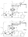
- FIG. 3 is a modification of in accordance with a second embodiment of the present invention in FIG. 1 represented electro-hydraulic axis, or the electro-hydraulic control arrangement 1 shown.
- the differences to the control arrangement 1 according to the embodiment described above are primarily carried out.
- the electro-hydraulic control arrangement 1 is provided instead of the pressure switching regulator 22 with a proportionally adjustable hydromechanical controller 30, which performs the control of the actuator 23 of the control pump 10.
- the hydromechanical pump controller 30 detects the output pressure of the variable displacement pump 10 via the control fluid line 21 and controls the actuator 23 in accordance with a pressure setpoint supplied to it on the signal line 8 as part of a pressure control.
- the system controller is implemented as a position or velocity controller 32.
- the main control loop thus contains, in addition to the position or speed controller 32, the subordinate engine control unit 14, the electric motor 12, the variable displacement pump 10, the piston-cylinder unit 2 and the displacement measuring system 6 and the signal line 7.
- a position setpoint or a speed setpoint is transmitted to the controller 32 the signal line 9 is supplied.
- the pending on the piston-cylinder unit 2 pressure can be controlled and limited largely independent of the speed of the electric motor 12 by the hydromechanical pump controller 30. If the pressure setpoint is not reached, the pump controller 30 keeps the actuator 23 at a maximum value and the speed or position control of the piston-cylinder unit 2 via the speed controller / position controller 32 of the main control loop.
- FIG. 4 Another variation of in FIG. 1 shown circuit is in the FIG. 4 specified.
- the electro-hydraulic control arrangement 1 shown therein for controlling the piston-cylinder unit 2 differs only slightly from the in FIG. 3 shown electro-hydraulic control arrangement 1 from.
- an electrical pressure sensor 16 is provided instead of the hydromechanical detection of the output pressure of the variable displacement pump 10. Via a signal line 47, the detected pressure is supplied to an electronic pump regulator 40. This receives a pressure setpoint on the signal line 8.
- the function of the electro-hydraulic control arrangement 1 according to FIG. 4 corresponds to the function of the electro-hydraulic control arrangement 1 according to FIG. 3 , with the difference that the return of the fluid pressure is not hydromechanical but electronic. This allows, for example, the use of versatile programmable digital controllers. Furthermore, a common integration of the speed controller / position controller 32, the motor control device 14 - at least its control logic - and the electronic pump controller 40 on a single microcontroller is conceivable.
- electro-hydraulic control arrangement 1 is not limited to the control of linear motors such as the piston-cylinder unit 2. Instead of the piston-cylinder unit 2, a rotary motor can also occur.
- Whose position is preferably detected by a rotation angle measuring system and the system controller 20 and the speed controller / position controller 32 supplied.
- an electro-hydraulic control arrangement with a hydraulic consumer controlled by the latter forms a main control loop.
- an auxiliary chain acts on the controlled system in order to optimize it in terms of noise reduction, energy consumption and a reduction in maximum torque.
- the Maustellkette can largely self-sufficient z.
- B. a predetermined Pressure threshold act on the controlled system.
- the main control loop compensates for the effect of disturbance compensation while improving the aforementioned properties.
- the Maustellkette can also be designed as a full pressure control loop to limit and regulate the pressure applied to the hydraulic consumer pressure in the context of a proportional pressure control.
Claims (6)
- Système de commande électro-hydraulique pour la commande d'un consommateur hydraulique (2), comportant une pompe à fluide (10) réglable en termes de son volume de refoulement, un entraînement (12, 14) électrique à vitesse de rotation variable accouplé à cette pompe à fluide pour entraîner cette dernière ainsi qu'un dispositif de détection de pression (16, 21) pour détecter une pression de fluide,
caractérisé en ce
qu'il est prévu un circuit de régulation principal (20, 14, 12, 10, 2, 6, 7 ; 32) dont l'organe de réglage est un organe de réglage de vitesse de rotation (14) de l'entraînement électrique (12, 14) et au moyen duquel la pression de fluide et/ou une grandeur de réglage subordonnée peu(ven)t être détectée(s) et régulée(s), conformément à une prescription de valeur de consigne fournie au circuit de régulation principal et
en ce qu'au moyen d'une chaîne de réglage secondaire (22 ; 30 ; 40), un organe de réglage de volume de refoulement (23) de la pompe à fluide (10) peut être commandé en fonction de la pression de fluide détectée et
en ce qu'un réglage de l'organe de réglage de volume de refoulement (23) peut être compensé au moyen de la chaîne de réglage secondaire (22) à la manière d'une régulation de grandeur perturbatrice au moyen du circuit de régulation principal (20, 14, 12, 10, 2, 6, 7). - Système de commande électro-hydraulique selon la revendication 1, caractérisé en ce qu'une régulation de pression/vitesse de substitution du consommateur (2) peut être effectuée au moyen du circuit de régulation principal (20, 14, 12, 10, 2, 6, 7).
- Système de commande électro-hydraulique selon la revendication 1 ou 2, caractérisé en ce que la chaîne de réglage secondaire (22) comporte un régulateur de commutation de pression, en particulier un régulateur à deux positions, au moyen duquel le volume de refoulement de la pompe à fluide (10) réglable peut être ajusté entre une valeur minimale prédéfinie et une valeur maximale en fonction d'un seuil de pression prédéfini (Ps).
- Système de commande électro-hydraulique selon la revendication 1 ou 2, caractérisé en ce que la chaîne de réglage secondaire (30 ; 40) comporte un régulateur de pression qui commande de manière proportionnelle l'organe de réglage de volume de refoulement (23) en fonction d'une valeur de consigne de pression pouvant être prédéfinie.
- Système de commande électro-hydraulique selon la revendication 3 ou 4, caractérisé en ce que la chaîne de réglage secondaire (30) comporte un asservissement hydromécanique (21) de la pression de charge.
- Système de commande électro-hydraulique selon la revendication 3 ou 4, caractérisé en ce que la chaîne de réglage secondaire (40) comporte un asservissement électronique (16, 47) de la pression de charge.
Applications Claiming Priority (2)
| Application Number | Priority Date | Filing Date | Title |
|---|---|---|---|
| DE102007007005.7A DE102007007005B4 (de) | 2007-02-08 | 2007-02-08 | Elektrohydraulische Steueranordnung |
| PCT/EP2007/011124 WO2008095525A1 (fr) | 2007-02-08 | 2007-12-18 | Système de contrôle électrohydraulique |
Publications (2)
| Publication Number | Publication Date |
|---|---|
| EP2121280A1 EP2121280A1 (fr) | 2009-11-25 |
| EP2121280B1 true EP2121280B1 (fr) | 2014-03-05 |
Family
ID=39321449
Family Applications (1)
| Application Number | Title | Priority Date | Filing Date |
|---|---|---|---|
| EP07856849.0A Active EP2121280B1 (fr) | 2007-02-08 | 2007-12-18 | Système de contrôle électrohydraulique |
Country Status (5)
| Country | Link |
|---|---|
| EP (1) | EP2121280B1 (fr) |
| JP (1) | JP5473607B2 (fr) |
| CN (1) | CN101594977B (fr) |
| DE (1) | DE102007007005B4 (fr) |
| WO (1) | WO2008095525A1 (fr) |
Families Citing this family (26)
| Publication number | Priority date | Publication date | Assignee | Title |
|---|---|---|---|---|
| DE102009059025A1 (de) * | 2009-12-18 | 2011-06-22 | Robert Bosch GmbH, 70469 | Verfahren zum Betrieb einer hydraulischen Arbeitsmaschine |
| DE102010010506A1 (de) * | 2010-03-06 | 2011-09-08 | Robert Bosch Gmbh | Elektrohydraulische Druckregelanordnung und Verfahren zur Druckregelung |
| AT508659B1 (de) | 2010-04-02 | 2011-03-15 | Engel Austria Gmbh | Hydraulische antriebseinheit für spritzgiessmaschine |
| DE102010027183A1 (de) | 2010-07-14 | 2012-01-19 | Robert Bosch Gmbh | Hydroaggregat |
| DE102010033346B3 (de) | 2010-08-04 | 2012-02-02 | Bucyrus Hex Gmbh | Verfahren zum Starten eines Elektromotors in einer hydraulisch betriebenen Arbeitsmaschine |
| DE102011108285A1 (de) | 2010-12-22 | 2012-06-28 | Robert Bosch Gmbh | Hydraulischer Antrieb |
| DE102011010218B4 (de) | 2011-02-03 | 2019-09-12 | Robert Bosch Gmbh | Verfahren zum Regeln des Drucks eines mittels einer drehzahlgeregelten Pumpe geförderten Fluids |
| FR2975774B1 (fr) | 2011-05-25 | 2014-01-17 | Eurocopter France | Procede de determination de l'effort statique developpe par une servocommande |
| CN102240770B (zh) * | 2011-06-22 | 2013-07-31 | 李俊 | 专用于高强度铆钉的铆接机及液压泵站 |
| US9000898B2 (en) * | 2012-08-16 | 2015-04-07 | Deere & Company | Electrohydraulic controller feedback system and method |
| DE102013005774B4 (de) * | 2013-04-05 | 2021-01-21 | Robert Bosch Gmbh | Nutzung einer von einem motor angetriebenen drehzahlvariablen hydraulikpumpe als hydrostatisches getriebe |
| FR3005703B1 (fr) * | 2013-05-14 | 2016-08-19 | Machine Smart | Systeme hydraulique a controle electronique de pression et de debit |
| CN104416894A (zh) * | 2013-08-20 | 2015-03-18 | 宁波弘讯科技股份有限公司 | 型坯壁厚控制系统及控制方法 |
| JP6253369B2 (ja) * | 2013-11-26 | 2017-12-27 | 第一電気株式会社 | ハイブリッドアクチュエータ |
| CN103821783B (zh) * | 2013-12-05 | 2016-02-03 | 中国第一汽车股份有限公司无锡油泵油嘴研究所 | 液压供油系统的恒压恒流装置 |
| DE102014226634B3 (de) * | 2014-12-19 | 2016-05-12 | Robert Bosch Gmbh | Verfahren zum Betreiben eines hydraulischen Antriebs, Recheneinheit, Computerprogramm und maschinenlesbares Speichermedium |
| DE102015221684A1 (de) | 2015-11-05 | 2017-05-11 | Robert Bosch Gmbh | Verfahren zum durcksensorlosen Stellen des Drucks eines mittels einer drehzahlgeregelten Pumpe geförderten Fluids |
| DE102015119108A1 (de) | 2015-11-06 | 2017-05-11 | Pleiger Maschinenbau Gmbh & Co. Kg | Verfahren und Vorrichtung zum Ansteuern einer hydraulisch betätigten Antriebseinheit einer Armatur |
| DE102016011778A1 (de) * | 2016-08-11 | 2018-02-15 | M A E Maschinen- Und Apparatebau Götzen Gmbh | Hydraulische, insbesondere druckspeicherlose, Antriebsanordnung für und mit einem Verbraucher, insbesondere für Pressen, sowie Verfahren zum Betreiben einer solchen hydraulischen Antriebsanordnung |
| DE102018202060A1 (de) | 2018-02-09 | 2019-08-14 | Robert Bosch Gmbh | Hydrostatische Anordnung |
| AT521016B1 (de) * | 2018-08-24 | 2019-10-15 | Engel Austria Gmbh | Verfahren und Vorrichtung zur Zustandsüberwachung einer Hydraulikpumpe |
| CN112460010B (zh) * | 2020-10-13 | 2023-06-09 | 中国煤炭科工集团太原研究院有限公司 | 一种矿用车载移动式乳化液泵站系统及控制方法 |
| AT524891B1 (de) * | 2021-03-29 | 2023-01-15 | Engel Austria Gmbh | Hydraulische Antriebsvorrichtung für eine Formgebungsmaschine |
| AT525047B1 (de) | 2021-06-23 | 2022-12-15 | Engel Austria Gmbh | Hydraulische Antriebsvorrichtung für eine Formgebungsmaschine |
| DE102022203051B3 (de) | 2022-03-29 | 2023-10-12 | Robert Bosch Gesellschaft mit beschränkter Haftung | Verfahren zum Betreiben einer drehzahlvariablen Pumpe |
| DE102022205233B4 (de) | 2022-05-25 | 2023-12-07 | Robert Bosch Gesellschaft mit beschränkter Haftung | Verfahren zum Betreiben eines Elektrohydraulikaggregats |
Family Cites Families (8)
| Publication number | Priority date | Publication date | Assignee | Title |
|---|---|---|---|---|
| DE3919823C3 (de) | 1989-06-14 | 1998-04-09 | Mannesmann Ag | Spritzgießmaschine mit hydraulischen Verbrauchern |
| US5052909A (en) | 1990-01-19 | 1991-10-01 | Cincinnati Milacron Inc. | Energy-conserving injection molding machine |
| DE4327313C2 (de) | 1993-08-13 | 2001-07-05 | Mannesmann Rexroth Ag | Verfahren zur Druckregelung einer hydrostatischen Maschine mit verstellbarem Fördervolumen |
| DE4335403C1 (de) | 1993-10-18 | 1994-12-15 | Karl Hehl | Hydraulikeinrichtung |
| CA2213457C (fr) | 1995-03-14 | 2005-05-24 | The Boeing Company | Systeme de commande de pompe hydraulique pour avion |
| DE19930648A1 (de) | 1999-07-02 | 2001-01-11 | Daimler Chrysler Ag | Elektrohydraulische Druckversorgung mit verstellbarer Pumpe und regelbarem elektrischem Antrieb |
| DE10110398A1 (de) | 2001-03-03 | 2002-09-26 | Mannesmann Rexroth Ag | Verfahren zur Regelung der Druckmittelzufuhr zu einem hydraulisch betätigten Aktor |
| JP4194868B2 (ja) * | 2003-03-28 | 2008-12-10 | 東京計器株式会社 | 液圧制御システム |
-
2007
- 2007-02-08 DE DE102007007005.7A patent/DE102007007005B4/de active Active
- 2007-12-18 JP JP2009548582A patent/JP5473607B2/ja not_active Expired - Fee Related
- 2007-12-18 WO PCT/EP2007/011124 patent/WO2008095525A1/fr active Application Filing
- 2007-12-18 EP EP07856849.0A patent/EP2121280B1/fr active Active
- 2007-12-18 CN CN200780050611.5A patent/CN101594977B/zh active Active
Also Published As
| Publication number | Publication date |
|---|---|
| CN101594977B (zh) | 2014-03-19 |
| CN101594977A (zh) | 2009-12-02 |
| JP5473607B2 (ja) | 2014-04-16 |
| JP2010517819A (ja) | 2010-05-27 |
| WO2008095525A1 (fr) | 2008-08-14 |
| DE102007007005B4 (de) | 2021-12-02 |
| DE102007007005A1 (de) | 2008-08-14 |
| EP2121280A1 (fr) | 2009-11-25 |
Similar Documents
| Publication | Publication Date | Title |
|---|---|---|
| EP2121280B1 (fr) | Système de contrôle électrohydraulique | |
| DE102008019501B4 (de) | Elektrohydraulische Steueranordnung | |
| EP2328747B1 (fr) | Système de commande hydraulique sans accumulateur de pression pour un consommateur et comprenant un consommateur, en particulier pour des presses hydrauliques, et procédé de commande hydraulique d'un consommateur sans utilisation d'un accumulateur de pression | |
| EP0782671B2 (fr) | DISPOSITIF POUR l'ENTREINEMENT CONTROLE D'AU MOINS UN ARBRE HYDRAULIQUE | |
| EP2357363B1 (fr) | Dispositif de commande pour une pompe volumétrique, système de pompes et procédé de fonctionnement de celui-ci | |
| EP1588057B1 (fr) | Systeme hydraulique pour entrainements lineaires commandes par des elements deplaceurs | |
| EP1714764A2 (fr) | Unité de fermeture de moule hydraulique | |
| DE10010670C2 (de) | Hydraulische Hubvorrichtung für batteriebetriebene Flurförderzeuge | |
| EP3839256B1 (fr) | Procédé de fonctionnement d'une pompe à débit variable à vitesse variable | |
| WO2002063170A1 (fr) | Systeme de pompage comprenant une pompe hydraulique, destine notamment a un systeme de direction | |
| EP1065379B1 (fr) | Alimentation en pression avec pompe à capacité variable et motorisation électrique réglable | |
| EP3497338A1 (fr) | Système d'entraînement hydraulique, en particulier sans accumulateur de pression, pour un consommateur et comprenant un consommateur, en particulier pour des presses, et procédé permettant de faire fonctionner un tel système d'entraînement hydraulique | |
| EP2655895B1 (fr) | Entraînement hydraulique | |
| EP2582507B1 (fr) | Procédé et dispositif pour le fonctionnement d'un axe entraîné dans une machine-outil | |
| EP1423249A2 (fr) | Dispositif de serrage electromecanique | |
| EP1355775B1 (fr) | Procede de regulation d'assistance hydraulique d'une commande electrique | |
| EP1930604B1 (fr) | Dispositif de commande hydraulique | |
| EP1460505B1 (fr) | Dispositif pour une régulation alternative de la pression et du débit d'un fluide hydraulique | |
| WO2016096565A1 (fr) | Circuit pour commander un consommateur rotatif | |
| EP2431166A1 (fr) | Système de commande pour presse de pliage | |
| DE3844399A1 (de) | Verstellpumpe fuer mehrere unabhaengig voneinander betaetigbare verbraucher | |
| WO2023041342A1 (fr) | Procédé pour un entraînement hydraulique, unité de commande, programme informatique et support d'enregistrement lisible par machine | |
| EP1445488A2 (fr) | Entraínement avec machine hydraulique | |
| CN107152434A (zh) | 一种实现流量调节的液压动力系统 |
Legal Events
| Date | Code | Title | Description |
|---|---|---|---|
| PUAI | Public reference made under article 153(3) epc to a published international application that has entered the european phase |
Free format text: ORIGINAL CODE: 0009012 |
|
| 17P | Request for examination filed |
Effective date: 20090908 |
|
| AK | Designated contracting states |
Kind code of ref document: A1 Designated state(s): AT BE BG CH CY CZ DE DK EE ES FI FR GB GR HU IE IS IT LI LT LU LV MC MT NL PL PT RO SE SI SK TR |
|
| 17Q | First examination report despatched |
Effective date: 20100128 |
|
| DAX | Request for extension of the european patent (deleted) | ||
| GRAP | Despatch of communication of intention to grant a patent |
Free format text: ORIGINAL CODE: EPIDOSNIGR1 |
|
| INTG | Intention to grant announced |
Effective date: 20131204 |
|
| GRAS | Grant fee paid |
Free format text: ORIGINAL CODE: EPIDOSNIGR3 |
|
| GRAA | (expected) grant |
Free format text: ORIGINAL CODE: 0009210 |
|
| AK | Designated contracting states |
Kind code of ref document: B1 Designated state(s): AT BE BG CH CY CZ DE DK EE ES FI FR GB GR HU IE IS IT LI LT LU LV MC MT NL PL PT RO SE SI SK TR |
|
| REG | Reference to a national code |
Ref country code: GB Ref legal event code: FG4D Free format text: NOT ENGLISH |
|
| REG | Reference to a national code |
Ref country code: CH Ref legal event code: EP |
|
| REG | Reference to a national code |
Ref country code: AT Ref legal event code: REF Ref document number: 654525 Country of ref document: AT Kind code of ref document: T Effective date: 20140315 |
|
| REG | Reference to a national code |
Ref country code: IE Ref legal event code: FG4D Free format text: LANGUAGE OF EP DOCUMENT: GERMAN |
|
| REG | Reference to a national code |
Ref country code: DE Ref legal event code: R096 Ref document number: 502007012834 Country of ref document: DE Effective date: 20140417 |
|
| REG | Reference to a national code |
Ref country code: NL Ref legal event code: VDEP Effective date: 20140305 |
|
| PG25 | Lapsed in a contracting state [announced via postgrant information from national office to epo] |
Ref country code: LT Free format text: LAPSE BECAUSE OF FAILURE TO SUBMIT A TRANSLATION OF THE DESCRIPTION OR TO PAY THE FEE WITHIN THE PRESCRIBED TIME-LIMIT Effective date: 20140305 |
|
| REG | Reference to a national code |
Ref country code: LT Ref legal event code: MG4D |
|
| PG25 | Lapsed in a contracting state [announced via postgrant information from national office to epo] |
Ref country code: CY Free format text: LAPSE BECAUSE OF FAILURE TO SUBMIT A TRANSLATION OF THE DESCRIPTION OR TO PAY THE FEE WITHIN THE PRESCRIBED TIME-LIMIT Effective date: 20140305 Ref country code: SE Free format text: LAPSE BECAUSE OF FAILURE TO SUBMIT A TRANSLATION OF THE DESCRIPTION OR TO PAY THE FEE WITHIN THE PRESCRIBED TIME-LIMIT Effective date: 20140305 Ref country code: FI Free format text: LAPSE BECAUSE OF FAILURE TO SUBMIT A TRANSLATION OF THE DESCRIPTION OR TO PAY THE FEE WITHIN THE PRESCRIBED TIME-LIMIT Effective date: 20140305 |
|
| PG25 | Lapsed in a contracting state [announced via postgrant information from national office to epo] |
Ref country code: LV Free format text: LAPSE BECAUSE OF FAILURE TO SUBMIT A TRANSLATION OF THE DESCRIPTION OR TO PAY THE FEE WITHIN THE PRESCRIBED TIME-LIMIT Effective date: 20140305 |
|
| PG25 | Lapsed in a contracting state [announced via postgrant information from national office to epo] |
Ref country code: NL Free format text: LAPSE BECAUSE OF FAILURE TO SUBMIT A TRANSLATION OF THE DESCRIPTION OR TO PAY THE FEE WITHIN THE PRESCRIBED TIME-LIMIT Effective date: 20140305 Ref country code: CZ Free format text: LAPSE BECAUSE OF FAILURE TO SUBMIT A TRANSLATION OF THE DESCRIPTION OR TO PAY THE FEE WITHIN THE PRESCRIBED TIME-LIMIT Effective date: 20140305 Ref country code: RO Free format text: LAPSE BECAUSE OF FAILURE TO SUBMIT A TRANSLATION OF THE DESCRIPTION OR TO PAY THE FEE WITHIN THE PRESCRIBED TIME-LIMIT Effective date: 20140305 Ref country code: IS Free format text: LAPSE BECAUSE OF FAILURE TO SUBMIT A TRANSLATION OF THE DESCRIPTION OR TO PAY THE FEE WITHIN THE PRESCRIBED TIME-LIMIT Effective date: 20140705 Ref country code: BG Free format text: LAPSE BECAUSE OF FAILURE TO SUBMIT A TRANSLATION OF THE DESCRIPTION OR TO PAY THE FEE WITHIN THE PRESCRIBED TIME-LIMIT Effective date: 20140605 Ref country code: EE Free format text: LAPSE BECAUSE OF FAILURE TO SUBMIT A TRANSLATION OF THE DESCRIPTION OR TO PAY THE FEE WITHIN THE PRESCRIBED TIME-LIMIT Effective date: 20140305 |
|
| PG25 | Lapsed in a contracting state [announced via postgrant information from national office to epo] |
Ref country code: ES Free format text: LAPSE BECAUSE OF FAILURE TO SUBMIT A TRANSLATION OF THE DESCRIPTION OR TO PAY THE FEE WITHIN THE PRESCRIBED TIME-LIMIT Effective date: 20140305 Ref country code: SK Free format text: LAPSE BECAUSE OF FAILURE TO SUBMIT A TRANSLATION OF THE DESCRIPTION OR TO PAY THE FEE WITHIN THE PRESCRIBED TIME-LIMIT Effective date: 20140305 Ref country code: PL Free format text: LAPSE BECAUSE OF FAILURE TO SUBMIT A TRANSLATION OF THE DESCRIPTION OR TO PAY THE FEE WITHIN THE PRESCRIBED TIME-LIMIT Effective date: 20140305 |
|
| REG | Reference to a national code |
Ref country code: DE Ref legal event code: R097 Ref document number: 502007012834 Country of ref document: DE |
|
| PG25 | Lapsed in a contracting state [announced via postgrant information from national office to epo] |
Ref country code: PT Free format text: LAPSE BECAUSE OF FAILURE TO SUBMIT A TRANSLATION OF THE DESCRIPTION OR TO PAY THE FEE WITHIN THE PRESCRIBED TIME-LIMIT Effective date: 20140707 |
|
| PLBE | No opposition filed within time limit |
Free format text: ORIGINAL CODE: 0009261 |
|
| STAA | Information on the status of an ep patent application or granted ep patent |
Free format text: STATUS: NO OPPOSITION FILED WITHIN TIME LIMIT |
|
| PG25 | Lapsed in a contracting state [announced via postgrant information from national office to epo] |
Ref country code: DK Free format text: LAPSE BECAUSE OF FAILURE TO SUBMIT A TRANSLATION OF THE DESCRIPTION OR TO PAY THE FEE WITHIN THE PRESCRIBED TIME-LIMIT Effective date: 20140305 |
|
| 26N | No opposition filed |
Effective date: 20141208 |
|
| REG | Reference to a national code |
Ref country code: DE Ref legal event code: R097 Ref document number: 502007012834 Country of ref document: DE Effective date: 20141208 |
|
| PG25 | Lapsed in a contracting state [announced via postgrant information from national office to epo] |
Ref country code: SI Free format text: LAPSE BECAUSE OF FAILURE TO SUBMIT A TRANSLATION OF THE DESCRIPTION OR TO PAY THE FEE WITHIN THE PRESCRIBED TIME-LIMIT Effective date: 20140305 |
|
| PG25 | Lapsed in a contracting state [announced via postgrant information from national office to epo] |
Ref country code: BE Free format text: LAPSE BECAUSE OF NON-PAYMENT OF DUE FEES Effective date: 20141231 |
|
| PG25 | Lapsed in a contracting state [announced via postgrant information from national office to epo] |
Ref country code: LU Free format text: LAPSE BECAUSE OF FAILURE TO SUBMIT A TRANSLATION OF THE DESCRIPTION OR TO PAY THE FEE WITHIN THE PRESCRIBED TIME-LIMIT Effective date: 20141218 |
|
| REG | Reference to a national code |
Ref country code: CH Ref legal event code: PL |
|
| GBPC | Gb: european patent ceased through non-payment of renewal fee |
Effective date: 20141218 |
|
| REG | Reference to a national code |
Ref country code: IE Ref legal event code: MM4A |
|
| REG | Reference to a national code |
Ref country code: FR Ref legal event code: ST Effective date: 20150831 |
|
| PG25 | Lapsed in a contracting state [announced via postgrant information from national office to epo] |
Ref country code: IE Free format text: LAPSE BECAUSE OF NON-PAYMENT OF DUE FEES Effective date: 20141218 Ref country code: LI Free format text: LAPSE BECAUSE OF NON-PAYMENT OF DUE FEES Effective date: 20141231 Ref country code: GB Free format text: LAPSE BECAUSE OF NON-PAYMENT OF DUE FEES Effective date: 20141218 Ref country code: CH Free format text: LAPSE BECAUSE OF NON-PAYMENT OF DUE FEES Effective date: 20141231 |
|
| PG25 | Lapsed in a contracting state [announced via postgrant information from national office to epo] |
Ref country code: FR Free format text: LAPSE BECAUSE OF NON-PAYMENT OF DUE FEES Effective date: 20141231 |
|
| REG | Reference to a national code |
Ref country code: AT Ref legal event code: MM01 Ref document number: 654525 Country of ref document: AT Kind code of ref document: T Effective date: 20141218 |
|
| PG25 | Lapsed in a contracting state [announced via postgrant information from national office to epo] |
Ref country code: AT Free format text: LAPSE BECAUSE OF NON-PAYMENT OF DUE FEES Effective date: 20141218 Ref country code: MC Free format text: LAPSE BECAUSE OF FAILURE TO SUBMIT A TRANSLATION OF THE DESCRIPTION OR TO PAY THE FEE WITHIN THE PRESCRIBED TIME-LIMIT Effective date: 20140305 |
|
| PG25 | Lapsed in a contracting state [announced via postgrant information from national office to epo] |
Ref country code: GR Free format text: LAPSE BECAUSE OF FAILURE TO SUBMIT A TRANSLATION OF THE DESCRIPTION OR TO PAY THE FEE WITHIN THE PRESCRIBED TIME-LIMIT Effective date: 20140606 |
|
| PG25 | Lapsed in a contracting state [announced via postgrant information from national office to epo] |
Ref country code: HU Free format text: LAPSE BECAUSE OF FAILURE TO SUBMIT A TRANSLATION OF THE DESCRIPTION OR TO PAY THE FEE WITHIN THE PRESCRIBED TIME-LIMIT; INVALID AB INITIO Effective date: 20071218 Ref country code: TR Free format text: LAPSE BECAUSE OF FAILURE TO SUBMIT A TRANSLATION OF THE DESCRIPTION OR TO PAY THE FEE WITHIN THE PRESCRIBED TIME-LIMIT Effective date: 20140305 Ref country code: MT Free format text: LAPSE BECAUSE OF FAILURE TO SUBMIT A TRANSLATION OF THE DESCRIPTION OR TO PAY THE FEE WITHIN THE PRESCRIBED TIME-LIMIT Effective date: 20140305 |
|
| PGFP | Annual fee paid to national office [announced via postgrant information from national office to epo] |
Ref country code: IT Payment date: 20221230 Year of fee payment: 16 Ref country code: DE Payment date: 20230223 Year of fee payment: 16 |