EP2120644B2 - Retracting mechanism for sliding elements - Google Patents
Retracting mechanism for sliding elements Download PDFInfo
- Publication number
- EP2120644B2 EP2120644B2 EP08707280.7A EP08707280A EP2120644B2 EP 2120644 B2 EP2120644 B2 EP 2120644B2 EP 08707280 A EP08707280 A EP 08707280A EP 2120644 B2 EP2120644 B2 EP 2120644B2
- Authority
- EP
- European Patent Office
- Prior art keywords
- coupling element
- bearing
- housing
- piston rod
- guided
- Prior art date
- Legal status (The legal status is an assumption and is not a legal conclusion. Google has not performed a legal analysis and makes no representation as to the accuracy of the status listed.)
- Not-in-force
Links
Images

Classifications
-
- E—FIXED CONSTRUCTIONS
- E05—LOCKS; KEYS; WINDOW OR DOOR FITTINGS; SAFES
- E05F—DEVICES FOR MOVING WINGS INTO OPEN OR CLOSED POSITION; CHECKS FOR WINGS; WING FITTINGS NOT OTHERWISE PROVIDED FOR, CONCERNED WITH THE FUNCTIONING OF THE WING
- E05F1/00—Closers or openers for wings, not otherwise provided for in this subclass
- E05F1/08—Closers or openers for wings, not otherwise provided for in this subclass spring-actuated, e.g. for horizontally sliding wings
- E05F1/16—Closers or openers for wings, not otherwise provided for in this subclass spring-actuated, e.g. for horizontally sliding wings for sliding wings
-
- A—HUMAN NECESSITIES
- A47—FURNITURE; DOMESTIC ARTICLES OR APPLIANCES; COFFEE MILLS; SPICE MILLS; SUCTION CLEANERS IN GENERAL
- A47B—TABLES; DESKS; OFFICE FURNITURE; CABINETS; DRAWERS; GENERAL DETAILS OF FURNITURE
- A47B88/00—Drawers for tables, cabinets or like furniture; Guides for drawers
- A47B88/40—Sliding drawers; Slides or guides therefor
- A47B88/453—Actuated drawers
- A47B88/46—Actuated drawers operated by mechanically-stored energy, e.g. by springs
- A47B88/467—Actuated drawers operated by mechanically-stored energy, e.g. by springs self-closing
-
- E—FIXED CONSTRUCTIONS
- E05—LOCKS; KEYS; WINDOW OR DOOR FITTINGS; SAFES
- E05F—DEVICES FOR MOVING WINGS INTO OPEN OR CLOSED POSITION; CHECKS FOR WINGS; WING FITTINGS NOT OTHERWISE PROVIDED FOR, CONCERNED WITH THE FUNCTIONING OF THE WING
- E05F3/00—Closers or openers with braking devices, e.g. checks; Construction of pneumatic or liquid braking devices
- E05F3/04—Closers or openers with braking devices, e.g. checks; Construction of pneumatic or liquid braking devices with liquid piston brakes
-
- E—FIXED CONSTRUCTIONS
- E05—LOCKS; KEYS; WINDOW OR DOOR FITTINGS; SAFES
- E05F—DEVICES FOR MOVING WINGS INTO OPEN OR CLOSED POSITION; CHECKS FOR WINGS; WING FITTINGS NOT OTHERWISE PROVIDED FOR, CONCERNED WITH THE FUNCTIONING OF THE WING
- E05F5/00—Braking devices, e.g. checks; Stops; Buffers
- E05F5/003—Braking devices, e.g. checks; Stops; Buffers for sliding wings
-
- E—FIXED CONSTRUCTIONS
- E05—LOCKS; KEYS; WINDOW OR DOOR FITTINGS; SAFES
- E05Y—INDEXING SCHEME RELATING TO HINGES OR OTHER SUSPENSION DEVICES FOR DOORS, WINDOWS OR WINGS AND DEVICES FOR MOVING WINGS INTO OPEN OR CLOSED POSITION, CHECKS FOR WINGS AND WING FITTINGS NOT OTHERWISE PROVIDED FOR, CONCERNED WITH THE FUNCTIONING OF THE WING
- E05Y2201/00—Constructional elements; Accessories therefore
- E05Y2201/40—Motors; Magnets; Springs; Weights; Accessories therefore
- E05Y2201/404—Motors; Magnets; Springs; Weights; Accessories therefore characterised by the function
- E05Y2201/41—Motors; Magnets; Springs; Weights; Accessories therefore characterised by the function for closing
- E05Y2201/412—Motors; Magnets; Springs; Weights; Accessories therefore characterised by the function for closing for the final closing movement
-
- E—FIXED CONSTRUCTIONS
- E05—LOCKS; KEYS; WINDOW OR DOOR FITTINGS; SAFES
- E05Y—INDEXING SCHEME RELATING TO HINGES OR OTHER SUSPENSION DEVICES FOR DOORS, WINDOWS OR WINGS AND DEVICES FOR MOVING WINGS INTO OPEN OR CLOSED POSITION, CHECKS FOR WINGS AND WING FITTINGS NOT OTHERWISE PROVIDED FOR, CONCERNED WITH THE FUNCTIONING OF THE WING
- E05Y2800/00—Details, accessories and auxiliary operations not otherwise provided for
- E05Y2800/20—Combinations of elements
- E05Y2800/21—Combinations of elements of identical elements, e.g. of identical compression springs
-
- E—FIXED CONSTRUCTIONS
- E05—LOCKS; KEYS; WINDOW OR DOOR FITTINGS; SAFES
- E05Y—INDEXING SCHEME RELATING TO HINGES OR OTHER SUSPENSION DEVICES FOR DOORS, WINDOWS OR WINGS AND DEVICES FOR MOVING WINGS INTO OPEN OR CLOSED POSITION, CHECKS FOR WINGS AND WING FITTINGS NOT OTHERWISE PROVIDED FOR, CONCERNED WITH THE FUNCTIONING OF THE WING
- E05Y2800/00—Details, accessories and auxiliary operations not otherwise provided for
- E05Y2800/20—Combinations of elements
- E05Y2800/23—Combinations of elements of elements of different categories
- E05Y2800/24—Combinations of elements of elements of different categories of springs and brakes
-
- E—FIXED CONSTRUCTIONS
- E05—LOCKS; KEYS; WINDOW OR DOOR FITTINGS; SAFES
- E05Y—INDEXING SCHEME RELATING TO HINGES OR OTHER SUSPENSION DEVICES FOR DOORS, WINDOWS OR WINGS AND DEVICES FOR MOVING WINGS INTO OPEN OR CLOSED POSITION, CHECKS FOR WINGS AND WING FITTINGS NOT OTHERWISE PROVIDED FOR, CONCERNED WITH THE FUNCTIONING OF THE WING
- E05Y2900/00—Application of doors, windows, wings or fittings thereof
- E05Y2900/20—Application of doors, windows, wings or fittings thereof for furnitures, e.g. cabinets
Definitions
- the invention relates to a retraction device, in particular for sliding elements, drawers or sliding doors, with a housing that accommodates a damping element, the damping element having a piston rod that receives a piston that is guided in an adjustable manner in a damping cylinder, the housing receiving a coupling element that in a guide link of the housing is adjustable between a pull-in position and a pull-out position, and wherein a tension spring is connected to the coupling element, which biases the coupling element in the pull-out position in the direction of the pull-in position.
- a feeding device is known.
- a damping element is accommodated in a housing, which has a damping cylinder in which a piston is adjustable against a damping fluid.
- a piston rod is coupled to the piston.
- the free end of the piston rod is attached to a guide slide.
- This is linearly adjustable in a guide slot of the housing.
- the guide carriage has a bearing shoulder which engages in a bearing seat of a coupling member in such a way that a pivot bearing is formed between these two parts. The coupling member can thus be pivoted into a folded-down position in the pull-out position relative to the guide carriage.
- pull-in device for drawers is from the WO 2005/011438 A1 known.
- This pull-in device has a jack housing in which a jack component is adjustable.
- the pawl component is connected to a tension spring, which biases it in a pull-out position in the direction of a pull-in position.
- a piston damper in the latch housing serves to dampen the adjustment of the latch component from the pull-out position to the pull-in position.
- a pawl component is adjustable by means of a tension spring.
- the train movement can be slowed down with a damper.
- Another feeding device is from the EP 1 700 985 A1 known. With this pull-in device, a sliding door can be moved spring-supported and damped into a closed position.
- the piston rod is connected directly to the coupling element by means of a pivot bearing.
- the guide carriage can be dispensed with. This significantly reduces the number of parts and assembly work.
- the force introduction point of the coupling element is placed closer to the piston rod, which results in a more stable structure with higher functional reliability.
- the pivot axis of the pivot bearing runs in the region of the guide link. In this way, bending forces that act on the piston rod, which can arise when the coupling element is folded down, are completely eliminated or at least kept very low.
- a particularly space-saving design can be realized for the pull-in device in that the coupling element is guided in an adjustable manner in the guide link by means of a bearing pin, that the bearing pin is linearly adjustable in a linear guide section of the guide link from the retracted position of the coupling element, and that the piston rod is aligned the linear guide section stands.
- the housing can be realized in an elongated construction with a low overall height or width. It is then easy to install, especially when space is limited in drawer guides. Because it is provided that the coupling element is adjustably guided in the guide link by means of the bearing pin, and because the pivot axis of the coupling element runs through the bearing pin, the coupling element can be guided in the guide link in a simple and space-saving manner.
- the bearing journal connects the coupling element to a bearing shoulder of the piston rod.
- the bearing journal can then be molded onto a separate component or directly onto the coupling element or onto the piston rod.
- a possible variant of the invention can be such that the coupling element has a spring holder to which the tension spring is directly coupled at a distance and eccentrically to the pivot axis of the pivot bearing. Because the point of action of the spring is assigned to the coupling element, a tilting moment can be generated. This ensures that the coupling element is reliably pulled into the folded position in the pull-out position.
- a tilt-stable and safe guidance of the coupling element can be achieved according to the invention with little effort in that the guide link has two slot guides which are excluded from two mutually parallel housing walls of the housing, that the coupling element is guided between these two housing walls and with a bearing pin in each of the slot guides is.
- a possible variant of the invention can be such that the coupling element carries at least one guide element which is guided in the guide link and swivels into a receptacle of the guide link in the folded-out pull-out position.
- the spring element is connected in one piece to the coupling element.
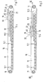
- the Figures 1 and 2 show a feed device 10 with a housing 12 which is provided at its longitudinal ends with fastening lugs 11.
- the attachment lugs 11 have screw receptacles.
- the housing 12 has two mutually parallel housing walls, which each run between the attachment lugs 11.
- Guide slots 12.2 in the form of slot guides are excluded from the fastening walls 12.4.
- the two guide links 12.2 are congruent. They have a linear guide section which merges into a widened receptacle 12.3.
- a coupling element 20 is adjustably accommodated in the housing 12.
- the design of the coupling element 20 designed as an injection molded part is shown in more detail in FIGS Figures 4 and 5 forth.
- the coupling element 20 has a base part 21.1, on which a holder 21 is formed in the form of a cantilever.
- the holder 21 carries a leaf spring-like spring element 23.
- the spring element 23 has at its free end a second stop 24 with a stop surface 24.1.
- the second stop 24 ends with a locking projection 24.2 which is extended in the direction of the holder 21.
- the second stop 24 bears against a recessed guide surface 26 of the holder 21, as is the case with the Figure 6 shows more clearly.
- undercut surfaces are provided on the second paragraph 24 and the holder 21, which form a guide 24.3 lying against one another. This guide 24.3 prevents a deflection of the second stop 24 perpendicular to the guide surface.
- the Figure 4 shows the spring element 23 in the articulated, the Figure 5 in the deflected position.
- the locking projection 24.2 limits the full spring-open.
- the spring element 23 springs completely open, so that the locking lug 24.2 is freely above the holder 21 in an extended position. This is the starting position in which the coupling element is removed from the injection molding tool and can therefore be produced without an undercut.
- the base part 21.1 also carries a first stop 25 which projects in the same direction as the second stop 24.
- the two stops 24, 25 are at a distance from each other, so that they delimit a receiving space between them.
- a damping element can be directly pivotally coupled to the coupling element 20.
- the damping element has one Damping cylinder 30, in which a piston against the pressure of a damping fluid (z. B. gaseous or liquid) can be moved.
- the piston carries a piston rod 32 which is led out of the damping cylinder.
- the piston rod 32 has a bearing boss 33 at its free end. This is pivotally held on a bearing receptacle 28 of the coupling element 20.
- the Figure 6 shows an example of the connection between the piston rod 32 and the coupling element 20. Accordingly, the bearing boss 33 and the bearing receptacle 28 have mutually aligned bores through which a bearing pin 29 in the form of a cylindrical pin is guided as a separate component.
- the bearing journal 29 is held non-positively either in the bearing projection 33 or in the bearing receptacle 28. This creates the pivot bearing, the pivot axis of which runs through the central longitudinal axis of the journal 29.
- a further variant of the invention, not shown in the drawings, can be such that the piston rod 32 and the coupling element 20 have molded-on components which engage in one another to form the pivot bearing.
- a bearing pin 29 can be molded onto the coupling element 20 (or the piston rod 32) and the piston rod 32 (or the coupling element 20) can be pushed onto this bearing pin 29 with a bore. Then the bearing journal 29 can be dispensed with as a separate component.
- the bearing pin 29 protrudes on both sides over the coupling element 20, the projecting sections engaging in the guide link 12.2.
- the coupling element 20 is thus stably guided between the two housing walls 12.4 and in the guide link 12.2.
- a spring holder 27 is arranged below the pivot bearing. This fixes the end of a tension spring 35, which is fixed at its other end to the housing 12. With the spaced arrangement of the connection point of the tension spring 35, a clockwise (according to Figure 5 ) Torque acting around the swivel axis of the swivel bearing.
- the damping cylinder 30 is inserted into a groove-shaped receiving compartment of the housing 12. In the axial direction, the damping cylinder 30 is fixed by means of projections 12.5 which protrude from the housing walls 12.5 and which engage in a circumferential groove 31 made in the damping cylinder 30.
- Openings 12.1 are made in the housing walls 12.4, which secure the damping cylinder 30 against lifting out.
- the Figure 1 shows the coupling element 20 in its initial position.
- the coupling element 20 in the pivot bearing is folded down relative to the piston rod 32 in such a way that guide elements 22 formed on both sides of the holders 21 of the coupling element 20 are held in the two receptacles 12.3 of the guide link 12.2.
- the tension spring 35 is in this position in its tensioning position and applies prestress to the coupling element 20 such that it is held in the folded-down position.
- the coupling element 20 in the position shown is ready to engage with a driver 40.
- the driver 40 can be fixed, for example on a furniture body, a sliding door frame and the retraction device can be attached to the sliding part to be moved (drawer, sliding door, etc.) (or vice versa).
- the driver 40 now moves towards the second stop 24, it moves onto the spring element 32 which is inclined in the direction of movement. He then deflects this perpendicular to the direction of movement "F" into the housing 12. When it has passed the second stop 24, the spring element 23 snaps back on and the driver 40 is in the correct position between the stops 24, 25 (see Figure 2 ).
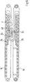
- the Figure 7 shows an arrangement as it can be used with heavy sliding parts (for example large sliding doors).
- FIG. 8 Another arrangement connected in parallel is in the Figure 8 shown. As this illustration shows, the drawing-in devices are arranged opposite one another, the housing walls 12.4 lying in pairs on one plane.
- the stops 24, 25 overlap Figure 6 shows, the retraction devices have two mutually parallel fastening planes E, with which they can be applied to fastening surfaces and fixed thereon.
- the central transverse plane M of the pull-in device is located centrally between the fastening planes E and parallel to these. As the Figure 6 can be seen, the stops 24, 25 do not project beyond this central transverse plane M, so that the in Figure 8 shown overlapped position of the stops 24, 25 is possible.
Description
Die Erfindung betrifft eine Einzugvorrichtung, insbesondere für Schiebelemente, Schubladen oder Schiebtüren mit einem Gehäuse, das ein Dämpfungselement aufnimmt, wobei das Dämpfungselement eine Kolbenstange aufweist, die einen in einem Dämpfungs-Zylinder verstellbar geführten Kolben aufnimmt, wobei das Gehäuse ein Koppelelement aufnimmt, das in einer Führungskulisse des Gehäuses zwischen einer Einzugposition und einer Auszugposition verstellbar ist, und wobei an das Koppelelement eine Spannfeder angeschlossen ist, die das Koppelelement in der Auszugposition in Richtung auf die Einzugposition vorspannt.The invention relates to a retraction device, in particular for sliding elements, drawers or sliding doors, with a housing that accommodates a damping element, the damping element having a piston rod that receives a piston that is guided in an adjustable manner in a damping cylinder, the housing receiving a coupling element that in a guide link of the housing is adjustable between a pull-in position and a pull-out position, and wherein a tension spring is connected to the coupling element, which biases the coupling element in the pull-out position in the direction of the pull-in position.
Aus der
Eine weitere Einzugvorrichtung für Schubladen ist aus der
Eine weitere Einzugvorrichtung ist in der
Eine weitere Einzugvorrichtung ist aus der
Es ist Aufgabe der Erfindung, eine Einzugvorrichtung der eingangs erwähnten Art zu schaffen, die mit geringem Teile- und Montageaufwand eine hohe Funktionssicherheit gewährleistet.It is an object of the invention to provide a drawing-in device of the type mentioned at the outset which ensures a high level of functional reliability with little outlay in terms of parts and assembly.
Diese Aufgabe wird mit den Merkmalen des Anspruches 1 gelöst. Die Kolbenstange ist erfindungsgemäß mittels eines Schwenklagers unmittelbar an das Koppelelement angeschlossen ist. Infolge der direkten Anbindung des Koppelelementes an die Kolbenstange kann auf den Führungsschlitten verzichtet werden. Damit verringert sich der Teile- und Montageaufwand erheblich. Darüber hinaus wird der Krafteinleitungspunkt des Koppelelementes dichter an die Kolbenstange gelegt, wodurch sich ein stabilerer Aufbau mit höherer Funktionssicherheit ergibt.This object is achieved with the features of claim 1. According to the invention, the piston rod is connected directly to the coupling element by means of a pivot bearing. As a result of the direct connection of the coupling element to the piston rod, the guide carriage can be dispensed with. This significantly reduces the number of parts and assembly work. In addition, the force introduction point of the coupling element is placed closer to the piston rod, which results in a more stable structure with higher functional reliability.
Erfindungsgemäß ist es vorgesehen, dass die Schwenkachse des Schwenklagers im Bereich der Führungskulisse verläuft. Auf diese Weise werden Biegekräfte, die auf die Kolbenstange wirken, welche beim Abklappen des Koppelelementes entstehen können, vollständig eliminiert oder zumindest sehr gering gehalten.According to the invention, it is provided that the pivot axis of the pivot bearing runs in the region of the guide link. In this way, bending forces that act on the piston rod, which can arise when the coupling element is folded down, are completely eliminated or at least kept very low.
Ein besonders Platz sparender Aufbau lässt sich für die Einzugvorrichtung dadurch verwirklichen, dass das Koppelelement mittels eines Lagerzapfens in der Führungskulisse verstellbar geführt ist, dass der Lagerzapfen aus der Einzugposition des Koppelelementes linear in einem Linearführungsabschnitt der Führungskulisse verstellbar ist, und dass die Kolbenstange in Flucht zu dem Linearführungsabschnitt steht. Auf diese Weise lässt sich das Gehäuse in lang gestreckter Bauweise mit einer geringen Bauhöhe bzw. -breite realisieren. Sie ist dann, insbesondere bei beengten Platzverhältnissen in Schubladenführungen leicht einbaubar. Weil vorgesehen ist, dass das Koppelelement mittels des Lagerzapfens in der Führungskulisse verstellbar geführt ist, und weil die Schwenkachse des Koppelelementes durch den Lagerzapfen verläuft, lässt sich einfach und Platz sparend die Führung des Koppelelementes in der Führungskulisse verwirklichen.A particularly space-saving design can be realized for the pull-in device in that the coupling element is guided in an adjustable manner in the guide link by means of a bearing pin, that the bearing pin is linearly adjustable in a linear guide section of the guide link from the retracted position of the coupling element, and that the piston rod is aligned the linear guide section stands. In this way, the housing can be realized in an elongated construction with a low overall height or width. It is then easy to install, especially when space is limited in drawer guides. Because it is provided that the coupling element is adjustably guided in the guide link by means of the bearing pin, and because the pivot axis of the coupling element runs through the bearing pin, the coupling element can be guided in the guide link in a simple and space-saving manner.
Hierbei kann eine weitere Reduzierung des Teileaufwandes dann verwirklicht werden, wenn vorgesehen ist, dass der Lagerzapfen das Koppelelement mit einem Lageransatz der Kolbenstange verbindet. Der Lagerzapfen kann dann ein separates Bauteil oder direkt an das Koppelelement oder an die Kolbenstange angeformt sein. Eine mögliche Erfindungsvariante kann dergestalt sein, dass das Koppelelement einen Federhalter aufweist, an den die Spannfeder im Abstand und exzentrisch zu der Schwenkachse des Schwenklagers unmittelbar angekoppelt ist. Dadurch, dass der Einwirkpunkt der Feder dem Koppelelement zugeordnet ist, kann ein Kippmoment erzeugt werden. Dieses stellt sicher, dass das Koppelelement in der Auszugposition zuverlässig in die abgeklappte Stellung gezogen wird.A further reduction in the number of parts can be achieved if it is provided that the bearing journal connects the coupling element to a bearing shoulder of the piston rod. The bearing journal can then be molded onto a separate component or directly onto the coupling element or onto the piston rod. A possible variant of the invention can be such that the coupling element has a spring holder to which the tension spring is directly coupled at a distance and eccentrically to the pivot axis of the pivot bearing. Because the point of action of the spring is assigned to the coupling element, a tilting moment can be generated. This ensures that the coupling element is reliably pulled into the folded position in the pull-out position.
Eine kippstabile und sichere Führung des Koppelelementes lässt sich erfindungsgemäß mit geringem Aufwand dadurch erreichen, dass die Führungskulisse zwei Schlitzführungen aufweist, die aus zwei zueinander parallelen Gehäusewänden des Gehäuses ausgenommen sind, dass das Koppelelement zwischen diesen beiden Gehäusewänden und mit je einem Lagerzapfen in den Schlitzführungen geführt ist.A tilt-stable and safe guidance of the coupling element can be achieved according to the invention with little effort in that the guide link has two slot guides which are excluded from two mutually parallel housing walls of the housing, that the coupling element is guided between these two housing walls and with a bearing pin in each of the slot guides is.
Eine mögliche Erfindungsvariante kann dergestalt sein, dass das Koppelelement wenigstens ein Führungselement trägt, das in der Führungskulisse geführt ist und in der abgeklappten Auszugposition in einer Aufnahme der Führungskulisse einschwenkt. Eine Reduzierung des Teileaufwandes ist dadurch möglich, dass das Federelement einteilig mit dem Koppelelement verbunden ist.A possible variant of the invention can be such that the coupling element carries at least one guide element which is guided in the guide link and swivels into a receptacle of the guide link in the folded-out pull-out position. A reduction in the number of parts is possible in that the spring element is connected in one piece to the coupling element.
Die Erfindung wird im Folgenden anhand eines in den Zeichnungen dargestellten Ausführungsbeispieles näher erläutert. Es zeigen:
- Figur 1
- eine Einzugvorrichtung in Seitenansicht mit einem Koppelelement in Auszugposition;
- Figur 2
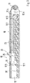
- die Darstellung gemäß
Figur 1 jedoch mit dem Koppelelement in Einzugposition; - Figur 3
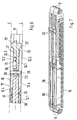
- den Einzugdämpfer gemäß
Figur 2 in einer perspektivischen Teildarstellung; - Figur 4
- in perspektivischer Ansicht das Koppelelement mit einem angeschlossenen Dämpferelement und einer Spannfeder;
- Figur 5
- die Darstellung gemäß
Figur 4 in einer veränderten Funktionsstellung; - Figur 6
- einen Horizontalschnitt durch die Einzugvorrichtung entlang dem in
Figur 2 gezeigten Schnittverlauf VI-VI in Teildarstellung; - Figur 7
- in perspektivischer Darstellung zwei aneinander gereihte Einzugvorrichtungen und
- Figur 8
- zwei einander gegenüberliegend angeordnete Einzugvorrichtungen in Draufsicht.
- Figure 1
- a feed device in side view with a coupling element in the pull-out position;
- Figure 2
- the representation according to
Figure 1 however with the coupling element in the retracted position; - Figure 3
- the feed damper according to
Figure 2 in a partial perspective view; - Figure 4
- in perspective view, the coupling element with a connected damper element and a tension spring;
- Figure 5
- the representation according to
Figure 4 in a changed functional position; - Figure 6
- a horizontal section through the feeder along the in
Figure 2 shown section VI-VI in partial representation; - Figure 7
- in a perspective view two feeders lined up and
- Figure 8
- top view of two opposing feeders.
Die
Der Halter 21 trägt ein blattfederartig ausgebildetes Federelement 23. Das Federelement 23 weist an seinem freien Ende einen zweiten Anschlag 24 mit einer Anschlagfläche 24.1 auf. Der zweite Anschlag 24 schließt mit einem in Richtung auf den Halter 21 ausgestellten Sperransatz 24.2 ab. Der zweite Anschlag 24 liegt an einer zurückversetzten Führungsfläche 26 des Halters 21 an, wie dies die
In der ausgelenkten Stellung begrenzt der Sperransatz 24.2 das vollständige Auffedern. Wenn der Sperransatz 24.2 außer Eingriff mit dem Halter 21 gebracht wird, federt das Federelement 23 vollständig auf, so dass der Sperransatz 24.2 frei über dem Halter 21 in einer gestreckten Lage steht. Dies ist die Ausgangsstellung in der das Koppelelement aus dem Spritzgusswerkzeug entnommen wird und somit ohne Hinterschnitt herstellbar ist.In the deflected position, the locking projection 24.2 limits the full spring-open. When the locking lug 24.2 is brought out of engagement with the
Das Basisteil 21.1 trägt auch einen ersten Anschlag 25, der in gleiche Richtung wie der zweite Anschlag 24 vorsteht. Wie die
An das Koppelelement 20 kann ein Dämpfungselement unmittelbar schwenkbar angekoppelt werden. Das Dämpfungselement weist einen Dämpfungszylinder 30 auf, in dem ein Kolben gegen den Druck eines Dämpfungsfluides (z. B. gasförmig oder flüssig) verschoben werden kann. Der Kolben trägt eine Kolbenstange 32, die aus dem Dämpfungszylinder herausgeführt ist.A damping element can be directly pivotally coupled to the
Die Kolbenstange 32 weist an ihrem freien Ende einen Lageransatz 33 auf. Dieser ist an einer Lageraufnahme 28 des Koppelelementes 20 schwenkbar gehalten. Die
Beispielsweise kann ein Lagerzapfen 29 an das Koppelelement 20 (oder die Kolbenstange 32) angeformt und die Kolbenstange 32 (oder das Koppelelement 20) mit einer Bohrung auf diesen Lagerzapfen 29 aufgeschoben sein. Dann kann auf den Lagerzapfen 29 als separates Bauteil verzichtet werden.For example, a bearing
Wie die
Wie die
Wie die
Dabei ist der Dämpfungszylinder 30 in ein nutförmiges Aufnahmefach des Gehäuses 12 eingelegt. In Achsrichtung wird der Dämpfungszylinder 30 mittels von den Gehäusewänden 12.5 abstehenden Vorsprüngen 12.5 fixiert, die in eine in den Dämpfungszylinder 30 eingebrachte Umfangsnut 31 eingreifen.The damping
In die Gehäusewände 12.4 sind Durchbrüche 12.1 eingebracht, die den Dämpfungszylinder 30 gegen Ausheben sichern.Openings 12.1 are made in the housing walls 12.4, which secure the damping
Die
Wenn der Mitnehmer 40 auf den ersten Anschlag 25 in Richtung der Bewegung des Schiebeteils in die Schließstellung auftrifft (siehe "F" in
Der Aufprall des Mitnehmers 40 auf den ersten Anschlag 25 wird von dem Dämpfungselement (Dämpfungszylinder 30) abgefedert. Und somit wird das Schiebeteil mit Hilfe der Kraft der Spannfeder 35 in seine Schließstellung gezogen. Beim Öffnen des Schließteils wird das Koppelelement 20 von dem am zweiten Anschlag 24 anliegenden Mitnehmer 25 gezogen und in die in
Wenn nun der Mitnehmer 40 sich auf den zweiten Anschlag 24 zubewegt, fährt er auf das in Bewegungsrichtung schräg gestellte Federelement 32 auf. Er lenkt dieses dann senkrecht zur Bewegungsrichtung "F" in das Gehäuse 12 hinein aus. Wenn er den zweiten Anschlag 24 passiert hat, schnappt das Federelement 23 wieder auf und der Mitnehmer 40 befindet sich lagerichtig zwischen den Anschlägen 24, 25 (siehe
Die
Eine weitere parallel geschaltete Anordnung ist in der
Dabei überlappen die Anschläge 24, 25. Wie die
Claims (6)
- Retraction device, in particular for sliding elements, drawers or sliding doors, comprising a housing (12) which receives a damping element, wherein the damping element comprises a piston rod (32) to receive a piston which is guided to be displaceable in a damping cylinder (30), wherein the housing (12) receives a coupling element (20) which is displaceable between a retracted position and an extended position, wherein a tension spring (35) is connected to the coupling element (20) to tension the coupling element (20) in the extended position in the direction of the retracted position, and wherein the piston rod (32) is connected directly to the coupling element (20) via a pivot bearing (29), wherein the coupling element (20) is guided in a guide slot (12.2) of the housing (12), and wherein the pivot axis of the pivot bearing extends in the region of the guide slot (12.2), wherein the guide slot (12.2) comprises two slot guides which are cut out from two parallel housing walls (12.4) of the housing (12),- wherein the coupling element (20) is guided between these two housing walls (12.4) in the slot guides each with a bearing journal (29),- wherein the pivot axis of the pivot bearing runs through the bearing journal (29),- wherein the coupling element (20) comprises a first and a second stop (25 and 24) spaced apart from each other,- wherein the second stop (24) is supported by a spring element (23),- wherein the spring element (23) may be deflected in an adjustment direction extending substantially in the pivoting direction of the coupling element (20).
- Retraction device according to claim 1,
characterized in that- the coupling element (20) is adjustably guided in the guide slot (12.2) by means of a bearing journal (29)- the bearing journal (29) may be linearly adjusted from the retracted position of the coupling element (20) in a linear guide section of the guide slot (12.2), and- the piston rod (32) is aligned with the linear guide section. - Retraction device according to claim 1 or 2,
characterized in that
the bearing journal (29) connects the coupling element (20) to a bearing shoulder (33) of the piston rod. - Retraction device according to one of claims 1 to 3,
characterized in that
the coupling element (20) comprises a spring holder (27), to which the tension spring (35) is directly coupled at a distance and eccentrically to the pivot axis of the pivot bearing. - Retraction device according to one of the claims 1 to 4,
characterized in that
the coupling element (20) carries at least one guide element (22) which is guided in the guide slot (12.2) and pivots into a receptacle (12.3) of the guide slot (12.2) in the folded-out extended position. - Retraction device according to one of the claims 1 to 5,
characterized in that
the spring element (23) is integrally connected with the coupling element (20).
Priority Applications (3)
| Application Number | Priority Date | Filing Date | Title |
|---|---|---|---|
| PL08707280T PL2120644T5 (en) | 2007-02-20 | 2008-01-25 | Retracting mechanism for sliding elements |
| EP11173255.8A EP2377430B1 (en) | 2007-02-20 | 2008-01-25 | Pulling device for sliding elements |
| EP20150642.5A EP3666119A1 (en) | 2007-02-20 | 2008-01-25 | Retraction device for sliding elements |
Applications Claiming Priority (2)
| Application Number | Priority Date | Filing Date | Title |
|---|---|---|---|
| DE102007008688A DE102007008688A1 (en) | 2007-02-20 | 2007-02-20 | Feeding device for sliding elements |
| PCT/EP2008/000570 WO2008101582A2 (en) | 2007-02-20 | 2008-01-25 | Retracting mechanism for sliding elements |
Related Child Applications (4)
| Application Number | Title | Priority Date | Filing Date |
|---|---|---|---|
| EP20150642.5A Division EP3666119A1 (en) | 2007-02-20 | 2008-01-25 | Retraction device for sliding elements |
| EP20150642.5A Division-Into EP3666119A1 (en) | 2007-02-20 | 2008-01-25 | Retraction device for sliding elements |
| EP11173255.8A Division EP2377430B1 (en) | 2007-02-20 | 2008-01-25 | Pulling device for sliding elements |
| EP11173255.8A Division-Into EP2377430B1 (en) | 2007-02-20 | 2008-01-25 | Pulling device for sliding elements |
Publications (3)
| Publication Number | Publication Date |
|---|---|
| EP2120644A2 EP2120644A2 (en) | 2009-11-25 |
| EP2120644B1 EP2120644B1 (en) | 2017-06-21 |
| EP2120644B2 true EP2120644B2 (en) | 2020-06-10 |
Family
ID=39474044
Family Applications (3)
| Application Number | Title | Priority Date | Filing Date |
|---|---|---|---|
| EP20150642.5A Withdrawn EP3666119A1 (en) | 2007-02-20 | 2008-01-25 | Retraction device for sliding elements |
| EP08707280.7A Not-in-force EP2120644B2 (en) | 2007-02-20 | 2008-01-25 | Retracting mechanism for sliding elements |
| EP11173255.8A Active EP2377430B1 (en) | 2007-02-20 | 2008-01-25 | Pulling device for sliding elements |
Family Applications Before (1)
| Application Number | Title | Priority Date | Filing Date |
|---|---|---|---|
| EP20150642.5A Withdrawn EP3666119A1 (en) | 2007-02-20 | 2008-01-25 | Retraction device for sliding elements |
Family Applications After (1)
| Application Number | Title | Priority Date | Filing Date |
|---|---|---|---|
| EP11173255.8A Active EP2377430B1 (en) | 2007-02-20 | 2008-01-25 | Pulling device for sliding elements |
Country Status (7)
| Country | Link |
|---|---|
| EP (3) | EP3666119A1 (en) |
| JP (1) | JP5096499B2 (en) |
| CZ (2) | CZ24790U1 (en) |
| DE (3) | DE202007019190U1 (en) |
| ES (2) | ES2815929T3 (en) |
| PL (1) | PL2120644T5 (en) |
| WO (1) | WO2008101582A2 (en) |
Families Citing this family (21)
| Publication number | Priority date | Publication date | Assignee | Title |
|---|---|---|---|---|
| DE102008051360A1 (en) | 2008-10-15 | 2010-05-12 | Karl Simon Gmbh & Co. Kg | retraction device |
| DE202008016409U1 (en) * | 2008-12-13 | 2010-04-22 | Paul Hettich Gmbh & Co. Kg | Self-closing device and pullout guide |
| EP2413741B1 (en) * | 2009-04-04 | 2015-07-08 | KARL SIMON GmbH & Co. KG | Retracting device |
| DE102009021202B4 (en) | 2009-04-04 | 2014-09-25 | Karl Simon Gmbh & Co. Kg | retraction device |
| DE202009009566U1 (en) | 2009-04-04 | 2009-11-19 | Karl Simon Gmbh & Co. Kg | retraction device |
| DE102009020994B4 (en) | 2009-05-12 | 2017-08-10 | Karl Simon Gmbh & Co. Kg | retraction device |
| DE202009006855U1 (en) | 2009-05-12 | 2010-09-30 | Karl Simon Gmbh & Co. Kg | retraction device |
| DE202009014685U1 (en) | 2009-10-14 | 2010-06-17 | Karl Simon Gmbh & Co. Kg | sliding arrangement |
| IT1397672B1 (en) * | 2010-01-22 | 2013-01-18 | Eclisse Srl | HIDDEN SLIDING DOOR, WITH STROKE CONTROL AND SELF-WHEEL DEVICES FOR THE DOOR PANEL. |
| DE202010008079U1 (en) | 2010-07-14 | 2010-09-09 | Anton Schneider Gmbh & Co Kg | Pull-out guide for drawers |
| DE102010043422B4 (en) | 2010-11-04 | 2024-04-04 | Schock Metallwerk Gmbh | Fastening device |
| DE102011050621A1 (en) | 2011-05-24 | 2012-11-29 | Karl Simon Gmbh & Co. Kg | retraction device |
| ES2474290B1 (en) * | 2013-01-08 | 2015-01-02 | Industrias Auxiliares, S.A. (Indaux) | SELF-CLOSURE DEVICE FOR SLIDING MOBILE PARTS |
| DE102013104886A1 (en) | 2013-05-13 | 2014-11-13 | Karl Simon Gmbh & Co. Kg | sliding arrangement |
| DE102015003414B3 (en) * | 2015-03-17 | 2016-06-16 | Günther Zimmer | Combined acceleration and deceleration device with overload protection |
| CN105534092A (en) * | 2016-01-21 | 2016-05-04 | 泛亚电子工业(无锡)有限公司 | Sliding rail self-locking damping mechanism for drawer |
| DE102016107919A1 (en) * | 2016-04-28 | 2017-11-02 | Paul Hettich Gmbh & Co. Kg | Discharge device for a movable furniture part, furniture part and method for opening and closing a movable furniture part |
| CN106121431B (en) * | 2016-08-30 | 2017-08-25 | 中山市佰迪克五金制品有限公司 | A kind of combination buffer system of |
| DE102018008207B4 (en) | 2018-10-14 | 2023-11-09 | Günther Zimmer | Deceleration device with multi-part driving element |
| AT523429B1 (en) * | 2020-06-10 | 2021-08-15 | Fulterer Ag & Co Kg | Self-retracting device |
| CN112116848B (en) * | 2020-07-20 | 2023-01-31 | 浙江科技学院 | University student's innovation venture education teaching equipment |
Citations (12)
| Publication number | Priority date | Publication date | Assignee | Title |
|---|---|---|---|---|
| DE9013161U1 (en) † | 1990-09-17 | 1990-11-22 | Paul Hettich Gmbh & Co, 4983 Kirchlengern, De | |
| DE9420920U1 (en) † | 1994-12-30 | 1995-02-09 | Klaus Brummernhenrich Kunststo | Drawer pull-in fitting |
| AT401716B (en) † | 1990-12-14 | 1996-11-25 | Blum Gmbh Julius | Drawer with closing devices |
| US20030234604A1 (en) † | 2002-06-20 | 2003-12-25 | Nan Juen International Co., Ltd. | Buffer and return device for a slide rail in a drawer |
| EP1479317A1 (en) † | 2003-05-22 | 2004-11-24 | Hettich-Heinze GmbH & Co. KG | Damping and closure device |
| DE202004005322U1 (en) † | 2003-11-05 | 2005-03-24 | Alfit Ag Goetzis | Automatic retraction system for drawer within a surrounding cabinet has progressive system of spring action |
| DE202005004336U1 (en) † | 2005-03-17 | 2005-06-23 | Hettich-Heinze Gmbh & Co. Kg | Self-closing device for sliding doors, folding doors or similar furniture items has an energy storage component that is tensioned during door opening and then acts on the door to close it via an adapter and a cam on the door |
| JP2005230468A (en) † | 2004-02-23 | 2005-09-02 | Fuji Latex Kk | Drawer guide, and shock absorber |
| EP1658785A1 (en) † | 2004-11-23 | 2006-05-24 | Vauth-Sagel Holding GmbH & Co. KG | Closing aid for a drawer |
| JP2006308044A (en) † | 2005-05-02 | 2006-11-09 | Nifco Inc | Damper device and drawer device |
| EP1743550A1 (en) † | 2005-07-15 | 2007-01-17 | Alfit AG | Displacement device for furniture extensions, in particular drawers |
| DE202005015529U1 (en) † | 2005-10-04 | 2007-02-15 | Paul Hettich Gmbh & Co. Kg | retraction device |
Family Cites Families (6)
| Publication number | Priority date | Publication date | Assignee | Title |
|---|---|---|---|---|
| DE4020277C2 (en) * | 1990-06-26 | 1995-02-09 | Lautenschlaeger Mepla Werke | Automatic retraction for drawer pull-out guides |
| DE20311795U1 (en) * | 2003-07-31 | 2004-11-18 | Alfit Ag | Drawer pull-out guide with automatic retraction with integrated damping |
| GB0328262D0 (en) * | 2003-12-05 | 2004-01-07 | Titus Int Plc | Improvements in movement controls |
| DE202004006410U1 (en) * | 2004-04-20 | 2005-09-01 | Alfit Ag | Automatic catch with damping device for drawer pull-out guides |
| US7537296B2 (en) * | 2004-11-05 | 2009-05-26 | Accuride International, Inc. | Dampened movement mechanism and slide incorporating the same |
| DE102006058639B4 (en) * | 2006-12-11 | 2008-08-14 | Zimmer, Günther | Combined deceleration and acceleration device |
-
2007
- 2007-02-20 DE DE202007019190U patent/DE202007019190U1/en not_active Expired - Lifetime
- 2007-02-20 DE DE102007008688A patent/DE102007008688A1/en not_active Ceased
-
2008
- 2008-01-25 WO PCT/EP2008/000570 patent/WO2008101582A2/en active Application Filing
- 2008-01-25 CZ CZ201125011U patent/CZ24790U1/en not_active IP Right Cessation
- 2008-01-25 EP EP20150642.5A patent/EP3666119A1/en not_active Withdrawn
- 2008-01-25 ES ES11173255T patent/ES2815929T3/en active Active
- 2008-01-25 ES ES08707280T patent/ES2639851T5/en active Active
- 2008-01-25 CZ CZ201125012U patent/CZ24243U1/en not_active IP Right Cessation
- 2008-01-25 EP EP08707280.7A patent/EP2120644B2/en not_active Not-in-force
- 2008-01-25 DE DE202008018154U patent/DE202008018154U1/en not_active Expired - Lifetime
- 2008-01-25 PL PL08707280T patent/PL2120644T5/en unknown
- 2008-01-25 EP EP11173255.8A patent/EP2377430B1/en active Active
- 2008-01-25 JP JP2009549788A patent/JP5096499B2/en not_active Expired - Fee Related
Patent Citations (12)
| Publication number | Priority date | Publication date | Assignee | Title |
|---|---|---|---|---|
| DE9013161U1 (en) † | 1990-09-17 | 1990-11-22 | Paul Hettich Gmbh & Co, 4983 Kirchlengern, De | |
| AT401716B (en) † | 1990-12-14 | 1996-11-25 | Blum Gmbh Julius | Drawer with closing devices |
| DE9420920U1 (en) † | 1994-12-30 | 1995-02-09 | Klaus Brummernhenrich Kunststo | Drawer pull-in fitting |
| US20030234604A1 (en) † | 2002-06-20 | 2003-12-25 | Nan Juen International Co., Ltd. | Buffer and return device for a slide rail in a drawer |
| EP1479317A1 (en) † | 2003-05-22 | 2004-11-24 | Hettich-Heinze GmbH & Co. KG | Damping and closure device |
| DE202004005322U1 (en) † | 2003-11-05 | 2005-03-24 | Alfit Ag Goetzis | Automatic retraction system for drawer within a surrounding cabinet has progressive system of spring action |
| JP2005230468A (en) † | 2004-02-23 | 2005-09-02 | Fuji Latex Kk | Drawer guide, and shock absorber |
| EP1658785A1 (en) † | 2004-11-23 | 2006-05-24 | Vauth-Sagel Holding GmbH & Co. KG | Closing aid for a drawer |
| DE202005004336U1 (en) † | 2005-03-17 | 2005-06-23 | Hettich-Heinze Gmbh & Co. Kg | Self-closing device for sliding doors, folding doors or similar furniture items has an energy storage component that is tensioned during door opening and then acts on the door to close it via an adapter and a cam on the door |
| JP2006308044A (en) † | 2005-05-02 | 2006-11-09 | Nifco Inc | Damper device and drawer device |
| EP1743550A1 (en) † | 2005-07-15 | 2007-01-17 | Alfit AG | Displacement device for furniture extensions, in particular drawers |
| DE202005015529U1 (en) † | 2005-10-04 | 2007-02-15 | Paul Hettich Gmbh & Co. Kg | retraction device |
Also Published As
| Publication number | Publication date |
|---|---|
| CZ24243U1 (en) | 2012-09-03 |
| JP2010519434A (en) | 2010-06-03 |
| ES2639851T5 (en) | 2021-03-29 |
| EP2377430A1 (en) | 2011-10-19 |
| JP5096499B2 (en) | 2012-12-12 |
| ES2639851T3 (en) | 2017-10-30 |
| EP2377430B1 (en) | 2020-06-17 |
| CZ24790U1 (en) | 2013-01-10 |
| PL2120644T3 (en) | 2017-12-29 |
| EP2120644B1 (en) | 2017-06-21 |
| ES2815929T3 (en) | 2021-03-31 |
| WO2008101582A2 (en) | 2008-08-28 |
| EP3666119A1 (en) | 2020-06-17 |
| DE102007008688A1 (en) | 2008-08-21 |
| DE202007019190U1 (en) | 2011-02-10 |
| PL2120644T5 (en) | 2020-11-16 |
| DE202008018154U1 (en) | 2011-12-08 |
| WO2008101582A3 (en) | 2008-11-20 |
| EP2120644A2 (en) | 2009-11-25 |
Similar Documents
| Publication | Publication Date | Title |
|---|---|---|
| EP2120644B2 (en) | Retracting mechanism for sliding elements | |
| EP1907657B1 (en) | Damping element | |
| EP1709270A1 (en) | Clip fixing element for the assembly of fixture devices such as locks, hinge parts and handles in openings in a thin wall | |
| EP2353445B2 (en) | Slide for retracting parts of furniture | |
| EP2439363B1 (en) | Panic pressure bar | |
| EP2526825B1 (en) | Retraction device | |
| EP3142516B1 (en) | Retracting device for furniture | |
| DE202011051957U1 (en) | Door retainers for motor vehicles | |
| EP3147440B1 (en) | Retraction device for sliding doors | |
| EP3625416B1 (en) | Spring pack for a lid holder | |
| DE102009020994B4 (en) | retraction device | |
| EP3625415B1 (en) | Flap bearing with an adjustment aid | |
| EP2694765B1 (en) | Pull-in device | |
| EP3773074B1 (en) | Drawer system with pull-out rail onto which different drawers can be installed | |
| CH712730A1 (en) | Coupling mechanism with a positively driven coupling element for a mechatronic locking system. | |
| AT520673B1 (en) | Movement mechanism for a guidance system | |
| EP2744963A1 (en) | Device for retracting a movable furniture part into a central position | |
| EP2848759B1 (en) | Dampening device | |
| DE202009006855U1 (en) | retraction device | |
| EP1001120A1 (en) | Closure | |
| DE102021108249A1 (en) | Coupling element, locking system and furniture | |
| EP2538010B1 (en) | Position return device, in particular for sliding doors | |
| WO2020212052A1 (en) | Retraction device for a movable part | |
| EP3973131A1 (en) | Furniture fitting | |
| CH699315A1 (en) | Device for drawing and attenuating sliding. |
Legal Events
| Date | Code | Title | Description |
|---|---|---|---|
| PUAI | Public reference made under article 153(3) epc to a published international application that has entered the european phase |
Free format text: ORIGINAL CODE: 0009012 |
|
| 17P | Request for examination filed |
Effective date: 20090921 |
|
| AK | Designated contracting states |
Kind code of ref document: A2 Designated state(s): AT BE BG CH CY CZ DE DK EE ES FI FR GB GR HR HU IE IS IT LI LT LU LV MC MT NL NO PL PT RO SE SI SK TR |
|
| DAC | Divisional application: reference to earlier application (deleted) | ||
| 17Q | First examination report despatched |
Effective date: 20110920 |
|
| DAX | Request for extension of the european patent (deleted) | ||
| GRAP | Despatch of communication of intention to grant a patent |
Free format text: ORIGINAL CODE: EPIDOSNIGR1 |
|
| STAA | Information on the status of an ep patent application or granted ep patent |
Free format text: STATUS: GRANT OF PATENT IS INTENDED |
|
| INTG | Intention to grant announced |
Effective date: 20170105 |
|
| GRAS | Grant fee paid |
Free format text: ORIGINAL CODE: EPIDOSNIGR3 |
|
| REG | Reference to a national code |
Ref country code: DE Ref legal event code: R079 Ref document number: 502008015407 Country of ref document: DE Free format text: PREVIOUS MAIN CLASS: A47B0088040000 Ipc: A47B0088467000 |
|
| GRAA | (expected) grant |
Free format text: ORIGINAL CODE: 0009210 |
|
| STAA | Information on the status of an ep patent application or granted ep patent |
Free format text: STATUS: THE PATENT HAS BEEN GRANTED |
|
| RIC1 | Information provided on ipc code assigned before grant |
Ipc: A47B 88/467 20170101AFI20170511BHEP |
|
| AK | Designated contracting states |
Kind code of ref document: B1 Designated state(s): AT BE BG CH CY CZ DE DK EE ES FI FR GB GR HR HU IE IS IT LI LT LU LV MC MT NL NO PL PT RO SE SI SK TR |
|
| REG | Reference to a national code |
Ref country code: GB Ref legal event code: FG4D Free format text: NOT ENGLISH |
|
| REG | Reference to a national code |
Ref country code: CH Ref legal event code: EP |
|
| REG | Reference to a national code |
Ref country code: IE Ref legal event code: FG4D Free format text: LANGUAGE OF EP DOCUMENT: GERMAN |
|
| REG | Reference to a national code |
Ref country code: AT Ref legal event code: REF Ref document number: 902154 Country of ref document: AT Kind code of ref document: T Effective date: 20170715 |
|
| REG | Reference to a national code |
Ref country code: DE Ref legal event code: R096 Ref document number: 502008015407 Country of ref document: DE |
|
| REG | Reference to a national code |
Ref country code: NL Ref legal event code: MP Effective date: 20170621 |
|
| REG | Reference to a national code |
Ref country code: ES Ref legal event code: FG2A Ref document number: 2639851 Country of ref document: ES Kind code of ref document: T3 Effective date: 20171030 |
|
| PG25 | Lapsed in a contracting state [announced via postgrant information from national office to epo] |
Ref country code: HR Free format text: LAPSE BECAUSE OF FAILURE TO SUBMIT A TRANSLATION OF THE DESCRIPTION OR TO PAY THE FEE WITHIN THE PRESCRIBED TIME-LIMIT Effective date: 20170621 Ref country code: FI Free format text: LAPSE BECAUSE OF FAILURE TO SUBMIT A TRANSLATION OF THE DESCRIPTION OR TO PAY THE FEE WITHIN THE PRESCRIBED TIME-LIMIT Effective date: 20170621 Ref country code: NO Free format text: LAPSE BECAUSE OF FAILURE TO SUBMIT A TRANSLATION OF THE DESCRIPTION OR TO PAY THE FEE WITHIN THE PRESCRIBED TIME-LIMIT Effective date: 20170921 Ref country code: GR Free format text: LAPSE BECAUSE OF FAILURE TO SUBMIT A TRANSLATION OF THE DESCRIPTION OR TO PAY THE FEE WITHIN THE PRESCRIBED TIME-LIMIT Effective date: 20170922 Ref country code: LT Free format text: LAPSE BECAUSE OF FAILURE TO SUBMIT A TRANSLATION OF THE DESCRIPTION OR TO PAY THE FEE WITHIN THE PRESCRIBED TIME-LIMIT Effective date: 20170621 |
|
| REG | Reference to a national code |
Ref country code: LT Ref legal event code: MG4D |
|
| PG25 | Lapsed in a contracting state [announced via postgrant information from national office to epo] |
Ref country code: LV Free format text: LAPSE BECAUSE OF FAILURE TO SUBMIT A TRANSLATION OF THE DESCRIPTION OR TO PAY THE FEE WITHIN THE PRESCRIBED TIME-LIMIT Effective date: 20170621 Ref country code: SE Free format text: LAPSE BECAUSE OF FAILURE TO SUBMIT A TRANSLATION OF THE DESCRIPTION OR TO PAY THE FEE WITHIN THE PRESCRIBED TIME-LIMIT Effective date: 20170621 Ref country code: BG Free format text: LAPSE BECAUSE OF FAILURE TO SUBMIT A TRANSLATION OF THE DESCRIPTION OR TO PAY THE FEE WITHIN THE PRESCRIBED TIME-LIMIT Effective date: 20170921 Ref country code: NL Free format text: LAPSE BECAUSE OF FAILURE TO SUBMIT A TRANSLATION OF THE DESCRIPTION OR TO PAY THE FEE WITHIN THE PRESCRIBED TIME-LIMIT Effective date: 20170621 |
|
| REG | Reference to a national code |
Ref country code: FR Ref legal event code: PLFP Year of fee payment: 11 |
|
| PG25 | Lapsed in a contracting state [announced via postgrant information from national office to epo] |
Ref country code: RO Free format text: LAPSE BECAUSE OF FAILURE TO SUBMIT A TRANSLATION OF THE DESCRIPTION OR TO PAY THE FEE WITHIN THE PRESCRIBED TIME-LIMIT Effective date: 20170621 Ref country code: SK Free format text: LAPSE BECAUSE OF FAILURE TO SUBMIT A TRANSLATION OF THE DESCRIPTION OR TO PAY THE FEE WITHIN THE PRESCRIBED TIME-LIMIT Effective date: 20170621 Ref country code: EE Free format text: LAPSE BECAUSE OF FAILURE TO SUBMIT A TRANSLATION OF THE DESCRIPTION OR TO PAY THE FEE WITHIN THE PRESCRIBED TIME-LIMIT Effective date: 20170621 |
|
| PG25 | Lapsed in a contracting state [announced via postgrant information from national office to epo] |
Ref country code: IS Free format text: LAPSE BECAUSE OF FAILURE TO SUBMIT A TRANSLATION OF THE DESCRIPTION OR TO PAY THE FEE WITHIN THE PRESCRIBED TIME-LIMIT Effective date: 20171021 |
|
| REG | Reference to a national code |
Ref country code: DE Ref legal event code: R026 Ref document number: 502008015407 Country of ref document: DE |
|
| PLBI | Opposition filed |
Free format text: ORIGINAL CODE: 0009260 |
|
| PLAX | Notice of opposition and request to file observation + time limit sent |
Free format text: ORIGINAL CODE: EPIDOSNOBS2 |
|
| 26 | Opposition filed |
Opponent name: HETTICH-HEINZE GMBH & CO.KG Effective date: 20180321 |
|
| PG25 | Lapsed in a contracting state [announced via postgrant information from national office to epo] |
Ref country code: DK Free format text: LAPSE BECAUSE OF FAILURE TO SUBMIT A TRANSLATION OF THE DESCRIPTION OR TO PAY THE FEE WITHIN THE PRESCRIBED TIME-LIMIT Effective date: 20170621 |
|
| PLBB | Reply of patent proprietor to notice(s) of opposition received |
Free format text: ORIGINAL CODE: EPIDOSNOBS3 |
|
| PG25 | Lapsed in a contracting state [announced via postgrant information from national office to epo] |
Ref country code: SI Free format text: LAPSE BECAUSE OF FAILURE TO SUBMIT A TRANSLATION OF THE DESCRIPTION OR TO PAY THE FEE WITHIN THE PRESCRIBED TIME-LIMIT Effective date: 20170621 |
|
| REG | Reference to a national code |
Ref country code: CH Ref legal event code: PL |
|
| PG25 | Lapsed in a contracting state [announced via postgrant information from national office to epo] |
Ref country code: MT Free format text: LAPSE BECAUSE OF FAILURE TO SUBMIT A TRANSLATION OF THE DESCRIPTION OR TO PAY THE FEE WITHIN THE PRESCRIBED TIME-LIMIT Effective date: 20170621 |
|
| PG25 | Lapsed in a contracting state [announced via postgrant information from national office to epo] |
Ref country code: LU Free format text: LAPSE BECAUSE OF NON-PAYMENT OF DUE FEES Effective date: 20180125 |
|
| REG | Reference to a national code |
Ref country code: IE Ref legal event code: MM4A |
|
| REG | Reference to a national code |
Ref country code: BE Ref legal event code: MM Effective date: 20180131 |
|
| PG25 | Lapsed in a contracting state [announced via postgrant information from national office to epo] |
Ref country code: CH Free format text: LAPSE BECAUSE OF NON-PAYMENT OF DUE FEES Effective date: 20180131 Ref country code: BE Free format text: LAPSE BECAUSE OF NON-PAYMENT OF DUE FEES Effective date: 20180131 Ref country code: LI Free format text: LAPSE BECAUSE OF NON-PAYMENT OF DUE FEES Effective date: 20180131 |
|
| PG25 | Lapsed in a contracting state [announced via postgrant information from national office to epo] |
Ref country code: IE Free format text: LAPSE BECAUSE OF NON-PAYMENT OF DUE FEES Effective date: 20180125 |
|
| REG | Reference to a national code |
Ref country code: AT Ref legal event code: MM01 Ref document number: 902154 Country of ref document: AT Kind code of ref document: T Effective date: 20180125 |
|
| PG25 | Lapsed in a contracting state [announced via postgrant information from national office to epo] |
Ref country code: AT Free format text: LAPSE BECAUSE OF NON-PAYMENT OF DUE FEES Effective date: 20180125 |
|
| PG25 | Lapsed in a contracting state [announced via postgrant information from national office to epo] |
Ref country code: MC Free format text: LAPSE BECAUSE OF FAILURE TO SUBMIT A TRANSLATION OF THE DESCRIPTION OR TO PAY THE FEE WITHIN THE PRESCRIBED TIME-LIMIT Effective date: 20170621 |
|
| PLBP | Opposition withdrawn |
Free format text: ORIGINAL CODE: 0009264 |
|
| PG25 | Lapsed in a contracting state [announced via postgrant information from national office to epo] |
Ref country code: TR Free format text: LAPSE BECAUSE OF FAILURE TO SUBMIT A TRANSLATION OF THE DESCRIPTION OR TO PAY THE FEE WITHIN THE PRESCRIBED TIME-LIMIT Effective date: 20170621 |
|
| PGFP | Annual fee paid to national office [announced via postgrant information from national office to epo] |
Ref country code: ES Payment date: 20200221 Year of fee payment: 13 |
|
| PUAH | Patent maintained in amended form |
Free format text: ORIGINAL CODE: 0009272 |
|
| STAA | Information on the status of an ep patent application or granted ep patent |
Free format text: STATUS: PATENT MAINTAINED AS AMENDED |
|
| PG25 | Lapsed in a contracting state [announced via postgrant information from national office to epo] |
Ref country code: PT Free format text: LAPSE BECAUSE OF FAILURE TO SUBMIT A TRANSLATION OF THE DESCRIPTION OR TO PAY THE FEE WITHIN THE PRESCRIBED TIME-LIMIT Effective date: 20170621 Ref country code: HU Free format text: LAPSE BECAUSE OF FAILURE TO SUBMIT A TRANSLATION OF THE DESCRIPTION OR TO PAY THE FEE WITHIN THE PRESCRIBED TIME-LIMIT; INVALID AB INITIO Effective date: 20080125 |
|
| PGFP | Annual fee paid to national office [announced via postgrant information from national office to epo] |
Ref country code: CZ Payment date: 20200122 Year of fee payment: 13 |
|
| REG | Reference to a national code |
Ref country code: DE Ref legal event code: R082 Ref document number: 502008015407 Country of ref document: DE Representative=s name: HERRMANN, JOCHEN, DIPL.-ING., DE Ref country code: DE Ref legal event code: R081 Ref document number: 502008015407 Country of ref document: DE Owner name: TITUS D.O.O. DEKANI, SI Free format text: FORMER OWNER: KARL SIMON GMBH & CO. KG, 78733 AICHHALDEN, DE |
|
| 27A | Patent maintained in amended form |
Effective date: 20200610 |
|
| AK | Designated contracting states |
Kind code of ref document: B2 Designated state(s): AT BE BG CH CY CZ DE DK EE ES FI FR GB GR HR HU IE IS IT LI LT LU LV MC MT NL NO PL PT RO SE SI SK TR |
|
| REG | Reference to a national code |
Ref country code: DE Ref legal event code: R102 Ref document number: 502008015407 Country of ref document: DE |
|
| PG25 | Lapsed in a contracting state [announced via postgrant information from national office to epo] |
Ref country code: CY Free format text: LAPSE BECAUSE OF FAILURE TO SUBMIT A TRANSLATION OF THE DESCRIPTION OR TO PAY THE FEE WITHIN THE PRESCRIBED TIME-LIMIT Effective date: 20170621 |
|
| PGFP | Annual fee paid to national office [announced via postgrant information from national office to epo] |
Ref country code: FR Payment date: 20200121 Year of fee payment: 13 |
|
| REG | Reference to a national code |
Ref country code: ES Ref legal event code: DC2A Ref document number: 2639851 Country of ref document: ES Kind code of ref document: T5 Effective date: 20210329 |
|
| PGFP | Annual fee paid to national office [announced via postgrant information from national office to epo] |
Ref country code: IT Payment date: 20210121 Year of fee payment: 14 |
|
| PGFP | Annual fee paid to national office [announced via postgrant information from national office to epo] |
Ref country code: GB Payment date: 20210121 Year of fee payment: 14 Ref country code: PL Payment date: 20210119 Year of fee payment: 14 |
|
| PG25 | Lapsed in a contracting state [announced via postgrant information from national office to epo] |
Ref country code: FR Free format text: LAPSE BECAUSE OF NON-PAYMENT OF DUE FEES Effective date: 20210131 Ref country code: CZ Free format text: LAPSE BECAUSE OF NON-PAYMENT OF DUE FEES Effective date: 20210125 |
|
| REG | Reference to a national code |
Ref country code: ES Ref legal event code: FD2A Effective date: 20220427 |
|
| PGFP | Annual fee paid to national office [announced via postgrant information from national office to epo] |
Ref country code: DE Payment date: 20220119 Year of fee payment: 15 |
|
| PG25 | Lapsed in a contracting state [announced via postgrant information from national office to epo] |
Ref country code: ES Free format text: LAPSE BECAUSE OF NON-PAYMENT OF DUE FEES Effective date: 20210126 |
|
| GBPC | Gb: european patent ceased through non-payment of renewal fee |
Effective date: 20220125 |
|
| PG25 | Lapsed in a contracting state [announced via postgrant information from national office to epo] |
Ref country code: GB Free format text: LAPSE BECAUSE OF NON-PAYMENT OF DUE FEES Effective date: 20220125 |
|
| PG25 | Lapsed in a contracting state [announced via postgrant information from national office to epo] |
Ref country code: IT Free format text: LAPSE BECAUSE OF NON-PAYMENT OF DUE FEES Effective date: 20220125 |
|
| REG | Reference to a national code |
Ref country code: DE Ref legal event code: R119 Ref document number: 502008015407 Country of ref document: DE |
|
| PG25 | Lapsed in a contracting state [announced via postgrant information from national office to epo] |
Ref country code: PL Free format text: LAPSE BECAUSE OF NON-PAYMENT OF DUE FEES Effective date: 20220125 |
|
| PG25 | Lapsed in a contracting state [announced via postgrant information from national office to epo] |
Ref country code: DE Free format text: LAPSE BECAUSE OF NON-PAYMENT OF DUE FEES Effective date: 20230801 |